
 Open Access Article
 This Open Access Article is licensed under a
 Creative Commons Attribution 3.0 Unported Licence
Exploring therapy transport from implantable medical devices using experimentally informed computational methods
Lesley
Trask
 ac,
Niamh A.
Ward
ac,
Ruth
Tarpey
abe,
Rachel
Beatty
bd,
Eimear
Wallace
b,
Joanne
O'Dwyer
b,
William
Ronan
ac,
Garry P.
Duffy
bde and
Eimear B.
Dolan
*ace
ac,
Niamh A.
Ward
ac,
Ruth
Tarpey
abe,
Rachel
Beatty
bd,
Eimear
Wallace
b,
Joanne
O'Dwyer
b,
William
Ronan
ac,
Garry P.
Duffy
bde and
Eimear B.
Dolan
*ace
aBiomedical Engineering, School of Engineering, University of Galway, Galway, Ireland
bAnatomy and Regenerative Medicine Institute (REMEDI), School of Medicine, University of Galway, Galway, Ireland
cBiomechanics Research Centre (BMEC), Biomedical Engineering, School of Engineering, University of Galway, Galway, Ireland
dSFI Centre for Advanced Materials and BioEngineering Research Centre (AMBER), Trinity College Dublin, Dublin, Ireland
eCÚRAM, Centre for Research in Medical Devices, University of Galway, Galway, Ireland
First published on 22nd April 2024
Abstract
Implantable medical devices that can facilitate therapy transport to localized sites are being developed for a number of diverse applications, including the treatment of diseases such as diabetes and cancer, and tissue regeneration after myocardial infraction. These implants can take the form of an encapsulation device which encases therapy in the form of drugs, proteins, cells, and bioactive agents, in semi-permeable membranes. Such implants have shown some success but the nature of these devices pose a barrier to the diffusion of vital factors, which is further exacerbated upon implantation due to the foreign body response (FBR). The FBR results in the formation of a dense hypo-permeable fibrous capsule around devices and is a leading cause of failure in many implantable technologies. One potential method for overcoming this diffusion barrier and enhancing therapy transport from the device is to incorporate local fluid flow. In this work, we used experimentally informed inputs to characterize the change in the fibrous capsule over time and quantified how this impacts therapy release from a device using computational methods. Insulin was used as a representative therapy as encapsulation devices for Type 1 diabetes are among the most-well characterised. We then explored how local fluid flow may be used to counteract these diffusion barriers, as well as how a more practical pulsatile flow regimen could be implemented to achieve similar results to continuous fluid flow. The generated model is a versatile tool toward informing future device design through its ability to capture the expected decrease in insulin release over time resulting from the FBR and investigate potential methods to overcome these effects.
1. Introduction
Implantable therapy delivery devices are being developed to facilitate transport of cargo such as drugs, proteins, cells, and bioactive agents for the treatment of chronic diseases.1 These devices aim to help circumvent issues such as first pass metabolism of drugs and low patient compliance, in addition to enabling continual and controllable delivery to favourable local implant sites, thereby promoting therapy effectiveness.2 To date, these devices include drug-eluting stents, hormonal contraceptives, combination devices with antibiotic or anti-fibrotic compounds, and insulin pumps for treatment of diabetes, but there remains huge potential for application to other therapeutics and further device development.3The transplantation of cell-based therapies in particular have gained the attention of many researchers through their promising potential in the fields of regenerative medicine4,5 and immunotherapy.6–8 This has been further encouraged by clinical successes such as the use Chimeric Antigen Receptor T-cells (CAR T)9–11 and Natural Killer (NK) cells12–14 for treatment of hematologic malignancies such as Acute Myeloid Leukemia.15 Despite these promising results, many cell-based therapies are impeded by factors such as poor cell retention and survival, leading to limited clinical benefit.15–18 As such, devices to encapsulate cell therapies in semi-permeable membranes are being investigated. These implantable encapsulation devices allow for the transport of therapy and waste products out of the device and nutrients in, while simultaneously protecting the cells from the host immune response. The aim for this form of design is to improve cell retention, eliminate the need for immunosuppression, and facilitate device retrieval.19
Although the potential applications for such devices are numerous, one instance is the device developed by Whyte et al.20 that enables the delivery of stem cells or bioactive agents to prevent the detrimental impacts of myocardial scarring after a heart attack. They showed that their device, which enabled repeated delivery of cells over 4 weeks, provided benefits in cardiac function through improved ejection fraction, fractional shortening and stroke work. Another key instance is the field of Type 1 diabetes (T1D), where the ability to transplant insulin-producing cells within a semi-permeable membrane could restore autonomous blood glucose control and provide a functional cure.21 Early clinical success has recently been shown in the Vertex VX-880 clinical trial (clinicaltrials.gov: NCT04786262) where stem cell derived islets were transplanted into patients with T1D, demonstrating the potential for insulin-producing cells to serve as a cure. However, this still required patient immunosuppression as the cells were not encapsulated.22,23 Alternatively, among current gold-standard treatments for T1D is the use of hybrid or fully closed-loop insulin pumps able to sense glucose and release therapy accordingly. However, they rely on complex algorithms, external machinery, and have lag times which limit the ability to control blood glucose within ideal levels.24,25 As such, the replacement of cells, which could serve as more effective artificial pancreas, is an attractive alternative therapy with various encapsulation designs having shown pre-clinical success.26–30
Despite the early promise for these encapsulation devices,20,31–33 they have had limited long-term performance. This impeded performance often takes the form of delayed or reduced therapy release, and cell cargo death.19 This is due in part to the diffusion barrier the devices themselves pose, which is exacerbated by the foreign body response (FBR) upon implantation in vivo. The FBR, a highly dynamic form of altered wound healing, is initiated immediately after implantation and culminates in the formation of a dense hypo-permeable fibrous capsule around these devices.34,35 The resulting avascular fibrous capsule is a leading cause for failure of implantable medical technologies such as biosensors,36,37 nerve neuroprosthetics,38 and drug and cell delivery devices.39,40 This is particularly damaging to sensitive therapeutic cargo, such as cell encapsulation devices which rely on the transport of nutrients, waste products and oxygen to maintain cell viability and functionality. This is especially true in the case of encapsulated islets for T1D where the timely diffusion of glucose, nutrients, and oxygen into the device and insulin out of the device are critical to their ability to rapidly and accurately sense and react to changes in blood glucose, thereby preventing intense periods of hypo- or hyper-glycaemia and their associated morbidities.41,42
One potential method for overcoming diffusion barriers is the incorporation of local fluid flow around the device. One recent example of this approach is the ceMED device described by Yang et al., an encapsulation device for the treatment of T1D.43 This design uses an internal flow tube connected transcutaneously to an external supply of fluid to provide constant flow through the center of the device with pseudo-islets housed on the periphery. In this study, the group implanted their device for up to 14 days in the subcutaneous space of immunocompetent Lewis rats. Through a combination of in vitro and in vivo investigations this approach was shown to decrease the time the cells took to sense changes in glucose levels, improve cell viability, and increase insulin release from the device leading to improved glycaemic control in vivo. However, achieving continuous flow through a device in a clinically relevant setting may prove challenging due to the need for a steady external supply of fluid.
Our group have previously developed a device which is cyclically ‘actuated’ by sequentially inflating and deflating a soft reservoir, which is superimposed on a therapy reservoir.44 Our approach does not require an external supply of fluid, and relies on agitating local interstitial fluid to create pulsatile flow. In one instance, this approach used actuation at time of therapy delivery to force the cargo out of the therapeutic reservoir into the surrounding tissue after 24 days implantation in rats and 14 days implantation in mice.45 In a second instance using the same device, our group used intermittent actuation (twice daily) to generate local fluid flow to interfere with the formation of the FBR, and in turn enhance therapy delivery. This was shown to reduce the magnitude of the diffusional barrier caused by the fibrous capsule over time, consequently increasing therapy transport, when implanted for up to 14 days in Sprague Dawley rats44 and 8 weeks in C57BL/6 mice.45 We have also scaled these devices for clinical use,15,45 demonstrating the flexibility of our manufacturing approach. Promisingly, in all of these approaches, the devices were more effective at releasing therapy when they were used in an ‘active’ state where local fluid flow was promoted. However, the current configuration of our devices would not be suitable for cell encapsulation applications as the deflecting membrane of the actuation chamber would cause damage to the cells encased in the therapy reservoir during actuation. As such, we have redesigned our device such that the actuation and therapy reservoirs may be offset.
As insulin therapy and islet encapsulation devices in T1D are among the most well developed and explored applications in this field,33 we aimed to use insulin as a representative therapy. Other groups have previously investigated therapy transport from implantable encapsulation devices such as the ceMED43 and Fernandez et al. vascularized46,47 devices which also incorporate effects of convective flow. However, these studies do not take into account the impacts of the FBR on insulin release. Our group have previously characterized the fibrous capsule over time in vivo45,48 and now seek to use this information in a computational model of therapy release from our devices. In this study we use experimentally informed computational methods to better understand the temporally dynamic impacts the diffusional barrier caused by the FBR has on therapy transport from devices, and how local fluid flow, with both continuous and pulsatile regimens, may be implemented to reduce or eliminate them.
2. Materials and methods
2.1 Design of an active encapsulation device
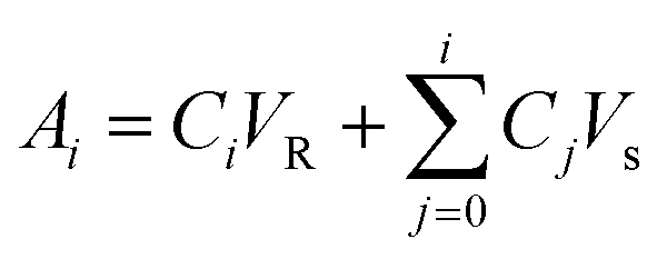
The device modelled in this study was based on previous work validated in rodent models,44,45 but was redesigned to offset the therapy reservoir and actuation reservoirs (Fig. 1A). This was done to facilitate the potential for future delivery of cell cargo. Though this new design has not yet been directly validated in vivo the strain and fluid flow profiles match those used in previously validated designs.49 The device consisted of a central internal therapy reservoir with laser cut semi-permeable membranes on either side. This therapy reservoir was then surrounded by an additional actuation reservoir which could be cyclically inflated and deflated to drive fluid flow (Fig. 1A). The prototyped device was manufactured following previously established techniques44,45 and can be seen in the deflated (top) and inflated (bottom) positions (Fig. 1B). The device was made entirely of thermoplastic polyurethane (TPU). The internal reservoir thickness, or height of the therapy reservoir, was between 0.25 mm and 2 mm and has a cross-sectional diameter of 10 mm. The actuation reservoir surrounding the therapy reservoir was slightly offset and had an additional width of 5 mm.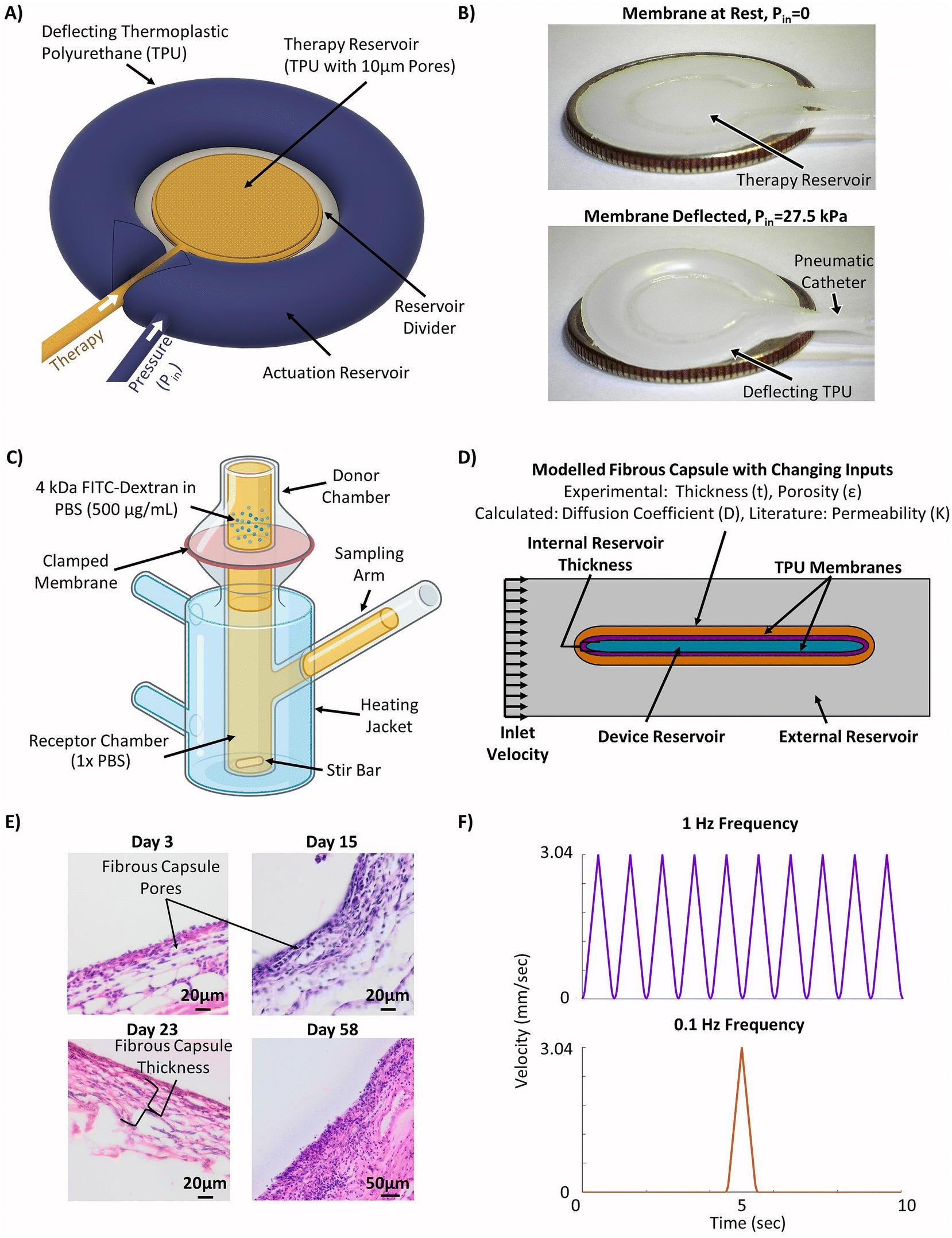 | ||
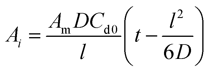
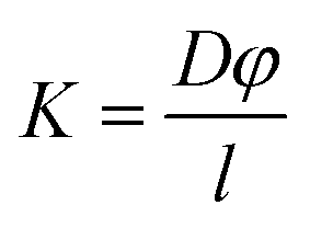
| Fig. 1 Methodology for generating the experimentally informed model. (A) Schematic of the actuatable device (created using Autodesk Fusion 36065). (B) Images of the prototype actuatable device in the deflated (top) and inflated (bottom) states used to drive local fluid flow (American Quarter used for scale, diameter = 24.26 mm). (C) Schematic of Franz cell set-up used for membrane diffusion study (created using Biorender.com). (D) Schematic of the simplified 2D computational model set-up with selected inputs to model the fibrous capsule. (E) Representative H&E stained images of the fibrous capsule developing around a device at days 3, 15, 23, and 58. (F) Velocity profiles used in the models to investigate the efficacy of cyclic flow compared to continuous flow. | ||
Laser cut porous membranes were manufactured at the National Centre for Laser Applications (NCLA) at the University of Galway. The membranes were made from 0.15 mm thick TPU, and the pores were generated using a computer numerical controlled (CNC) laser to melt through the thermoplastic in pre-specified positions. The membranes were then imaged using a scanning electron microscope (SEM). The porosity and pore diameter of the membranes were then analysed using Fiji open-source software.50 The Hough's Circle Transform function was used to measure the diameter of the pores and porosity was determined as the ratio of the total pore area to the total membrane area in the images.
A Franz cell apparatus (PermeGear, cat. no. V3B-02), with a sample solute placed in the donor chamber to diffuse through a permeable membrane over time (Fig. 1C), was used to investigate the diffusional properties of the laser cut TPU membranes in our device. Experiments were carried out using 4 kDa fluorescein isothiocyanate (FITC)-dextran (Sigma Ireland, cat. no. FD4, lot #: BCCG5214, MW: 4064 Da) as an analog of insulin due to their similar molecular weights and approximated hydrodynamic radii (Rh) (Dextran Rh = 1.59 nm, Insulin Rh = 1.34 nm) as calculated using well characterised relations.51 The receptor chamber was loaded with 8 mL of phosphate buffered saline (PBS) solution until it was completely filled and the membranes were carefully placed on top to ensure no bubbles were formed before being clamped in place with a washer. The apparatus was sealed with Parafilm™ to prevent evaporation and the heated jackets were set to 37 °C. The stir bars in the apparatus were turned on and the cells were allowed to reach thermal equilibrium. 0.5 mL of FITC-dextran (500 μg mL−1) in PBS was loaded into the donor chamber of each Franz cell and the timer was started. The Franz cells were resealed with Parafilm™ and covered with aluminium foil to protect them from light. Samples of 375 μL were taken from the centre of the cells after 0.5, 1, 1.5, 2, 3, 5, 7, 9, and 24 hours and fluorescence was measured using a plate reader (HIDEX Sense Microplate Reader, Type 425-311) at excitation/emission wavelengths of 495/520 nm.
The cumulative diffusion release curve was then generated using eqn (1) below:
 | (1) |
The diffusion coefficient was then calculated using a time-lag method based on the slope of the linear portion of the curve and eqn (2) below:52–54
 | (2) |
Finally, the permeability of the membrane (K) was determined using eqn (3) below which assumed a partition coefficient φ of 1.
 | (3) |
2.2 Encapsulation device computational model
A simplified version of the device was modelled in COMSOL Multiphysics®55 (COMSOL, AB, Stockholm, Sweden) using the Transport of Diluted Species and flow through a porous media (Brinkman) modules. The simplified model included a representation of the therapy reservoir and fibrous capsule at various time points to capture the changing transport properties. The actuation reservoir was not directly modelled as its impacts were represented using an idealized flow regimen over the therapy reservoir. A 2D cross section with total width of 10 mm and tapered elliptical ends was used to represent the therapy reservoir (Fig. 1D). The TPU membranes and fibrous capsule were assumed to have uniform thickness surrounding the cell reservoir as additional layers. The initial concentration of insulin in the membranes, fibrous capsule and outer domain were assumed to be zero. The initial therapy reservoir concentration aimed to recapitulate a biologically relevant value. As such, an initial insulin concentration of 9.5 × 10⁻¹³ mol mm−3 was used. This was based on in vitro insulin secretion from a rat β-cell line at high glucose conditions assuming a 10% v/v cell packing density and idealized instantaneous insulin secretion.A step function was applied to the boundary between the reservoir and membranes to resolve the concentration discontinuity. A mesh with maximum element size of 0.1 mm was applied to the internal reservoir and membranes while a coarser mesh with maximum element size of 0.795 mm was used in the outer domain. A boundary layer mesh was then applied over the outside of the membrane and at the top and bottom borders of the outer domain to help resolve the no slip boundary condition. The passive (no flow) version of the model did not incorporate convective local fluid flow around the device.
The fibrous capsule model inputs were generated using previously published data.45,48,56 The capsule thickness and porosity were taken from an 8 weeks study where our devices were implanted in C57BL/6 mice and used to deliver insulin.45 As these parameters change over time as the FBR progresses (Fig. 1E) the capsule was modelled at two key time points, day 15 and day 58 post implantation. The capsule permeability was taken from literature45,56 and the effective diffusion coefficients (Deff) were then approximated for each time point using a version of Maxwell's model,57 a simple and efficient method for estimating the diffusion coefficient in blood and tissue.58–61 In order to ensure a conservative value was obtained using this method, the diffusion coefficient of the solid phase was assumed to be zero eqn (4).62,63
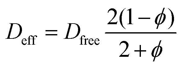 | (4) |
In order to investigate if local fluid flow over the device would aid in insulin transport through the fibrous capsule, a continuous idealized inflow velocity normal to the inlet surface was applied to the left outer domain boundary at two magnitudes: 0.25 mm s−1 and 3.04 mm s−1 (Fig. 1D). These magnitudes were selected based on fluid flow velocities that could be achieved using existing device designs in rodent models.43,45,49 A zero pressure outlet condition was applied to the right outer boundary, and an open diffusion boundary was applied to the outlet to allow for simulated free flow past the device.
As previously introduced a pulsatile flow regimen is explored. The incorporation of two different actuation regimens (to generate local fluid flow) were investigated with frequencies of 1 Hz and 0.1 Hz. Both frequencies utilized the same 1 second long pulse in velocity but this occurred once per second in the 1 Hz frequency (purple) and only once every 10 seconds for the 0.1 Hz frequency (red) (Fig. 1F). These were applied to the model using the same inlet condition as the continuous flow case over a 60 minutes period.
2.3 Model validation
The passive (no flow) version of the model was first validated by ensuring that it provided results approximately equivalent to those obtained by a simplified analytical solution utilizing Fick's law. To this end an equation was derived by combining equations for linear and radial diffusion58 to approximate the transport seen through the device in two dimensions. This assumed a quasi-steady state diffusion and negligible solute amounts contained in the membranes. As such, validation was performed on the model with no simulated FBR to minimize the error in these assumptions. The resulting expression can be seen as eqn (5) below.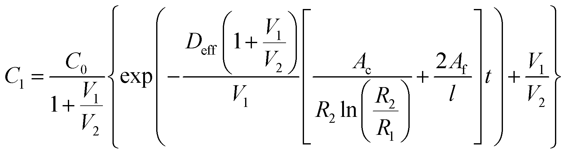 | (5) |
The implementation of the convective element in the model was then similarly validated using an approximation for the device as being two flat plates with freestream velocity V over them. The length averaged mass transfer coefficient  was then calculated using the Sherwood Relation eqn (6) whereby:58
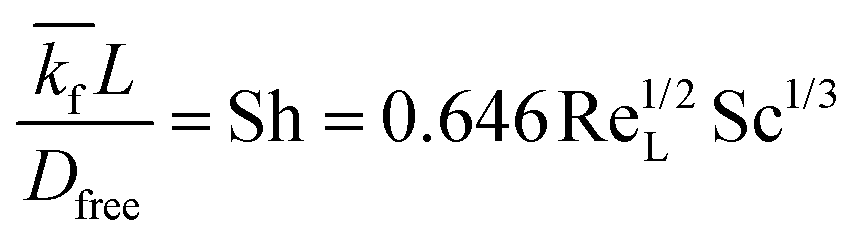 | (6) |
 | (7) |
The resulting mass transfer over time can then be estimated by combining mass transfer relations for the inside of the therapy reservoir  and across the device membrane
  .58 As fluid is continuously entering and being cleared from the domain C2, the concentration outside of the boundary layer, is approximated as zero. The combined equation can then be rearranged and integrated with respect to time in order to obtain eqn (8) below:
 | (8) |
A MATLAB®66 (MATLAB R2021b, The Mathworks Inc., Natick, Massachusetts, USA) script was then generated implementing the equations above in order to compare the approximated analytical solution to the simulated insulin release profiles obtained for the 0.5 mm thick therapy reservoir in both passive and convection-aided release scenarios. Additionally, in order to account for the assumptions inherent in the analytical equations outlined above, the free diffusion coefficient in the fluid domains of the computational model were increased until the solution converged such that a uniform concentration was achieved in the appropriate regions.
2.4 Statistics
All statistical analysis was performed in GraphPad Prism 9.5.1.67 As the data was found to have non-normal distribution using a test of normality, a Mann–Whitney test was performed. All results are presented as mean ± standard deviation (* p < 0.05, ** p < 0.01, *** p < 0.001, **** p < 0.0001).3. Results
3.1 Experimental inputs generated for the model
Images were taken of both surfaces of the laser cut therapy reservoir membranes (Fig. 2A) and showed significantly smaller pore diameters (**** p < 0.0001) on the bottom sides when compared to the top due to the manufacturing technique. This indicated that the bottom sides of 10 μm pore diameter (Fig. 2B) and 3.5% porosity (Fig. 2C) were the rate limiting diffusive factors. The Franz cell set-up was then used to generate a cumulative diffusion curve for the FITC-dextran (Fig. 2D) and found the membrane diffusion and permeability coefficients to be 36.9 ± 4.9 μm2 s−1 and 0.022 ± 0.003 μm2 using eqn (2) and (3) respectively.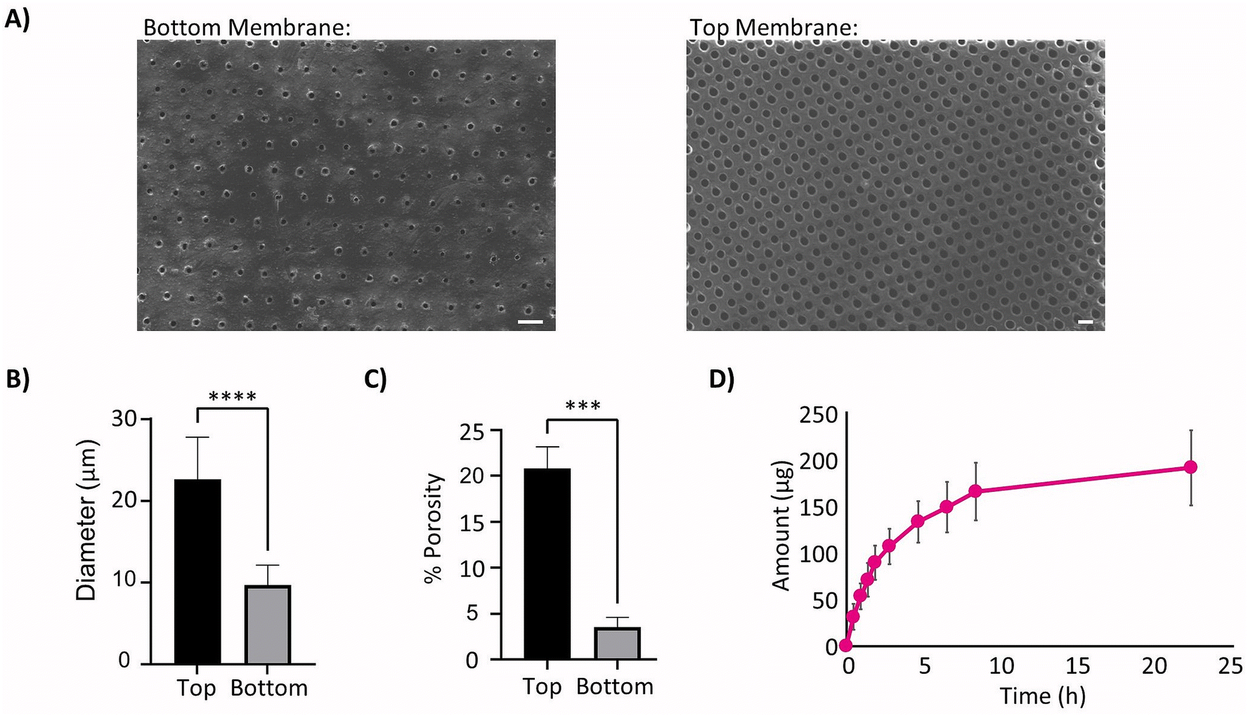 | ||
| Fig. 2 Therapy reservoir membrane parameters. (A) Sample SEM image of the therapy reservoir membrane rate limiting bottom (left) and tops with larger pores (right). Scale Bars 50 μm. (B) Comparison of membrane pore size from bottom and top of membrane, n = 21 images. (C) Comparison of membrane porosity from bottom and top of membrane, n = 8 images. (D) Cumulative diffusion curve of FITC-dextran from Franz cell experimentation. | ||
The experimentally informed inputs were generated for the model mimicking the fibrous capsule, which develops around device after 15 and 58 days respectively, Table 1. Thickness and porosity data were taken from previous studies,45,48 insulin diffusion coefficients were calculated from the porosity data using a simplified Maxwell's model62 and permeability was based on literature.48,56
| Day in vivo | Thickness (μm) | Porosity | Diffusion coefficient (μm2 s−1) | Permeability coefficient (m2) |
|---|---|---|---|---|
| Day 15 | 80 | 0.62 | 78.2 | 5.86 × 10⁻¹⁶ |
| Day 58 | 110 | 0.30 | 33.3 | 4.45 × 10⁻¹⁷ |
3.2 Thinner devices show more efficient therapy release
To confirm that the solutions being obtained from the computational model were valid, the outputs from the model with no simulated fibrous capsule under passive conditions were compared to the approximated analytical solution based on the set-up seen in Fig. 3A which assumes quasi-steady state diffusion across the therapy reservoir membranes as described in the methodology. The results from the computational and analytical solutions over a 60 minutes period were then compared and can be seen to closely follow one another with a maximum difference in insulin release of 0.017 μg (Fig. 3B). | ||
| Fig. 3 Impacts of changing internal therapy reservoir thickness. (A) Diagram depicting set-up for quasi-steady state analytical solution for a device with internal therapy reservoir thickness of 0.5 mm and no flow. (B) Comparison of analytical and computational model outputs. Computational model altered to have uniform concentration inside and outside of the therapy reservoir to mimic analytical assumptions. (C) Model geometry used in simulation, the top image shows the thinnest device investigated (0.25 mm) and the bottom shows the thickest device investigated (2 mm). Internal therapy reservoir volume is shown in red with membranes in purple. (D) Model concentration outputs after 15 minutes for devices of varied internal thickness. (E) Insulin release from the devices over a 60 minutes period. (F) Model area under the curve (AUC) outputs for devices of varied internal thickness at the 15 and 60 minutes time points. | ||
The internal thickness of the therapy reservoir was varied to explore its effect on insulin release. The simplified 2D model of the geometry was generated in COMSOL®55 (Fig. 3C) and insulin release was evaluated over the 60 minutes period following simulated idealized insulin synthesis to mimic postprandial conditions. The thinner devices were shown to be more effective at releasing insulin as demonstrated by the higher proportion of insulin and lower internal therapy concentrations at the most clinically relevant time point of 15 minutes (Fig. 3D). This time point corresponds to the approximate time for the rapid peak in insulin secretion, or first phase insulin secretion, which is seen in vivo and is a major contributor to the control of postprandial hyperglycaemia as well as being linked to later blood glucose levels, especially in individuals with impaired glucose tolerance (IGT).68,69 This increase in insulin release was quantified with the highest value obtained for the thinner device of 0.25 mm (46.1%) after 15 minutes to progressively lower releases of 31.4% (t = 0.5 mm), 18.5% (t = 1.0 mm), 13.1% (t = 1.5 mm), and 10.3% (t = 2.0 mm) as thickness was increased (Fig. 3E). This trend is also seen for the area under the curve (AUC) at both the 15 minutes and 60 minutes time points (Fig. 3F).
3.3 The developing fibrous capsule detrimentally impedes therapy transport
The experimental inputs described above to mimic the developed fibrous capsule at days 15 and 58 post implantation were used to model the resulting FBR over time around a 0.5 mm therapy reservoir (Fig. 4A) and compared with the previous results when there was no fibrous capsule present, mimicking day 0 implantation. Using this altered set-up, the expected decrease in insulin release was captured at days 15 and 58 post implantation, as demonstrated by the lower diffusion distances and concentrations outside the device at the 15 minutes time point (Fig. 4B) and decreased release values over a 60 minutes period (Fig. 4C). The insulin release from the device was quantified over the 60 minutes period and compared with the baseline device value of 66.2% release (no fibrous capsule) showing a reduction to 59.1% and 50.6% at days 15 and 58, respectively. These were correlated with values for the area under the curve (AUC) which were found to be 1.58 × 10⁵, 1.31 × 10⁵, and 1.02 × 10⁵ respectively in terms of percentage released over time (Fig. 4D). These represent relative drops in AUC of 17.2% at day 15 and 35.6% at day 58 relative to baseline after 60 minutes. After 15 minutes, these relative reductions in AUC at days 15 and 58 compared to baseline were found to be 35.8% and 64.2%, respectively, representing a much more severe failure in device performance. | ||
| Fig. 4 Impacts of the fibrous capsule at various time points. (A) Model geometry used to build the device with surrounding fibrous capsule. (B) Concentration in model after 15 minutes with no fibrous capsule, and capsule modelled at days 15 and 58. (C) Insulin release from the device over a 60 minutes period with fibrous capsule (FC) at various times of implantation. (D) Insulin release area under the curve (AUC) at the 15 and 60 minutes time points. | ||
3.4 Therapy release can be restored to baseline by local fluid flow
We hypothesized that the incorporation of local fluid flow over the device could be used to help improve insulin transport and restore functionality that is lost due to the FBR. Therefore, local fluid velocity was incorporated over the therapy reservoir. To confirm that the solutions being obtained from the computational model were reasonable, the outputs from the model were compared to the approximated analytical solution, this time including convective flow based on the set-up shown in Fig. 5A, where the free steam velocity, V, is flowing across two flat plates the length of the therapy reservoir as described in the methodology. The results from the computational and analytical solutions over a 60 minutes period were compared and can be seen to closely follow one another, with a maximum difference in insulin release of 0.013 μg for the free stream velocity of 0.25 mm s−1, and 0.021 μg for the free stream velocity of 3.04 mm s−1 (Fig. 5B).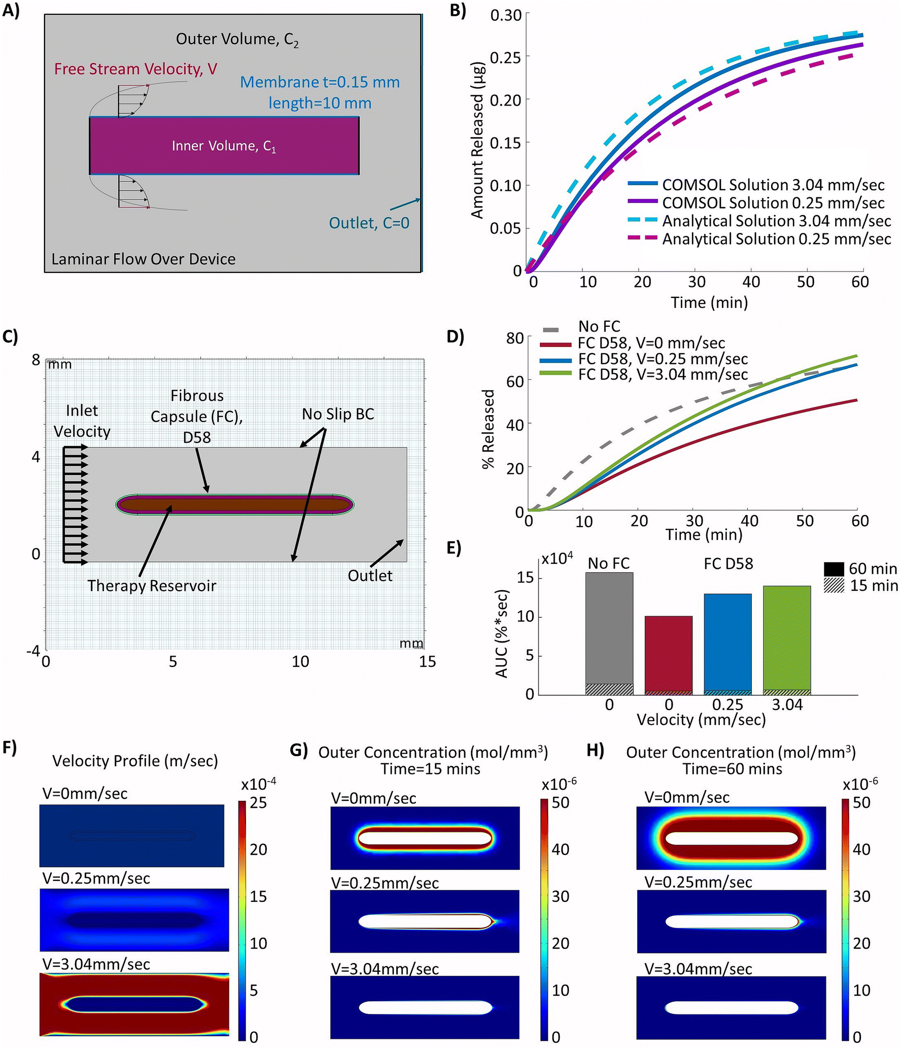 | ||
| Fig. 5 Counteracting the FBR with idealized continuous fluid flow. (A) Diagram depicting set-up for analytical verification based on diffusion through a plate subject to transverse laminar flow. (B) Comparison of analytical and computational model outputs. Computational model altered to have uniform concentration inside of therapy reservoir to mimic analytical assumptions. (C) Model geometry used to build the device with surrounding fibrous capsule (FC) and idealized local fluid flow over the device. (D) Insulin release from the device over a 60 minutes period. (E) Insulin release area under the curve (AUC) at the 15 and 60 minutes time points. (F) Velocity profile for local fluid flow over the device with inlet velocities of 0 mm s−1, 0.25 mm s−1 and 3.04 mm s−1. (G) Concentration profiles of the outside of the device after 15 minutes with inlet velocity set to 0 mm s−1, 0.25 mm s−1 and 3.04 mm s−1. (H) Concentration profiles of the outside of the device after 60 minutes with inlet velocity set to 0 mm s−1, 0.25 mm s−1 and 3.04 mm s−1. | ||
The model geometry was constructed with the simulated fibrous capsule 58 days post implantation and continuous fluid flow velocities that were achievable in previous studies43,45,49 (Fig. 5C). With continuous fluid flow, the insulin release was restored to baseline levels (no fibrous capsule) after 46 and 58 minutes (0.25 mm s−1 and 3.04 mm s−1) respectively (Fig. 5D). However, despite improvements, AUC values were not returned to baseline (Fig. 5E). The flow profiles induced by the selected inlet velocities can be seen in Fig. 5F. Overall, this demonstrated a significant improvement from the case with no local fluid flow. Similarly, minimal accumulation of insulin was seen outside the devices with local fluid flow at both inlet velocities, leading to increased efficiency of release at both the 15 minutes (Fig. 5G) and 60 minutes (Fig. 5H) time points compared to the device with no flow. At the more clinically relevant time point of 15 minutes, baseline values (no fibrous capsule) were not achieved but moderate improvements in release were demonstrated with increasing velocity from 14.8% (V = 0 mm s−1) to 17.5% (V = 0.25 mm s−1) and 19.7% (V = 3.04 mm s−1) respectively. These correlate to relative improvements of 13.5% (V = 0.25 mm s−1) and 29.3% (V = 3.04 mm s−1) AUC over the no flow condition. However, it must be noted that this would still represent a relative decrease in AUC of 59.4% and 53.8% at velocities of 0.25 mm s−1 and 3.04 mm s−1, respectively compared to the baseline (no fibrous capsule) condition at the 15 minutes time point.
3.5 Pulsatile and continuous flow regimens achieve comparable therapy release
The two different proposed cyclic flow regimens were implemented into the local fluid flow model, as shown in Fig. 6A, in order to investigate if different pulsatile flow regimens (purple and red) may be used to achieve similar increases in insulin release to those found with continuous idealized flow (green) over the device. In practice, these may be more readily achievable than continuous flow, as a device can be periodically inflated and deflated to drive interstitial fluid flow (Fig. 6B). The resulting velocity contour profiles achieved at various time points during the device ‘pulse’ as velocity was ramped up and down showed the model was capturing the desired cyclic flow regimens as intended (Fig. 6C). The resulting release profiles over a 60 minutes period showed that actuation at a frequency of 1 Hz was sufficient to nearly match that of the device with continuous flow (Fig. 6D), demonstrating a relative difference in AUC of only 1.8% and highlighting that pulsatile flow could be used as a viable alternative to continuous flow. Additionally, although the 0.1 Hz pulsatile flow was not able to match that of continuous flow over the device, there remained only a modest relative difference in AUC of 9.2% (Fig. 6E).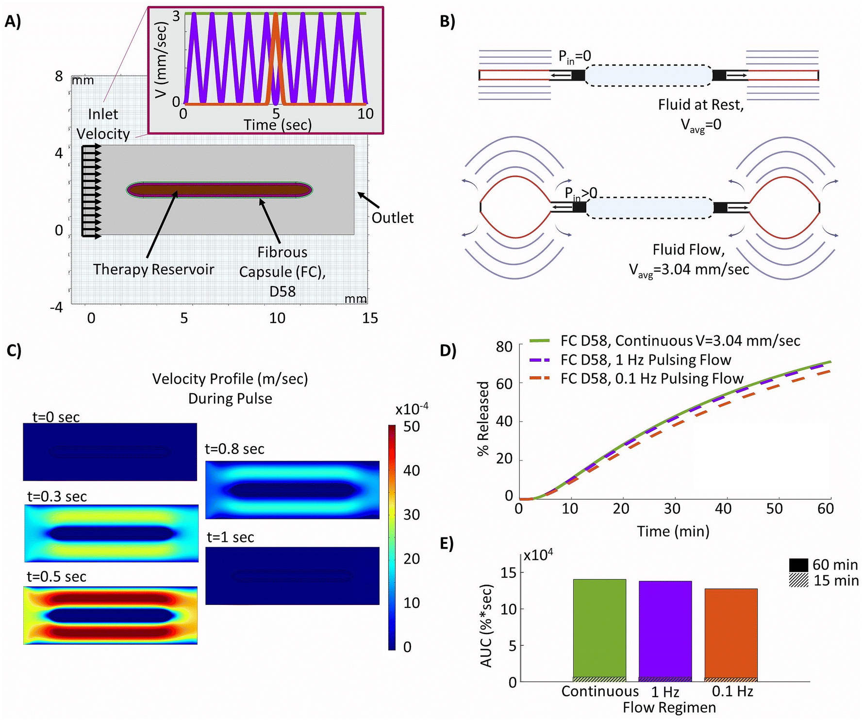 | ||
| Fig. 6 Optimizing a pulsatile fluid flow regimen. (A) Model geometry used to build the device with surrounding day 58 fibrous capsule (FC) and pulsatile fluid flow over the device – continuous flow (green), 1 Hz pulse (purple), 0.1 Hz pulse (red). (B) Diagrams of an actuatable device in deflated and inflated deflection positions to drive flow49 (created using Biorender.com). (C) Velocity profile for of fluid flow over the device at various time points within each pulse, t = 0 at start of ramp to velocity profile. (D) Insulin release from the device over a 60 minutes period. (E) Insulin release area under the curve (AUC) at the 15 and 60 minutes time points. | ||
4. Discussion
We describe a simplified encapsulation device model informed by experimental inputs which can be used to investigate how therapy release is impacted by device geometry, the fibrous capsule resulting from the FBR, and the implementation of local continuous and pulsatile fluid flow around the device. This enables greater insight into how we expect the device to perform in vivo under a variety of conditions and to tune our design accordingly.The model captures an increase in therapy release with decreasing device thickness, likely resulting from the increasing surface to volume ratio and decreased diffusion lengths. However, it must be noted that in practice, sufficiently thin devices, on the order of 0.25 mm, may be difficult to manufacture. It was also noted that if the device length and therapy concentration are maintained consistent, as would likely be the case in practice for cell encapsulation devices, the reservoir volume will also decrease with thickness. Therefore, the device dimensions would need to be optimized on the basis of this trade-off. These dimensions will also be limited by the availability of space for implants in potential surgically attractive sites such as the peritoneal, subcutaneous, or posterior rectus sheath.70 Conversely, increasing device thickness will also increase the diffusion distance, and hence lag-time for the transport of factors such as oxygen, nutrients, and glucose which are critical to encapsulated cell viability, especially in the case of insulin producing β-cells which are sensitive to even moderate decreases in oxygen tension.71 For these reasons, an ideal device thickness of 0.5 mm was selected and used for further variable investigations in this paper. This selection also aligns with the optimized device parameters suggested by Ernst et al.72 based on detailed analysis of oxygen transport and islet performance in encapsulation devices notwithstanding the FBR.
Our model assumes an immediate increase in therapy reservoir concentration, which would not be the case with cell encapsulation devices, specifically in the case of T1D as explored here. As such, it does not fully reflect the expected release profiles due to the delays for glucose to diffuse into the device and the islets to react accordingly by synthesizing and releasing insulin. However, these impacts are somewhat mitigated by the much smaller molecular weight of glucose (approximately 0.18 kDa compared to 5.8 kDa) and the rapid initial peak in insulin production from stimulated cells. Furthermore, although the delay in insulin release from the islets could be captured through the addition of a reaction within the device model for the rate dependence, this work focused on therapy transport through realistic device membrane materials and overcoming the FBR through fluid flow. Additionally, other potential cells for encapsulation in the device, such as stem cells for cardiovascular therapy, may not be reliant on these delayed sensing and synthesis times. Therefore, our model can be used as a platform to better understand how varied factors impact therapy release and what may be used to improve it. This was also why the percentage released was used as a comparative measure of device performance rather than an amount of insulin.
Perhaps more critical to device functionality is the FBR which leads to the development of a dense, hypo-permeable fibrous capsule around the therapy reservoir upon implantation in vivo. Our model is able to capture the expected decrease in therapy release that would result from the FBR at two critical time points, days 15 and 58, using experimentally informed inputs. For this purpose, the FBR was simulated by incorporating the relevant transport properties of the developed fibrous capsule, the major barrier to therapy release, with insulin as the sample agent. However, it should be noted that other factors, such as glucose uptake by the fibrous capsule tissue73 and decreased oxygen permeability,19,72 may impact these results further in the case of islet encapsulation devices. In the more general case of cell encapsulation devices, this may still be of concern due to factor and nutrient uptake in the fibrous capsule, and cell hypoxia with decreased oxygenation. Despite this potential limitation, the results obtained from this study remain within reasonable expectations and are highly applicable as a model that is focused on comparative therapy release. As further evidence of this, the expected deficits in insulin release from our model at days 15 and 58 (35.8% and 64.2% relative drop in AUC compared to baseline after 15 minutes, Fig. 4D) correlate reasonably well with the percentage reduction in the maximum percentage blood glucose drop at 3 and 8 weeks seen in vivo (43% and 71%, respectively relative to baseline).45 Though these values cannot be directly equated, they show a similar trend and magnitude of change, as expected given the intrinsic links between insulin release and blood glucose. This is especially promising as direct experimental validation of the model was not carried out as the required complex ex vivo set-up would be prone to error. The ability to obtain the fibrous capsule transport properties used in the model of insulin transport from a combination of histological data and conservative calculated estimates, thereby eliminating the need for this complex customizable set-up, is highly advantageous. However, this method of approximating the capsule diffusion properties may not apply to all therapies and would require additional validation to ensure reliable estimates are achieved. As the FBR is a leading cause of implantable device failure,36–40 being able to quantify and predict its impacts and how this may change over time is highly relevant and important to future device design for the delivery of drug or cell therapy.
Our model is able to capture how the implementation of local fluid flow around the device may be used to help improve therapy transport and overcome the diffusional barrier caused by the FBR. Several groups have begun investigating how the incorporation of fluid flow around an implant may be used to help improve cell health and nutrient exchange within encapsulation devices.43,45,46 Specifically, our previous studies with similar devices have demonstrated the ability to reduce the magnitude of the FBR and improve therapy release through the device in both mouse and rat models.44,45 However, this has not yet been directly validated in vivo for the new device proposed herein. This new design builds on our previous work, but for the first time the actuation and therapy reservoirs are offset. This allows simultaneous therapy encapsulation and actuation, while maintaining the same induced strain profiles and fluid flow velocities as in the previously validated designs.49 Our model therefore implements idealized fluid flow velocities within the magnitudes achieved by these existing designs and is able to show an improvement in insulin release at the clinically relevant time point of 15 minutes, and a return to release equivalent to the baseline case (no fibrous capsule) within 60 minutes (Fig. 5D). This is promising as an early peak corresponding to first-phase insulin secretion followed by a more steady release is a hallmark of proper glycaemic control, though the lower 15 minutes release compared to baseline may require further investigation due to its strong links with diabetes onset74 and postprandial hyperglycaemia in individuals with IGT.68,69 Additionally, although not explored in this model, our previous studies have shown that the incorporation of actuation (causing local fluid flow and tissue strain) around implantable devices decreases the magnitude of the FBR and resulting fibrous capsule as detailed above.44,45,49 As such, the incorporation of a local flow regimen may induce a dual improvement in therapy release through the combined reduction in FBR and advantageous convective transport elements, thereby mitigating the delayed insulin release and impaired 15 minutes response seen in the model.
Although this model was generated using insulin as a representative therapy, these findings would also be highly applicable to the delivery of other drugs or cell therapies which rely on timely and accurate transport which can be inhibited by the FBR.34,75 Though many therapies and cell products used in such devices would vary in molecular weights, meaning their transport properties would not be comparable to those of insulin as described above, the methodology outlined in this model may serve as a baseline for their evaluation. Among these potential examples would be anti-fibrotic compounds such as dexamethasone (0.3 kDa), or stem cells which have been engineered to overexpress key factors for wound healing such as vascular endothelial growth factor (VEGF, 21 kDa) and transforming growth factor β (25 kDa). Additionally, this approach to overcoming the impacts of the FBR may have implications for future investigations into other implants such as biosensors and nerve neuroprosthetics which are detrimentally impacted by the development of the fibrous capsule.38,76
Furthermore, when evaluating the device's potential for cell encapsulation and subsequent clinical translation, an important consideration is the membrane characteristics. The membrane pore size evaluated herein was selected based on the trade-offs between ease of manufacturing, effective factor transport, and immune protection, in addition to aligning with our previous studies as a proof of concept in both drug delivery and cell encapsulation. Although the current pore size would serve as an immune barrier to most inflammatory cell infiltration (∼10 μm),21 it would not protect against them completely, nor against infiltration of smaller immune factors. Therefore, these membranes would not be suitable for allogenic cell encapsulation without immunosuppression. However, smaller pore sizes could be achieved and implemented in future. An optimal immunoprotective pore size on the magnitude of 10–100 nm has been suggested,77 but due to the similar molecular size of proinflammatory factors such as cytokine interleukin-1β (Rh: 2.18 nm) or antibody immunoglobulin G (Rh: 5.9 nm), and vital factors such as insulin (Rh: 1.34 nm), there is a very tight range for control in a fully immunoprotective device.21,77 Current devices, especially in the field of T1D, have therefore struggled with the balance between effective factor transport and immune protection with well-known devices such as Theracyte™ using a pore size of 400 nm.78,79 However, if rapid and effective factor transport through membranes with smaller more suitable pores could be achieved, potentially through the incorporation of local fluid flow, this may serve as a solution. The membrane thickness and cell packing density also play a factor in device performance when used to encapsulate cells. In general, thinner device membranes are preferable to reduce the diffusion distance. Recommended device thickness and cell packing density (0.4–0.6 mm, 5–10% v/v)19 for T1D are based on passive diffusion alone and may differ depending upon flow velocity, cell type, and factors such as the oxygen consumption rates. As the membrane transport properties will change with pore size and membrane thickness these could then be re-evaluated to provide updated inputs to the model to remain device specific in the future.
Finally, we demonstrate that pulsatile flow regimens are able to achieve comparable improvements to those seen in continuous flow cases, with relative differences in the AUC of only 1.8% (1 Hz regimen) and 9.2% (0.1 Hz regimen) compared to continuous flow. This would facilitate the incorporation of induced interstitial fluid flow into practical device designs. Incorporating these varied flow profiles over time may hold the key to overcoming the critical diffusion barrier, which currently leads to consistent device failure in vivo, and this model may be used as a method to test and optimize simulated flow regimens readily achievable by existing designs that are suitable for a clinical setting. Overall, the computational model outlined herein may serve as a valuable means to investigate the impacts of the FBR and how they may be overcome.
5. Conclusion
In conclusion, the experimentally informed models outlined in this paper may serve as an important design tool to help quantify the impacts of implantable encapsulation device design and the FBR on therapy release post implantation, as well as how the FBR may be overcome using local fluid flow. As implantable encapsulation device failure is often a consequence of poor factor transport which is further inhibited by the FBR, the ability to model its progressive impediment to therapy release and demonstrate a recovery in device performance with a pulsatile flow regimen provides powerful insights into future optimization. Understanding the degree to which transport is impacted and how fluid flow may be implemented to overcome it will be crucial towards future progress in the development of implantable technologies.Author contributions
LT, NAW, GPD and EBD designed the study. LT, NAW, and RB conducted the experiments. LT, NAW and RT conducted the formal analysis. LT, NAW, RT, EW, JOD, WR, GPD and EBD conceptualized the experiments. LT, NAW, RT, EW, JOD, WR, GPD and EBD validated methods and/or results. LT and EBD wrote the manuscript. All authors reviewed and edited the manuscript.Conflicts of interest
There are no conflicts of interest to declare.Acknowledgements
L. T. acknowledges funding from the Irish Research Council (GOIPG/2022/984). R. T. acknowledges funding from SFI's research centre for medical devices (SFI/13/RC/2073_P2 and SFI's C2C-GCMP: 19/US-C2C/3633). N. A. W. and E. B. D. acknowledge funding from the Science Foundation Ireland Royal Society University Research Fellowship (URF\R1\191335). E. B. D. acknowledges funding from the Irish Research Council Starting Laureate Award (IRCLA/2022/2766). G. P. D. acknowledges funding from CÚRAM, SFI Centre for medical devices (SFI/13/RC/2073_P2) and funding from AMBER, SFI Centre for materials research (SFI/12/RC/2278_P2).The authors acknowledge the Centre for Microscopy and Imaging at the University of Galway (CMI). We also thank Mr Mark Canney for technical support. Fig. 1C, and Fig. 6B were created with Biorender.com.
References
- F. P. Pons-Faudoa, A. Ballerini, J. Sakamoto and A. Grattoni, Advanced implantable drug delivery technologies: transforming the clinical landscape of therapeutics for chronic diseases, Biomed. Microdevices, 2019, 21(2), 47 CrossRef PubMed.
- E. Magill, S. Demartis, E. Gavini, A. D. Permana, R. R. S. Thakur and M. F. Adrianto, et al., Solid implantable devices for sustained drug delivery, Adv. Drug Delivery Rev., 2023, 199, 114950 CrossRef CAS PubMed.
- C. J. Kearney and D. J. Mooney, Macroscale delivery systems for molecular and cellular payloads, Nat. Mater., 2013, 12(11), 1004–1017 CrossRef CAS PubMed.
- W. Zakrzewski, M. Dobrzyński, M. Szymonowicz and Z. Rybak, Stem cells: past, present, and future, Stem Cell Res. Ther., 2019, 10(1), 68 CrossRef CAS PubMed.
- Towards advanced cell therapies, Nat. Biomed. Eng., 2018, 2(6), 339–340 CrossRef PubMed.
- J. Chu, F. Gao, M. Yan, S. Zhao, Z. Yan and B. Shi, et al., Natural killer cells: a promising immunotherapy for cancer, J. Transl. Med., 2022, 20(1), 240 CrossRef CAS PubMed.
- N. Shimasaki, A. Jain and D. Campana, NK cells for cancer immunotherapy, Nat. Rev. Drug Discovery, 2020, 19(3), 200–218 CrossRef CAS PubMed.
- S. Liu, V. Galat, Y. Galat4, Y. K. A. Lee, D. Wainwright and J. Wu, NK cell-based cancer immunotherapy: from basic biology to clinical development, J. Hematol. Oncol., 2021, 14(1), 7 CrossRef CAS PubMed.
- S. L. Maude, T. W. Laetsch, J. Buechner, S. Rives, M. Boyer and H. Bittencourt, et al., Tisagenlecleucel in Children and Young Adults with B-Cell Lymphoblastic Leukemia, N. Engl. J. Med., 2018, 378(5), 439–448 CrossRef CAS PubMed.
- S. J. Schuster, M. R. Bishop, C. S. Tam, E. K. Waller, P. Borchmann and J. P. McGuirk, et al., Tisagenlecleucel in Adult Relapsed or Refractory Diffuse Large B-Cell Lymphoma, N. Engl. J. Med., 2019, 380(1), 45–56 CrossRef CAS PubMed.
- N. Raje, J. Berdeja, Y. Lin, D. Siegel, S. Jagannath and D. Madduri, et al., Anti-BCMA CAR T-Cell Therapy bb2121 in Relapsed or Refractory Multiple Myeloma, N. Engl. J. Med., 2019, 380(18), 1726–1737 CrossRef CAS PubMed.
- J. A. Myers and J. S. Miller, Exploring the NK cell platform for cancer immunotherapy, Nat. Rev. Clin Oncol., 2021, 18(2), 85–100 CrossRef PubMed.
- R. Handgretinger, L. Peter and A. Mc, Exploitation of natural killer cells for the treatment of acute leukemia, Blood, 2016, 127(26), 3341–3349 CrossRef CAS PubMed.
- J. S. Miller, Y. Soignier, A. Panoskaltsis-Mortari, S. A. McNearney, G. H. Yun and S. K. Fautsch, et al., Successful adoptive transfer and in vivo expansion of human haploidentical NK cells in patients with cancer, Blood, 2005, 105(8), 3051–3057 CrossRef CAS PubMed.
- G. P. Duffy, S. T. Robinson, R. O'Connor, R. Wylie, C. Mauerhofer and G. Bellavia, et al., Implantable Therapeutic Reservoir Systems for Diverse Clinical Applications in Large Animal Models, Adv. Healthc. Mater., 2020, 9(11), 2000305 CrossRef CAS PubMed.
- M. A. Laflamme, S. Zbinden, S. E. Epstein and C. E. Murry, Cell-Based Therapy for Myocardial Ischemia and Infarction: Pathophysiological Mechanisms, Annu. Rev. Pathol.: Mech. Dis., 2007, 2(1), 307–339 CrossRef CAS PubMed.
- J. J. Gavira, E. Nasarre, G. Abizanda, M. Pérez-Ilzarbe, A. de Martino-Rodriguez and J. A. García de Jalón, et al., Repeated implantation of skeletal myoblast in a swine model of chronic myocardial infarction, Eur. Heart J., 2010, 31(8), 1013–1021 CrossRef PubMed.
- S. H. Li, T. Y. Y. Lai, Z. Sun, M. Han, E. Moriyama and B. Wilson, et al., Tracking cardiac engraftment and distribution of implanted bone marrow cells: Comparing intra-aortic, intravenous, and intramyocardial delivery, J. Thorac. Cardiovasc. Surg., 2009, 137(5), 1225–1233 CrossRef PubMed.
- D. Goswami, D. A. Domingo-Lopez, N. A. Ward, J. R. Millman, G. P. Duffy and E. B. Dolan, et al., Design Considerations for Macroencapsulation Devices for Stem Cell Derived Islets for the Treatment of Type 1 Diabetes, Adv. Sci., 2021, 8(16), e2100820 CrossRef PubMed.
- W. Whyte, E. T. Roche, C. E. Varela, K. Mendez, S. Islam and H. O'Neill, et al., Sustained release of targeted cardiac therapy with a replenishable implanted epicardial reservoir, Nat. Biomed. Eng., 2018, 2(6), 416–428 CrossRef CAS PubMed.
- J. Schweicher, C. Nyitray and T. A. Desai, Membranes to achieve immunoprotection of transplanted islets, Front. Biosci., Landmark Ed., 2014, 19, 49–76 CrossRef PubMed.
- N. J. Hogrebe, M. Ishahak and J. R. Millman, Developments in stem cell-derived islet replacement therapy for treating type 1 diabetes, Cell Stem Cell, 2023, 30(5), 530–548 CrossRef CAS PubMed.
- T. W. Reichman, C. Ricordi, A. Naji, J. F. Markmann, B. A. Perkins and M. Wijkstrom, et al., 836-P: Glucose-Dependent Insulin Production and Insulin-Independence in Type 1 Diabetes from Stem Cell–Derived, Fully Differentiated Islet Cells—Updated Data from the VX-880 Clinical Trial, Diabetes, 2023, 72(Supplement_1), 836-P CrossRef.
- M. F. Nijhoff and E. J. P. de Koning, Artificial Pancreas or Novel Beta-Cell Replacement Therapies: a Race for Optimal Glycemic Control?, Curr. Diabetes Rep., 2018, 18(11), 110 CrossRef PubMed.
- A. Singh, N. Afshan, A. Singh, S. K. Singh, S. Yadav and M. Kumar, et al., Recent trends and advances in type 1 diabetes therapeutics: A comprehensive review, Eur. J. Cell Biol., 2023, 102(2), 151329 CrossRef CAS PubMed.
- W. Liu, J. A. Flanders, L. H. Wang, Q. Liu, D. T. Bowers and K. Wang, et al., A Safe, Fibrosis-Mitigating, and Scalable Encapsulation Device Supports Long-Term Function of Insulin-Producing Cells, Small, 2022, 18(8), e2104899 CrossRef PubMed.
- D. An, A. Chiu, J. A. Flanders, W. Song, D. Shou and Y. C. Lu, et al., Designing a retrievable and scalable cell encapsulation device for potential treatment of type 1 diabetes, Proc. Natl. Acad. Sci. U. S. A., 2018, 115(2), E263E–E2272 CrossRef PubMed.
- A. J. Vegas, O. Veiseh, M. Gürtler, J. R. Millman, F. W. Pagliuca and A. R. Bader, et al., Long-term glycemic control using polymer-encapsulated human stem cell-derived beta cells in immune-competent mice, Nat. Med., 2016, 22(3), 306–311 CrossRef CAS PubMed.
- L. H. Wang, A. U. Ernst, J. A. Flanders, W. Liu, X. Wang and A. K. Datta, et al., An inverse-breathing encapsulation system for cell delivery, Sci. Adv., 2021, 7(20), eabd5835 CrossRef CAS PubMed , Available from: https://www.science.org.
- S. Bose, L. R. Volpatti, D. Thiono, V. Yesilyurt, C. McGladrigan and Y. Tang, et al., A retrievable implant for the long-term encapsulation and survival of therapeutic xenogeneic cells, Nat. Biomed. Eng., 2020, 4(8), 814 CrossRef CAS PubMed.
- J. Magisson, A. Sassi, A. Kobalyan, C. T. Burcez, R. Bouaoun and M. Vix, et al., A fully implantable device for diffuse insulin delivery at extraperitoneal site for physiological treatment of type 1 diabetes, J. Controlled Release, 2020, 320, 431–441 CrossRef CAS PubMed.
- U. Bhardwaj, R. Sura, F. Papadimitrakopoulos and D. J. Burgess, PLGA/PVA hydrogel composites for long-term inflammation control following s.c. implantation, Int. J. Pharm., 2010, 384(1), 78–86 CrossRef CAS PubMed.
- D. Zhang, Q. Chen, C. Shi, M. Chen, K. Ma and J. Wan, et al., Dealing with the Foreign-Body Response to Implanted Biomaterials: Strategies and Applications of New Materials, Adv. Funct. Mater., 2021, 31(6), 2007226 CrossRef CAS.
- O. Veiseh and A. J. Vegas, Domesticating the foreign body response: Recent advances and applications, Adv. Drug Delivery Rev., 2019, 144, 148–161 CrossRef CAS PubMed.
- F. B. Coulter, R. E. Levey, S. T. Robinson, E. B. Dolan, S. Deotti and M. Monaghan, et al., Additive Manufacturing of Multi-Scale Porous Soft Tissue Implants That Encourage Vascularization and Tissue Ingrowth, Adv. Healthc. Mater., 2021, 10(14), 2100229 CrossRef CAS PubMed.
- M. T. Novak and W. M. Reichert, Modeling the physiological factors affecting glucose sensor function in Vivo, J. Diabetes Sci. Technol., 2015, 9(5), 993–998 CrossRef CAS PubMed.
- P. M. McClatchey, E. S. McClain, I. M. Williams, C. M. Malabanan, F. D. James and P. C. Lord, et al., Fibrotic Encapsulation Is the Dominant Source of Continuous Glucose Monitor Delays, Diabetes, 2019, 68(10), 1892–1901 CrossRef CAS PubMed.
- A. Carnicer-Lombarte, S. T. Chen, G. G. Malliaras and D. G. Barone, Foreign Body Reaction to Implanted Biomaterials and Its Impact in Nerve Neuroprosthetics, Front. Bioeng. Biotechnol., 2021, 9, 271 Search PubMed.
- R. Beatty, C. E. Lu, J. Marzi, R. E. Levey, D. C. Berrio and G. Lattanzi, et al., The Foreign Body Response to an Implantable Therapeutic Reservoir in a Diabetic Rodent Model, Tissue Eng., Part C, 2021, 27(10), 515–528 CrossRef CAS PubMed.
- B. N. Kharbikar, G. S. Chendke and T. A. Desai, Modulating the Foreign Body Response of Implants for Diabetes Treatment, Adv. Drug Delivery Rev., 2021, 174, 87 CrossRef CAS PubMed.
- S. R. Bornstein, B. Ludwig and C. Steenblock, Progress in islet transplantation is more important than ever, Nat. Rev. Endocrinol., 2022, 18(7), 389–390 CrossRef PubMed.
- O. Alcazar and P. Buchwald, Concentration-Dependency and Time Profile of Insulin Secretion: Dynamic Perifusion Studies With Human and Murine Islets, Front. Endocrinol., 2019, 10, 680 CrossRef PubMed.
- K. Yang, E. D. O’Cearbhaill, S. S. Liu, A. Zhou, G. D. Chitnis and A. E. Hamilos, et al., A therapeutic convection-enhanced macroencapsulation device for enhancing β cell viability and insulin secretion, Proc. Natl. Acad. Sci. U. S. A., 2021, 118(37), e2101258118 CrossRef CAS PubMed.
- E. B. Dolan, C. E. Varela, K. Mendez, W. Whyte, R. E. Levey and S. T. Robinson, et al., An actuatable soft reservoir modulates host foreign body response, Sci. Robot., 2019, 4(33), eaax7043 CrossRef PubMed.
- W. Whyte, D. Goswami, S. X. Wang, Y. Fan, N. A. Ward and R. E. Levey, et al., Dynamic actuation enhances transport and extends therapeutic lifespan in an implantable drug delivery platform, Nat. Commun., 2022, 13, 4496 CrossRef CAS PubMed.
- S. A. Fernandez, L. Danielczak, G. Gauvin-Rossignol, C. Hasilo, A. Bégin-Drolet and J. Ruel, et al., An in vitro Perfused Macroencapsulation Device to Study Hemocompatibility and Survival of Islet-Like Cell Clusters, Front. Bioeng. Biotechnol., 2021, 9, 429 Search PubMed.
- S. A. Fernandez, K. S. Champion, L. Danielczak, M. Gasparrini, S. Paraskevas and R. L. Leask, et al., Engineering Vascularized Islet Macroencapsulation Devices: An in vitro Platform to Study Oxygen Transport in Perfused Immobilized Pancreatic Beta Cell Cultures, Front. Bioeng. Biotechnol., 2022, 10, 884071 CrossRef PubMed.
- R. Beatty, K. L. Mendez, L. H. J. Schreiber, R. Tarpey, W. Whyte and Y. Fan, et al., Soft robot–mediated autonomous adaptation to fibrotic capsule formation for improved drug delivery, Sci. Robot., 2023, 8(81), eabq4821 CrossRef PubMed.
- N. A. Ward, S. Hanley, R. Tarpey, L. H. J. Schreiber, J. O’Dwyer and E. T. Roche, et al., Intermittent actuation attenuates fibrotic behaviour of myofibroblasts, Acta Biomater., 2023, 80–92 Search PubMed.
- J. Schindelin, I. Arganda-Carreras, E. Frise, V. Kaynig, M. Longair and T. Pietzsch, et al., Fiji: an open-source platform for biological-image analysis, Nat. Methods, 2012, 9(7), 676–682 CrossRef CAS PubMed.
- M. Briššová, M. Petro, I. Lacík, A. C. Powers and T. Wang, Evaluation of Microcapsule Permeability via Inverse Size Exclusion Chromatography, Anal. Biochem., 1996, 242(1), 104–111 CrossRef PubMed.
- J. Crank, The Mathematics of Diffusion, Clarendon press, Oxford, 1975 Search PubMed.
- W. Zhang and S. Furusaki, On the evaluation of diffusivities in gels using the diffusion cell technique, Biochem. Eng. J., 2001, 9(1), 73–82 CrossRef CAS.
- R. N. Shirazi, S. Islam, F. M. Weafer, W. Whyte, C. E. Varela and A. Villanyi, et al., Multiscale Experimental and Computational Modeling Approaches to Characterize Therapy Delivery to the Heart from an Implantable Epicardial Biomaterial Reservoir, Adv. Healthc. Mater., 2019, 8(16), 1900228 CrossRef PubMed.
- . COMSOL Multiphysics®, COMSOL, AB, Stockholm, Sweden. Available from: https://www.comsol.com.
- B. S. Gardiner, D. W. Smith, M. Coote and J. G. Crowston, Computational Modeling of Fluid Flow and Intra-Ocular Pressure following Glaucoma Surgery, PLoS One, 2010, 5(10), e13178 CrossRef PubMed.
- J. C. Maxwell, A treatise on electricity and magnetism, Clarendon Press, Oxford, vol. 1, p. 1873 Search PubMed.
- R. L. Fournier, Basic Transport Phenomena in Biomedical Engineering, CRC Press, 3rd edn, 2011 Search PubMed.
- Y. Demirel and V. Gerbaud, Chapter 11 - Thermodynamics and Biological Systems, in Nonequilibrium Thermodynamics, ed. Y. Demirel and V. Gerbaud, Elsevier, 4th edn, 2019, pp. 489–571. Available from: https://www.sciencedirect.com/science/article/pii/B9780444641120000113 Search PubMed.
- E. Syková and C. Nicholson, Diffusion in Brain Extracellular Space, Physiol. Rev., 2008, 88(4), 1277–1340 CrossRef PubMed.
- R. Chebbi, An analytical model for solute transport from blood to tissue, Open Phys., 2022, 20(1), 249–258 CrossRef CAS.
- A. A. Sharkawy, B. Klitzman, G. A. Truskey and W. M. Reichert, Engineering the tissue which encapsulates subcutaneous implants. I. Diffusion properties, J. Biomed. Mater. Res., 1997, 37, 401–412 CrossRef CAS PubMed.
- A. W. el-Kareh, S. L. Braunstein and T. W. Secomb, Effect of cell arrangement and interstitial volume fraction on the diffusivity of monoclonal antibodies in tissue, Biophys. J., 1993, 64(5), 1638–1646 CrossRef CAS PubMed.
- P. Buchwald, A local glucose-and oxygen concentration-based insulin secretion model for pancreatic islets, Theor. Biol. Med. Modell., 2011, 8, 20 CrossRef CAS PubMed.
- . Fusion 360, Autodesk, [cited 2024 Mar 20]. Available from: https://www.autodesk.com/products/fusion-360.
- . MATLAB®, The MathWorks Inc., 2021. Available from: https://www.mathworks.com.
- . GraphPad Prism, GraphPad, Boston, Massachusetts USA.
- S. Del Prato, Loss of early insulin secretion leads to postprandial hyperglycaemia, Diabetologia, 2003, 46(1), M2–M8 CrossRef CAS PubMed.
- G. Di Giuseppe, G. Ciccarelli, L. Soldovieri, U. Capece, C. M. A. Cefalo and S. Moffa, et al., First-phase insulin secretion: can its evaluation direct therapeutic approaches?, Trends Endocrinol. Metab., 2023, 34(4), 216–230 CrossRef CAS PubMed.
- B. McDermott, S. Robinson, S. Holcombe, R. E. Levey, P. Dockery and P. Johnson, et al., Developing a morphomics framework to optimize implant site-specific design parameters for islet macroencapsulation devices, J. R. Soc., Interface, 2021, 18(185), 20210673 CrossRef CAS PubMed.
- P. Buchwald, A. Tamayo-Garcia, V. Manzoli, A. A. Tomei and C. L. Stabler, Glucose-Stimulated Insulin Release: Parallel Perifusion Studies of Free and Hydrogel Encapsulated Human Pancreatic Islets, Biotechnol. Bioeng., 2018, 115(1), 232 CrossRef CAS PubMed.
- A. U. Ernst, L. H. Wang, S. C. Worland, B. A. Marfil-Garza, X. Wang and W. Liu, et al., A predictive computational platform for optimizing the design of bioartificial pancreas devices, Nat. Commun., 2022, 13(1), 1–18 CrossRef.
- O. Didyuk, N. Econom, A. Guardia, K. Livingston and U. Klueh, Continuous Glucose Monitoring Devices: Past, Present, and Future Focus on the History and Evolution of Technological Innovation, J. Diabetes Sci. Technol., 2020, 15(3), 676–683 CrossRef PubMed.
- G. C. Weir and S. Bonner-Weir, Reduced glucose-induced first-phase insulin release is a danger signal that predicts diabetes, J. Clin. Invest., 2021, 131(12), e150022 CrossRef CAS PubMed.
- B. D. Ratner, Reducing capsular thickness and enhancing angiogenesis around implant drug release systems, J. Controlled Release, 2002, 78(1), 211–218 CrossRef CAS PubMed.
- Y. Onuki and F. Papadimitrakopoulos, A Review of the Biocompatibility of Implantable Devices: Current Challenges to Overcome Foreign Body Response, J. Diabetes Sci. Technol., 2008, 2(6), 922–1163 CrossRef PubMed.
- R. Chang, G. Faleo, H. A. Russ, A. V. Parent, S. K. Elledge and D. A. Bernards, et al., Nanoporous Immunoprotective Device for Stem-Cell-Derived β-Cell Replacement Therapy, ACS Nano, 2017, 11(8), 7747–7757 CrossRef CAS PubMed.
- M. Kumagai-Braesch, S. Jacobson, H. Mori, X. Jia, T. Takahashi and A. Wernerson, et al., The TheraCyteTM Device Protects against Islet Allograft Rejection in Immunized Hosts, Cell Transplant., 2013, 22(7), 1137–1146 Search PubMed.
- U. Barkai, A. Rotem and P. de Vos, Survival of encapsulated islets: More than a membrane story, World J. Transplant, 2016, 6(1), 69–90 CrossRef PubMed.
| This journal is © The Royal Society of Chemistry 2024 |