
 Open Access Article
 This Open Access Article is licensed under a
 Creative Commons Attribution 3.0 Unported Licence
Fast rate lithium metal batteries with long lifespan enabled by graphene oxide confinement†
Vahid
Jabbari
a,
Vitaliy
Yurkiv
b,
Alireza
Ghorbani
 a,
Farzad
Mashayek
b and
Reza
Shahbazian-Yassar
*a
a,
Farzad
Mashayek
b and
Reza
Shahbazian-Yassar
*a
aDepartment of Mechanical and Industrial Engineering, University of Illinois at Chicago, Chicago, IL 60607, USA. E-mail: rsyassar@uic.edu
bDepartment of Aerospace & Mechanical Engineering, The University of Arizona, Tucson, AZ 85721, USA
First published on 20th March 2023
Abstract
Dendritic growth of lithium (Li) is hindering potential applications of Li-metal batteries, and new approaches are needed to address this challenge. The confinement effect of two-dimensional materials triggered by strong molecular interactions between parallelly-aligned graphene oxide (GO) at Li metal interface is proposed here as a new strategy to suppress the dendritic growth of Li. The effectiveness of aligned GO for Li-metal cells is shown for two different polymer separator cells:liquid electrolytes with porous propylene (PP) separators and solid polyethylene oxide (PEO) electrolytes. For the case of liquid electrolytes, PP separators were modified with plasma treatment to induce the alignment of GO layers. The Li‖Li cells with aligned GO illustrate a stable Li platting/stripping (up to 1000 cycles). The Li‖lithium iron phosphate (LFP) battery cells with aligned GO could cycle at 5C for 1000 cycles (∼90% capacity retention). For solid polymer electrolyte (SPE) cells, GO–Li confinement effect is also effective in Li dendrites suppression enhancing the stability and lifespan of Li-metal batteries. The Li‖LFP cell with the GO-modified SPE showed ∼85% capacity retention after 200 cycles at 1C. Such combined high rate capability and number of cycles exceeds the previously reported performances for both liquid and SPE-based Li‖LFP cells. This points to a new opportunity for utilizing the confinement effect of two-dimensional materials for the development of next generation, fast rate rechargeable Li batteries.
1. Introduction
Demand for high-performance rechargeable batteries is rapidly growing in portable electronics, electric vehicles, and many other fields. Owing to its lightweight (0.54 g cm−3), high specific capacity (3860 mA h g−1), and low reduction potential (−3.040 V vs. SHE), Li metal is the ultimate anode for future high-energy-density rechargeable batteries.1–4 Yet, the poor cycle life and safety hazards caused by dendritic Li deposition led to suspension of Li-metal batteries (LMBs) soon upon their commercialization around four decades ago.2,5,6 It is known that the Li metal/electrolyte interface, also called solid electrolyte interphase (SEI), is not mechanically robust enough to accommodate Li anode volume changes during the Li plating/stripping process.7 Thus, constant exposure of the electrolyte to the Li-metal anode leads to continuous consumption of the electrolyte and Li-metal anode which can result in poor reversibility and cycle life of LMBs.4,7 Meanwhile, in a process called the result in pulverization of the Li deposit, narrow-root Li dendrites can detach from the electrode and form dead Li (inactive Li agglomerates).4,7,8 This can cause an internal short circuit during prolonged battery operation, leading to rapid capacity loss and catastrophic safety hazards.2,4,8 Therefore, a uniform Li ions flux on the Li-metal anode surface as well as high mechanical strength at the Li-metal anode/electrolyte interface are critical factors for LMBs commercialization.Over the past years, various approaches have been developed to suppress the dendritic growth of Li. These include: (1) electrolyte modification;9–12 (2) mechanical suppression of lithium;4,13 (3) changing the electric potential at lithium surface;11,14 (4) alloying lithium;15–17 (5) surface coating of Li anode with fast ion conductors;18–22 (5) polymer electrolyte or ceramic coating,1,23–26 Li/carbon composites,27–29 3D host for Li platting,30,31 artificial SEI,32,33 Li ions guiding matrix.34,35 However, these strategies also have limitations related to their added cost, complexity of materials and cell manufacturing, and lack of scalability.
We believe the confinement effect of two-dimensional (2D) materials can be used as a new strategy to promote the lateral growth of Li and suppress their dendritic growth. It is known that the confinement effect of 2D materials can arise from several synergistic factors such as (1) strong molecular interactions (e.g. van der Waals or covalent bonding) between 2D material and substrate leading to elevated pressures at the nanoscale interface;36–42 (2) high mobility of ions on the surface of 2D materials;36,41,43,44 and (3) high surface area of 2D materials for nucleation and growth of metals.39,40,42,43 Al Balushi et al.37 reported synthesis of 2D gallium nitride through a migration-enhanced encapsulated growth technique by using epitaxial graphene. Briggs et al.40 reported stabilization of single crystal 2D forms of tin, indium, and gallium metals at the interface of graphene and silicon carbide via covalent bonding to silicon carbide and van der Waals’ bonding to the graphene layer. Kühne et al.42 showed reversible Li intercalation into bilayer graphene using situ transmission electron microscopy and DFT calculations. The Li storage capacity associated with this multi-layered close-packed ordering of Li atoms between two carbon sheets far exceeds that of LiC6, which is known as the densest configuration for Li intercalation within graphitic carbon under normal conditions. Mustonen et al.38 demonstrated stabilization of copper and iodine 2D crystals in 2D van der Waals stacks utilizing graphene oxide (GO) as template material at ambient temperature. Layered form of this material normally only occurs at high temperatures (between 645 and 675 K).
As one of the most attractive forms of graphene-based 2D materials, GO membrane owns high lithophilicity and mechanical strength.45,46 Recently, Geim and co-workers reported that the GO membrane permits unimpeded water permeation and rapid diffusion of small ions through the membranes.47,48 It is also known that GO membrane have negatively charged nanopores, which permits the Li ions transport.1,7,25,49–56 Radevych et al.36 reported that Li metal donates its valence electron at a significant fraction to the graphene monoxide. The formation of covalent Li–O bonds is shown to facilitate the Li+ ions formation when leaving the graphene monoxide layer, which could be of substantial benefit for fast charging Li batteries.36 Dimakis et al.44 reported that Li metal valence electrons could partially hybridize with the graphene layer, forming Li–C and Li–O bonds with some covalent character. They have also shown that Li adsorption on GO layer is significantly stronger than its adsorption on the graphene layer due to stronger Li–O bond when compared to Li–C bond.41,44 The Li adsorption is also demonstrated to strengthen by increased Li metal coverages due to Li metal forming bonds with both oxygen and carbon of the GO layer.44 In addition to the lack of the confinement effect, many prior works on GO28,57–65 are limited due to multi-step and difficult synthetic procedure, high mass ratio of GO, capacity loss of the Li metal anode, and relatively poor lifespan of the developed LMBs are among some of the issues with the composite design. The confinement effect is most effective if there is a strong chemical interaction between the GO layer and the separator or Li metal anode associated with parallelly-aligned GO layers. The confinement effect of GO was not achieved in the previous studies where GO or reduced GO were utilized as interlayer or protective layer to enhance the electrochemical performance of LMBs. Bai et al.59 reported a dendrite-free Li anode made by directly spraying a suspension of GO (reduced by adding Li metal chip into the suspension) onto the Li anode surface. The LMBs with the reduced GO-coated Li metal anode exhibited improved stability and lifespan when compared to LMBs with bare Li metal anode. Bobnar et al.60 coated Li metal anode surface by fluorinated reduced GO interlayer to make a LiF-rich interface to enhance the stability and cycle life of LMBs. The Li/Li cell with the modified Li metal anode showed stability up to 400 cycles at 0.5 mA cm−2, and the Li/LFP battery cells with the modified Li metal anode exhibited an initial capacity of ∼90 mA h g−1 at 1C with ∼82% capacity retention after 250 cycles. Zhang et al.66 coated GO over a composite layered solid electrolyte made of poly(propylene carbonate) and La2Zr2O7 to suppress Li dendrites in LMBs. The composite electrolyte was prepared by coating the GO suspension onto a glass plate substrate and peeling the dried GO film and placing it onto the composite electrolyte. The Li|NCM battery cell with the GO coated composite electrolyte retained approximately 64% of the initial capacity after 200 cycles. In addition to the lack of confinement effect, these approaches are limited due to multi-step and difficult synthetic procedure, scalability, requiring inert (air-free) environment due to Li metal sensitivity, and relatively poor lifespan of the developed LMBs. GO also have been used as filler in polymer electrolytes to enhance the electrochemical, thermal and mechanical stability of the polymer electrolytes. Wen et al.58 reported a mixture composite of GO–PEO SPE prepared by casting a GO–PEO–LiTFSI suspension. The LMB with GO added SPE exhibited a discharge capacity ∼90 mA h g−1 at 1C at 60 °C. In a similar work, Hu et al.60 used GO additive to improve the mechanical and electrochemical properties of a PEO-based SPE. The Li/LFP cell with the modified SPE showed an initial capacity of ∼80 mA h g−1 at 1C which was significantly higher than ∼30 mA h g−1 obtained for the Li/LFP cell with unmodified SPE.
Here, we propose a new strategy to suppress the dendritic growth of Li by confinement of Li at the interface with the GO layer. This is achieved by a thin, dense coating of parallelly-aligned GO layers at the interface with Li metal ensuring an effective confinement effect between the GO layer and Li metal surface. Random distribution of the GO and its weak adhesion to the porous polypropylene (PP) separators could lead to defective and ineffective confinement effect at the GO/Li interface.7 Thus, to ensure a uniform and effective coating of GO membrane as polar material onto the nonpolar PP separator, oxygen-containing polar groups were introduced to the surface of the porous PP separator by the oxygen–plasma process. The universality of the confinement effect of the GO coating is also shown for polyethylene oxide (PEO)-based solid polymer electrolytes (SPEs). We demonstrate that the GO coating at the interface with Li metal could be used as a promising approach to boost the electrochemical performance, enabling fast rate LMBs with prolonged lifespan.
2. Experimental section
2.1. Plasma treatment of the PP separator
Owing to high mechanical and thermal stability, porous polyolefin separators made of polypropylene (PP) are typical separators for Li batteries. To ensure a uniform and effective coating of GO membrane as polar material onto the nonpolar PP separator, oxygen-containing polar groups were introduced to the surface of the PP separator by the oxygen–plasma process. The plasma radiation process is one of the most promising approaches for the surface modification of the polyolefin separators due to its versatility, large-scale production, and rapid and uniform modification.67 A PP membrane separator (Celgard® 2500, 25 μm) is placed inside a plasma reactor. The plasma reactor is evacuated, and oxygen gas is introduced into the reactor. Then, an RF power of 20 W is applied, and the membrane separator is exposed to the oxygen plasma for approximately 5 min.2.2. GO coating over the plasma-treated PP separator
2 mg graphene oxide powder (GO, Graphena) is dispersed in 10 ml NMP solution containing 5 mg PVdF and the resulting mixture is sonicated in a water bath at 30 °C for around 15 min. Afterward, the as-prepared GO suspension is spray-coated over the plasma-treated PP separator. The coating was carried out at three different GO mass loading of ∼0.02 mg cm−2, ∼0.04 mg cm−2, and ∼0.10 mg cm−2. The GO-coated separator is dried in a vacuum oven at 60 °C overnight to remove the solvent residual and kept in the glove box before using for the battery cell assembly.2.3. Solid polymer electrolyte (SPE) preparation
Polyethylene oxide (PEO, 1 g), lithium bis(trifluoromethanesulfonyl)imide (LiTFSI, 0.45 g), tetraethylene glycol dimethyl ether (TEGDME, 0.25 g), and 1-ethyl-3-methylimidazolium bis(trifluoromethylsulfonyl)imide (EMIM TFSI, 0.15 g) are dissolved in 20 ml acetonitrile and stirred at 60 °C for at least 24 hours. Then, the resulting solution is casted into a PTFE Petri dish and dried at 60 °C under a vacuum. The synthesized PEs are stored in the glove box. The thickness of the SPE is approximately 100 μm.2.4. GO coating over the SPE
A similar procedure as for the GO coating onto the PP separator is performed except the SPE is used as substrate for the GO spray coating. The synthesized GO@PEs are stored in the glove box.2.5. Cell design
Li metal anode utilized in this work is Li chips with 15.6 mm in diameter and 0.1 mm thickness (total capacity ∼20 mA h cm−2). Li‖Li symmetric cells are prepared by sandwiching a control or GO-modified PP separator between two symmetric Li disks being filled with a liquid electrolyte of 1 M LiPF6 in 1![[thin space (1/6-em)]](https://www.rsc.org/images/entities/char_2009.gif) :1 v/v% ethylene carbonate/diethyl carbonate (EC/DEC, Sigma-Aldrich). Similarly, LMBs in coin cell configuration are prepared using a Li disk, a lithium iron phosphate (LFP) electrode, a liquid electrolyte with a composition of 1 M LiPF6 in EC/DE, and the control or GO-modified PP separator. To prepare the LFP cathode, a homogenous slurry consisting of 70 wt% LFP, 15 wt% Super-P carbon black (+99%, Alfa Aesar), and 15 wt% polyvinylidene fluoride (PVdF, molecular weight of 534000 g mol−1) in N-methyl-2-pyrrolidone (NMP) solvent is cast onto Al current collector by a doctor blade coating machine. The resulting film is dried at 60 °C for 1 hour and then 80 °C for 24 hours under vacuum and cut into circular disks using a punch machine. The weight of the active material in the LFP cathode up to ∼3 mg cm−2. Furthermore, Li‖LFP cells with the commercial LFP (cathode mass loading of ∼7.1 mg cm−2, NEI) are also prepared. A similar procedure is applied to prepare the Li‖Li symmetric cells or Li‖LFP cells with the SPE, except an SPE is used instead of the PP separator and liquid electrolyte. 2032 coin-type cells are assembled in the glove box.
:1 v/v% ethylene carbonate/diethyl carbonate (EC/DEC, Sigma-Aldrich). Similarly, LMBs in coin cell configuration are prepared using a Li disk, a lithium iron phosphate (LFP) electrode, a liquid electrolyte with a composition of 1 M LiPF6 in EC/DE, and the control or GO-modified PP separator. To prepare the LFP cathode, a homogenous slurry consisting of 70 wt% LFP, 15 wt% Super-P carbon black (+99%, Alfa Aesar), and 15 wt% polyvinylidene fluoride (PVdF, molecular weight of 534000 g mol−1) in N-methyl-2-pyrrolidone (NMP) solvent is cast onto Al current collector by a doctor blade coating machine. The resulting film is dried at 60 °C for 1 hour and then 80 °C for 24 hours under vacuum and cut into circular disks using a punch machine. The weight of the active material in the LFP cathode up to ∼3 mg cm−2. Furthermore, Li‖LFP cells with the commercial LFP (cathode mass loading of ∼7.1 mg cm−2, NEI) are also prepared. A similar procedure is applied to prepare the Li‖Li symmetric cells or Li‖LFP cells with the SPE, except an SPE is used instead of the PP separator and liquid electrolyte. 2032 coin-type cells are assembled in the glove box.
2.6. General characterization
Scanning electron microscopy (SEM) images are collected using a JEOL JSM-IT500HR field emission microscope operated at an accelerating voltage of 5 kV. The Li disk containing electrochemically deposited Li is prepared for SEM characterization by disassembling the symmetric Li‖Li coin cells inside the glove box. Dried samples are sealed in hermetic vials inside the glove box and are transferred for SEM analysis. For the control and GO-modified PP separators, all samples are coated with gold in a Technics Hummer Model V sputter coater (2 min/100 mTorr), which helps to avoid the charging effect. Then, the gold-coated samples are quickly transferred to the SEM chamber for the analysis. X-Ray photoelectron spectroscopy (XPS) is performed on Thermo Scientific ESCALAB 250Xi. XPS spectra are collected using a monochromatized Al Kα radiation under a base pressure of 10−9 torr. Survey scans are performed with a step size of 1.0 eV, and high-resolution scans with 0.1 eV resolution are collected for carbon (C) 1s and oxygen (O) 1s.2.7. Electrochemical test
Electrochemical tests are performed on BioLogic VMP3 potentiostat and Neware CT-4008 battery testers. All electrochemical experiments including electrochemical impedance spectroscopy (EIS), electrolyte stability tests using Li‖Li cells and cycle tests using Li‖LFP cells are performed at room temperature (∼20 °C) unless it is stated. The long-term stability against Li metal for the control and GO-modified PP separators are measured on symmetric Li‖Li cells under a constant current density of 0.5 mA cm−2 and 1 mA cm−2, with a 30 min platting/stripping for each cycle. The long-term stability against Li metal for the control and GO-modified SPEs are measured on symmetric Li‖Li cells under a constant current density of 0.05 mA cm−2, with a 30 min platting/stripping for each cycle. Long-term cycle performance of Li‖LFP cells made using the control and GO-modified PP separators are tested at 0.2C, 0.5C, 1C, 2C, and 5C charge/discharge rates with a voltage cut-off of 4.2 V and 2.5 V for charging and discharging, respectively. Long-term cycle performance of Li‖LFP cells made using the control and GO-modified SPEs are tested at 0.2C, 0.5C, 1C, and 2C charge/discharge rates with a voltage cut-off of 4.2 V and 2.5 V for charging and discharging, respectively. 1C-rate corresponds to a current density of around 160 mA g−1.2.8. DFT calculations methodology
The Vienna Ab Initio Simulations Package (VASP)68 code is used to perform the DFT calculations1 employing the generalized-gradient approximation (GGA)69 using the PBE (Perdew, Burke, and Ernzerhof)70 functional to account for the exchange–correlation effects. For systems with an odd number of electrons unrestricted spin-polarized calculations and for an even number of electrons nonspin-polarized calculations are performed. Li migration paths and barriers are determined using the linear nudged-elastic-band method as implemented in ATK. For all calculations, cutoff energy of 450 eV is used. The initial system ground energy was chosen to study the cutoff energy to 500 eV led to the change of the total energy of less than 0.02 eV. All structural optimizations are carried out until the forces, acting on atoms, are below 0.01 eV Å−1. The criterion for energy change is set to 0.1 eV. The GO@PP computational slab is created by placing two representative polymer links onto the defective GO layer along the c vector. Several GO structures starting from the defective graphite layer were created and minimized to identify the most stable configuration (cf. Fig. S1, ESI†). The final GO@PP slab has 245 atoms and the lattice constants a = 17.11 Å, b = 17.19 Å and c = 28.55 Å. To build the necessary slabs, the Atomistic Tool Kit (ATK)20 tools are used, which allows to analyze all possible interphases between two slabs.3. Results and discussion
In the first step, the efforts were focused on coating the interface between Li metal and polymeric separator. Our goal was to develop a coating process that is compatible with polymeric separators (both porous separators and solid-state electrolytes). At the same time, we were interested in a low-cost, salable, and industry-adoptable coating process that does not require vacuum deposition or controlled environment for deposition. Hence, we utilized spray coating process that in our earlier work is shown to be compatible with those requirements achieving uniform nanoscale coating.7A schematic illustration of the coating of the GO membrane onto the polymeric separators and the spray coating setup is shown in Fig. 1a, Fig. S1 (ESI†). For porous membranes, we utilized polyolefin separators that are porous and widely used in liquid electrolytes for Li-ion batteries. This separator is made of PP material and is in-active with respect to the conduction of Li ions. It is known that the GO layer with a polar nature is not compatible with the PP separator with a hydrophobic nature.7 This results in poor contact between the substrate (PP separator) and the coated layer (GO), leading to the GO layer peeling off the separator during battery cell assembly or operation. This incompatibility can lead to disruption in Li ions transport, causing poor electrochemical performance of a battery cell. Thus, to ensure a uniform and effective coating of the GO onto the PP separator, oxygen-containing polar groups were initially introduced to the surface of the PP separator via the oxygen–plasma process. Then, a thin layer of the GO membrane is spray-coated onto the plasma-treated PP separator. Fig. 1 also shows the SEM images and optical images of the PP separator before (Fig. 1b and Fig. S2a, ESI†) and after the GO coating onto the PP separator (Fig. 1c and Fig. S2b, ESI†). SEM image of a defective region within a GO-coated separator (Fig. S3, ESI†) also clearly demonstrates the continuous thin and uniform coating of the GO membrane over the separator. The PP membrane owns a highly porous structure and uniform pore sizes, and the main structure of the PP separator is largely retained after the oxygen–plasma treatment (Fig. S4, ESI†). It is important to note that applying the oxygen plasma with a high-power RF leads to significant structural degradation of the PP separator (Fig. S5, ESI†), which could significantly alter the PP separator properties such as mechanical strength. It can also be seen that the GO layer is well distributed over the porous structure (or polymeric filaments) of the PP separator, creating a strong connection between the GO sheets (Fig. S2b, ESI†). A schematic illustration of the effect of oxygen functionalities introduced to the surface of PP separator by the plasma treatment is also shown in Fig. 1d and e. As can be seen, coating of the GO layer with polar nature over the bare PP separator with nonpolar nature results in an uneven, unaligned GO layers coating (Fig. 1d). On the other hand, the polar surface of the plasma-treated PP separator leads to strong chemical interactions between the PP separator and the GO layers, ensuring a dense, uniformly aligned GO coating (Fig. 1e).
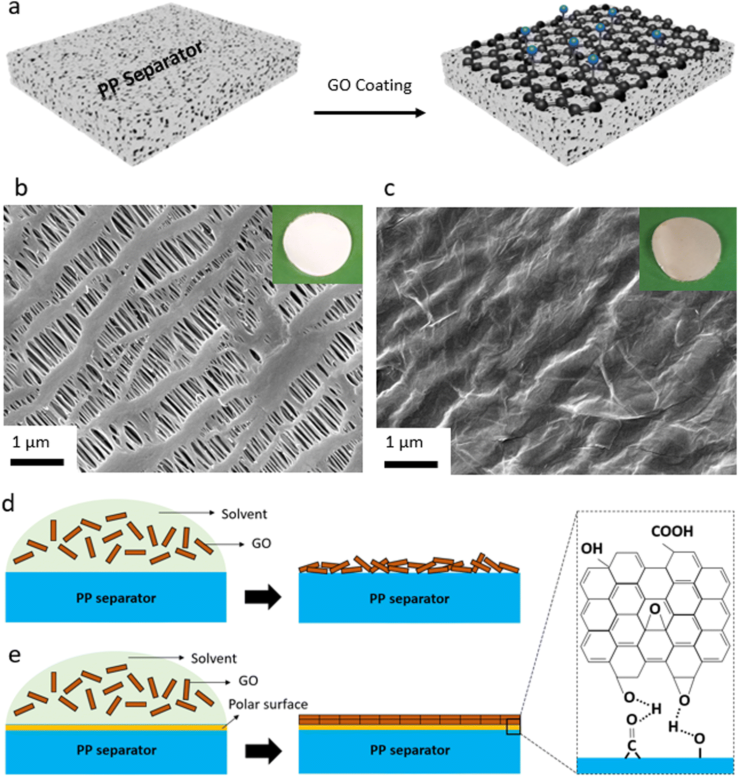 | ||
| Fig. 1 GO-coated separator preparation. (a) Schematic exhibiting coating of the GO membrane onto the plasma-treated PP separator. (b) SEM image of bare PP separator. Inset shows optical image of a typical PP separator. (c) SEM image of the plasma-treated PP separator after GO coating. The inset shows an optical image of the GO-coated separator. Wrinkles further confirm the existence of the uniform, flexible GO layers over the PP separator. Schematic showing GO coating over bare PP separator (d) and plasma-treated PP separator (e). The molecular interactions between the GO layers and functional groups of the PP separator (introduced by the oxygen–plasma), lead to a dense, uniformly aligned GO coating. | ||
Elemental analysis by SEM-EDS also shows that when compared to the bare PP separator (Fig. S6, ESI†), the content of oxygen is higher in the plasma-treated PP separator (Fig. S7, ESI†) and GO-coated PP separator (Fig. S8, ESI†). XPS analysis (Fig. S9–S12, ESI†) is performed to explore the elemental composition of the surface of the PP separator before and after the plasma modification and the GO coating. XPS survey spectra of the control and the plasma-treated PP separators are shown in Fig. S9 (ESI†). In the case of the control PP separator, the XPS spectrum displays the presence of predominantly carbon (C 1s) at around 285 eV. On the other hand, the plasma-treated PP separator shows an intense peak at around 532 eV, corresponding to O 1s, beside the C 1s for the polyolefin membrane. A similar result is found for the sample with GO being coated onto the plasma-treated PP separator. Based on the XPS results, approximately 90% and 10% of the surface of the GO-modified separator is made of carbon and oxygen, respectively.
Deconvolution of the C 1s peak for the plasma-treated PP separator (Fig. S10, ESI†) and GO-modified PP separator (Fig. S11, ESI†) exhibit four peaks at around 282, 283, 284, and 286 eV, corresponding to C–C/C–H, C–O, C![[double bond, length as m-dash]](https://www.rsc.org/images/entities/char_e001.gif) O and –COO groups, respectively. The C–C/C–H peak originate from the control polyolefin separator or the GO membrane, and the other peaks originate from the oxygen-containing functionalities from the GO layer.71 As can be seen, there is a significant O 1s in the modified separators, indicating effective plasma-induced and GO-coating of the polyolefin separator. O 1s XPS of the PP separator, plasma-PP separator, and GO@PP separator is also shown in Fig. S12 (ESI†). A photograph of the water droplet on the control PP separator and the plasma-treated PP separator is also shown in Fig. S13 (ESI†). The high contact angle of the water droplet over the control PP separator indicates the high hydrophobicity and low wettability of the polyolefin separator. On contrary, water droplet gets fully dispersed and diffused into the plasma-treated separator. This further indicates the presence of the oxygen-containing polar functionalities on the surface of the PP separator and hydrophilic nature with high wettability of the modified separator. A similar phenomenon can be expected when the liquid electrolyte (1 M LiPF6 in EC/DEC) is added to the surface of the control and modified PP separators.
O and –COO groups, respectively. The C–C/C–H peak originate from the control polyolefin separator or the GO membrane, and the other peaks originate from the oxygen-containing functionalities from the GO layer.71 As can be seen, there is a significant O 1s in the modified separators, indicating effective plasma-induced and GO-coating of the polyolefin separator. O 1s XPS of the PP separator, plasma-PP separator, and GO@PP separator is also shown in Fig. S12 (ESI†). A photograph of the water droplet on the control PP separator and the plasma-treated PP separator is also shown in Fig. S13 (ESI†). The high contact angle of the water droplet over the control PP separator indicates the high hydrophobicity and low wettability of the polyolefin separator. On contrary, water droplet gets fully dispersed and diffused into the plasma-treated separator. This further indicates the presence of the oxygen-containing polar functionalities on the surface of the PP separator and hydrophilic nature with high wettability of the modified separator. A similar phenomenon can be expected when the liquid electrolyte (1 M LiPF6 in EC/DEC) is added to the surface of the control and modified PP separators.
It is also important to note that the thickness of the GO membrane plays an important role in the kinetics of the Li ions diffusion. In fact, a dense GO coating over separators is reported to slow down the Li ions diffusion, leading to reduced battery performance.7,49 To find the optimal dosage of the GO coating onto the PP separator, we have tested three different GO mass loading of ∼0.02 mg cm−2, ∼0.04 mg cm−2, and ∼0.10 mg cm−2. According to the EIS results (Fig. S14, ESI†) under open circuit voltage (no charge), coating a thin layer of GO over the PP separator is found to lower the interfacial resistance between the Li metal anode and the PP separator. This denotes that the GO layer is beneficial for the transportation of the Li ions.53 However, there is an optimal level at which beyond that level the interfacial resistance would increase. According to the findings, the GO@PP separator with ∼0.04 mg cm−2 GO content shows the lowest interfacial resistance between the Li metal and the PP separator. Consistently, the overpotential value found for the Li‖Li cells with the GO@PP separator (Fig. S15, ESI†) with GO mass loading of ∼0.04 mg cm−2 (∼0.08 mV) is lower than the Li‖Li cells with the lower GO content (∼0.12 mV) or higher GO content (∼0.2 mV), under 1 mA h cm−2 current density. The rate performance of the LMBs with the GO@PP separators made of different GO mass loadings (Fig. S16, ESI†) also shows superior performance for the Li‖LFP cell with the GO mass loading of ∼0.04 mg cm−2. Thus, the GO@PP separator with the GO mass loading of ∼0.04 mg cm−2 is selected for the long-term cycle performance of Li‖Li and Li‖LFP cells. Similar mass loading of the GO was utilized in the case of the PEO SPE.
Li plating behavior in symmetric Li‖Li cells is investigated using the control and GO-modified PP separators to explore the long-term stability of the separators against the Li metal anode. The electrochemical Li deposition at 0.5 mA cm−2 current density with 30 min of Li plating/stripping is displayed in Fig. 2a. As can be seen, the overpotential (voltage polarization) value is lower for the Li deposition in the GO@PP separator. Moreover, there is a constant increase in the voltage polarization in the case of the control separator, which is followed by a sudden drop and finally an internal short-circuit. On the other hand, a stable Li deposition can be observed for the GO@PP separator. As a result, a long-term stability (up to 1000 cycles) against Li metal anode with a uniform voltage polarization can be seen for in the case of the GO@PP separator. Similar behavior is observed for symmetric Li‖Li cells at a higher current density of 1 mA cm−2 (Fig. 2b). While the voltage polarization is constantly increasing in the case of the control PP separator, the voltage polarization is stabile after a slightly decrease in the case of the GO@PP separator. Plasma treatment of the polyolefin separator is also found to partially improve its stability against the Li metal (Fig. S17, ESI†) which can be correlated to the enhance hydrophilicity and wettability of the PP separator upon plasma treatment.72
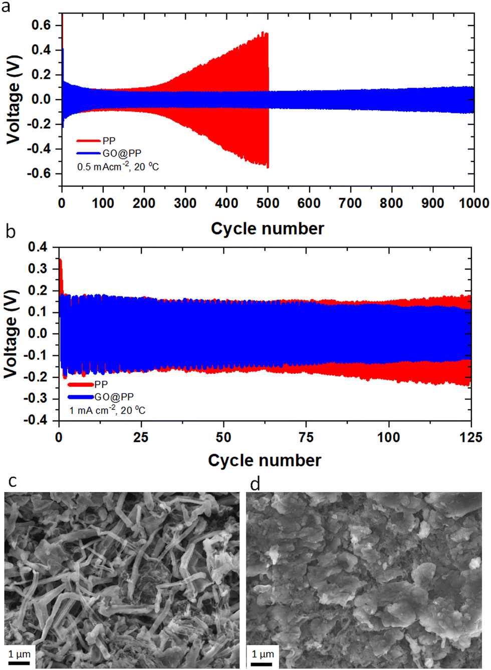 | ||
| Fig. 2 Performance of the symmetric Li‖Li cells with GO coating at the interface of Li metal anode and the PP separator. (a) Overpotential profile of Li‖Li cells made using the control and GO-coated PP separators. The cycling is performed at 0.5 mA cm−2 current density for the Li plating/stripping time of 30 min. (b) Overpotential profile of Li‖Li cells made using the control and GO-coated PP separators. The cycling is performed at 1 mA cm−2 current density for the Li plating/stripping time of 30 min. SEM images of the surface of the Li metal anode after five cycles of Li plating/stripping in the control PP separator (c) and the GO-coated PP separator (d). Li platting is performed at room temperature (∼20 °C) and 0.5 mA cm−2 current density for 30 min of Li plating/stripping. | ||
To explore the Li deposition behavior in the control and GO-modified PP separators, topological and morphological features of the platted Li are investigated using the symmetric Li‖Li cells. As can be seen from Fig. 2c, uneven and extensive Li dendrites grow over the surface of the Li metal anode in the case of the control separator. Indeed, the uneven and random distribution of Li ions through the unmodified separator can expedite local nucleation and growth of the Li metal, leading to the evolution of Li dendrites (Fig. S18, ESI†).7,49 On the other hand, a uniform and dendrite-free Li deposition can be observed in the case of the GO@PP separator (Fig. 2d). This observation illustrates the effective role of the GO membrane in the regulation of the Li ions and the Li metal deposition. In fact, the confinement effect triggered by the GO layer could promote the lateral growth of Li and suppress its dendritic growth. The confinement effect between the GO and Li metal could be triggered by several synergistic factors including strong molecular interactions at GO/Li interface, high mobility of Li ions on the surface of GO, and high surface area of GO for nucleation and growth of Li. It should be also noted that Li ions cannot deposit on an electrically nonconductive or insulating surface of the GO membrane, where there is no accessibility to a considerable extent of electrons for the Li ions reduction to the Li metal.7,73 As a matter of fact, small Li ions can diffuse through the GO membrane via various means including lithiophilic or Li ions hopping sites, inherent GO defective sites, and the gap between GO layers.55,74 AIMD calculations showed that Li ions can pass through the GO layer discontinuities or defective sites. Titan et al., also reported that lithiated 2D materials with vacancies (such as graphene, silicene, phosphorene) can significantly lower the Li ions diffusion barrier from 3.6 eV to 1.98 eV.75 It is also known that the oxygen-containing functionalities of GO membrane can act as lithophilic sites or Li ions hopping sites.34,53,54,76 Using the DFT calculations, high affinity of Li ions to the oxygen atoms of the GO membrane (binding energy between −1.31 eV to −2.25 eV) is reported elsewhere.7 Therefore, the coated GO membrane could only act as a buffer layer for the Li ions regulation and Li metal deposition. The buffering role of the GO membrane, where Li ions tend to eventually pass the membrane is also previously reported.7 Improving the wettability of the PP separator by the oxygen plasma treatment is also found to slightly suppress the dendritic growth of Li (Fig. S19, ESI†).
The effective role of the GO membrane in the Li battery cells with Li‖LFP configuration is further investigated by EIS (Fig. 3a). The semicircle can be correlated to the resistances for the ions diffusion (Rf) and charge transfer resistance (Rct).4,53 A relatively lower resistance against Li ions transport or charge transfer indicates lithiophilicity of the GO membrane and its effective role in facilitating and regulating transport of Li ions.4,53 The rate performance results for Li‖LFP cells (Fig. 3b) also support this phenomenon, whereas the battery cell with the GO@PP separator exhibit a superior rate capability when compared with the battery cell with the bare PP separator. The cycle performance of the LMBs with the control and GO-modified PP separators at different charge/discharge rates are displayed in Fig. 3c, d and Fig. S20 (ESI†). The corresponding voltage profiles are also shown in Fig. S21–S23 (ESI†). Cycle performance of the LMBs with the plasma-treated PP separators and the corresponding voltage profiles are also shown in Fig. S24 and S25 (ESI†). The Li‖LFP cell with the control PP separator delivers a capacity of ∼130 mA h g−1 with ∼35% capacity retention after 1000 cycles at 1C charge/discharge rate (Fig. S21, ESI†). On the contrary, the Li‖LFP cell with the GO-modified PP separator (Fig. S21, ESI†) displays a lower voltage polarization at the same charge/discharge rate with a similar capacity but ∼75% capacity retention after 1600 cycles. We observe similar results for the LMBs cycled at the 2C charge/discharge rate (Fig. 3c and Fig. S22, ESI†). In particular, the Li‖LFP cells with the control and GO-modified PP separators deliver a capacity of ∼120 mA h g−1 at 2C charge/discharge rate. While the LMB with the GO-modified separator shows an ∼70% capacity retention after 2000 cycles, the LMB with the control separator demonstrates ∼30% capacity retention after 1000 cycles. It is also important to note that recent DFT calculations reported by Tian et al. demonstrate that the Li ions diffusion barrier can significantly get decreased after the initial lithiation of 2D materials-based protective layers.75 Hence, the slightly lower capacity and Coulombic efficiency for the initial cycles of the LMBs with the GO-modified PP separator can be ascribed to overcoming the energy barrier by Li ions prior to the establishment of their pathway in the GO membrane.
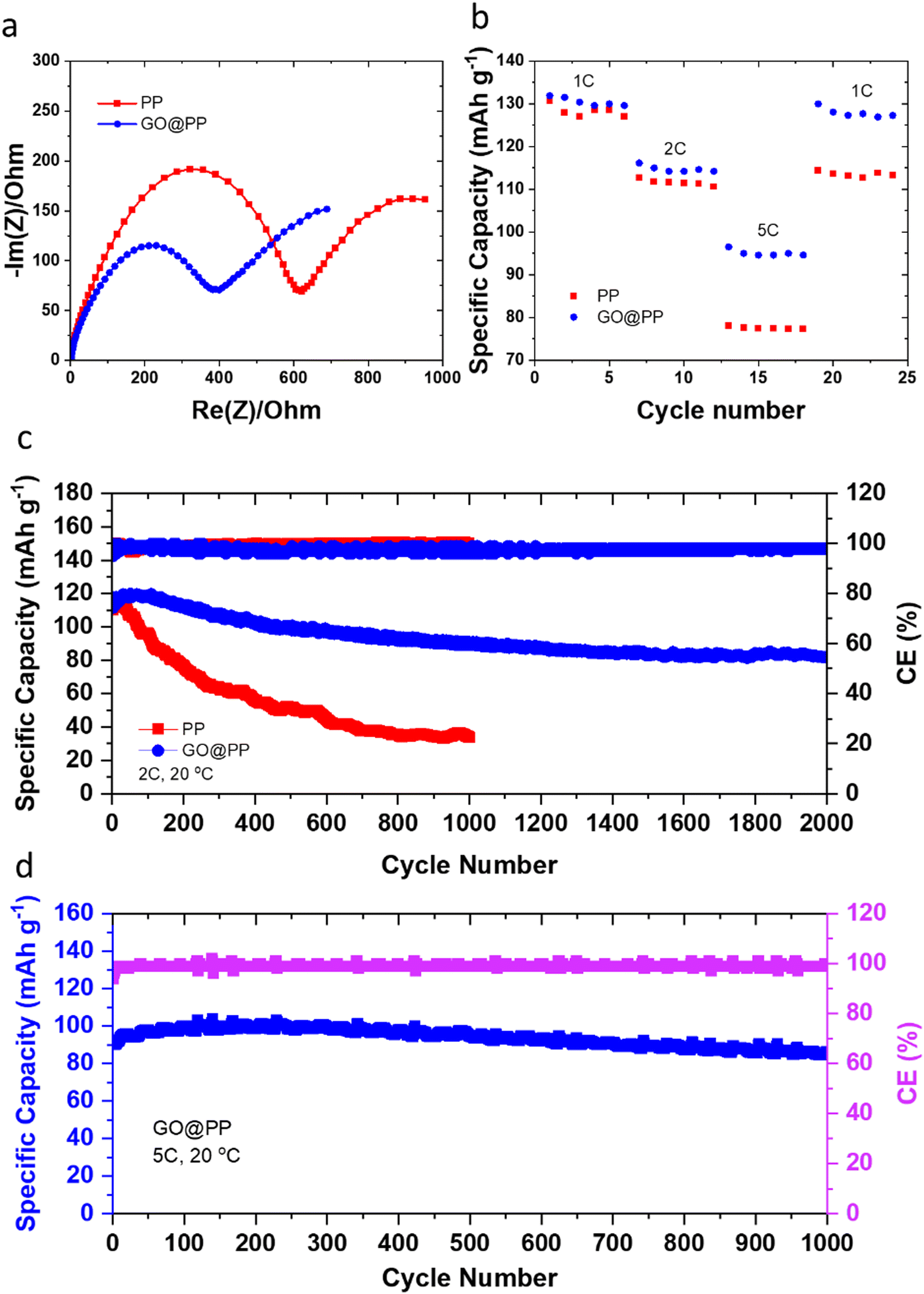 | ||
| Fig. 3 Electrochemical performance of LMBs employing the control and GO-modified polymeric separators. (a) Nyquist plots for the Li‖LFP cells with the control PP separator and the GO-modified PP separator. (b) Rate performance of the Li‖LFP cells with the control PP separator and the GO-modified PP separator. (c) Long-term cycle performance of the Li‖LFP cells with the control and the GO-modified PP separators at 2C charge/discharge rate. (d) Long-term cycle performance of the Li‖LFP cell with the GO-modified PP separator at 5C charge/discharge rate. | ||
The long-term fast rate charge capability of the LMBs with the GO@PP separator is also investigated at 5C charge/discharge rate (Fig. 3d and Fig. S23, ESI†). The cycle performance of the LMBs with the GO@PP at 5C charge/discharge rate indicate a capacity of ∼100 mA h g−1 with ∼90% capacity retention after 1000 cycles. These results illustrate the high capability of the GO@PP separator in development of fast rate charge, long lifespan LMBs. It is also found that the plasma treatment of the polyolefin separator leads to a partial improvement in the cycle performance of the LMBs (Fig. S24 and S25, ESI†). In particular, the Li‖LFP cell with the plasma-treated PP separator shows a capacity of ∼120 mA h g−1 at 2C charge/discharge rate with a capacity retention of ∼50% after 1000 cycles at 2C charge/discharge rate (Fig. S25, ESI†). Furthermore, rate cyclability of the Li‖LFP cell with the commercial LFP (cathode mass loading of ∼7.1 mg cm−2) indicates high capability of the GO@PP separator for LMBs with high mass load LFP cathode (Fig. S26, ESI†). The Li‖LFP cell with the commercial LFP cathode film also delivers a specific capacity of ∼170 mA h g−1 with full capacity retention after 100 cycles at 0.2C charge/discharge rate (Fig. S26, ESI†). Table S1 (ESI†) also summarizes the cyclability and lifespan of LMBs with functional separators reported during the last years. As can be seen, the GO@PP separator reported in this study significantly enhanced the charge/discharge rate capability and lifespan of LMBs.
We have also explored the effective role of the GO layer in LMBs with SPEs. Considering various issues concerning the liquid electrolytes (e.g. dendritic growth of Li, solvent leakage, environmental concerns, thermal runaway) solid-state electrolytes, particularly SPEs, have acquired a tremendous interest in LMBs in the last years.77,78 This is due to many advantages of polymer electrolytes including low cost, lightweight, satisfactory mechanical properties, inherent safety, high cathodic stability, and accessibility toward roll-to-roll manufacturing processes and large-scale production.79 Yet, Li dendritic growth and instability against the Li metal anode are among major issues concerning polymer electrolytes, resulting in capacity loss during battery operation. Herein, we utilized the same approach developed for the PP separator and coated a thin layer of GO onto the PEO-based SPE. The GO layer would allow for the confinement effect, enforcing lateral growth of electrochemically deposited Li, and at the same time, acting as conductive interface to avoid direct contact between the Li metal and the polymer electrolyte. While GO has been widely used as a filler in SPEs,58,80–85 our work is a unique report on the spray-coated GO@PEO SPE (Fig. 4a). Due to the polar nature of PEO, GO was directly spray-coated onto SPE separators. SEM images of the control and GO-modified SPEs (Fig. 4b and c) show that the GO layers are uniformly distributed over the dense structure of the SPE, creating a strong connection between the GO sheets. A schematic illustration of the GO coating onto the surface of PEO SPE is shown in Fig. 4d. Coating of the GO layer with polar nature over the polar PEO SPE leads to strong chemical interactions between the separator and the GO layers, ensuring a dense, uniformly aligned GO coating.
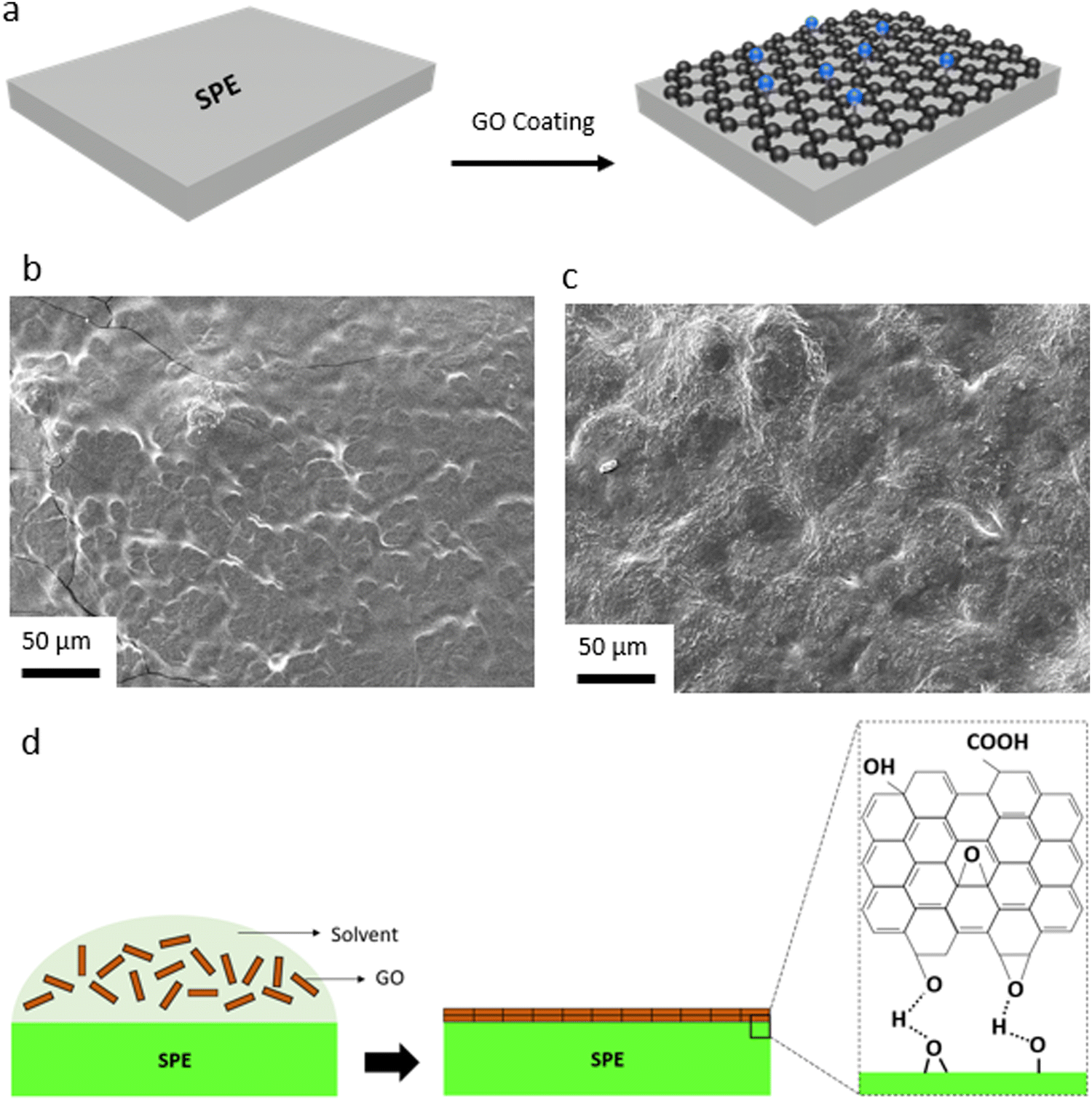 | ||
| Fig. 4 (a) Schematic exhibiting coating of the GO membrane onto the SPE. (b) SEM image of bare SPE. (c) SEM image of the GO-coated SPE. (d) Schematic illustrating the molecular interactions between the GO and functional groups of the SPE, leading to uniform GO coating. | ||
Li plating/stripping behavior in symmetric Li‖Li cells is explored using the control and GO-modified SPE to evaluate the long-term stability of the SPEs against Li metal (Fig. S27, ESI†). As can be seen, the overpotential (voltage polarization) value is lower in the case of the GO-coated SPE, when compared to the control SPE. Moreover, a stable Li deposition can be observed for the GO-modified SPE, which leads to a long-term stability against Li metal anode. A similar Li deposition behavior is observed in the case of the control and GO-modified SPEs when compared to the GO-coated PP separators (Fig. S28, ESI†). While an uneven and dendritic-like Li growth can be observed in the case of the control SPE (Fig. S28a, ESI†), a uniform, 2D-like Li electrodeposition could be observed in the case of the GO@SPE (Fig. S28b, ESI†).
Nyquist plots (Fig. 5a) for the LMBs with the GO-modified SPE demonstrate a relatively lower resistance against ion transport or charge transfer, indicating lithiophilicity of the GO membrane and its effective role in facilitating Li ions transport.4,53 Rate performance (Fig. 5b) of the Li‖LFP cell with the GO-modified SPE shows a superior performance when compared to the Li‖LFP cell with the control SPE. Furthermore, the cycle performance of the LMBs with the control and GO-modified SPEs are displayed in Fig. 5c. The Li‖LFP cell with the control SPE (Fig. 5c) delivers a capacity of ∼100 mA h g−1 with around 30% capacity retention after 100 cycles at 1C charge/discharge rate. On the contrary, the Li‖LFP cell with the GO-modified SPE (Fig. 5c) displays a lower voltage polarization at the same charge/discharge rate with a capacity of ∼115 mA h g−1 and ∼85% capacity retention after 200 cycles. These findings further confirm the universality and effective role of GO coating in enhancing the cyclability and lifespan of LMBs with liquid and polymer electrolytes. Table S2 (ESI†) and Fig. 5d also summarize the cyclability and lifespan of LMBs with solid-state polymer electrolytes reported during the recent years. As can be seen, the GO@SPE reported in this study significantly improved the charge/discharge rate capability and lifespan of LMBs. The superior fast rate and cycle performance of LMBs with the aligned GO is correlated to the confinement effect, promoting the lateral growth of Li. The confinement effect between the aligned GO and Li metal could be triggered by several synergistic factors including strong molecular interactions at GO/Li interface, high mobility of Li ions on the surface of GO, and high surface area of GO for nucleation and growth of Li.
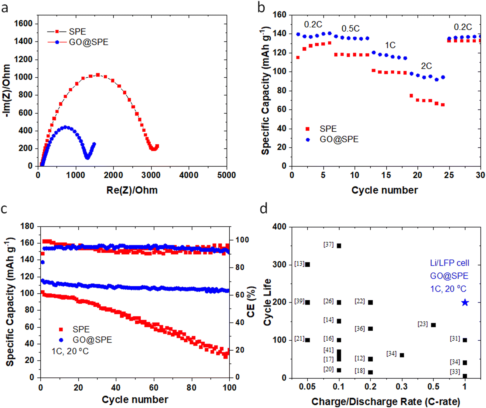 | ||
| Fig. 5 (a) Nyquist plots for the Li‖LFP cells with the control SPE and the GO-modified SPE. (b) Rate performance of the Li‖LFP cells with the control SPE and the GO-modified SPE. (c) Long-term cycle performance of the Li‖LFP cells with the control and the GO-modified SPEs at 1C charge/discharge rate. All tests are performed at room temperature (∼20 °C). (d) The comparison of cycling performance of LMBs using solid-state electrolytes reported in the literature (shown in black color) as outlined in Table S2 (ESI†) versus data reported in this work (blue colored star). | ||
In summary, we report a significant improvement in rate of charge/discharge of the LMBs and their lifespan with the GO-modified separators (both PP and SPE separators). This could be attributed to the confinement effect between the GO and Li metal. The confinement effect could be triggered by several synergistic factors including strong molecular interactions at GO/Li interface, high mobility of Li ions on the surface of GO, and high surface area of GO for nucleation and growth of Li. A schematic illustration of the proposed mechanism is shown in Fig. 6. Strong molecular interactions (e.g. van der Waals and covalent bonding) at the interface of the Li metal anode and the GO layer is one of the main contributing factors. Based on the XPS results, approximately 90% and 10% of the surface of the GO-modified separator is made of carbon and oxygen, respectively. Thus, and considering the coexistence of graphitic carbon and oxygen groups in the GO layer, both van der Waals bonding (between the graphitic carbon and the Li metal)40 and covalent bonding (between the oxygen groups of the GO and Li metal)36 can be formed. It is known that 2D materials could confine and enforce 2D growth of metallic and nonmetallic materials via forming strong van der Waals or covalent bonding with them.37–40,42 Enforced 2D growth of tin, indium, and gallium metals at interface of graphene and silicon carbide is reported elsewhere,40 with these metals forming van der Waals bonding and covalent bonding with the graphene and silicon carbide, respectively. Using atomic force microscopy indentation, Khestanova et al.86 were able to measure van der Waals pressure exerted by the graphene membrane and MoS2 membrane on trapped material, which could reach to an order of 1 GPa at nanoscale. This ultrahigh pressure is beyond yield strength of the Li metal,87 denoting that the confinement effect could enforce 2D growth of electrochemically deposited Li, as observed by SEM (Fig. 2d). A strong covalent bonding between the oxygen-containing groups of GO layer and Li metal is also known.36,41,44,75 The formation of strong covalent Li–O bonds between the GO and Li metal is reported elsewhere.36,44 These covalent Li–O bonds are also shown to facilitate the Li+ ions formation when leaving the graphene monoxide layer, which could be of substantial benefit for fast charging Li batteries.36 Li adsorption on GO layer is significantly stronger than its adsorption on the graphene layer due to stronger Li–O bond when compared to Li–C bond44 and the coexistence of these bonds can further strengthen the GO–Li bond at the interface. Our DFT calculations further illustrate strong affinity of the Li ion to the oxygen-containing groups of the GO layer, which is favored by −1.83 eV. Therefore, we believe that the enhanced electrochemical performance of LMBs upon the GO coating could be correlated with the confinement effect between the GO layer and Li metal.
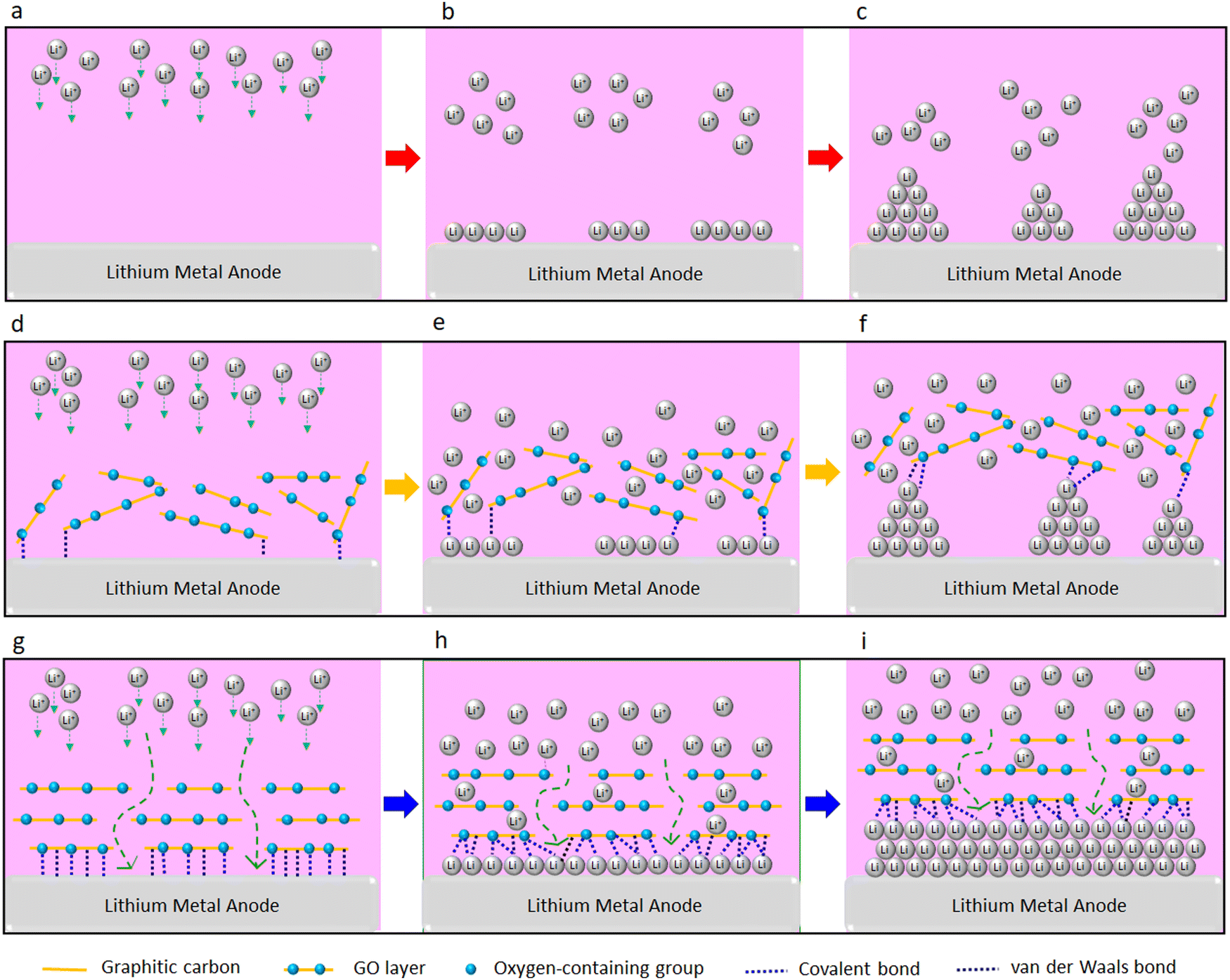 | ||
| Fig. 6 The comparison between Li deposition at the surface of Li (a–c) without GO, (d and e) with non-aligned GO, and (g–i) with aligned GO. (a–c) Without GO:Li ions deposition leads to uneven and anisotropic (dendritic) growth of electrochemically deposited Li metal. (d–f) With non-aligned GO: weak molecular interactions between the randomly oriented GO layers and Li metal does not effectively suppress the uneven and anisotropic (dendritic) growth of electrochemically deposited Li metal. (g–i) With aligned GO: strong molecular interactions between the GO surface and Li metal could lead to nanoscale confinement preventing the anisotropic growth of Li dendrites, and enforcing lateral (nondendritic) growth of electrochemically deposited Li. | ||
Furthermore, it is reported that the GO membrane stores the Li ions for a limited time prior to their release to the Li metal surface.7 This limited Li ions storage time delays the Li ions transfer to the Li metal surface, which can prevent the “tip effect,” leading to an even Li deposition on the Li electrode surface.7 At the same time, superflexibility7 and high mechanical strength7 of GO could act as a strong physical barrier, further suppressing the Li anisotropic growth of Li and enforcing its lateral growth. Overall, we believe that confinement effect of 2D materials can be a promising strategy to enable fast rechargeable Li metal batteries.
4. Conclusion
In summary, we demonstrated that the confinement effect of parallelly-aligned GO at Li metal surface could be an effective strategy to suppress the dendritic growth of electrochemically deposited Li. This nondendritic growth of Li enables fast charge/discharge capability of the Li batteries and their prolonged lifespan. The effectiveness of aligned GO in suppression of lithium dendrites is shown for both liquid electrolyte cells with porous PP separators and solid polymer electrolytes made of PEO. In order to create aligned GO, porous PP separators were treated with plasma. Electrochemical tests exhibit a significantly enhanced Li-metal anode stability and cycle life of LMBs after the GO coating. The liquid electrolyte Li‖LFP cells with the aligned GO could cycle at high charge/discharge rate of 5C for 1000 cycles with ∼90% capacity retention. Such combined high rate and cycle performance has not been achieved in the literature (Table S1, ESI†).A similar improvement in the charge/discharge rate of LMBs with the SPEs is observed with GO layers at the Li metal interface. The SPE-based Li‖LFP cell with GO showed ∼85% capacity retention after 200 cycles at 1C exceeding the previously reported room temperature rate cyclability of solid polymer Li‖LFP cells (Table S2, ESI†). The significant improvement in electrochemical performance of LMBs is discussed considering the confinement effect between the GO and Li metal. This study offers a new opportunity to utilize the confinement effect of two-dimensional materials for the development of fast rate rechargeable Li batteries.
Author contributions
This study is conceptualized by V. J. and R. S.-Y.; V. J. designed and performed the experiments, and prepared the manuscript, figures, and ESI;† V. Y. and F. M. performed the DFT calculations; A. G. performed electron microscopy, and XPS tests. All authors discussed the results and commented on the manuscript.Conflicts of interest
The authors declare no conflict of interest.Acknowledgements
R. Shahbazian-Yassar acknowledges the financial support from the National Science Foundation (NSF-CBET award no. 1805938). The present DFT calculations were performed on the High-Performance Computing Cluster Extreme at the University of Illinois at Chicago. The authors also acknowledge the Battery Technology Laboratory of the College of Engineering and Research Resources Center (RRC) at the University of Illinois at Chicago (UIC) especially Director of Electron Microscopy Core, Dr Fengyuan Shi, and Northwestern University Atomic and Nanoscale Characterization Center (NUANCE) especially NUANCE-Keckll manager, Dr Xinqi Chen.References
- J. Jang, J. Oh, H. Jeong, W. Kang and C. Jo, Materials, 2020, 13, 1–37 Search PubMed.
- Z. Li, J. Huang, B. Yann Liaw, V. Metzler and J. Zhang, J. Power Sources, 2014, 254, 168–182 CrossRef CAS.
- V. Jabbari, V. Yurkiv, M. G. Rasul, M. Cheng, P. Griffin, F. Mashayek and R. Shahbazian-Yassar, Small, 2021, 2102666, 1–11 Search PubMed.
- V. Jabbari, V. Yurkiv, M. G. Rasul, M. T. Saray, R. Rojaee, F. Mashayek and R. Shahbazian-Yassar, Energy Storage Mater., 2022, 46, 352–365 CrossRef.
- G. Wan, F. Guo, H. Li, Y. Cao, X. Ai, J. Qian, Y. Li and H. Yang, ACS Appl. Mater. Interfaces, 2018, 10(1), 593–601 CrossRef CAS PubMed.
- M. Armand, Nature, 2001, 414, 359–367 CrossRef PubMed.
- T. Foroozan, F. A. Soto, V. Yurkiv, S. Sharifi-Asl, R. Deivanayagam, Z. Huang, R. Rojaee, F. Mashayek, P. B. Balbuena and R. Shahbazian-Yassar, Adv. Funct. Mater., 2018, 28, 1–13 CrossRef.
- X. B. Cheng, R. Zhang, C. Z. Zhao and Q. Zhang, Chem. Rev., 2017, 117, 10403–10473 CrossRef CAS PubMed.
- C. Wang, Y. Yang, X. Liu, H. Zhong, H. Xu, Z. Xu, H. Shao and F. Ding, ACS Appl. Mater. Interfaces, 2017, 9, 13694–13702 CrossRef CAS PubMed.
- S. Tang, G. Chen, F. Ren, H. Wang, W. Yang, C. Zheng, Z. Gong and Y. Yang, J. Mater. Chem. A, 2021, 9, 3576–3583 RSC.
- D. Cao, X. Sun, Q. Li, A. Natan, P. Xiang and H. Zhu, Matter, 2020, 3, 57–94 CrossRef.
- P. Shi, F. Liu, Y. Feng, J. Zhou, X. Rui and Y. Yu, Small, 2020, 16, 2001989 CrossRef CAS PubMed.
- S. J. Chang, C. H. Chen and K. C. Chen, Phys. Chem. Chem. Phys., 2022, 11086–11095 RSC.
- P. Zou, Y. Wang, S. W. Chiang, X. Wang, F. Kang and C. Yang, Nat. Commun., 2018, 9(464) DOI:10.1038/s41467-018-02888-8.
- H. Xu, Y. Li, A. Zhou, N. Wu, S. Xin, Z. Li and J. B. Goodenough, Nano Lett., 2018, 18, 7414–7418 CrossRef CAS PubMed.
- D. Rehnlund, F. Lindgren, S. Böhme, T. Nordh, Y. Zou, J. Pettersson, U. Bexell, M. Boman, K. Edström and L. Nyholm, Energy Environ. Sci., 2017, 10, 1350–1357 RSC.
- C. L. Tsai, V. Roddatis, C. V. Chandran, Q. Ma, S. Uhlenbruck, M. Bram, P. Heitjans and O. Guillon, ACS Appl. Mater. Interfaces, 2016, 8, 10617–10626 CrossRef CAS PubMed.
- M. Wu, Z. Wen, Y. Liu, X. Wang and L. Huang, J. Power Sources, 2011, 196, 8091–8097 CrossRef CAS.
- Z. Wang, Y. Wang, C. Wu, W. K. Pang, J. Mao and Z. Guo, Chem. Sci., 2021, 12, 8945–8966 RSC.
- N. Tapia-Ruiz, A. G. Gordon, C. M. Jewell, H. K. Edwards, C. W. Dunnill, J. M. Blackman, C. P. Snape, P. D. Brown, I. MacLaren, M. Baldoni, E. Besley, J. J. Titman and D. H. Gregory, Nat. Commun., 2020, 11, 1–8 Search PubMed.
- L. Lin, F. Liang, K. Zhang, H. Mao, J. Yang and Y. Qian, J. Mater. Chem. A, 2018, 6, 15859–15867 RSC.
- S. Li, Q. Liu, X. Wang, Q. Wu, L. Fan, W. Zhang, Z. Shen, L. Wang, M. Ling and Y. Lu, ACS Mater. Lett., 2020, 2, 1–8 CrossRef.
- Y. Wang, J. Travas-Sejdic and R. Steiner, Solid State Ionics, 2002, 148, 443–449 CrossRef CAS.
- D. W. Kim, J. M. Ko, J. H. Chun, S. H. Kim and J. K. Park, Electrochem. Commun., 2001, 3, 535–538 CrossRef CAS.
- S. S. Zhang, J. Power Sources, 2007, 164, 351–364 CrossRef CAS.
- Z. Zhang, S. Yi, Y. Wei, H. Bian, R. Wang and Y. Min, Polymers, 2019, 11, 1–10 CrossRef.
- Y. J. Zhang, X. H. Xia, D. H. Wang, X. L. Wang, C. D. Gu and J. P. Tu, RSC Adv., 2016, 6, 11657–11664 RSC.
- D. Lin, Y. Liu, Z. Liang, H. W. Lee, J. Sun, H. Wang, K. Yan, J. Xie and Y. Cui, Nat. Nanotechnol., 2016, 11, 626–632 CrossRef CAS PubMed.
- G. Hu, C. Xu, Z. Sun, S. Wang, H. M. Cheng, F. Li and W. Ren, Adv. Mater., 2016, 28, 1603–1609 CrossRef CAS PubMed.
- T. T. Zuo, X. W. Wu, C. P. Yang, Y. X. Yin, H. Ye, N. W. Li and Y. G. Guo, Adv. Mater., 2017, 29, 1–6 Search PubMed.
- X. B. Cheng, H. J. Peng, J. Q. Huang, R. Zhang, C. Z. Zhao and Q. Zhang, ACS Nano, 2015, 9, 6373–6382 CrossRef CAS PubMed.
- D. Zhang, Y. Zhou, C. Liu and S. Fan, Nanoscale, 2016, 8, 11161–11167 RSC.
- K. Yan, H. W. Lee, T. Gao, G. Zheng, H. Yao, H. Wang, Z. Lu, Y. Zhou, Z. Liang, Z. Liu, S. Chu and Y. Cui, Nano Lett., 2014, 14, 6016–6022 CrossRef CAS PubMed.
- R. Zhang, X. R. Chen, X. Chen, X. B. Cheng, X. Q. Zhang, C. Yan and Q. Zhang, Angew. Chem., Int. Ed., 2017, 56, 7764–7768 CrossRef CAS PubMed.
- A. R. O. Raji, R. Villegas Salvatierra, N. D. Kim, X. Fan, Y. Li, G. A. L. Silva, J. Sha and J. M. Tour, ACS Nano, 2017, 11, 6362–6369 CrossRef CAS PubMed.
- D. Radevych, M. Gajdardziska-Josifovska, C. J. Hirschmugl and M. Weinert, J. Phys. Chem. C, 2021, 125, 11820–11827 CrossRef CAS.
- Z. Y. Al Balushi, K. Wang, R. K. Ghosh, R. A. Vilá, S. M. Eichfeld, J. D. Caldwell, X. Qin, Y. C. Lin, P. A. Desario, G. Stone, S. Subramanian, D. F. Paul, R. M. Wallace, S. Datta, J. M. Redwing and J. A. Robinson, Nat. Mater., 2016, 15, 1166–1171 CrossRef CAS PubMed.
- K. Mustonen, C. Hofer, P. Kotrusz, A. Markevich, M. Hulman, C. Mangler, T. Susi, T. J. Pennycook, K. Hricovini, C. Richter, J. C. Meyer, J. Kotakoski and V. Skákalová, Adv. Mater., 2022, 34(9), 2106922 CrossRef CAS PubMed.
- K. S. Novoselov, A. Mishchenko, O. A. Carvalho and A. H. Castro Neto, Science, 2016, 353(6298) DOI:10.1126/science.aac9439.
- N. Briggs, B. Bersch, Y. Wang, J. Jiang, R. J. Koch, N. Nayir, K. Wang, M. Kolmer, W. Ko, A. De La Fuente Duran, S. Subramanian, C. Dong, J. Shallenberger, M. Fu, Q. Zou, Y. W. Chuang, Z. Gai, A. P. Li, A. Bostwick, C. Jozwiak, C. Z. Chang, E. Rotenberg, J. Zhu, A. C. T. van Duin, V. Crespi and J. A. Robinson, Nat. Mater., 2020, 19, 637–643 CrossRef CAS PubMed.
- X. Chen, X.-R. Chen, T.-Z. Hou, B.-Q. Li, X.-B. Cheng, R. Zhang and Q. Zhang, Sci. Adv., 2019, 5(2) DOI:10.1126/sciadv.aau7728.
- M. Kühne, F. Börrnert, S. Fecher, M. Ghorbani-Asl, J. Biskupek, D. Samuelis, A. V. Krasheninnikov, U. Kaiser and J. H. Smet, Nature, 2018, 564, 234–239 CrossRef PubMed.
- X. X. Ma, X. Chen, Y. K. Bai, X. Shen, R. Zhang and Q. Zhang, Small, 2021, 17, 1–7 Search PubMed.
- N. Dimakis, I. Salas, L. Gonzalez, O. Vadodaria, K. Ruiz and M. I. Bhatti, Molecules, 2019, 24, 1–28 CrossRef PubMed.
- J. J. Shao, W. Lv and Q. H. Yang, Adv. Mater., 2014, 26, 5586–5612 CrossRef CAS PubMed.
- G. Eda and M. Chhowalla, Adv. Mater., 2010, 22, 2392–2415 CrossRef CAS PubMed.
- T. H. Tight, Science, 2012, 335, 442–444 CrossRef PubMed.
- R. K. Joshi, P. Carbone, F. C. Wang, V. G. Kravets, Y. Su, I. V. Grigorieva, H. A. Wu, A. K. Geim and R. R. Nair, Science, 2014, 343, 752–754 CrossRef CAS PubMed.
- Y. Zhang, L. Miao, J. Ning, Z. Xiao, L. Hao, B. Wang and L. Zhi, 2D Mater., 2015, 2(2), 024013 CrossRef.
- X. Liu, K. Song, C. Lu, Y. Huang, X. Duan, S. Li and Y. Ding, J. Membr. Sci., 2018, 555, 1–6 CrossRef CAS.
- H. Chen, Y. Yang, D. T. Boyle, Y. K. Jeong, R. Xu, L. S. de Vasconcelos, Z. Huang, H. Wang, H. Wang, W. Huang, H. Li, J. Wang, H. Gu, R. Matsumoto, K. Motohashi, Y. Nakayama, K. Zhao and Y. Cui, Nat. Energy, 2021, 6, 790–798 CrossRef CAS.
- J. Li, Z. Xiao, A. Chen, W. Zhang, D. Zhu, Y. Jin, Q. Mao, G. Wang, J. He and Y. Xia, Front. Energy Res., 2020, 8, 1–19 CrossRef.
- T. Lei, W. Chen, W. Lv, J. Huang, J. Zhu, J. Chu, C. Yan, C. Wu, Y. Yan, W. He, J. Xiong, Y. Li, C. Yan, J. B. Goodenough and X. Duan, Joule, 2018, 2, 2091–2104 CrossRef CAS.
- Y. Pan, J. Hao, X. Zhu, Y. Zhou and S. L. Chou, Inorg. Chem. Front., 2018, 5, 1869–1875 RSC.
- J. Q. Huang, T. Z. Zhuang, Q. Zhang, H. J. Peng, C. M. Chen and F. Wei, ACS Nano, 2015, 9, 3002–3011 CrossRef CAS PubMed.
- S. Wang, F. Gao, Y. Zhao, N. Liu, T. Tan and X. Wang, Nanoscale Res. Lett., 2018, 13, 377 CrossRef PubMed.
- Z. Hu, X. Zhang and S. Chen, J. Power Sources, 2020, 477, 228754 CrossRef CAS.
- J. Wen, Q. Zhao, X. Jiang, G. Ji, R. Wang, G. Lu, J. Long, N. Hu and C. Xu, ACS Appl. Energy Mater., 2021, 4, 3660–3669 CrossRef CAS.
- M. Bai, K. Xie, K. Yuan, K. Zhang, N. Li, C. Shen, Y. Lai, R. Vajtai, P. Ajayan and B. Wei, Adv. Mater., 2018, 30, 1–7 Search PubMed.
- J. Bobnar, M. Lozinšek, G. Kapun, C. Njel, R. Dedryvère, B. Genorio and R. Dominko, Sci. Rep., 2018, 8, 1–10 CAS.
- P. Yao, Q. Chen, Y. Mu, J. Liang, X. Li, X. Liu, Y. Wang, B. Zhu and J. Zhu, Mater. Chem. Front., 2019, 3, 339–343 RSC.
- Y. J. Zhang, X. H. Xia, X. L. Wang, C. D. Gu and J. P. Tu, RSC Adv., 2016, 6, 66161–66168 RSC.
- X. Wu, N. Liu, Z. Guo, M. Wang, Y. Qiu, D. Tian, B. Guan, L. Fan and N. Zhang, Energy Storage Mater., 2020, 28, 153–159 CrossRef.
- H. Xiao, T. Zhang, X. Liang and Q. Gao, Electrochim. Acta, 2021, 391, 138910 CrossRef CAS.
- Y. Yang, L. Ai, S. Yu, J. He, T. Xu, D. Chen and L. Shen, ACS Appl. Energy Mater., 2022, 5(12), 15666–15672 CrossRef CAS.
- L. K. Zhang, H. M. Xu, M. X. Jing, L. X. Li, H. Yang and X. Q. Shen, ACS Appl. Nano Mater., 2021, 4, 9471–9478 CrossRef CAS.
- S. Tsuneda, K. Saito, S. Furusaki, T. Sugo and K. Makuuchi, Ind. Eng. Chem. Res., 1993, 32, 1464–1470 CrossRef CAS.
- G. Kresse and J. Furthmüller, Phys. Rev. B: Condens. Matter Mater. Phys., 1996, 54, 11169–11186 CrossRef CAS PubMed.
- J. P. Perdew, J. A. Chevary, S. H. Vosko, K. A. Jackson, M. R. Pederson, D. J. Singh and C. Fiolhais, Phys. Rev. B: Condens. Matter Mater. Phys., 1993, 48, 4978 CrossRef CAS PubMed.
- J. P. Perdew, K. Burke and M. Ernzerhof, Phys. Rev. Lett., 1996, 77, 3865–3868 CrossRef CAS PubMed.
- V. Švorčík, K. Kolářová, P. Slepička, A. Macková, M. Novotná and V. Hnatowicz, Polym. Degrad. Stab., 2006, 91, 1219–1225 CrossRef.
- J. Y. Kim, Y. Lee and D. Y. Lim, Electrochim. Acta, 2009, 54, 3714–3719 CrossRef CAS.
- C. Gómez-Navarro, R. T. Weitz, A. M. Bittner, M. Scolari, A. Mews, M. Burghard and K. Kern, Nano Lett., 2007, 7, 3499–3503 CrossRef PubMed.
- P. Sun, F. Zheng, M. Zhu, Z. Song, K. Wang, M. Zhong, D. Wu, R. B. Little, Z. Xu and H. Zhu, ACS Nano, 2014, 8, 850–859 CrossRef CAS PubMed.
- H. Tian, Z. W. Seh, K. Yan, Z. Fu, P. Tang, Y. Lu, R. Zhang, D. Legut, Y. Cui and Q. Zhang, Adv. Energy Mater., 2017, 7(13), 1602528 CrossRef.
- D. Dai, Y. Chen, B. Chen, J. Qiu, B. Li and B. Wang, J. Electrochem. Energy Convers. Storage, 2022, 19, 1–7 Search PubMed.
- D. Dong, B. Zhou, Y. Sun, H. Zhang, G. Zhong, Q. Dong, F. Fu, H. Qian, Z. Lin, D. Lu, Y. Shen, J. Wu, L. Chen and H. Chen, Nano Lett., 2019, 19, 2343–2349 CrossRef CAS PubMed.
- X. Chen, W. He, L. X. Ding, S. Wang and H. Wang, Energy Environ. Sci., 2019, 12, 938–944 RSC.
- S. Choudhury, S. Stalin, D. Vu, A. Warren, Y. Deng, P. Biswal and L. A. Archer, Nat. Commun., 2019, 10, 1–8 CrossRef PubMed.
- K. Fu, Y. Wang, C. Yan, Y. Yao, Y. Chen, J. Dai, S. Lacey, Y. Wang, J. Wan, T. Li, Z. Wang, Y. Xu and L. Hu, Adv. Mater., 2016, 28, 2587–2594 CrossRef CAS PubMed.
- M. Kammoun, S. Berg and H. Ardebili, Nanoscale, 2015, 7, 17516–17522 RSC.
- X. Wang, H. Zhao, N. Deng, Y. Li, R. Yu, Y. Wen, W. Kang and B. Cheng, Sustainable Energy Fuels, 2022, 6, 386–397 RSC.
- H. Bashirpour-Bonab, Int. J. Energy Res., 2022, 46, 15793–15803 CrossRef CAS.
- Z. Hu, X. Zhang, J. Liu and Y. Zhu, Front. Chem., 2020, 8, 1–8 CrossRef PubMed.
- Q. Wang, Z. Zhang, F. Shen, B. Zhao and X. Han, Mater. Express, 2019, 9, 1055–1061 CrossRef CAS.
- E. Khestanova, F. Guinea, L. Fumagalli, A. K. Geim and I. V. Grigorieva, Nat. Commun., 2016, 7, 1–10 Search PubMed.
- C. Xu, Z. Ahmad, A. Aryanfar, V. Viswanathan and J. R. Greer, Proc. Natl. Acad. Sci. U. S. A., 2017, 114, 57–61 CrossRef CAS PubMed.
Footnote |
| † Electronic supplementary information (ESI) available. See DOI: https://doi.org/10.1039/d3ya00083d |
| This journal is © The Royal Society of Chemistry 2023 |