
The effect of tensile strain in Pd–Ni core–shell nanocubes with tuneable shell thickness on urea electrolysis selectivity†
Jeongeon
Kim
ab,
Xenia
Medvedeva
a,
Jury J.
Medvedev
 a,
Cheongwon
Bae
b,
Juyeong
Kim
*b and
Anna
Klinkova
*a
a,
Cheongwon
Bae
b,
Juyeong
Kim
*b and
Anna
Klinkova
*a
aDepartment of Chemistry, University of Waterloo, 200 University Avenue West, Waterloo, Ontario N2L 3G1, Canada. E-mail: aklinkova@uwaterloo.ca
bDepartment of Chemistry and Research Institute of Natural Sciences, Gyeongsang National University, Jinju 52828, South Korea. E-mail: chris@gnu.ac.kr
First published on 26th January 2023
Abstract
Expanding our understanding of the structure-performance relationship in nanoscale electrocatalysts for urea electrolysis is crucial for efficient urea waste treatment and concomitant cathodic hydrogen production or CO2 reduction. Here, we elucidate the effect of the lattice strain in Pd–Ni core–shell nanocubes on the dominance of urea overoxidation pathway.
 Anna Klinkova | Dr Anna Klinkova obtained her PhD in Chemistry from the University of Toronto in 2015. She was then a Connaught Postdoctoral Fellow conducting research focused on carbon dioxide electroreduction. Since 2017, she has been an Assistant Professor of Chemistry at the University of Waterloo, and her team's research has been focused on developing synthetic approaches to advanced nanomaterials for applications in sustainable energy and catalysis. Her independent research work has been recognized with several awards including the International Association of Colloid and Interface Scientists (IACIS) Emerging Investigator Award and Outstanding Early-Career Achievements Award by Nano Ontario. |
Urea is one of key molecules for modern society with a variety of applications, including use as an agricultural fertilizer, a precursor for the synthesis of melamine, formaldehyde resins and barbiturates, and a diesel engine additive.1–4 These sectors continuously emit urea-enriched wastewater, which then enters the environment.5,6 Additional urea contamination arises from human and animal metabolism.1,5 Although urea itself is a nontoxic molecule, it decomposes in aquatic systems to form ammonia, which causes algae blooms and further undergoes oxidation in the atmosphere to hazardous nitrogen oxides.7 Therefore, the treatment of urea laden wastewater is essential to minimize its negative impact on ecosystems.7
The electrochemical urea oxidation reaction (UOR) has attracted a lot of attention as a green alternative to current urea-treatment methods.2,5 Moreover, UOR shows a great potential as an alternative to the oxygen evolution reaction (OER) for electrochemical hydrogen production and CO2 reduction due to its lower energy requirements.8
Noble metals, such as Pt, were the earliest examples of catalysts studied for urea electrolysis.9,10 To speed up the reaction kinetics and reduce the material cost, earth-abundant metals began to be explored, with a particular focus on Ni. Initially, the idea to investigate the catalytic behaviour of Ni in UOR was inspired by ureases – Ni-containing metalloenzymes that catalyse the decomposition of urea.11,12 Indeed, Ni-based catalysts demonstrated superior activity towards UOR compared to typical noble metal-based catalysts usually employed for anodic reactions.2,5,13–19 As a result, a lot of efforts have been dedicated to the optimisation of catalyst activity through doping, surface-chemistry engineering, and the introduction of defects and vacancies, assuming that UOR has 100% N2 selectivity.20–26 Due to this assumption, the attempts to determine the structure-selectivity relationship in UOR have been very limited. Recently, a few studies demonstrated that UOR on Ni-based catalysts in addition to N2 yields overoxidised products (NOx−, x = 2, 3) with high faradaic efficiencies (FE), indicating that a catalyst selectivity is another important factor that should be considered.25,27 To enable rational catalyst design for the selective UOR towards a desired product, it is essential to understand how the physicochemical properties of the catalyst surface affect the reaction outcome.
Various approaches in the electrocatalyst design for ethanol oxidation, methanol oxidation, formic acid oxidation, and OER have been implemented to achieve high catalytic performance and establish rational catalyst design rules. These approaches include binary or ternary alloy formation, size modulation, nanoscale geometry modification, and lattice engineering.28–35 Introducing lattice strain in a nanoscale electrocatalyst has recently emerged as an effective strategy for optimising its electronic structure and bonding interaction with reaction intermediates, thereby improving the catalytic activity.36–38 For example, precise tuning of Pt(100) lattice could be facilitated by inducing lattice strain in ultrathin Pt shells from Pd core phosphorisation, which enables control over the catalytic performance in methanol oxidation and hydrogen evolution.39 While strain modulation has been shown to be a promising strategy towards the rational catalyst design for several electrochemical reactions, the effect of lattice strain on UOR selectivity has not been explored to date.
In this study, we explore the effect of strain in core–shell Pd@Ni nanoparticles on the selectivity of Ni-catalysed UOR. The choice of the core and shell materials was inspired by the promising activity of Ni-based catalysts in UOR, the ability of Ni and Pd to form a heteroepitaxial interface, and the lattice mismatch between Pd and Ni sufficient to induce strain. Another reason was a well-established procedure with excellent shape and size purity for the synthesis of Pd nanocubes used as a core in this work.40 In core–shell nanocatalysts, the strain effect on the catalytic surface is determined by the distance of the heteroepitaxial interface from the surface, i.e., the thickness of the shell. To obtain a series of nanoparticles with different shell thicknesses, we developed a synthetic approach to precisely control the shell thickness in Pd–Ni core–shell nanocubes (Pd@Ni NCs), as discussed below. The obtained series of Pd@Ni NCs had shell thickness ranging from 0.5 nm to 10 nm. The synthesised materials were characterised by transmission electron microscopy (TEM), scanning electron microscopy (SEM), energy-dispersive X-ray spectroscopy (EDS), X-ray diffraction (XRD), and X-ray photoelectron microscopy (XPS). The electrochemical behaviour of urea on the catalyst surface and intrinsic catalytic activity were studied using cyclic voltammetry (CV). Catalyst selectivity was determined using chronoamperometry (CA) combined with qualitative and quantitative product analyses using in-line gas chromatography (GC) and ion chromatography (IC).
Several methods for producing M@Ni (M = Pd, Pt) nanoparticles by seed-mediated growth of Ni in cationic surfactants using hydrazine as a reducing agent were previously reported.41,42 However, the aforementioned approaches did not propose a way to tune the Ni shell thickness, which was crucial for this work. Both Pd and Ni have fcc lattices with the respective lattice constants of 3.859 Å and 3.499 Å and a lattice mismatch of 9.33% resulting in a tensile strain in Pd@Ni structures that fades with the increase of the Ni shell thickness. As the epitaxial growth is challenging for bimetallic systems with the lattice mismatch above 5%,43 we carefully optimised the reaction conditions by varying multiple factors, such as the concentration of the Ni precursor, the molar ratio of the nickel salt and the reducing agent, and the reagent delivery method into the reaction mixture. This optimisation was aimed at adjusting the atomic deposition rate and surface diffusion rate of Ni adatoms to enable the epitaxial growth of Ni on Pd high uniformity and shell thickness tuneability.
First, Pd NCs were prepared by the seed-mediated growth on 15 nm Pd cubic seeds via the reduction of tetrachloropalladinic acid by ascorbic acid in the presence of hexadecyltrimethylammonium bromide (CTAB). The obtained Pd NCs had high shape selectivity (∼99%) and edge length of 51.0 ± 4.3 nm (Fig. S1, ESI†). The epitaxial growth of Ni shell on the surface of Pd NCs was subsequently achieved by optimising the reactants concentration, the precursor delivery method and rate, and the molar ratio of Ni(NO3)2 and hydrazine.
Our initial attempt at the Ni shell thickness tuning by Ni precursor concentration variation from 0.09 to 0.70 mM resulted in the geometry-selective growth of Ni shell on Pd (Fig. S2, ESI†). In this procedure, an aqueous solution of 210 mM hydrazine (80 μL) was injected to 1.1 mL of the Pd solution in 0.9 mM CTAB, followed by the addition of an aqueous solution of Ni(NO3)2 (20 μL). The resulting Ni-covered Pd NCs under low Ni precursor concentrations had a concave cube shape (Fig. S2a and b, ESI†), suggesting that the deposition of Ni occurred on the vertices of the Pd NC rather than its (100) planes. This growth behaviour can be attributed to the Ni island-like growth mode with the predominant deposition on the highly undercoordinated Pd sites with a rate greater than that of the Ni diffusion along the edges and onto the (100) planes. Furthermore, the increase in the Ni precursor concentration above 0.35 mM resulted in the decrease in the Ni shell thickness due to the Ni self-nucleation and the formation of Ni nanoparticles instead of the growth of Ni shell on Pd NCs (Fig. S2c and d, ESI†).
To overcome the non-uniformity of the Ni shell growth and the undesirable Ni nucleation, we aimed to slow down the generation of Ni0 adatoms by changing the reactant ratio and the precursors delivery order. To allow a gradual reduction of Ni precursor, we changed the reagent addition order by injecting hydrazine after Ni(NO3)2. Furthermore, we added hydrazine dropwise over the course of two minutes using a syringe pump to minimize the content of a reducing agent at the early reaction stages thereby curtailing self-nucleation. After the addition of hydrazine, the reaction was left undisturbed for one hour. As a result, the undesirable Ni nucleation and nonuniform Ni growth on the Pd NC was diminished, however, this approach led to the formation of plate-like Ni hydroxide sheets along with Pd@Ni NCs, which we attributed to the insufficient amount of the reducing agent (Fig. S3, ESI†). To prevent the formation of plate-like particles while keeping uniform epitaxial growth of Ni shell, we increased the [hydrazine]![[thin space (1/6-em)]](https://www.rsc.org/images/entities/char_2009.gif) :[Ni(NO3)2] ratio, which was performed by decreasing the concentration of Ni(NO3)2 (see ESI for details, p. S3†). Under these conditions, the Ni growth indeed occurred exclusively on the Pd NC surface, and the Ni shell layer grew epitaxially with low surface roughness (Fig. S3b and S4, ESI†). The optimised molar ratio between hydrazine and Ni(NO3)2 of 160 and gradual hydrazine delivery allowed us to obtain Pd@Ni core–shell NCs with epitaxially deposited thin Ni shell (Fig. 1 and Fig. S5, ESI†).
:[Ni(NO3)2] ratio, which was performed by decreasing the concentration of Ni(NO3)2 (see ESI for details, p. S3†). Under these conditions, the Ni growth indeed occurred exclusively on the Pd NC surface, and the Ni shell layer grew epitaxially with low surface roughness (Fig. S3b and S4, ESI†). The optimised molar ratio between hydrazine and Ni(NO3)2 of 160 and gradual hydrazine delivery allowed us to obtain Pd@Ni core–shell NCs with epitaxially deposited thin Ni shell (Fig. 1 and Fig. S5, ESI†).
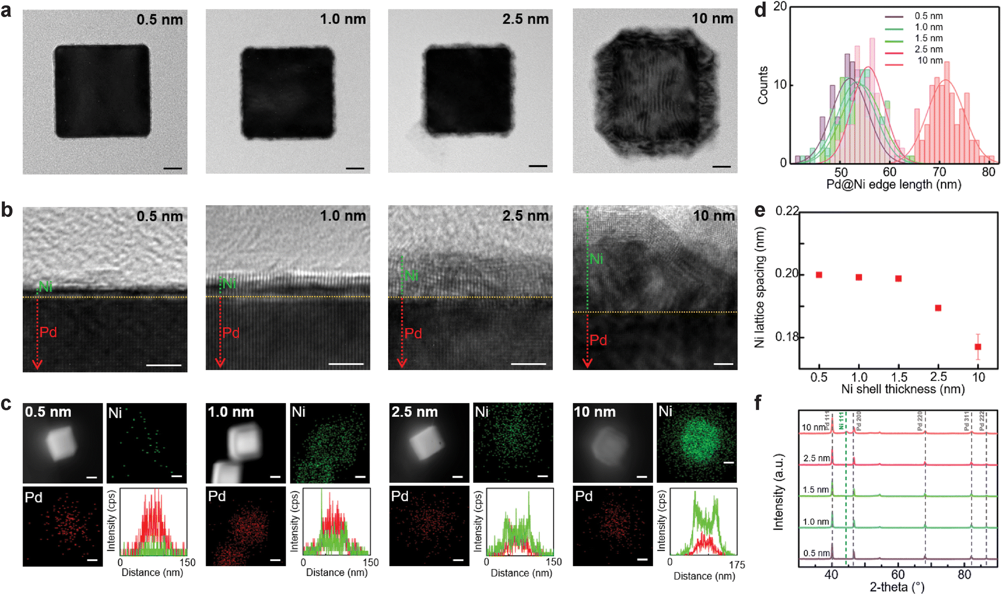 | ||
| Fig. 1 Structural analysis of Pd@Ni NCs with different Ni thickness (0.5, 1.0, 2.5, and 10 nm): TEM images (a), HRTEM images (b), elemental mapping (c), edge length distribution (d), Ni lattice spacing (e), and XRD spectra (f). In (b), the dotted green line is a guide for Ni layer, and the dotted red line is a guide for Pd layer. In (c), Ni is indicated in green, and Pd is indicated in red. Scale bars: 10 nm in (a), 2 nm in (b), and 20 nm in (c). | ||
The resulting Pd@Ni NCs were investigated by a high-resolution TEM (Fig. 1b). The interface between the Pd core and Ni shell was clearly identified by the difference in the contrast on the TEM image. The Pd@Ni NCs with thinner Ni shells appeared to have a homogeneous Ni layer, whereas Pd@Ni10 nm exhibited two distinctive layers in the Ni shell. With the increase in Ni shell thickness, the fraction of oxidised Ni atoms on the nanoparticle surface increased proportionally. Elemental mapping of the Pd@Ni by EDS (Fig. 1c) shows Pd and Ni distribution in the core–shell structures. The line scan plots confirmed the presence of Ni shell in the Pd@Ni NCs.
The lattice spacing for the Pd core was measured consistently as 0.2006 ± 0.0018 nm in Pd@Ni NCs with different Ni thicknesses, corresponding to Pd (100) planes (Fig. S6, ESI†).44 The lattice spacing for the Ni shell gradually decreased with the increasing Ni shell thickness: 0.2000 nm for Pd@Ni0.5 nm, 0.1992 ± 0.0004 nm for Pd@Ni1.0 nm, 0.1988 ± 0.0004 nm for Pd@Ni1.5 nm, 0.1894 ± 0.0005 nm for Pd@Ni2.5 nm, 0.1770 ± 0.0041 nm for Pd@Ni10 nm (Fig. 1e and Fig. S7, ESI†). That difference in the Ni lattice spacing was attributed to the tensile strain arising from the Ni lattice expansion due to the lattice mismatch between Ni and Pd.45 The XRD spectra showed no metallic Ni peaks in Pd@Ni0.5 nm, Pd@Ni1.0 nm, Pd@Ni1.5 nm, and Pd@Ni2.5 nm, whereas Pd@Ni10 nm contained a small metallic Ni peak at 44.3° (Fig. 1f). Since the amount of Ni in Pd@Ni NCs were relatively small, bulk crystallinity measurement could not be sensitive enough to reveal the crystallinity of the Ni shell layer in the Pd@Ni NCs with only several atomic layers of Ni.
Next, we investigated the effect of the Ni shell thickness on the electrocatalytic performance of the Pd@Ni NCs. First, the electrochemical behaviour of Pd@Ni NCs anodes (see ESI for details, p. S3†) was studied using CV in 1 M KOH solution (Fig. 2a). All studied Pd@Ni NCs showed the same onset potential of 1.34 V vs. RHE followed by the peak corresponding to the Ni2+ → Ni3+ transition,27 which varied from 1.4 V and 1.6 V depending on the Ni shell thickness, in the following order: Pd@Ni0.5 nm < Pd@Ni1.0 nm < Pd@Ni1.5 nm < Pd@Ni2.5 nm < Pd@Ni10 nm. The electrochemical behaviour of Pd@Ni NCs was also compared to two reference materials: Pd NCs and Ni(OH)2 xerogel (XG) prepared via epoxide sol–gel synthesis.46 The latter has been reported to have high activity towards the oxidation of N-containing molecules, such as urea and ammonia.27,47 Similar Ni oxidation onset and peak potentials were observed in the CV of Ni(OH)2 XG, while Pd NCs showed small activity in the 1.3–1.6 V range associated with the slow oxidation of Pd surface.48
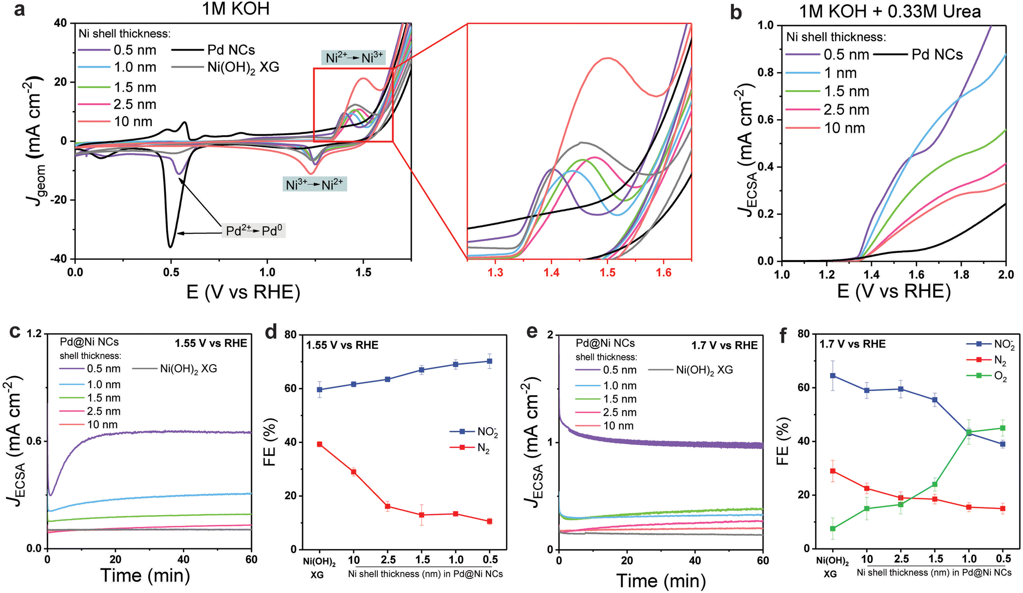 | ||
| Fig. 2 The electrochemical performance of Pd@Ni NCs. (a) CV recorded at 20 mV s−1 scan rate at Pd@Ni NCs with different shell thickness, Pd NCs and Ni(OH)2 xerogel in 1 M KOH. (b) ECSA-normalised anodic sweeps of CV recorded at 20 mV s−1 scan rate at Pd@Ni NCs with different shell thickness and Pd NCs in 1 M KOH containing 0.33 M urea. ECSA was determined based on the Ni redox peak surface area in 1 M KOH for Pd@Ni NCs and using CO stripping method for Pd NCs. (c) ECSA-normalised chronoamperometry curves (c and e) and FEs of the major products of 0.33 M urea electrolysis (d and f) in 1 M KOH performed at 1.55 V (c and d) and 1.7 V (e and f) using Pd@Ni NCs with different shell thickness or Ni(OH)2 xerogel as the anode. | ||
For all studied anodes, OER wave was observed at more positive potentials than Ni2+ → Ni3+ transition. The OER potential at 10 mA cm−2 increased in the following order: Pd NCs < Pd@Ni0.5 nm < Pd@Ni1.0 nm, Pd@Ni1.5 nm < Pd@Ni2.5 nm < Pd@Ni10 nm, Ni(OH)2 XG. This observation indicated the higher activity towards OER of Pd@Ni with higher lattice strain. The reversed CV scan showed a peak near 1.2 V associated with the Ni3+ → Ni2+ transition for all studied Pd@Ni NCs. In the case of Pd@Ni0.5 nm, an additional peak appeared at 0.5 V related to the Pd2+ → Pd0 transition, indicating the presence of exposed Pd sites in this sample. For all other samples, Pd core surface was completely covered by the Ni shell and thus no Pd oxidation features were observed in CV.
Next, we performed CV in the presence of 0.33 M urea in 1 M KOH. The urea oxidation curve appeared at the Ni2+ oxidation potentials in agreement with previous reports (Fig. 2b), while almost no activity was observed for Pd NCs, indicating that Pd is not active towards UOR at this potential range. The high UOR activity observed in Ni2+ → Ni3+ transition zone is associated with Ni3+ being the active site for urea oxidation that was demonstrated in earlier mechanistic studies.27 We note that according to the XPS analysis of anodes (Fig. S8†), the studied materials showed high density of the surface Ni3+ reactive sites, which further increased after urea electrolysis (two major peaks were noticeable in the raw data that can be attributed to Ni3+ peak at 856.6 eV and satellites at slightly higher binding energies).49 To compare the intrinsic activity of studied materials, the electrochemically active surface area (ECSA) was determined based on the Ni redox peak surface area (see ESI for details, p. S4 and Table S1†) and the J(E) plots were normalized by ECSA. We found that the intrinsic activity (determined as the potential at JECSA of 0.2 mA cm−2 near the UOR onset potential) decreased with increasing shell thickness. As confirmed by HRTEM imaging, when the lattice of Ni expands, tensile strain can lead to an upward shift of the d-band centre to Fermi level,50 facilitating the formation of a bond between the metal active site and the UOR key intermediates or urea itself. Thus, Pd@Ni0.5 nm showed the highest activity towards UOR, while Pd@Ni10 nm showed the lowest activity. We note that at more positive potentials (>1.6 V) the curve features for Pd@Ni0.5 nm NCs were similar to that for Pd NCs, suggesting the highest impact of competing OER at high applied potentials for this material.
To evaluate the influence of the surface strain on the UOR product distribution, we performed a series of potentiostatic electrolyses at two arbitrary potentials selected before and after the OER onset potential (1.55 V and 1.70 V, respectively). The gas products (N2 and O2) were analysed using in-line GC every 20 min, while the ionic UOR products (NO2−, NO3−) were analysed by IC. The results are summarised in the Fig. 2c–f.
When the reaction was performed at 1.55 V (Fig. 2c and d), the JECSA decreased with the increasing shell thickness, which was in agreement with the higher activity of materials with higher surface strain discussed above. As for the reaction selectivity, no O2 formation was observed at this potential for all Pd@Ni NCs, with N2 and nitrite being the two major products. The formation rate for both products followed an exponential trend in the case of Pd@Ni NCs with the shell thickness ≤2.5 nm while remaining constant in the case of the shell thickness >2.5 nm (Fig. S9a†). The highest FE of N2 was observed for Pd@Ni10 nm (29%), and the values decreased gradually with decreasing shell thickness to 10.5% for Pd@Ni0.5 nm. At the same time, the opposite trend was observed for the nitrite formation with the highest FE of 70% for Pd@Ni0.5 nm and the lowest FE of 59.6% for Pd@Ni10 nm anode. The ratio of nitrite to N2 decreased from 6.5 to about 2 with increasing Ni shell thickness from 0.5 nm to 10 nm, respectively (Fig. S9c†), demonstrating noticeable suppression of N2 pathway for Pd@Ni with thin shell. Interestingly, the reference Ni(OH)2 xerogel with a high availability of oxygen vacancies27 showed noticeably higher N2 selectivity (39%) compared to all Pd@Ni NCs. It has been recently shown by our group that UOR follows N2 pathway predominantly when both N centres of urea molecule bind to the two adjacent catalytic active Ni sites, which is a function of oxygen vacancies availability.27 At the same time, the formation of NOx− species proceeds via a single vacancy pathway, i.e., with only one N centre binding to the Ni site on the catalyst surface.27 The observed experimental trend demonstrated that the thinner the Ni shell is, the more N2 pathway is suppressed. Since the oxygen adsorption strength increases with increasing tensile strain,51 one can expect a lower availability of oxygen vacancies in Pd@Ni NCs with a thin shell compared to the very disordered Ni(OH)2 xerogel material, resulting in the suppression of N2 pathway (Fig. 3).
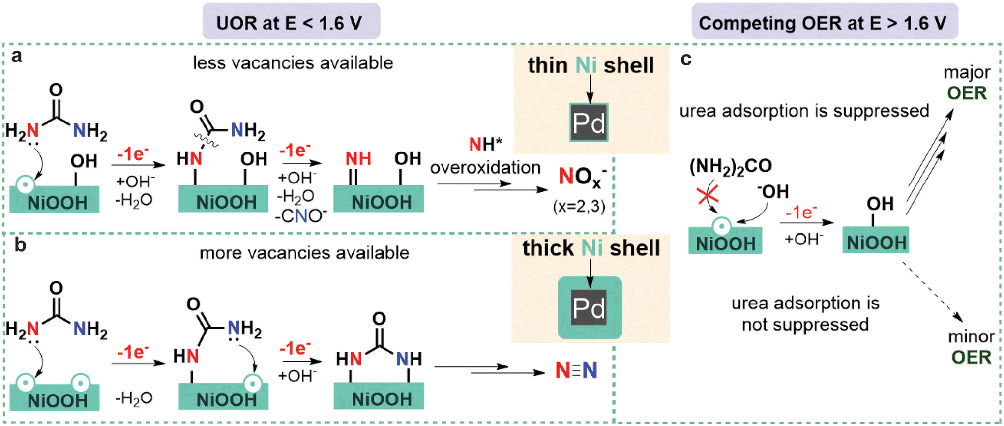 | ||
| Fig. 3 The effect of the tensile strain on the UOR mechanistic pathways and competing OER. (a and b) A schematic illustration of the proposed pathways for UOR to NOx− products (a) N2 (b) on the NiOOH surface of Pd@Ni NCs with thin shell (a) and thick shell (b) at E < 1.6 V vs. RHE. (c) A schematic illustration of the competition between UOR and OER on the NiOOH surface of Pd@Ni NCs with thin shell and thick shell at E > 1.6 V vs. RHE. | ||
At a more positive potential (1.7 V), UOR proceeded with the formation of O2 in addition to N2 and nitrite (Fig. 2e and f). Similar to the results obtained for 1.55 V, the rate of O2, N2, and nitrate formation followed an exponential trend for Pd@Ni NCs with the shell thickness ≤2.5 nm and remained almost constant for the shell thickness >2.5 nm (Fig. S9b†). A significant increase in FE of O2 from 15% to 45% was observed with decreasing shell thickness. In agreement with the CV data, no UOR activity was observed for bare Pd NCs even at higher potentials (1.8 V) with O2 being the only reaction product. We note that in the case of Pd@Ni0.5 nm being the only anode with partially exposed Pd surface some O2 can be produced on Pd sites due to their high affinity to OER intermediates. Although it is beyond the scope of this work, the performance of Ni–Pd alloys in UOR can be of interest for further studies. For instance, it has been shown that the introduction of noble metals to the surface of Ni and Cu oxides can tune the selectivity in electrochemical oxidation of ammonia and similar effect should be explored in UOR.52
The ratio of O2 to UOR products for the electrolysis at 1.7 V exponentially increased with decreasing Ni shell thickness, reaching 0.8 for the 0.5 nm shell (Fig. S9d†). The N2 selectivity trend was the same as for the experiments at 1.55 V, with the highest N2 FE (22.5%) observed for Pd@Ni10 nm anode and the lowest N2 FE (15%) observed for Pd@Ni0.5 nm anode. Ni(OH)2 xerogel material showed a higher FE of N2 than all Pd@Ni NCs, which again can be attributed to a higher availability of oxygen vacancies in this material. The highest FE of nitrite was observed for Pd@Ni10 nm (59%), and the values decreased gradually with decreasing shell thickness to 39% for Pd@Ni0.5 nm. The latter observation can be explained by the competition of OER and urea overoxidation pathways, since similar intermediates should be involved in both reactions. The observed significant contribution of OER under these conditions correlates with higher adsorption energies of OER intermediates compared to urea at high positive potentials, which was recently revealed by DFT calculations.53 The tensile strain in this case additionally stabilises OER intermediates, making competing OER more pronounced (Fig. 3).
Finally, to estimate the stability of synthesized materials during UOR and its effect on the reaction outcome, we carried out long-term electrolysis (4 hours) at 1.7 V for Pd@Ni1 nm and Pd@Ni10 nm. A small decrease of 5% in current density was observed for the electrolysis with Pd@Ni1 nm anode. The FE of O2 remained almost constant in the course of electrolysis, while FE of N2 increased from 20% in the beginning of electrolysis to 32% at the end (Fig. S10a†). For Pd@Ni10 nm anode 35% increase in current density was observed after 4 hours of electrolysis. Interestingly, the FE of N2 remained nearly constant, while a very small decrease in O2 FE was observed (Fig. S10b†). The results of these experiments suggest that the surface evolution is happening during UOR, gradually changing the catalyst selectivity. Further studies supported by DFT calculations are required to better understand how the catalyst morphology changes affect the reaction kinetics and product distribution, which is beyond the scope of this work.
In conclusion, we developed a strategy for the colloidal synthesis of epitaxial Pd@Ni NCs with adjustable Ni shell thickness and resulting lattice expansion by the tensile strain, which enabled fine-tuning of their catalytic properties. Specifically, we showed that the synthesised nanoparticles exhibit a high dependence of the product distribution in UOR on the surface strain and the applied potential. At low potentials (E < 1.6 V), UOR at Pd@Ni NCs proceeds without competing OER, yielding N2 and nitrite as major products. The FE of N2 decreases significantly with decreasing shell thickness (from 29% to 10.5% for Pd@Ni NCs with 10 nm and 0.5 nm Ni shell, respectively), while nitrite FE increases proportionally. The observed trend points at a lower availability of oxygen vacancies in Pd@Ni NCs with thin shell, which leads to the suppression of N2 pathway. At more positive potentials (E > 1.6 V), a noticeable contribution of competing OER was observed, and the FE of O2 increased dramatically with decreasing shell thickness (up to 45% for Pd@Ni NCs with 0.5 Ni shell). The significant contribution of OER is associated with the higher adsorption energies of OER intermediates compared to urea at high positive potentials. Thus, we demonstrated that the specific lattice strain in Pd@Ni NCs plays a significant role in the UOR selectivity, enabling the dominance of overoxidation pathway over nitrogen evolution. The results are foundational for further developments of active and selective UOR catalysts via strain effect modulation. In particular, based on the reported insights, future work should be devoted to studying the effect of other core materials in Ni-catalysed UOR to tune the surface strain type and value to favour the more desirable nitrogen evolution pathway.
Author contributions
Conceptualisation, A. K.; validation, J. K., X. M.; formal analysis, J. K., X. M., C. B.; writing-original draft preparation, J. K., J. J. M., J. K., A. K.; writing-review and editing, J. K., X. M., J. J. M., J. K., A. K.; visualisation, J. K., J. J. M., X. M.; supervision, J. K., A. K.; project administration, J. K., A. K.; funding acquisition, J. K., A. K.Conflicts of interest
There are no conflicts to declare.Acknowledgements
A. K. acknowledges the financial support from the University of Waterloo, Waterloo Institute for Nanotechnology, Natural Sciences and Engineering Council of Canada (DG and RTI Funds), Canada Foundation for Innovation, and Ontario Research Fund. J. K. acknowledges the financial support from Korea Institute for Advancement of Technology (P0017310) and National Research Foundation of Korea (2020R1C1C1007568 and 2022R1A4A1022252).References
- R. Lan, S. Tao and J. T. S. Irvine, Energy Environ. Sci., 2010, 3, 438–441 RSC.
- R. K. Singh, K. Rajavelu, M. Montag and A. Schechter, Energy Technol., 2021, 9, 2100017 CrossRef CAS.
- H. Meessen, Urea. In Ullmann's Encycl. Ind. Chem, Wiley-VCH, Weinheim, 2000 Search PubMed.
- B. M. Comer, P. Fuentes, C. O. Dimkpa, Y.-H. Liu, C. A. Fernandez, P. Arora, M. Realff, U. Singh, M. C. Hatzell and A. J. Medford, Joule, 2019, 3, 1578–1605 CrossRef CAS.
- E. Urbańczyk, M. Sowa and W. Simka, J. Appl. Electrochem., 2016, 46, 1011–1102 CrossRef.
- L. E. Scherger, V. Zanello and C. Lexow, Bull. Environ. Contam. Toxicol., 2021, 107, 565–573 CrossRef CAS PubMed.
- W. H. R. Shaw and J. J. Bordeaux, J. Am. Chem. Soc., 1955, 77, 4729–4733 CrossRef CAS.
- X. V. Medvedeva, J. J. Medvedev, S. W. Tatarchuk, R. M. Choueiri and A. Klinkova, Green Chem., 2020, 22, 4456–4462 RSC.
- X. Sun and R. Ding, Catal. Sci. Technol., 2020, 10, 1567–1581 RSC.
- V. Climent, A. Rodes, J. M. Orts, A. Aldaz and J. M. Feliu, J. Electroanal. Chem., 1999, 461, 65–75 CrossRef CAS.
- D. Suárez, N. Díaz and K. M. Merz, J. Am. Chem. Soc., 2003, 125, 15324–15337 CrossRef PubMed.
- G. Estiu and K. M. Merz, J. Am. Chem. Soc., 2004, 126, 11832–11842 CrossRef CAS PubMed.
- J. Li, S. Sun, Y. Yang, Y. Dai, B. Zhang and L. Feng, Chem. Commun., 2022, 58, 9552–9555 RSC.
- S. Wang, X. Yang, Z. Liu, D. Yang and L. Feng, Nanoscale, 2020, 12, 10827–10833 RSC.
- S. Wang, L. Zhao, J. Li, X. Tian, X. Wu and L. Feng, J. Energy Chem., 2022, 66, 483–492 CrossRef CAS.
- S. Wang, J. Zhu, X. Wu and L. Feng, Chin. Chem. Lett., 2022, 33, 1105–1109 CrossRef CAS.
- B. Zhu, Z. Liang and R. Zou, Small, 2020, 16, 1906133 CrossRef CAS PubMed.
- K. Ye, G. Wang, D. Cao and G. Wang, Top. Curr. Chem., 2018, 376, 42 CrossRef PubMed.
- W. Xu, Z. Wu and S. Tao, Energy Technol., 2016, 4, 1329–1337 CrossRef CAS.
- Y. Wang, C. Wang, H. Shang, M. Yuan, Z. Wu, J. Li and Y. Du, J. Colloid Interface Sci., 2022, 605, 779–789 CrossRef CAS PubMed.
- X. Li, X. Cui and L. Jiang, Catal. Commun., 2022, 162, 106390 CrossRef CAS.
- V. T. Veettil, A. U. Vijayakumar, A. Ashdot and D. Zitoun, ACS Appl. Energy Mater., 2022, 5, 1397–1402 CrossRef CAS.
- Q. Zhao, C. Meng, D. Kong, W. Wang, H. Hu, X. Chen, Y. Han, X. Chen, Y. Zhou, M. Lin and M. Wu, ACS Sustainable Chem. Eng., 2021, 9, 15582–15590 CrossRef CAS.
- Q. He, Y. Wan, H. Jiang, Z. Pan, C. Wu, M. Wang, X. Wu, B. Ye, P. M. Ajayan and L. Song, ACS Energy Lett., 2018, 3, 1373–1380 CrossRef CAS.
- J. Li, J. Li, T. Liu, L. Chen, Y. Li, H. Wang, X. Chen, M. Gong, Z.-P. Liu and X. Yang, Angew. Chem., Int. Ed., 2021, 60, 26656–26662 CrossRef CAS PubMed.
- L. Zhang, L. Wang, H. Lin, Y. Liu, J. Ye, Y. Wen, A. Chen, L. Wang, F. Ni, Z. Zhou, S. Sun, Y. Li, B. Zhang and H. Peng, Angew. Chem., Int. Ed., 2019, 58, 16820–16825 CrossRef CAS PubMed.
- S. W. Tatarchuk, J. J. Medvedev, F. Li, Y. Tobolovskaya and A. Klinkova, Angew. Chem., Int. Ed., 2022, 61, e202209839, DOI:10.1002/anie.202209839.
- L. Huang, X. Zhang, Y. Han, Q. Wang, Y. Fang and S. Dong, Chem. Mater., 2017, 29, 4557–4456 CrossRef CAS.
- L. Huang, X. Zhang, Q. Wang, Y. Han, Y. Fang and S. Dong, J. Am. Chem. Soc., 2018, 140, 1142–1147 CrossRef CAS PubMed.
- X. Jiang, G. Fu, X. Wu, Y. Liu, M. Zhang, D. Sun, L. Xu and Y. Tang, Nano Res., 2018, 11, 499–510 CrossRef CAS.
- L. Huang, J. Zou, J.-Y. Ye, Z.-Y. Zhou, Z. Lin, X. Kang, P. K. Jain and S. Chen, Angew. Chem., Int. Ed., 2019, 58, 8794–8798 CrossRef CAS PubMed.
- M. Baumung, F. Schönewald, T. Erichsen, C. A. Volkert and M. Risch, Sustainable Energy Fuels, 2019, 3, 2218–2226 RSC.
- B. P. Williams, M. Yaguchi, W.-S. Lo, C.-R. Kao, L. K. Lamontagne, B. T. Sneed, C. N. Brodsky, L.-Y. Chou, C.-H. Kuo and C.-K. Tsung, Nanoscale, 2020, 12, 8687–8692 RSC.
- J. L. Santos, C. Megías-Sayago, S. Ivanova, M.Á. Centeno and J. A. Odriozola, Chem. Eng. J., 2021, 420, 127641 CrossRef CAS.
- M. Liu, M. Xie, Y. Jiang, Z. Liu, Y. Lu, S. Zhang, Z. Zhang, X. Wang, K. Liu and Q. Zhang, et al. , J. Mater. Chem. A, 2021, 9, 15373–15380 RSC.
- Z. Xia and S. Guo, Chem. Soc. Rev., 2019, 48, 3265–3278 RSC.
- X. Yang, Y. Wang, X. Tong and N. Yang, Adv. Energy Mater., 2022, 12, 2102261 CrossRef CAS.
- C. Li, S. Yan and J. Fang, Small, 2021, 17, 2102244 CrossRef CAS PubMed.
- T. He, W. Wang, F. Shi, X. Yang, X. Li, J. Wu, Y. Yin and M. Jin, Nature, 2021, 598, 76–81 CrossRef CAS PubMed.
- A. Klinkova, E. M. Larin, E. Prince, E. H. Sargent and E. Kumacheva, Chem. Mater., 2016, 28, 3196–3202 CrossRef CAS.
- B. T. Sneed, A. P. Young, D. Jalalpoor, M. C. Golden, S. Mao, Y. Jiang, Y. Wang and C.-K. Tsung, ACS Nano, 2014, 8, 7239–7250 CrossRef CAS PubMed.
- M. Grzelczak, J. Perez-Juste, B. Rodriguez-Gonzalez, M. Spasova, I. Barsukov, M. Farle and L. M. Liz-Marzan, Chem. Mater., 2008, 20, 5399–5405 CrossRef CAS.
- M. Jin, H. Zhang, J. Wang, X. Zhong, N. Lu, Z. Li, Z. Xie, M. J. Kim and Y. Xia, ACS Nano, 2012, 6, 2566–2573 CrossRef CAS PubMed.
- B. T. Sneed, A. P. Young, D. Jalalpoor, M. C. Golden, S. Mao, Y. Jiang, Y. Wang and C.-K. Tsung, ACS Nano, 2014, 8, 7239–7250 CrossRef CAS PubMed.
- Z. Zheng, Y. H. Ng, D.-W. Wang and R. Amal, Adv. Mater., 2016, 28, 9949–9955 CrossRef CAS PubMed.
- S. W. Tatarchuk, R. M. Choueiri, X. V. Medvedeva, L. D. Chen and A. Klinkova, Chemosphere, 2021, 279, 130550 CrossRef CAS PubMed.
- J. J. Medvedev, Y. Tobolovskaya, X. V. Medvedeva, S. W. Tatarchuk, F. Li and A. Klinkova, Green Chem., 2022, 24, 1578–1589 RSC.
- L. An, Y. Chen, J. Shi, J. Cao, B. Liu and J. Yang, Front. Chem., 2018, 6, 596 CrossRef CAS PubMed.
- P. Dubey, N. Kaurav, R. S. Devan, G. S. Okram and Y. K. Kuo, RSC Adv., 2018, 8, 5882–5890 RSC.
- E. M. Dietze and H. Grönbeck, ChemPhysChem, 2020, 21, 2407–2410 CrossRef CAS PubMed.
- N. Ma, N. Li, T. Wang, X. Ma and J. Fan, J. Mater. Chem. A, 2022, 10, 1390–1401 RSC.
- S. S. P. Rahardjo and Y.-J. Shin, ACS Sustainable Chem. Eng., 2022, 10, 5043–5054 CrossRef.
- R. Lin, L. Kang, T. Zhao, J. Feng, V. Celorrio, G. Zhang, G. Cibin, A. Kucernak, D. J. L. Brett, F. Corà, I. P. Parkin and G. He, Energy Environ. Sci., 2022, 15, 2386–2396 RSC.
Footnote |
| † Electronic supplementary information (ESI) available: Experimental details, materials characterisation, electrochemical measurement, TEM image and UV-visible spectrum of Pd NCs, TEM and SEM images of Pd@Ni NCs with different synthesis conditions, Ni lattice spacing measurement, XPS spectra, and ECSA values. See DOI: https://doi.org/10.1039/d2nr05950a |
| This journal is © The Royal Society of Chemistry 2023 |