Heterostructural TiO2/Ti3C2 MXene aerogel composite for photocatalytic degradation of palm oil mill effluent
Received
26th May 2022
, Accepted 18th August 2022
First published on 19th August 2022
Abstract
The design of effective POME treatment is crucial to mitigate the waste production of the palm oil industry. Against this backdrop, the use of TiO2 based photocatalytic degradation technology for POME degradation is of viable interest due to the possibility of total organic substrate oxidation. Herein, a heterostructural aerogel composite comprising {001}-TiO2 and Ti3C2 MXene aerogel was synthesised to investigate its POME photodegradation efficiency. POME degradation was done under black light irradiation and without external oxygen bubbling to mimic the photodegradation process under natural ponding conditions. Characterisation results showed an increase in the surface roughness and porosity of the Ti3C2 aerogel structure which enhanced its contact with TiO2 leading to the formation of interfacial heterojunctions. With the synergy of Schottky-junction hole trapping and exposed active {001} TiO2 facets arising from the interfacial heterojunction, the composite was reported to have a POME degradation efficiency of 98.3% over 24 h which is higher as compared with that of the Ti3C2 aerogel (73.7%) and TiO2 (58.9%). The improved electron–hole separation and active facet exposure of the TiO2/Ti3C2 heterostructure indicate the potential applications of two-dimensional transition metal carbides for waste treatments via photocatalysis.
Environmental significance
Palm oil mill effluent (POME) is one of the major industrial pollutants of the palm oil industry during crude palm oil production. With the current biological POME treatment technology, it is still rather challenging to discharge such treated effluent that could meet the standards of the Environmental Quality Act 1974. Thus, the application of better POME treatment such as organic substrate oxidation via photocatalysis is necessary in accordance with United Nations' Sustainable Development Goal 6 (about clean water and sanitation). This paper through the synthesis and the application of a TiO2 based MXene photocatalyst attempts to understand the role of MXenes in improving the photocatalytic activity of TiO2 for POME degradation.
|
1 Introduction
The palm oil industry has contributed significantly to the Malaysian economy and has served as the backbone of the Malaysian agriculture sector throughout the years. In this industry, palm oil functions as the raw material for the production of edible crude palm oil (CPO) that can be further processed into cooking oil, cosmetics, hair care products, etc.1 Palm oil processing often involves numerous processes such as pressing, milling, sterilisation, extraction and digestion where most of the stages will require excess amounts of water. During CPO production, only 10% of useful oil can be extracted from the fresh fruit bunches (FFB) and the remaining fractions will be discarded as wastes such as empty fruit bunches (EFB), shells, fibres and palm oil mill effluent (POME).
Among these wastes, POME is the largest waste generated during CPO production in which 2.5 MT of POME will be produced for 1 MT of CPO yield.2,3 POME is a high production liquid waste from the palm oil industry. It is viscous, brownish and has high BOD (10![[thin space (1/6-em)]](https://www.rsc.org/images/entities/char_2009.gif) 250–43
250–43![[thin space (1/6-em)]](https://www.rsc.org/images/entities/char_2009.gif) 750) and COD (15
750) and COD (15![[thin space (1/6-em)]](https://www.rsc.org/images/entities/char_2009.gif) 000–100
000–100![[thin space (1/6-em)]](https://www.rsc.org/images/entities/char_2009.gif) 000) which makes it a much more significant water pollutant than municipal sewage.4 Additionally, POME is rich in palm oil based organic compounds such as carotenes, carboxylic acids, pectin, lignin and phenolics which are harmful to the ecological environment.3,5–7 Furthermore, POME can be difficult to handle, as the production of POME often occurs on a massive scale and the conventional POME treatment method is ineffective where a long duration is needed for POME degradation.8,9
000) which makes it a much more significant water pollutant than municipal sewage.4 Additionally, POME is rich in palm oil based organic compounds such as carotenes, carboxylic acids, pectin, lignin and phenolics which are harmful to the ecological environment.3,5–7 Furthermore, POME can be difficult to handle, as the production of POME often occurs on a massive scale and the conventional POME treatment method is ineffective where a long duration is needed for POME degradation.8,9
In Malaysia, POME has been treated conventionally with a biological treatment system, which is also known as open ponding treatment.10 Despite having such a POME treatment system, POME has still been identified as one of the major industrial pollutants in Malaysia. Hence, environmental regulations regarding POME waste management practices in the palm oil mill industry have been implemented and enforced.11 To date, there have been several regulatory and legislative frameworks that have detailed the threshold for the discharge of POME, such as the Environmental Quality Act 1974 and Environmental Quality (Prescribed Premises) (Crude Palm Oil) (Amendment) Regulations 1977. It is noteworthy that there should be a strict compliance with these legislation frameworks in order to ensure environmental sustainability and to achieve United Nations' Sustainable Development Goal 6 that focuses on clean water and sanitation.3
Although palm oil is a sustainable product, POME can have an adverse impact on the environment if it is not treated properly prior to discharge. For instance, POME has a high content of N, K, and P elements and traces of Mg and Ca which will promote eutrophication and lead to the occurrence of oxygen depletion in water streams. This phenomenon can subsequently lead to an imbalance in the aquatic ecology. Additionally, direct discharge of POME onto the soil can lead to high soil degradation, owing to the increment in heavy metal contamination which can be a hazard to both humans and the ecosystem, through ground water contamination and direct ingestion.7 Thus, a proper design of an effective POME treatment system is required to minimise the production of palm oil industrial waste. As an open ponding system requires long processing time and large pond area, and produces significant amounts of solid wastes in the form of sludge, recent studies in this area have been focusing on the use of a TiO2 based photocatalytic degradation system which offers higher POME treatment efficiency.12,13
In photocatalysis, TiO2 is a very well established semiconductor based photocatalyst for treating organic wastes due to its low cost, nontoxicity and high chemical stability.13 Activation of TiO2 photocatalysis is commonly achieved via ultraviolet (UV) irradiation which excites TiO2 electrons in the valence band to the conduction band, leading to creation of electron–hole pairs.14 The free electrons will reduce oxygen molecules into superoxide radicals while the holes will oxidise water molecules into hydroxyl radicals and hydrogen ions. Both of these radicals are vital for the degradation of organic wastes. However, the use of the TiO2 photocatalyst is limited by its inability to undergo photocatalytic activation in the visible light range and its low charge separation efficiency.15,16 TiO2 has a bandgap of 3.2 eV which requires ultraviolet light absorption at a wavelength of 387 nm for its photocatalysis. The UV absorption requirement indicates that TiO2 cannot undergo facile activation under solar irradiation as the sunlight reaching the surface of the Earth is primarily composed of infrared radiation (49.4%) and visible light (42.3%) instead of UV light (8%).17 This will certainly retard the efficiency of solar-irradiated TiO2-photocatalysed processes in treating organic wastes.
TiO2 is also known to have a large number of electrons and holes that will speed up the recombination rate of electron–hole pairs and reduce the lifetime of photogenerated charge carriers.18 All of this leads to low charge separation efficiency in TiO2 where the charge carriers tend to recombine prior to reaching the surface for photocatalytic processes. Two strategies are commonly applied to address these issues: (i) facet engineering of the TiO2 nanocrystal, and (ii) electronic coupling of TiO2 with a cocatalyst material to form a heterojunction TiO2 photocatalyst.19 TiO2 has non-equivalent surfaces with different catalytic abilities. For instance, the {101} plane serves as the reduction site and the {001} plane serves as the oxidation site. This offers the possibility of modifying charge separation and trapping sites via controlling the facet distribution during TiO2 nanocrystal synthesis. Nevertheless, a facet-engineered TiO2 nanocrystal is still contingent on the intrinsic properties of its facets, causing the enhancement of photocatalytic activity of facet-engineered TiO2 to be rather limited. Therefore, the study of heterojunction TiO2 photocatalysts is often focused on due to the unlimited enhancement possibility from the cocatalyst. The cocatalyst is a secondary material, preferably a good electronic conductor, that is used to improve charge separation efficiency and/or reduce the bandgap of TiO2 such that its photocatalysis can be improved or activated in the visible light range. There are numerous secondary material groups that are being studied for the synthesis of TiO2 composite photocatalysts, such as elemental metals, metal oxides, metal sulphides, bi-metals and graphene.19–24
Recently, a two-dimensional (2D) material, MXene, has emerged as a promising material for photocatalytic reactions as it exhibits excellent catalytic, electronic and optoelectronic properties.25,26 In addition, the 2D structures of MXene minimise the migration distance between charge carriers and the reaction interface, which inhibits the possibility of charge carrier recombination and further improves the photocatalytic performance. MXenes are the latest addition to the 2D materials family, with the general formula of M(n+1)XnTx, where M refers to an early transition metal, X represents a carbon and/or nitrogen atom and Tx represents surface terminations.27 They have emerged as a trending material, attracting research interest in photocatalytic reactions due to several characteristics such as large specific surface area with abundant functional groups, prominent metallic conductivity which ensures efficient separation of photogenerated electrons and holes, and high reactivity owing to the exposed terminal metal sites.28
Several studies have explored the use of the TiO2/Ti3C2 heterostructure for H2 production,29,30 water splitting,31 and dye and drug degradation32–34 where a significant improvement in photocatalytic activity was reported due to the formation of heterojunctions. As there is no current study on the use of TiO2/Ti3C2 for POME degradation to the best of the authors' knowledge, the incorporation of Ti3C2 MXene into the existing TiO2 photocatalyst for POME degradation is an uncharted area of research where its findings are expected to improve the current photocatalytic technology for POME degradation. Thus, this work presents the synthesis of a TiO2/Ti3C2 MXene aerogel composite and its application in photocatalytic degradation of POME. Formation of heterojunctions within TiO2/Ti3C2 interfaces was also studied to determine the effects on the photocatalytic degradation efficiency of TiO2 based photocatalysts. The mechanisms and possible pathways of photocatalytic degradation for POME were also investigated.
2 Materials and methods
2.1 Chemicals
The palm oil mill effluent (POME) sample used in this study was obtained from the final discharge point of Gomali Palm Oil Mill, IOI Group, located in Johor, Malaysia. The POME sample was stored in a polystyrene box in order to avoid light exposure during transportation. Then, the POME sample was filtered to remove suspended solids and stored at 4 °C for preservation. Titanium aluminium carbide (Ti3AlC2, MAX phase 312, ≤100 μm particle size, ≥90% purity) and titanium(IV) oxide (TiO2, anatase, particle size 20 nm, >99% purity) powders were purchased from Chemsoln Sdn Bhd. Hydrochloric acid (HCl, 37%, A.R.) was purchased from R&M Chemicals. Lithium fluoride (LiF, particle size −300 mesh) powder was purchased from Sigma Aldrich.
2.2 Synthesis of Ti3C2 MXene
Ti3C2 MXene sheets were prepared by removing Al from the MAX phase via the in situ HF etching technique.35 To in situ prepare the HF etchant, a 1.6 g portion of LiF powder was added into 20 mL of 9.0 M HCl in a Teflon container. 1.0 g of Ti3AlC2 powder was gradually added into the composite etchant. Subsequently, the reaction medium was kept at 35 °C for 36 h under magnetic stirring. The resultant solution was then repeatedly centrifuged at 3500 rpm for 10 minutes per cycle and washed in 200 mL of deionised water until the pH reached 7. Finally, a stable black supernatant of Ti3C2Tx was obtained and probe sonicated for delamination at ambient temperature for 1 h. The mixture was centrifuged at 1500 rpm for 20 minutes to remove the residual Ti3AlC2. Lastly, Ti3C2 MXene sheets were freeze-dried for 48 h.
2.3 Synthesis of Ti3C2 MXene aerogel
A 30 mg portion of freeze-dried Ti3C2 MXene was dispersed in 10 mL of deionised water and stirred magnetically for 30 minutes to form MXene colloidal solution. The MXene colloidal solution was then sealed in a Teflon container and heated for 6 h at 95 °C. The as-formed Ti3C2 hydrogel was immersed in deionised water and washed several times to remove residuals and balance the pH of the hydrogel. Finally, Ti3C2 MXene aerogel was obtained by freeze drying the Ti3C2 hydrogel at −50 °C for 96 h.
2.4 Synthesis of TiO2/Ti3C2 MXene composite aerogel
A 100 mg portion of anatase TiO2 powder was dispersed in 100 mL of deionised water. Subsequently, the mixture was stirred to obtain a homogeneous fluid and sonicated for an hour. Then, the TiO2 suspension was mixed with 30 mg of freeze-dried MXene and stirred for 30 minutes to form a stable TiO2/Ti3C2 mixture with 77 wt% TiO2 loading. The mixture was transferred into a Teflon container for hydrothermal treatment at 120 °C for 5 h to obtain the composite hydrogel. Then, the composite hydrogel was freeze-dried at −50 °C for 96 h to obtain TiO2/Ti3C2 MXene composite aerogel.
2.5 Photocatalytic degradation test
The photocatalytic activities of the samples were examined by conducting photodegradation of POME under irradiation with UV-visible light. For each photocatalytic setup, 34 mg of photocatalyst (TiO2, Ti3C2 aerogel and TiO2/Ti3C2 composite aerogel) was added into 20 mL of filtered POME solution. The mixture was stirred continuously at 700 rpm for 1 h in the dark to establish adsorption–desorption equilibrium. Then the mixture under continuous stirring was exposed to a 100 W black light lamp for the photocatalytic test. The black light lamp is a SrB4O7![[thin space (1/6-em)]](https://www.rsc.org/images/entities/char_2009.gif) :
:![[thin space (1/6-em)]](https://www.rsc.org/images/entities/char_2009.gif) Eu phosphor mixture with spectral bandwidth at 370 ± 20 nm and 404 nm to simulate the UV-visible light irradiation from sunlight. Two mL solution was extracted from the reaction system every 4 hours and centrifuged to remove the photocatalyst. The aliquot was then analysed using gas chromatography-mass spectrometry (GC-MS) analysis. As the POME solution undergoes photocatalytic degradation, it is expected to produce CO2 and water with a gradual decrease in POME solution via organic substrate oxidation with the following empirical equation:36
Eu phosphor mixture with spectral bandwidth at 370 ± 20 nm and 404 nm to simulate the UV-visible light irradiation from sunlight. Two mL solution was extracted from the reaction system every 4 hours and centrifuged to remove the photocatalyst. The aliquot was then analysed using gas chromatography-mass spectrometry (GC-MS) analysis. As the POME solution undergoes photocatalytic degradation, it is expected to produce CO2 and water with a gradual decrease in POME solution via organic substrate oxidation with the following empirical equation:36| |  | (1) |
where x, y and z are the weighted averages of C, H and O contents of organic compounds in POME solution. Thus, the photodegradation percentage of POME can be determined by measuring the amount of CO2 liberated at a particular interval of time:| |  | (2) |
where m0 is the initial mass of POME solution, Vt is the cumulative volume of CO2 liberated after time t, Vm is the molar volume of CO2 at room temperature and pressure and Mr,POME is the weighted average molar mass of POME solution.
The reusability and the stability of the TiO2/Ti3C2 composite aerogel were examined by subjecting it to five cyclical degradation runs with each run being done under identical conditions. Prior to the usage for the next degradation run, the spent catalyst was washed and dried at room temperature. Radical scavenging studies were also done to identify the reactive oxygen species and their relative importance for POME degradation. Ammonium oxalate (AO), isopropyl alcohol (IPA), benzoquinone (BQ) and Fe(II)–ethylenediamine tetraacetic acid (Fe(II)–EDTA) were used as trapping agents for h+, ·OH, ·O−2 and H2O2 respectively. The scavenging experiments were done under the same degradation conditions but with the addition of the respective trapping agents (1 mL, 1 mM).
2.6 Material characterisation
Structures of the Ti3AlC2, Ti3C2, Ti3C2 aerogel and TiO2/Ti3C2 composite samples were examined using X-ray diffraction analysis (XRD, Shimadzu XRD 6000, Japan) at 40 kV and 40 mA using Cu Kα radiation within the 2θ range of 5–80°. Nitrogen adsorption–desorption isotherms were obtained using a Micromeritics ASAP 2020 nitrogen adsorption analyser. Brunauer–Emmett–Teller (BET) specific surface areas (SBET) of the samples were obtained through a multipoint BET method using adsorption data in the relative pressure range of 0.05 to 0.30. Pore size distributions of the samples were determined via the Barrett–Joyner–Halenda (BJH) method. Pore volumes and average pore sizes of the samples were calculated at a relative pressure of 0.995.
The surface morphology and microstructures of the Ti3C2, Ti3C2 aerogel and TiO2/Ti3C2 composite samples were characterised by field emission scanning electron microscopy (FESEM, JEOL JSM-7600F) at an accelerating voltage of 5 kV. The morphology of the catalyst structures was also examined using transmission electron microscopy (TEM, TEM LEO 912 Omega equipment). Elemental mapping was done via energy dispersive X-ray (EDX) analysis along with FESEM analysis. POME samples were characterised using GC-MS analysis for organic compound identification and quantification. A single packed bed GC column (RTX5MS, 30 m × 0.25 mm ID, 0.25 μm thickness, fused silica) was used to transfer the POME samples to a Shimadzu GCMS-QP2010 SE. The operating temperature of the GC oven was set at 573 K. Temperatures of the MS detector and GC-MS injector port were set at 523 K. Split injection mode with a split ratio of 1![[thin space (1/6-em)]](https://www.rsc.org/images/entities/char_2009.gif) :
:![[thin space (1/6-em)]](https://www.rsc.org/images/entities/char_2009.gif) 50 was used. The GC column temperature was raised from 323 K to 473 K at 8 K min−1 and subsequently to 573 K at 10 K min−1. Organic compounds in POME samples were then identified using the NIST mass spectral library.
50 was used. The GC column temperature was raised from 323 K to 473 K at 8 K min−1 and subsequently to 573 K at 10 K min−1. Organic compounds in POME samples were then identified using the NIST mass spectral library.
2.7 Material simulation
Density functional theory (DFT) simulation was conducted to calculate the energy levels of TiO2 and Ti3C2 using the Cambridge Sequential Total Energy Package (CASTEP) module of Materials Studio software. Geometric structures of the compounds were optimised using the Perdew–Burke–Ernzerhof (PBE) version of the generalised gradient approximation while electronic structures were calculated using the HSE06 hybrid functional. For the electronic structure iteration, convergence standards of 1.0 × 10⁻⁵ eV per atom for energy, 0.001 Å for max displacement, 0.005 GPa for maximum pressure and 0.03 eV Å−1 for maximum force were used. van der Waals interactions and interactions between the valence electrons and ionic core were simulated using the Grimme empirical correlation and norm-conserving pseudopotentials respectively.
3 Results and discussion
3.1 Characterisation of Ti3C2, Ti3C2 aerogel and the TiO2/Ti3C2 aerogel composite
The XRD patterns of Ti3AlC2 MAX and Ti3C2 MXene are in agreement with the XRD results obtained from previous studies.32,37–39 The distinct (002) diffraction peak of Ti3C2 MXene was observed at 2θ = 8.98° which was shifted from 2θ = 9.48° in Ti3AlC2 MAX. The peak downshift indicates a slight increase in interlayer spacing of MXene due to in situ HF etching. The removal of Al layers from the MAX phase during in situ HF etching also resulted in the disappearance of the prominent XRD peaks of the MAX phase such as the (004), (100), (102), (104), (105), (109) and (1012) peaks at 2θ = 19.44°, 34.01°, 36.75°, 38.77°, 42.34°, 56.28°, and 70.42° respectively. The MAX phase was noted to have higher crystallinity than 2D Ti3C2 MXene nanosheets due to its sharper and narrower XRD peaks.
The formed Ti3C2 MXene aerogel had no change in its crystallinity and structural phases as indicated by the identical XRD patterns of both 2D Ti3C2 MXene nanosheets and Ti3C2 MXene aerogel in Fig. 1. The aerogel consists of an extremely low density yet large surface area with porous structures from a 3D porous solid network. It is generally a centimetre sized monolith structure with nanoscale features, which displays a combination of macro- and microscale features that are advantageous for environmental remediation and solar energy conversion.40–42 The MXene is made into an aerogel form in this study as a monolith-structured aerogel is generally more convenient in its utilisation. It avoids intricate operations needed for powdered nanoparticles by being able to separate easily from water without secondary pollution after the treatment usage.43 Development of heterojunctions between TiO2 and Ti3C2 MXene aerogel was also confirmed by their XRD peaks shown in the XRD spectrum of the TiO2/Ti3C2 MXene aerogel composite. XRD peaks of TiO2 in the TiO2/Ti3C2 sample are attributed to the anatase phase of TiO2.44
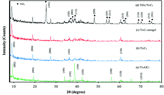 |
| | Fig. 1 XRD spectra of Ti3AlC2, Ti3C2 nanosheet, Ti3C2 aerogel and TiO2/Ti3C2 aerogel composite. | |
Nitrogen adsorption–desorption isotherms and pore size distributions of the prepared samples are shown in Fig. 2. All samples exhibit type-IV sorption isotherms indicating their mesoporous characteristics. At relative pressures of 0.4 and above, adsorption isotherms exhibit H3-type hysteresis loops which indicate plate-like particle aggregates and slit-like pores.45,46 High nitrogen adsorption was also observed at relative pressures of 0.9 and above for Ti3C2 aerogel, TiO2 and TiO2/Ti3C2 aerogel. Pore volumes and SBET values of Ti3C2, Ti3C2 aerogel, TiO2 and TiO2/Ti3C2 aerogel are 24 cm3 g−1, 93 cm3 g−1, 124 cm3 g−1, and 186 cm3 g−1, and 24.69 m2 g−1, and 48.61 m2 g−1, 64.84 m2 g−1, and 97.12 m2 g−1 respectively. The increase in pore volume and SBET from Ti3C2 to Ti3C2 aerogel was due to the introduction of additional porous networks during the morphology change from nanosheets to the aerogel structure. Formation of TiO2/Ti3C2 aerogel also involves the stacking of both porous structures which further enhances the porosity of the composite. All samples had a wide pore size distribution from 2 to 100 nm where TiO2 and Ti3C2 aerogel pore sizes generally peaked at 16 nm and 77 nm respectively.
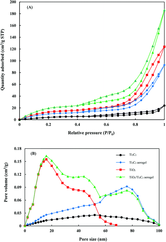 |
| | Fig. 2 BET isotherms (A) and pore size distributions (B) of the prepared samples. | |
Fig. 3(a) and (b) show the FESEM images of Ti3C2 MXene. The as-synthesised Ti3C2 sample had a laminar morphology where the nanosheet layers were separated and measured to have a thickness of 67 ± 8 nm. HF etching to remove the Al layer from the MAX phase releases H2 gas, causing the interlayer spacing of MXene nanosheets to increase and form an accordion-like structure.35 The MXene nanosheet layers were observed to be rough due to the extended HF etching and hydrothermal reaction.32,39 Some small nanoparticles were grown and dispersed on these rough surfaces. This could be attributed to the surface termination by hydroxyl and fluoride surface groups during HF etching and hydrothermal reaction:
| |  | (3) |
| | | Ti3C2 + 2H2O → Ti3C2(OH)2 + H2 | (4) |
| | | Ti3C2 + 2HF → Ti3C2F2 + H2 | (5) |
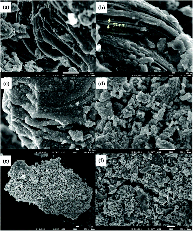 |
| | Fig. 3 FESEM images of (a and b) Ti3C2 MXene, (c and d) Ti3C2 MXene aerogel, and (e and f) TiO2/Ti3C2 MXene aerogel composite. | |
The formation of Ti3C2 MXene aerogel caused the nanosheets to be rougher and porous while retaining the typical MXene structure as shown in Fig. 3(c) and (d). These surface irregularities promote intimate contact of TiO2 on Ti3C2 MXene to form heterojunctions. The benefits of such surface segregation of TiO2 on the cocatalyst were also reported in another work by Cao et al. where such a technique resulted in their Cr-doped SrTiO3/Ti-doped α-Fe2O3 to have enhanced photoelectrochemical properties.47 The successful development of heterojunctions between TiO2 and Ti3C2 MXene was also observed in the SEM image of the TiO2/Ti3C2 MXene aerogel composite as shown in Fig. 3(e) and (f) where TiO2 dispersion on the surface and the surface irregularities of Ti3C2 MXene are seen. TiO2 nanoparticles were measured to have particle size in the range of 132.5 ± 30.8 nm and morphology of slab-like structure. The slab structures of TiO2 had surfaces significantly larger than their thickness, indicating higher exposure of the {001} facet than the {101} facet of TiO2.
Fig. 4 shows the TEM images of the catalyst samples. Fig. 4a shows the cross section of MXene nanosheet layers along with the surface terminations (Fig. 4b). Based on Fig. 4c, the cross section did not change during the formation of the Ti3C2 MXene aerogel structure but additional pores were observed as shown in Fig. 4d. TEM images of the composite sample indicate the dispersion of TiO2 over MXene aerogel for the development of heterojunctions. The sizes and structures of TiO2 and MXene as shown in the TEM images corroborate the aforementioned FESEM results. Elemental mapping analysis of the TiO2/Ti3C2 MXene aerogel composite indicated good segregation of Ti, O and C elements (Fig. 5). As oxygen originates from TiO2, this implies the good segregation of TiO2 over Ti3C2. EDX analysis of the TiO2/Ti3C2 MXene aerogel composite indicated the presence of Ti, C, O, F, Al and Cl elements. Al and Cl are minor elemental residues from the in situ HF etching using LiF and HCl. F is present as one of the surface terminations of Ti3C2 MXene. Based on EDX compositions, the effective TiO2 loading on the composite sample is 73.2 wt% which is close to the specified TiO2 loading during the synthesis stage.
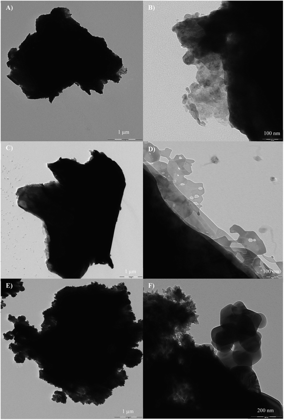 |
| | Fig. 4 TEM images of (A and B) Ti3C2 MXene, (C and D) Ti3C2 MXene aerogel, and (E and F) TiO2/Ti3C2 MXene aerogel composite. | |
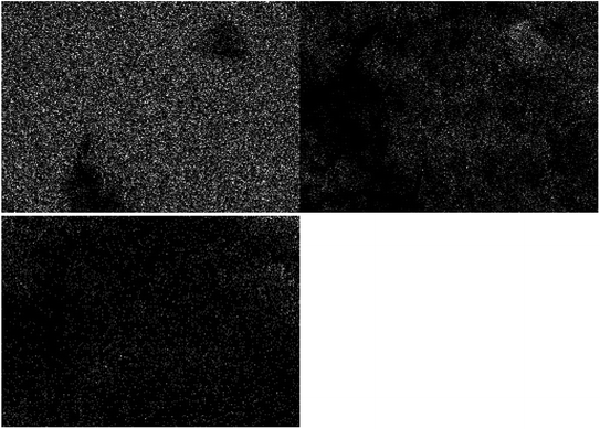 |
| | Fig. 5 Elemental mapping of Ti, O and C for the TiO2/Ti3C2 MXene aerogel composite. | |
3.2 Characterisation of POME
The POME sample extracted from the final discharge point of the palm oil milling process was a clear brown solution. A similar visual appearance was also reported in other works after aerobic treatment.4,48 Aerobic treatment was done at the final irrigation pond after the POME has been previously processed at the cooling pond, biogas digester pond, anaerobic pond, facultative pond and algae pond. These industrial treatments are sufficient to significantly reduce the properties of raw POME to meet the industrial discharge limit (Table 1). However, for a zero-pollutant discharge approach, the final discharged POME must be further reduced with additional treatment steps. For instance, membrane bioreactor, ultrafiltration and reverse osmosis systems are often employed to further convert the final discharged POME into clear water.4 However, these systems require significant investment for system commissioning and upkeep. Thus, photocatalysis of the POME was studied as an alternative in this work. Table 2 shows the types and the quantities of compounds identified in the POME sample via GC-MS analysis. Palmitic acid or n-hexadecanoic acid was identified as the major compound in POME as it is a natural major component of palm oil. Other compounds were also similarly reported in other works.49,50
Table 1 Characteristics and discharge limits of POME
| Parameters |
Present study |
Discharge limita |
Raw POME51 |
|
Limit of discharge refers to the current parameter limits for watercourse discharge of effluent from the rubber and palm oil abstracted from the Environmental Quality Act 1974 (Act 127) and Subsidiary Legislation 2002.
|
| pH |
8.38 |
5.0–9.0 |
3.4–5.2 |
| COD |
943 |
400 |
15![[thin space (1/6-em)]](https://www.rsc.org/images/entities/char_2009.gif) 000–100 000–100![[thin space (1/6-em)]](https://www.rsc.org/images/entities/char_2009.gif) 000 000 |
| BOD |
130 |
100 |
10![[thin space (1/6-em)]](https://www.rsc.org/images/entities/char_2009.gif) 250–43 250–43![[thin space (1/6-em)]](https://www.rsc.org/images/entities/char_2009.gif) 750 750 |
| Suspended solids |
320 |
400 |
5000–54![[thin space (1/6-em)]](https://www.rsc.org/images/entities/char_2009.gif) 000 000 |
| Oil and grease |
<1 |
50 |
130–180![[thin space (1/6-em)]](https://www.rsc.org/images/entities/char_2009.gif) 000 000 |
| Total solids |
6437 |
— |
11![[thin space (1/6-em)]](https://www.rsc.org/images/entities/char_2009.gif) 500–79 500–79![[thin space (1/6-em)]](https://www.rsc.org/images/entities/char_2009.gif) 000 000 |
| Ammoniacal nitrogen |
22.2 |
150 |
4–80 |
| Total nitrogen |
26.8 |
200 |
180–1400 |
Table 2 Identification of compounds in POME via GC-MS analysis
| Retention time (minute) |
Compound |
Molecular formula |
Molecular weight |
% |
| 4.301 |
Allyl ethyl ether |
C9H10O |
134.18 |
5.13 |
| 5.962 |
1-Buten-3-yne, 2-methyl- |
C5H6 |
66.10 |
1.55 |
| 11.095 |
4-Hydroxy-2-methylacetophenone |
C9H10O2 |
150.17 |
2.43 |
| 11.742 |
1-Ethyl-2,2,6-trimethylcyclohexane |
C11H22 |
154.29 |
0.51 |
| 11.842 |
Ethyl (Z)-non-3-enylcarbonate |
C12H22O3 |
214.30 |
1.56 |
| 15.052 |
Benzene, 1,4-dimethoxy-2-methyl- |
C9H12O2 |
152.19 |
1.87 |
| 19.953 |
1-Propanol, 2-methyl- |
C4H10O |
74.12 |
2.41 |
| 22.181 |
n-hexadecanoic acid |
C16H32O2 |
256.40 |
75.32 |
| 23.751 |
5-Octadecene, (E)- |
C18H36 |
252.49 |
5.23 |
| 33.654 |
Propylene oxide |
C3H6O |
58.08 |
2.62 |
| 37.369 |
1,4-Hexadiene, 3,3,5-trimethyl- |
C9H16 |
124.22 |
1.37 |
3.3 Photocatalytic degradation studies
The photocatalytic degradation of organic compounds in POME was performed to investigate the photocatalytic activity of the TiO2/Ti3C2 MXene composite aerogel under black light irradiation. In all three setups, POME solution was successfully treated and residual gas bubbles or foams were observed surrounding the meniscus of the solution after 24 h of photocatalytic reaction. GC-MS analysis of the extracted aliquots indicated similar identification of the organic compounds in POME as shown in Table 2 but with decreasing amounts over time due to further degradation and dilution of the remaining POME solution by water. The gas bubbles were tested to be of CO2 hence indicating the oxidation of organic compounds in POME into CO2 and water by the photocatalysts. During the adsorption phase, the photocatalyst samples are generally inactive, showing minimal effect on their photocatalytic activities. The POME degradation efficiencies in the dark cycle are 2%, 3% and 2.5% for TiO2, Ti3C2 aerogel and TiO2/Ti3C2 aerogel composite respectively. Based on Fig. 6, the order of photocatalytic degradation activity increases from TiO2 to Ti3C2 aerogel to the TiO2/Ti3C2 MXene aerogel composite. Ti3C2 is known for its excellent electrical conductivity where it promotes efficient charge migration and reduces electron–hole pair recombination as cocatalyst.39 Thus, the photocatalytic activity of the TiO2/Ti3C2 MXene aerogel composite was significantly higher as compared with that of Ti3C2 aerogel and TiO2.
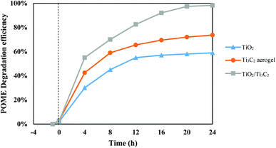 |
| | Fig. 6 POME degradation performances of TiO2, Ti3C2 aerogel and TiO2/Ti3C2. | |
After 24 h of photocatalytic reaction, a 98.3% POME degradation efficiency was achieved using the TiO2/Ti3C2 MXene aerogel composite, followed by 73.7% and 58.9% for Ti3C2 aerogel and TiO2 respectively. The graphs show significant POME degradation during the first 8 h of reaction. As the reaction progresses beyond 12 h, the degradation efficiency for all three setups begins to plateau due to the decreasing concentrations of dissolved oxygen and organic compounds. Having the photocatalytic setup constantly bubbled with an external oxygen source is expected to bring about higher POME degradation efficiency within shorter duration. With the use of an external oxygen source in other work, POME degradation efficiency was reported to reach more than 90% in 8 h of UV irradiation over Pt/TiO2.52 However, a limited oxygen condition was used in these setups to simulate the POME photocatalytic degradation under natural conditions with only solar irradiation and dissolved oxygen within the POME treatment pond.
The photostability of the photocatalyst composite was also investigated as it is one of the crucial criteria for its successful development and application. The photocatalytic degradation of POME over TiO2/Ti3C2 MXene composite aerogel was done cyclically for five identical runs with each run lasting for 24 h. Fig. 7 shows the cyclic photodegradation efficiency where the photocatalytic activity of the photocatalyst composite decreased marginally from 98.3% to 96% in the third run and beyond. Nevertheless, its photocatalytic performance remained very stable even after five runs which is equivalent to 120 h. Likewise, XRD analysis shows that the photocatalyst composite had no changes in phase structures before and after five runs of photocatalytic degradation, indicating the high stability of the catalyst (Fig. 8).
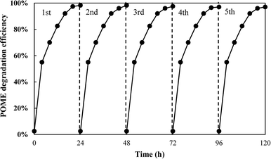 |
| | Fig. 7 Photostability test of the TiO2/Ti3C2 MXene aerogel composite for POME degradation. | |
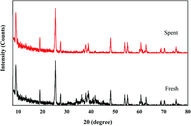 |
| | Fig. 8 XRD spectra of fresh and spent TiO2/Ti3C2 MXene aerogel composites. | |
3.4 Photocatalytic mechanism of {001}-TiO2/Ti3C2
Further insights on migration of photogenerated electrons from TiO2 to Ti3C2 were produced via DFT simulation results. The Fermi energy level, EF, is defined as:where Evac is the energy of a free electron at the vacuum level which was taken as 0 eV and W is the work function. The Ti3C2 work function was calculated to be 4.46 eV which gives an EF value of −4.46 eV vs. the vacuum level or −0.04 eV vs. the normal hydrogen electrode (NHE). The values of ECB and EVB of TiO2 were determined as follow:
where Eg is the bandgap (3.2 eV), χ is the Pearson absolute electronegativity (5.8 eV), and Ee is the energy of the free electron on the hydrogen scale (4.5 eV), thus giving ECB and EVB values of −0.3 eV and 2.9 eV vs. NHE respectively.
Fig. 9 shows a schematic of the TiO2/Ti3C2 heterojunction and its associated charge transfer mechanism. The TiO2/Ti3C2 heterojunction is a metal–semiconductor junction as TiO2 is an intrinsically n-type semiconductor and Ti3C2 is known to exhibit metallic behaviour.53,54 Under UV light irradiation, the exposed {001} facets of TiO2 excite electrons to the conduction band (CB), producing holes (h+) in the valence band (VB). As the ECB of TiO2 is more negative than the EF of Ti3C2, the migration of photogenerated electrons from TiO2 to Ti3C2 was made possible. This enables the separation of electron–hole pairs. The formation of a metal–semiconductor junction also involves the formation of a Schottky barrier due to the equalisation of Fermi energy levels during the intimate contact of both materials of different work functions. This will significantly reduce the recombination rate and achieve better spatial separation of photogenerated electron–hole pairs within the heterojunction. Against this backdrop, the photocatalytic activity of the TiO2/Ti3C2 MXene aerogel composite will be improved as demonstrated in Fig. 6. As the EF of Ti3C2 is close to the ECB, the reduction potential of photogenerated electrons was not reduced significantly thus preserving the redox potential of TiO2 for facile formation of reactive oxidation species.
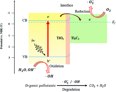 |
| | Fig. 9 Schematic diagram of charge transfer and photocatalytic degradation mechanisms via the TiO2/Ti3C2 heterojunction. | |
3.5 Degradation pathway and kinetics of POME
Fig. 10 shows the effect of radical scavengers on the concentration profile and the efficiency of POME degradation over the TiO2/Ti3C2 aerogel composite. With the addition of radical scavengers, the POME degradation efficiency was significantly inhibited in all cases to different extents. This indicated that each reactive oxidation species of h+, ·OH, ·O−2 and H2O2 has a crucial role in the POME degradation process. The extent of degradation inhibition was in the following order: IPA (27.6%) > BQ (42.9%) > AO (60.2%) > Fe(II)-EDTA (73.2%). Thus, the relative importance of reactive oxidation species for POME degradation can be placed in the following order: ·OH > ·O−2 > h+ > H2O2. These results indicate that the hydroxy radical is the most important reactive oxidation species for POME degradation which was also similarly reported by Ng et al.11
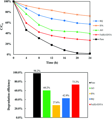 |
| | Fig. 10 Effect of radical scavengers on the POME degradation efficiency using the {001}-TiO2/Ti3C2 aerogel composite. | |
The photogenerated electrons in {001}-TiO2/Ti3C2 will reduce adsorbed oxygen to yield superoxide radical anions (·O−2) which further react with H+ and e− in a series of disproportionation and decomposition reactions (eqn. (9)–(14)) to yield hydroxyl radicals (·OH). The photogenerated holes will oxidise H2O and OH− into hydroxyl radicals (eqn (14)).55
| | | H2O2 + e− → OH− + ·OH | (12) |
Several reactive oxidation species such as superoxide (·O−2), peroxy (HO2·) and hydroxyl (·OH) radicals are formed during the degradation process.36 These radicals will interconvert to form the hydroxyl radical which is the most reactive intermediate for organic substrate oxidation. Fig. 11 shows the organic compounds present in POME. In principle, the hydroxyl radical will oxidise these organic compounds into CO2 and H2O where chain scission and ring cleavage are respectively occurring in aliphatic and aromatic hydrocarbons. Based on the GC-MS quantification of the compositions of organic compounds in POME, the POME degradation process can be expressed by the following empirical equation:
| | | C14.46H28.13O1.74 + 20.6225 O2 → 14.46 CO2 + 14.065 H2O | (15) |
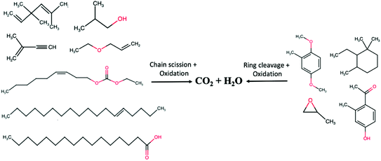 |
| | Fig. 11 Photocatalytic degradation of compounds in POME. | |
Kinetic data for POME photodegradation over the three catalyst samples were determined using the Langmuir–Hinshelwood (LH) rate law model. The reaction rate, rrxn, can be expressed as:
| |  | (16) |
where
k is the estimated rate constant (h
−1),
C is the representative POME and oxygen concentrations,
n is the reaction order and
K is the adsorption equilibrium constant. The denominator was approximated as the value of unity due to the low concentration of organics, thus reducing
eqn (16) into a typical
n-order elementary rate equation. By curve fitting suitable
n-order rate equations to the respective experimental data, TiO
2, Ti
3C
2 aerogel and TiO
2/Ti
3C
2 composite aerogel were found to follow the 5th, 3rd and 1st order of reaction (
Fig. 12). The equations were expressed as:
| |  | (17) |
| |  | (18) |
| |  | (19) |
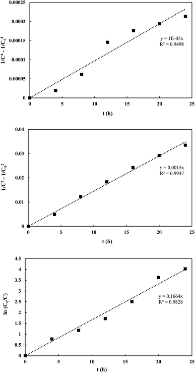 |
| | Fig. 12 Curve fitting of rate equations onto experimental data. | |
The respective values of R2 obtained were 0.9498, 0.9947 and 0.9828 which indicate good fitting of the proposed rate equations. The respective k values obtained were 2.5 × 10⁻⁶ h−1, 7.5 × 10⁻⁴ h−1 and 0.1664 h−1 in which the aerogel composite has the highest rate constant for POME degradation.
As POME is a solution of numerous organic model compounds, the rate orders obtained should be treated as representative values. However, the decrease in reaction order from 5th to 1st across the catalyst samples is an unusual trend where most of the papers commonly reported the adherence of pseudo-first order kinetics for POME degradation over other photocatalysts (Table 3). This could be due to the absence of external O2 bubbling in the current experimental setup to simulate a real open ponded photocatalytic degradation system which is different from other setups in previous studies which utilised constant external O2 bubbling. This setup will cause a limited O2 condition where O2 is no longer considered in excess and hence O2 concentration must be considered along with the concentration of organics within the kinetics. However, with the use of Ti3C2 composites, the effect of the limited O2 condition becomes less prominent due to a more efficient O2 uptake thus still being able to be approximated with pseudo-first order kinetics.
Table 3 Comparison of POME photocatalytic degradation systems
| Catalyst |
Degradation efficiency (%) |
Duration (min) |
Irradiation type |
Catalyst loading (g L−1) |
k (min−1) |
n
|
Ref. |
| Ag/TiO2 |
19.73 |
480 |
Visible |
1.5 |
6.61 × 10⁻⁴ |
1 |
11
|
| Pt/TiO2 |
90 |
480 |
UV |
1.0 |
1.34 × 10⁻³ |
1 |
52
|
| LaCa |
54.09 |
300 |
UV |
3.0 |
3.8 × 10⁻³ |
1 |
56
|
| BiVO4 |
25 |
250 |
UV |
1.0 |
1.5 × 10⁻³ |
1 |
57
|
| Nb2O5/ZnO |
91.7 |
240 |
UV |
— |
— |
— |
58
|
| TiO2/Ti3C2 aerogel |
98.3 |
1440 |
UV |
1.7 |
2.77 × 10⁻³ |
1 |
This work |
4 Conclusion
An efficient heterostructural TiO2/Ti3C2 MXene aerogel composite was successfully synthesised and applied in the photocatalytic degradation of POME. The composite was reported to have excellent photocatalytic activity for POME photodegradation as compared with pristine anatase TiO2 and Ti3C2 MXene. With the formation of Ti3C2 in aerogel form, characterisation results showed an increase in the surface roughness and porosity of the Ti3C2 structure which enhanced its contact with TiO2, producing interfacial heterojunctions. The interfacial heterojunction of {001}-TiO2 with Ti3C2 aerogel provided the synergy of Schottky-junction hole trapping and exposed active {001} TiO2 facets for enhanced photocatalytic activity. Photocatalytic degradation of POME was found to involve organic substrate oxidation by the reactive oxygen species which led to liberation of CO2 and water. With the use of black light irradiation and the absence of external oxygen bubbling, POME degradation was possible throughout the day which indicated the possibility of implementing such photocatalytic technology under natural ponding conditions. This work provides new insights on the application of TiO2 and MXene based photocatalysts for the final POME treatment to produce CO2 and water for further energy and material utilisation.
Conflicts of interest
There are no conflicts to declare.
Acknowledgements
This research is supported by the Ministry of Higher Education Malaysia through the Fundamental Research Grant Scheme (FRGS), project number FRGS/1/2022/TK09/XMU/03/2. The authors would also like to thank IChemE Palm Oil Processing Special Interest Group for their support through the POPSIG Student Research Project Bursary.
References
- J. M. Loh, Amelia, W. Gourich, C. L. Chew, C. P. Song and E.-S. Chan, Improved biodiesel production from sludge palm oil catalyzed by a low-cost liquid lipase under low-input process conditions, Renewable Energy, 2021, 177, 348–358 CrossRef CAS.
- Z. S. Lee, S. Y. Chin, J. W. Lim, T. Witoon and C. K. Cheng, Treatment technologies of palm oil mill effluent (POME) and olive mill wastewater (OMW): A brief review, Environ. Technol. Innovation, 2019, 15, 100377 CrossRef.
- S. Sani, A. F. Dashti and R. Adnan, Applications of Fenton oxidation processes for decontamination of palm oil mill effluent: A review, Arab. J. Chem., 2020, 13, 7302–7323 CrossRef CAS.
- J. Wang, Q. Mahmood, J.-P. Qiu, Y.-S. Li, Y.-S. Chang, L.-N. Chi and X.-D. Li, Zero discharge performance of an industrial pilot-scale plant treating palm oil mill effluent, BioMed Res. Int., 2015, 2015, 617861 Search PubMed.
- N. F. M. Hussein, C. Z. A. Abidin, F. M. Ridwan, S. N. Sabri and N. A. Razali, Comparative study on palm oil mill effluent (POME) treatment by electro-oxidation using catalyst and electrode, AIP Conf. Proc., 2019, 2157, 020018 CrossRef CAS.
- N. Z. Zainuri, N. H. H. Hairom, D. A. B. Sidik, A. L. Desa, N. Misdan, N. Yusof and A. W. Mohammad, Palm oil mill secondary effluent (POMSE) treatment via photocatalysis process in presence of ZnO-PEG nanoparticles, J. Water Proc. Eng., 2018, 26, 10–16 CrossRef.
- K. H. Ng, Adoption of TiO2-photocatalysis for palm oil mill effluent (POME) treatment: Strengths, weaknesses, opportunities, threats (SWOT) and its practicality against traditional treatment in Malaysia, Chemosphere, 2021, 270, 129378 CrossRef CAS PubMed.
- M. A. Norhan, S. R. S. Abdullah, H. A. Hasan and N. I. Ismail, A constructed wetland system for bio-polishing palm oil mill effluent and its future research opportunities, J. Water Proc. Eng., 2021, 41, 102043 CrossRef.
- W. H. Saputera, A. F. Amri, R. Daiyan and D. Sasongko, Photocatalytic technology for palm oil mill effluent (POME) wastewater treatment: Current progress and future perspective, Materials, 2021, 14, 2846 CrossRef CAS PubMed.
- N. A. Lokman, A. M. Ithnin, W. J. Yahya and M. A. Yuzir, A brief review on biochemical oxygen demand (BOD) treatment methods for palm oil mill effluents (POME), Environ. Technol. Innovation, 2021, 21, 101258 CrossRef CAS.
- K. H. Ng, C. H. Lee, M. R. Khan and C. K. Cheng, Photocatalytic degradation of recalcitrant POME waste by using silver doped titania: Photokinetics and scavenging studies, Chem. Eng. J., 2016, 286, 282–290 CrossRef CAS.
- K. H. Ng, L. S. Yuan, C. K. Cheng, K. Chen and C. Fang, TiO2 and ZnO photocatalytic treatment of palm oil mill effluent (POME) and feasibility of renewable energy generation: A short review, J. Clean. Prod., 2019, 233, 209–225 CrossRef CAS.
- K. H. Ng, M. R. Khan, Y. H. Ng, S. S. Hossain and C. K. Cheng, Restoration of liquid effluent from oil palm agroindustry in Malaysia using UV/TiO-2 and UV/ZnO photocatalytic systems: A comparative study, J. Environ. Manage., 2017, 196, 674–680 CrossRef CAS PubMed.
- O. Arutanti, A. A. Sari, A. Berkah, M. Nurdin, M. A. Fitriady, Y. Parmawati, N. Rinaldi, A. Yuniarto and T. Hadibarata, Advanced degradation of lignin from palm oil mill effluent (POME) by a combination of photocatalytic-fenton treatment and TiO2 nanoparticle as the catalyst, Water, Air, Soil Pollut., 2020, 231, 266 CrossRef CAS.
- M. Haji Alhaji, K. Sanaullah, S. Fong Lim, A. Ragai Henry Rigit, A. Hamza and A. Khan, Modeling and optimization of photocatalytic treatment of pre-treated palm oil mill effluent (POME) in a UV/TiO2 system using response surface methodology (RSM), Cogent Engineering, 2017, 4, 1382980 CrossRef.
- R. Nawaz, F. K. Chong, Y. C. Ho, M. H. Isa and W. H. Lim, Restoration of pretreated palm oil mill effluent using TiO2 based photocatalytic system: An optimization study, IOP Conf. Ser.: Mater. Sci. Eng., 2020, 736, 042035 CAS.
-
I. Fondriest, Environmental, Solar Radiation and Photosynethically Active Radiation, 2014 Search PubMed.
- Y. Lu, X. Ou, W. Wang, J. Fan and K. Lv, Fabrication of TiO2 nanofiber assembly from nanosheets (TiO2-NFs-NSs) by electrospinning-hydrothermal method for improved photoreactivity, Chin. J. Catal., 2020, 41, 209–218 CrossRef CAS.
- A. Meng, L. Zhang, B. Cheng and J. Yu, Dual cocatalysts in TiO2 photocatalysis, Adv. Mater., 2019, 31, 1807660 CrossRef PubMed.
- Q. Guo, C. Zhou, Z. Ma and X. Yang, Fundamentals of TiO2 photocatalysis: Concepts, mechanisms, and challenges, Adv. Mater., 2019, 31, 1901997 CrossRef CAS PubMed.
- J. Peng, X. Chen, W.-J. Ong, X. Zhao and N. Li, Surface and heterointerface engineering of 2D MXenes and their nanocomposites: Insights into electro- and photocatalysis, Chem, 2019, 5, 18–50 CAS.
- J. Y. Zhang, H. G. Liao and S. G. Sun, Construction of 1D/1D WO3 Nanorod/TiO2 Nanobelt Hybrid Heterostructure for Photocatalytic Application, Chin. J. Struct. Chem., 2020, 39, 1019–1028 CAS.
- Y. L. Chen, Y. X. Xu, D. F. Lin, Y. J. Luo, H. Xue and Q. H. Chen, Insight into Superior Visible Light Photocatalytic Activity for Degradation of Dye over Corner-truncated Cubic Ag2O Decorated TiO2 Hollow Nanofibers, Chin. J. Struct. Chem., 2020, 39, 588–597 CAS.
- X. W. S. L. Jiabi Li, Fluorinated TiO2 Hollow Photocatalysts for Photocatalytic Applications, Acta Phys.-Chim. Sin., 2021, 37, 2009038 Search PubMed.
- X. Zhang, J. Shao, C. Yan, R. Qin, Z. Lu, H. Geng, T. Xu and L. Ju, A review on optoelectronic device applications of 2D transition metal carbides and nitrides, Mater. Des., 2021, 200, 109452 CrossRef CAS.
- Y. Gong, X. Xing, Y. Wang, Z. Lv, Y. Zhou and S.-T. Han, Emerging MXenes for functional memories, Small Science, 2021, 1, 2100006 CrossRef.
- B. Anasori, M. R. Lukatskaya and Y. Gogotsi, 2D metal carbides and nitrides (MXenes) for energy storage, Nat. Rev. Mater., 2017, 2, 16098 CrossRef CAS.
- K. Huang, C. Li, H. Li, G. Ren, L. Wang, W. Wang and X. Meng, Photocatalytic applications of two-dimensional Ti3C2 MXenes: A review, ACS Appl. Nano Mater., 2020, 3, 9581–9603 CrossRef CAS.
- Y. Li, D. Zhang, X. Feng, Y. Liao, Q. Wen and Q. Xiang, Truncated octahedral bipyramidal TiO2/MXene Ti3C2 hybrids with enhanced photocatalytic H2 production activity, Nanoscale Adv., 2019, 1, 1812–1818 RSC.
- H. Li, B. Sun, T. Gao, H. Li, Y. Ren and G. Zhou, Ti3C2 MXene co-catalyst assembled with mesoporous TiO2 for boosting photocatalytic activity of methyl orange degradation and hydrogen production, Chin. J. Catal., 2022, 43, 461–471 CrossRef CAS.
- Y. Li, X. Deng, J. Tian, Z. Liang and H. Cui, Ti3C2 MXene-derived Ti3C2/TiO2 nanoflowers for noble-metal-free photocatalytic overall water splitting, Appl. Mater. Today, 2018, 13, 217–227 CrossRef.
- A. Shahzad, K. Rasool, M. Nawaz, W. Miran, J. Jang, M. Moztahida, K. A. Mahmoud and D. S. Lee, Heterostructural TiO2/Ti3C2Tx (MXene) for photocatalytic degradation of antiepileptic drug carbamazepine, Chem. Eng. J., 2018, 349, 748–755 CrossRef CAS.
- C. Peng, X. Yang, Y. Li, H. Yu, H. Wang and F. Peng, Hybrids of two-dimensional Ti3C2 and TiO2 exposing {001} facets toward enhanced photocatalytic activity, ACS Appl. Mater. Interfaces, 2016, 8, 6051–6060 CrossRef CAS PubMed.
- Y. Gao, L. Wang, A. Zhou, Z. Li, J. Chen, H. Bala, Q. Hu and X. Cao, Hydrothermal synthesis of TiO2/Ti3C2 nanocomposites with enhanced photocatalytic activity, Mater. Lett., 2015, 150, 62–64 CrossRef CAS.
- M. Alhabeb, K. Maleski, B. Anasori, P. Lelyukh, L. Clark, S. Sin and Y. Gogotsi, Guidelines for synthesis and processing of two-dimensional titanium carbide (Ti3C2Tx MXene), Chem. Mater., 2017, 29, 7633–7644 CrossRef CAS.
-
S. Malato-Rodríguez, Solar detoxification and disinfection. in Encyclopedia Of Energy, ed. C. J. Cleveland; Elsevier, New York, 2004; Vol. pp. 587–596 Search PubMed.
- W. Feng, H. Luo, S. Zeng, C. Chen, L. Deng, Y. Tan, X. Zhou, S. Peng and H. Zhang, Ni-modified Ti3C2 MXene with enhanced microwave absorbing ability, Mater. Chem. Front., 2018, 2, 2320–2326 RSC.
- M. Naguib, M. Kurtoglu, V. Presser, J. Lu, J. Niu, M. Heon, L. Hultman, Y. Gogotsi and M. W. Barsoum, Two-dimensional nanocrystals produced by exfoliation of Ti3AlC2, Adv. Mater., 2011, 23, 4248–4253 CrossRef CAS PubMed.
- H. Fang, Y. Pan, M. Yin and C. Pan, Enhanced visible light photocatalytic activity of CdS with alkalized Ti-3C2 nano-sheets as co-catalyst for degradation of rhodamine B, J. Mater. Sci.: Mater. Electron., 2019, 30, 14954–14966 CrossRef CAS.
- W. Wan, R. Zhang, M. Ma and Y. Zhou, Monolithic aerogel photocatalysts: a review, J. Mater. Chem. A, 2018, 6, 754–775 RSC.
- A. S. Jatoi, Z. Hashmi, S. A. Mazari, R. Abro and N. Sabzoi, Recent developments and progress of aerogel assisted environmental remediation: a review, J. Porous Mater., 2021, 28, 1919–1933 CrossRef CAS.
- P. Lin, J. Xie, Y. He, X. Lu, W. Li, J. Fang, S. Yan, L. Zhang, X. Sheng and Y. Chen, MXene aerogel-based phase change materials toward solar energy conversion, Sol. Energy Mater. Sol. Cells, 2020, 206, 110229 CrossRef CAS.
- K.-J. Lee, Y.-J. Choe, Y. H. Kim, J. K. Lee and H.-J. Hwang, Fabrication of silica aerogel composite blankets from an aqueous silica aerogel slurry, Ceram. Int., 2018, 44, 2204–2208 CrossRef CAS.
- A. N. Kay Lup, F. Abnisa, W. M. A. W. Daud and M. K. Aroua, Synergistic interaction of metal–acid sites for phenol hydrodeoxygenation over bifunctional Ag/TiO2 nanocatalyst, Chin. J. Chem. Eng., 2019, 27, 349–361 CrossRef.
- M. Thommes, K. Kaneko, A. V. Neimark, J. P. Olivier, F. Rodriguez-Reinoso, J. Rouquerol and K. S. W. Sing, Physisorption of gases, with special reference to the evaluation of surface area and pore size distribution (IUPAC Technical Report), Pure Appl. Chem., 2015, 87, 1051–1069 CrossRef CAS.
- J. Low, J. Yu, Q. Li and B. Cheng, Enhanced visible-light photocatalytic activity of plasmonic Ag and graphene co-modified Bi2WO6 nanosheets, Phys. Chem. Chem. Phys., 2014, 16, 1111–1120 RSC.
- D. Cao, J. Zhang, A. Wang, X. Yu and B. Mi, Fabrication of Cr-doped SrTiO3/Ti-doped α-Fe2O3 photoanodes with enhanced photoelectrochemical properties, J. Mater. Sci. Technol., 2020, 56, 189–195 CrossRef.
- Z. S. Lee, C. K. Cheng and S. Y. Chin, Hydrothermal treatment of palm oil mill effluent (POME) under oxidative and non-oxidative conditions, IOP Conf. Ser.: Mater. Sci. Eng., 2020, 965, 012002 CrossRef CAS.
- Y. W. Cheng, Z. S. Lee, C. C. Chong, M. R. Khan, C. K. Cheng, K. H. Ng and S. S. Hossain, Hydrogen-rich syngas production via steam reforming of palm oil mill effluent (POME) – A thermodynamics analysis, Int. J. Hydrogen Energy, 2019, 44, 20711–20724 CrossRef CAS.
- J. Cheng, X. Zhu, J. Ni and A. Borthwick, Palm oil mill effluent treatment using a two-stage microbial fuel cells system integrated with immobilized biological aerated filters, Bioresour. Technol., 2010, 101, 2729–2734 CrossRef CAS PubMed.
- A. Ahmad, R. Ghufran and Z. A. Wahid, Bioenergy from anaerobic degradation of lipids in palm oil mill effluent, Rev. Environ. Sci. Bio/Technol., 2011, 10, 353–376 CrossRef CAS.
- C. K. Cheng, M. Rizauddin Derahman and M. R. Khan, Evaluation of the photocatalytic degradation of pre-treated palm oil mill effluent (POME) over Pt-loaded titania, J. Environ. Chem. Eng., 2015, 3, 261–270 CrossRef CAS.
- H. Kim and H. N. Alshareef, MXetronics: MXene-Enabled Electronic and Photonic Devices, ACS Mater. Lett., 2020, 2, 55–70 CrossRef CAS.
- V. C. Anitha, A. N. Banerjee and S. W. Joo, Recent developments in TiO2 as n- and p-type transparent semiconductors: synthesis, modification, properties, and energy-related applications, J. Mater. Sci., 2015, 50, 7495–7536 CrossRef CAS.
- H. Wang, X. Li, X. Zhao, C. Li, X. Song, P. Zhang, P. Huo and X. Li, A review on heterogeneous photocatalysis for environmental remediation: From semiconductors to modification strategies, Chin. J. Catal., 2022, 43, 178–214 CrossRef CAS.
- S. Shariah Ghazali, R. Jusoh and J. Haslinda Shariffuddin, Parameter Affecting Photocatalytic Degradation of POME using LaCa as Photocatalyst, Mater. Today: Proc., 2019, 19, 1173–1182 CAS.
- W. H. Saputera, A. F. Amri, R. R. Mukti, V. Suendo, H. Devianto and D. Sasongko, Photocatalytic Degradation of Palm Oil Mill Effluent (POME) Waste Using BiVO4 Based Catalysts, Molecules, 2021, 26, 6225 CrossRef CAS PubMed.
- Y.-H. Chin, J.-C. Sin and S.-M. Lam, A facile route for fabrication of hierarchical porous Nb2O5/ZnO composites with enhanced photocatalytic degradation of palm oil mill effluent, Mater. Lett., 2018, 216, 8–11 CrossRef CAS.
|
| This journal is © The Royal Society of Chemistry 2022 |
Click here to see how this site uses Cookies. View our privacy policy here.  Open Access Article
 *ab
*ab
![[thin space (1/6-em)]](https://www.rsc.org/images/entities/char_2009.gif) 250–43
250–43![[thin space (1/6-em)]](https://www.rsc.org/images/entities/char_2009.gif) 750) and COD (15
750) and COD (15![[thin space (1/6-em)]](https://www.rsc.org/images/entities/char_2009.gif) 000–100
000–100![[thin space (1/6-em)]](https://www.rsc.org/images/entities/char_2009.gif) 000) which makes it a much more significant water pollutant than municipal sewage.4 Additionally, POME is rich in palm oil based organic compounds such as carotenes, carboxylic acids, pectin, lignin and phenolics which are harmful to the ecological environment.3,5–7 Furthermore, POME can be difficult to handle, as the production of POME often occurs on a massive scale and the conventional POME treatment method is ineffective where a long duration is needed for POME degradation.8,9
000) which makes it a much more significant water pollutant than municipal sewage.4 Additionally, POME is rich in palm oil based organic compounds such as carotenes, carboxylic acids, pectin, lignin and phenolics which are harmful to the ecological environment.3,5–7 Furthermore, POME can be difficult to handle, as the production of POME often occurs on a massive scale and the conventional POME treatment method is ineffective where a long duration is needed for POME degradation.8,9![[thin space (1/6-em)]](https://www.rsc.org/images/entities/char_2009.gif) :
:![[thin space (1/6-em)]](https://www.rsc.org/images/entities/char_2009.gif) Eu phosphor mixture with spectral bandwidth at 370 ± 20 nm and 404 nm to simulate the UV-visible light irradiation from sunlight. Two mL solution was extracted from the reaction system every 4 hours and centrifuged to remove the photocatalyst. The aliquot was then analysed using gas chromatography-mass spectrometry (GC-MS) analysis. As the POME solution undergoes photocatalytic degradation, it is expected to produce CO2 and water with a gradual decrease in POME solution via organic substrate oxidation with the following empirical equation:36
Eu phosphor mixture with spectral bandwidth at 370 ± 20 nm and 404 nm to simulate the UV-visible light irradiation from sunlight. Two mL solution was extracted from the reaction system every 4 hours and centrifuged to remove the photocatalyst. The aliquot was then analysed using gas chromatography-mass spectrometry (GC-MS) analysis. As the POME solution undergoes photocatalytic degradation, it is expected to produce CO2 and water with a gradual decrease in POME solution via organic substrate oxidation with the following empirical equation:36

![[thin space (1/6-em)]](https://www.rsc.org/images/entities/char_2009.gif) :
:![[thin space (1/6-em)]](https://www.rsc.org/images/entities/char_2009.gif) 50 was used. The GC column temperature was raised from 323 K to 473 K at 8 K min−1 and subsequently to 573 K at 10 K min−1. Organic compounds in POME samples were then identified using the NIST mass spectral library.
50 was used. The GC column temperature was raised from 323 K to 473 K at 8 K min−1 and subsequently to 573 K at 10 K min−1. Organic compounds in POME samples were then identified using the NIST mass spectral library.


![[thin space (1/6-em)]](https://www.rsc.org/images/entities/char_2009.gif) 000–100
000–100![[thin space (1/6-em)]](https://www.rsc.org/images/entities/char_2009.gif) 000
000![[thin space (1/6-em)]](https://www.rsc.org/images/entities/char_2009.gif) 250–43
250–43![[thin space (1/6-em)]](https://www.rsc.org/images/entities/char_2009.gif) 750
750![[thin space (1/6-em)]](https://www.rsc.org/images/entities/char_2009.gif) 000
000![[thin space (1/6-em)]](https://www.rsc.org/images/entities/char_2009.gif) 000
000![[thin space (1/6-em)]](https://www.rsc.org/images/entities/char_2009.gif) 500–79
500–79![[thin space (1/6-em)]](https://www.rsc.org/images/entities/char_2009.gif) 000
000


