An experimental high temperature thermal battery coupled to a low temperature metal hydride for solar thermal energy storage
Received
19th July 2019
, Accepted 5th November 2019
First published on 5th November 2019
Abstract
Metal hydrides have demonstrated ideal physical properties to be the next generation of thermal batteries for solar thermal power plants. Previous studies have demonstrated that they already operate at the required operational temperature and offer greater energy densities than existing technology. Thermal batteries using metal hydrides need to store hydrogen gas released during charging, and so far, practical demonstrations have employed volumetric storage of gas. This practical study utilises a low temperature metal hydride, titanium manganese hydride (TiMn1.5Hx), to store hydrogen gas, whilst magnesium iron hydride (Mg2FeH6) is used as a high temperature thermal battery. The coupled system is able to achieve consistent energy storage and release cycles. With titanium manganese hydride operating at ambient temperature (20 °C), Mg2FeH6 has to operate between ∼350 °C and ∼500 °C to counteract the pressure hysteresis displayed by TiMn1.5 between hydrogen uptake and release. The results attest the high susceptibility of both materials to thermal issues, such as a requirement for large temperature offsets, in order for the battery to achieve full cycling capacity. An energy density of 1488 kJ kg−1 was experimentally attained for 40 g of Mg2FeH6 with a maximum operating temperature around 520 °C.
Introduction
The total global electrical energy consumption has been steadily increasing over the last 30 years.1 Many alternative renewable energy sources have been developed in order to reduce the use of conventional fossil fuels while still covering the ever growing energy demand. Concentrating solar power (CSP) plants represent one of the most promising technologies to meet base load power demands and have undergone continuous growth since the beginning of this century.2,3 To enable 24/7 energy production, an integrated thermal energy storage (TES) is mandatory to ensure a steady daily production of electricity during natural weather variations or night time.4
Sensible heat storage has most commonly been used in past and present CSP projects, with operating temperature ranging between 290 °C and 565 °C.2,5,6 However, more attention is being paid to latent heat and thermochemical storage technologies. Thermochemical energy storage, such as the reversible hydrogenation of a metal, presents the advantage of higher energy storage density and lower thermal losses over extended periods.7–9 Heating a metal hydride (MH) induces desorption of hydrogen, and this endothermic reaction can be adopted as a heat storage process. The released hydrogen can be stored and remains available for when the thermal battery starts to cool down. This temperature drop drives a re-absorption of hydrogen and the exothermic absorption process is utilised for heat discharge. The reversible hydrogenation of a metal to produce a MH is amongst the most energy dense chemical reactions. For example, magnesium iron hydride (Mg2FeH6), with an enthalpy of reaction of 77.4 kJ mol−1 H2, could offer up to 6 times more energy than the same volume of molten salt at an operating temperature of 565 °C.8,10 As such, magnesium based materials have been studied as potential high temperature MH (HTMH) and some have shown good reversibility between 400 °C and 500 °C.10–13 Magnesium iron hydride, on a gram scale, has already been proven to have a stable reversible hydrogen capacity over 600 cycles, at temperatures up to 555 °C, under hydrogen pressures ranging from 63 to 75 bar.10 In addition, recent studies have demonstrated the ease of synthesis of this material from plain steel with magnesium metal.14 A medium scale, 211 g reactor was reported by Urbanczyk et al., where consistent hydrogen capacity was exhibited.15 High energy capacity retention is mandatory where longevity is crucial in an industrial application (30 years). Hence further studies towards industrial applications with this material are worthwhile.
The cost-effective and practical storage of hydrogen gas released from a HTMH remains a challenge that requires further investigation. The large amount of gas to store, around 1100 m3 for storing 1 MWhth in magnesium hydride,16 may mean that the use of traditional hydrogen tanks are cost prohibitive, which would also require the addition of a gas compressor into the system.17 Some studies suggest the use of underground cavities for hydrogen gas storage, which could offer simplicity and large capacity at mild cost.17 However, these solutions may not always be practical. Low temperature metal hydrides (LTMH) offer a more versatile solution to gas storage, and seem to be promising given their high hydrogen storage capacity at ambient temperature, i.e. 130 kg m−3 of H2 for LaNi5.18 LTMH's have been studied intensively during the past decade due to the renewed interest in hydrogen energy and fuel cells.18–20 The wide range of compounds that reversibly store hydrogen at low temperature (20 °C to 100 °C), should allow the chemical tuning of a suitable low temperature material for a specific application. When used to store hydrogen desorbed by a HTMH, a LTMH needs to operate within the same pressure range, and ideally at around ambient temperature. LaNi5 type interstitial hydrides are able to store hydrogen at ambient temperature but the high content of rare earth metals engender heavy costs, especially for the large quantities required for TES. One study details that to store 158 kg H2, the cost of the LaNi5 would be $655![[thin space (1/6-em)]](https://www.rsc.org/images/entities/char_2009.gif) 000 USD compared to $65
000 USD compared to $65![[thin space (1/6-em)]](https://www.rsc.org/images/entities/char_2009.gif) 000 USD for TiMn1.5.21 However, prices are subject to change over time and based on location and quantity. Sodium based hydrides, such as sodium alanate, may meet the requirement as a LTMH and have been investigated in thermal energy modelling studies.22,23 However, sodium alanate operates around 150 °C at 30 bar of hydrogen pressure, which introduces an additional requirement of a LTMH heat supply and therefore supplementary costs. Some intermetallic hydride such as TiFeHx could also be of interest.24 However, it also requires an elevated temperature above 55 °C to operate above 10 bar.25 Titanium manganese hydrides (TiMn1.5 and its multicomponent derivatives) have shown limited degradation (∼20%) in capacity over 10
000 USD for TiMn1.5.21 However, prices are subject to change over time and based on location and quantity. Sodium based hydrides, such as sodium alanate, may meet the requirement as a LTMH and have been investigated in thermal energy modelling studies.22,23 However, sodium alanate operates around 150 °C at 30 bar of hydrogen pressure, which introduces an additional requirement of a LTMH heat supply and therefore supplementary costs. Some intermetallic hydride such as TiFeHx could also be of interest.24 However, it also requires an elevated temperature above 55 °C to operate above 10 bar.25 Titanium manganese hydrides (TiMn1.5 and its multicomponent derivatives) have shown limited degradation (∼20%) in capacity over 10![[thin space (1/6-em)]](https://www.rsc.org/images/entities/char_2009.gif) 000 cycles, which represents over 30 years of daily usage.26 This degradation has been largely attributed to surface poisoning by gaseous impurities rather than formation of a stable hydride phase. As the hydrogen in a CSP system is not consumed, gaseous poisoning should be limited. In addition, a Ti–Mn alloy was paired with NaMgH2F in a TES simulation and projected the system to be able to store 585 kJ kg−1 at a temperature around 600 °C and pressure ranging between 40 and 60 bar.27 However, the physical properties used for their simulations didn't take into account the pressure hysteresis phenomenon that results in a sloping equilibrium plateau during both desorption and absorption, which was later underlined by Murshidi et al.28
000 cycles, which represents over 30 years of daily usage.26 This degradation has been largely attributed to surface poisoning by gaseous impurities rather than formation of a stable hydride phase. As the hydrogen in a CSP system is not consumed, gaseous poisoning should be limited. In addition, a Ti–Mn alloy was paired with NaMgH2F in a TES simulation and projected the system to be able to store 585 kJ kg−1 at a temperature around 600 °C and pressure ranging between 40 and 60 bar.27 However, the physical properties used for their simulations didn't take into account the pressure hysteresis phenomenon that results in a sloping equilibrium plateau during both desorption and absorption, which was later underlined by Murshidi et al.28
The operating principle of a coupled HTMH–LTMH system to store thermal energy is based on the autonomous exchange of hydrogen gas without involving mechanical moving parts. A similar concept exists for other thermal energy storage technologies.29 While the system stores thermal energy, the temperature of the HTMH first rises until it induces an endothermic hydrogen release. The quantity of hydrogen gas is substantial and it must be stored and remain available for an exothermic gas absorption reaction when thermal energy is required, which will occur when the temperature of HTMH drops below a certain level. For the complete system to be autonomous, the gas storage system must provide an on-demand hydrogen supply or storage following the HTMH absorption or desorption, respectively. Coupling a LT hydride to the HT hydride can meet this requirement and offer remarkable volumetric hydrogen densities. Fig. 1 portrays a hypothetical van't Hoff diagram illustrating the operational requirements of a coupled LTMH and HTMH. At the initial state of the system, the HTMH is fully hydrogenated and set to its minimum working temperature. The LTMH is dehydrogenated and stands at ambient temperature. The system is inactive when the temperature and pressure are at condition (1). As thermal energy enters the system (e.g. day time) and the heat storage process starts (1 to 2), the temperature of the HTMH is increased leading to dehydrogenation of the hydride. This causes the system gas pressure to increase and consequently the LTMH starts hydrogenation when the gas pressure is above its equilibrium pressure. It should be noted that this too is an exothermic reaction that produces thermal energy which must be dissipated to the environment. When the HTMH has fully desorbed (maximum thermal energy stored), an isobaric temperature increase takes place if further heating occurs (2 to 3), while the LTMH, which is fully loaded with hydrogen, starts to cool down. When the HTMH temperature drops (e.g. night time), the subsequent lowering of its equilibrium pressure activates the exothermic hydrogen absorption process. If the energy generated by the reaction is insufficient to maintain temperature, the gas absorption continues until the hydride is fully formed (3 to 4). Meanwhile, the LTMH, providing the hydrogen to maintain the equilibrium pressure of the HTMH, endures a reduction in temperature due to the endothermic nature of hydrogen desorption.
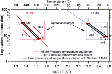 |
| | Fig. 1 Ideal cycle of selected HTMH and LTMH coupled along with their respective van't Hoff plots (1 to 4 represent specific steps of the heat storage and release which are detailed in text). | |
The present study describes an experimental study of a coupled HTMH–LTMH system for TES application. Mg2FeH6 stores the thermal energy (HTMH) and as such is provided with heat at high temperatures (∼350 °C to ∼520 °C). The second MH, titanium manganese based, is employed as a LTMH, which acts as a hydrogen gas store with a high volumetric density. The thermal response of the MH's and the flow of hydrogen between both are presented. The influence of different operational parameters (thermal parameters, gas back pressure) are examined to optimise the system and offer a better understanding of the reaction dynamics. The study aims to explore the feasibility of coupling these hydrides and the constraints involved to use their full hydrogen storage capacities.
Experimental
Material preparation
A titanium manganese alloy (Ti0.97Zr0.019V0.439–Fe0.097Cr0.045Al0.026Mn1.5 also known as TiMn1.5, Sigma-Aldrich, hydrogen storage grade, Alloy 5800) was chosen as the LTMH for its range of working pressure at ambient temperatures.28 From 5 bar at 10 °C to 30 bar at 30 °C, it matches the equilibrium pressures of magnesium iron hydride for operating temperature between 350 °C and 450 °C, respectively 4 bar and 28 bar.10,28 To avoid any oxygen contamination of air sensitive materials, all samples were manipulated inside a glovebox filled with argon, in which H2O/O2 levels were kept below 1 ppm. Mg2FeH6 was prepared by reacting 2 moles of Mg (Sigma-Aldrich, >98%, powder) with one mole of Fe (Sigma-Aldrich, >99%, powder). As Bogdanović et al. reported for magnesium hydrogen system, the reduction of particle size can improve hydrogenation rate by a factor of 6.30 Hence, the mixture was ball milled for 2 hours, under argon atmosphere, in a 316 stainless steel Turbula T2C shaker mill with a ball to powder ratio of 5![[thin space (1/6-em)]](https://www.rsc.org/images/entities/char_2009.gif) :
:![[thin space (1/6-em)]](https://www.rsc.org/images/entities/char_2009.gif) 1. The milled powder was then placed in a 316 stainless steel reactor. The HTMH was cycled 3 times at 460 °C with absorption carried out at 60 bar and desorption under atmospheric pressure causing the following the reaction:
1. The milled powder was then placed in a 316 stainless steel reactor. The HTMH was cycled 3 times at 460 °C with absorption carried out at 60 bar and desorption under atmospheric pressure causing the following the reaction:| | | 2Mg + Fe + 3H2 → Mg2FeH6 | (1) |
The TiMn1.5 alloy was hydrogenated as-supplied at room temperature (25 °C) under 50 bar of hydrogen pressure for one hour then placed under dynamic vacuum for one hour. This operation was repeated 5 times to achieve consistent hydrogen kinetics and capacity.
Material characterisation
X-ray diffraction (XRD, Bruker D8 advance, Cu-Kα1+2 radiation, λ = 1.5418 Å) was conducted on the prepared hydrides, detected by a LynxEye 3° linear position sensitive detector (PSD) with 192 pixels. A 2θ acquisition range was typically between 20° and 80°. To prevent sample oxidation occurring during data acquisition, samples were loaded into an air-tight spherically capped poly-methylmethacrylate (PMMA) sample holder. The sample holder caused a broad hump in the diffraction profile in the region where 2θ equals 20°. This was taken into account during the background definition in Topas (Bruker AXS) prior to the X-ray profile analysis.
Design of experimental lab scale system
The dedicated hydrogen sorption apparatus was set up to measure the pressure of hydrogen in the whole system as well as the hydrogen flow between the HTMH (magnesium iron hydride) and the LTMH (titanium manganese alloy) (Fig. 2). Each of the hydrides were encapsulated in a 316 stainless steel cylinder of 2.54 cm outer diameter (with 0.2 cm of wall thickness), with a 0.6 cm diameter stainless steel porous rod (pore size = 1 μm, SIKA-R IS, GKN Sinter Metals Filters GmbH) positioned at the centre of each cylinder to maximise hydrogen diffusion through the powder bed. The 20 cm long HTMH reactor was filled with 40.7 g of a ball-milled mixture of 2Mg + Fe. The whole reactor was placed in an insulated furnace to guarantee isothermal heating. The HTMH reactor was connected to the LTMH reactor and an initial pressure of 8 bar H2 was loaded. The 7 cm long LTMH reactor was filled with 85.2 g of dehydrogenated titanium manganese alloy. The LTMH reactor was submerged in a stirred ambient water bath to minimise the temperature differential across the reactor. The hydrogen capacity of the intermetallic hydride is dependent on operating temperature, however it averages 1.7 wt% H2 within the range of 20 °C to 40 °C.28 This provides a hydrogen capacity of the LTMH reactor of around 1.5 g of hydrogen. K-type thermocouples were embedded in the powders of both reactors to monitor the core temperature of each metal hydride. A pressure transducer (Rosemount 3051SMV) was employed to measure the absolute pressure and differential pressure across a 100 μm orifice (Lenox Laser). The free gas volume was determined using an externally calibrated volume to be 93 ± 5 mL. The hydrogen mass flow was determined using the pressure differential Δp in the following relation (2):31| |  | (2) |
where: C: discharge coefficient, β (0.021): ratio between orifice and pipe diameter, ε (∼1): expansibility factor, d (0.01 cm): orifice diameter, Δp (Pa): instant differential pressure, ρ (kg m−3): gas density.32
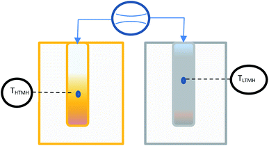 |
| | Fig. 2 Schematic of the thermal battery using coupled HTMH and LTMH with pressure differential measurement. | |
Results and discussion
Synthesis
The literature offers a number of production methods for magnesium iron hydride from the two base metals.10,12,14,33–37 The initial temperature and pressure parameters were varied to elect an annealing process providing the highest yield of the hydride. The XRD patterns presented in Fig. 3 represent three different annealing procedures. These patterns were acquired after 3 absorption/desorption cycles. For each designated temperature (i.e.: 500 °C, 460 °C and 450 °C), the samples were kept for one hour under the associated pressure load for absorption (80 bar, 60 bar and 40 bar H2 respectively) and one hour under 1 bar H2 pressure for desorption. The plots allow a phase identification and quantification through the Rietveld refinement technique from XRD data. Results show that at 500 °C and 80 bar H2 (Fig. 3a), Mg2FeH6 was synthesised at a greater than 85% yield. A similar result is found at 460 °C, with an 80% yield at 60 bar H2 (Fig. 3b) but only a 22% yield at 40 bar H2 (Fig. 3c). The latter reveals predominant formation of MgH2. The 460 °C and 60 bar H2 parameter are considered satisfactory for the annealing of the whole 40.7 g of Mg2FeH6. Based on a 80% yield of Mg2FeH6, a 4.4 wt% hydrogen capacity is assumed, meaning the HTMH was able to react with ≈1.8 g of hydrogen.35
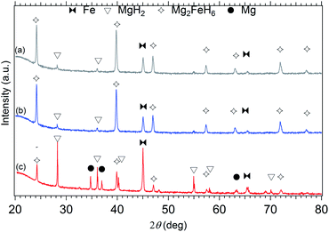 |
| | Fig. 3 X-ray diffraction pattern for synthesis of Mg2FeH6, (a) 500 °C – 80 bar H2, (b) 460 °C – 60 bar H2, (c) 450 °C – 40 bar H2. Cu-Kα1+2 radiation, λ = 1.5418 Å. | |
Thermally cycling the HTMH with an ambient LTMH
In a closed system with the HTMH at equilibrium conditions of pressure and temperature, theoretically, if the HTMH temperature increases it induces a hydrogen desorption and system pressure therefore increases. As the pressure in the system increases, it becomes higher than the equilibrium pressure of the LTMH, causing the hydrogen gas in the system to be absorbed by the LTMH. Fig. 4 represents three cycles of hydrogen desorption and absorption of the HTMH for temperatures set to vary between ≈450 °C and 350 °C (Fig. 4a). The global response of system gas pressure is consistent over the cycles, where it fluctuates between 8 bar and 26 bar H2 (Fig. 4c). The LTMH temperature also follows a consistent profile throughout the cycles. The rapid HTMH heating rate (10 °C min−1) generates a large flow of hydrogen gas (Fig. 4d), reaching above 1 g h−1, and is responsible for a sharp temperature rise in the LTMH from 20 °C to ∼27 °C (Fig. 4b). This rapid response demonstrates the ability of the LTMH to quickly absorb the hydrogen gas desorbed by the HTMH. After the initial rapid event, the hydrogen flow drops and the LTMH starts to cool down to ambient. As the enthalpy of reaction is low for the LTMH, 21.4 kJ mol−1 H2,28 the energy generated by the absorption of the remaining hydrogen is dissipated by the water bath. When the HTMH temperature is lowered, the hydrogen reabsorption process starts, although the thermal response of the LTMH is not as intense while it supplies hydrogen more gradually. Due to the thermal isolation of the HTMH, cooling is a much slower mechanism than heating. As such, the hydrogen flow during HTMH cooling is lower and doesn't exceed 0.5 g h−1. The repeatable hydrogen flow can be integrated to estimate the total hydrogen mass transferred between both hydrides. Fig. 5 presents the reacted fraction determined by integrating hydrogen flow from cycles presented in Fig. 4. It is based on the expected 1.85 g of hydrogen available from the Mg2FeH6 sample. Only 0.90 g of hydrogen, half capacity, was able to flow through the system, while 0.15 g was retained to elevate the system pressure up to 26 bar, which satisfies the equilibrium pressure of the HTMH at 450 °C. This impedes the full hydrogen release of the HTMH. The LTMH absorbed 0.80 g of hydrogen, which is 53% of its maximum hydrogen capacity. Due to hysteresis of the LTMH at 20 °C, the system pressure would have to reach over 30 bar to ensure a full uptake by the LTMH.28 This could be obtained by minimising the free gas volume or increasing the maximum HTMH temperature.
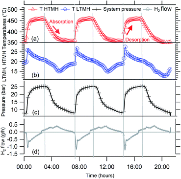 |
| | Fig. 4 (a) HTMH temperatures, (b) LTMH temperatures, (c) system pressure, (d) hydrogen flow 3 cycles when HTMH temperature oscillate between 350 °C and 450 °C. | |
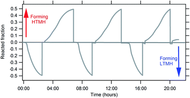 |
| | Fig. 5 Reacted fraction evolution of the HTMH (Mg2FeH6) and LTMH (TiMn1.5) for cycles presented in Fig. 4. | |
A system discrepancy
Despite the possibility of increasing the HTMH temperature, a discrepancy specific to this metal hydride coupling during heat storage has been noted, and deserves an explanation. In Fig. 6, one desorption and absorption cycle is plotted alongside the calculated temperature/pressure equilibrium curves in a van't Hoff plot. On the left, the HTMH follows the equilibrium curve during desorption before a slight isobaric temperature increase (Fig. 6a), followed by a pressure increase despite the nearly constant temperature of the HTMH (Fig. 6b). On the right of Fig. 6, the temperature/pressure profile of the LTMH is depicted. The LTMH exhibits a high degree of pressure hysteresis, therefore additional calculated equilibrium profiles (multiple straight lines in Fig. 6) are necessary to completely reflect the pressure limitations during hydrogen cycling. As such, equilibrium pressure–temperature lines along the LTMH cycle show the predicted equilibrium pressure when the material is fully/half de/hydrogenated. The LTMH profile just exceeds the van't Hoff plot corresponding to the mid absorption, which agrees with the 53% of capacity reached for this cycling parameter (HTMH cycling between ∼350 °C and ∼450 °C). However, a sharp isobaric temperature drop occurs during the LTMH absorption process (Fig. 6c). As presented in Fig. 7, it coincides with a reduction in hydrogen flow after reaching around 1 g h−1 (Fig. 7a). The fast HTMH heating rate (10 °C min−1) releases the first 0.5 g H2 in less than an hour when the whole 0.90 g is desorbed in 3 hours. The consistent temperature rise in the LTMH is generated by a fast hydrogen absorption which stops as the hydrogen flow drops (Fig. 7a), due to a lack of heat generation, then a LTMH cooling phase appears as the hydrogen flow decreases. It reveals the synchronicity between the heat extraction required for the LTMH with the thermal power stored in the HTMH.
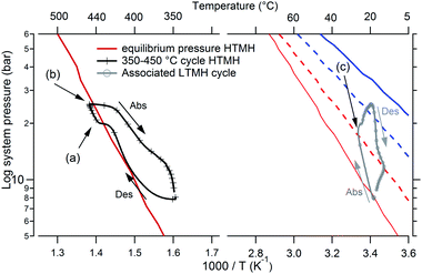 |
| | Fig. 6 HTMH and LTMH cycle presented in a van't Hoff diagram, HTMH (left), LTMH (right), along with their respective calculated equilibrium pressure plots (blue line: fully hydrogenated, blue dash: mid absorption; red line: fully dehydrogenated, red dash: mid desorption). Des: desorption, Abs: absorption. | |
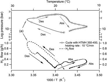 |
| | Fig. 7 System pressure and hydrogen flow versus LTMH temperature for similar HTMH operating between ∼350–450 °C. Abs: absorption, Des: desorption. | |
System optimisation
A higher gas pressure (ballast) in the entire system would allow more hydrogen to be absorbed by the LTMH and thus also affect the operation of the HTMH and aid in achieving full hydrogen cycling capacity. To achieve this, three operational parameters can be adjusted: (i) increasing the maximum HTMH temperature, (ii) change of free gas volume and (iii) cycling with LTMH at elevated temperature.
(i) Increasing the maximum HTMH temperature.
Increasing the maximum temperature of the HTMH also increases the maximum equilibrium pressure it exhibits. This could potentially increase the hydrogen mass released by the HTMH, where hydrogen gas can theoretically be released until this equilibrium pressure is met. As a consequence of more hydrogen gas being released, the LTMH would absorb a greater portion of this hydrogen. Fig. 8 details four representative cycles that were undertaken with different maximum HTMH temperatures. The system gas pressure and the LTMH temperature differential increases accordingly. It reveals the hydrogen mass desorbed from the HTMH for each cycle along with the calculated mass of hydrogen that causes an overall increase of the global system pressure. The hydrogen mass absorbed by the LTMH is also presented.
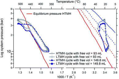 |
| | Fig. 8 HTMH between ∼350 °C and ∼500 °C (left) and LTMH (right) with original and added free volume; along with their respective calculated equilibrium pressure plots (blue line: fully hydrogenated, blue dash: mid absorption; red line: fully dehydrogenated, red dash: mid desorption). | |
A substantial extension of the HTMH temperature range (cycling between around 350 °C and 500 °C) leads to the HTMH desorbing 1.65 g of hydrogen, almost reaching its expected hydrogen capacity of 4.4 wt% (yield obtained with the selected annealing procedure). This quantity of hydrogen raises the overall system pressure and also increases the mass of hydrogen absorbed by the LTMH to around 95% of its capacity. This 150 °C temperature differential is large, but necessary to overcome the hysteresis phenomenon observed between the LTMH absorption and desorption process. Considering the enthalpy of reaction of the Mg2FeH6 HTMH is 77.4 kJ mol−1 H2, the practical energy storage capacity observed in this study is 1488 kJ kg−1.8 This is 71.2% of the maximum theoretical value that is expected for a HTMH with a gravimetric H2 capacity of 5.47 wt%. The energy to be dissipated from the LTMH would be 180 kJ kg−1 based on its enthalpy of absorption of 21.7 kJ mol−1 H2.28 In the case of the Crescent Dunes CSP plant, operating in Nevada desert, 32![[thin space (1/6-em)]](https://www.rsc.org/images/entities/char_2009.gif) 000 tons of molten salts are required to store 13
000 tons of molten salts are required to store 13![[thin space (1/6-em)]](https://www.rsc.org/images/entities/char_2009.gif) 200 GJ of thermal energy that drives a steam turbine with average efficiency of 30%. The capacity determined for Mg2FeH6 would allow energy storage between ∼350 and 500 °C to be reduced in mass to only 8500 tons of HTMH.38 However, given the 1.5 wt% capacity displayed by the LTMH, this plant would require around 22
200 GJ of thermal energy that drives a steam turbine with average efficiency of 30%. The capacity determined for Mg2FeH6 would allow energy storage between ∼350 and 500 °C to be reduced in mass to only 8500 tons of HTMH.38 However, given the 1.5 wt% capacity displayed by the LTMH, this plant would require around 22![[thin space (1/6-em)]](https://www.rsc.org/images/entities/char_2009.gif) 000 tons of LTMH to store the hydrogen involved in the heat storing process.
000 tons of LTMH to store the hydrogen involved in the heat storing process.
(ii) Change of free gas volume.
The free gas volume is also a parameter that can affect the efficiency of the coupled hydride system. This volume sustains pressure variations throughout each cycle and also diverts a small amount of gas. It can create a volumetric buffer as well as a hindrance that inhibits a raise in the overall system gas pressure. In this coupled metal hydride system, the LTMH requires a high pressure differential to be effective, due to its hysteresis, and therefore suggests optimised operation with minimal free gas volume. However, the current experimental set up only allows for an increase in the free volume. Therefore an additional volume of 56.8 mL was introduced to the system, loaded with 8 bar of hydrogen and experiments were reproduced using the previous parameters exhibited in Fig. 7. Fig. 8 presents, in a van't Hoff plot, the HTMH cycling between a minimum of 350 °C and maximum of 500 °C, along with the associated LTMH response for the system with and without an added free volume. The overall cycle profile is similar for both the HTMH and the LTMH. The addition of a free volume diminishes the maximum gas pressure reached by the system from 37.1 bar to 32.5 bar (Table 2) due to its ability to hold more gas in its larger volume. Table 2 collates the original data set from Table 1 (without additional volume) with the data that includes the additional 56.8 mL volume operated at identical temperatures. The addition of a free volume doesn't influence the thermal variations of the LTMH. As presented in Table 1, a larger free volume induces a decrease of the maximum attained pressure, the hydrogen mass desorbed from the HTMH remains equivalent. As expected, the mass of hydrogen absorbed by the LTMH also drops with the increase in free volume since the additional volume captures more hydrogen. The volume prevents the required pressure rise to use optimal capacity of the LTMH, thus affecting its efficiency. According to previous thermodynamic studies, if the free gas volume was negligible, full capacity of both hydrides could be obtained with a reduced thermal excursion on the HTMH: between 390 °C and 450 °C would allow the LTMH to operate at temperatures around 20 °C.28
Table 1 Comparison of parameters affected by varying the operational temperature of the HTMH (temperatures and pressures carry a 2% uncertainty; hydrogen masses carry a 5% uncertainty)
| HTMH temperature (°C) |
LTMH temperature (°C) |
Gas pressure (bar) |
HTMH |
Hydrogen mass causing a system pressure increase (g) |
LTMH |
| Min |
Max |
DT |
Min |
Max |
Min |
Max |
Desorbed mass of H2 (g) |
Absorbed H2 mass (g) |
| 350 |
410 |
60 |
18 |
22 |
7.2 |
14.5 |
0.40 |
0.05 |
0.35 |
| 350 |
455 |
105 |
15 |
27 |
7.5 |
26.0 |
0.90 |
0.13 |
0.75 |
| 350 |
480 |
130 |
17 |
32 |
8.5 |
30.0 |
1.30 |
0.16 |
1.10 |
| 350 |
500 |
150 |
14 |
32.5 |
8.5 |
37.5 |
1.65 |
0.21 |
1.45 |
Table 2 Comparison of parameters affected by free volume variations (temperatures and pressures carry a 2% uncertainty; hydrogen masses carry a 5% uncertainity)
| Free volume (mL) |
HTMH temperature (°C) |
LTMH temperature (°C) |
Pressure (bar) |
HTMH |
Hydrogen causing system pressure raise (g) |
LTMH |
| Min |
Max |
Min |
Max |
Min |
Max |
Desorbed H2 mass (g) |
Absorbed H2 mass (g) |
| 93 |
350 |
455 |
15 |
27 |
7.5 |
26 |
0.90 |
0.14 |
0.75 |
| 150 |
350 |
455 |
16 |
26.5 |
8 |
23.5 |
0.80 |
0.19 |
0.60 |
| 93 |
350 |
500 |
14 |
32.5 |
8.5 |
37.5 |
1.65 |
0.22 |
1.45 |
| 150 |
350 |
500 |
15 |
32.5 |
10 |
32.5 |
1.60 |
0.28 |
1.30 |
(iii) Cycling with LTMH at elevated temperature.
It is also possible to regulate the LTMH temperature to evaluate its effect on hydrogen uptake. In theory, a higher operating temperature entails an increase in the LTMH equilibrium pressure. For example, a fully desorbed LTMH at an average temperature of 30 °C is stable at around 12 bar H2 (or below); at 29 bar H2 system pressure, the LTMH reaches half absorbing capacity and can be fully hydrogenated at 42 bar H2. However the LTMH discrepancy needs to be verified when this hydride is operating at varying average temperatures. Fig. 9, presents the HTMH (∼350 to ∼450 °C) and LTMH cycles with LTMH temperatures regulated around 20 °C, 30 °C and 40 °C by submerging the LTMH vessel in a temperature controlled water bath. When the LTMH is maintained at 30 °C, 2 thermal anomalies are caused by the water heater regulation (Fig. 9a). Operating the LTMH at an elevated temperature tends to smooth its thermal profile over the cycle and erase the discrepancy occurring at the average LTMH temperature of 20 °C. However, at 20 °C, 30 °C and 40 °C the hydrogen mass able to flow through the LTMH diminishes from 0.90 g, to 0.80 g, and 0.65 g for the LTMH, respectively. It reveals the fundamental influence of the temperature levels on the systems overall capacity, and emphasises the thermal management of a large scale installation as a key parameter. A full HTMH desorption was reached when cycled between around 360 °C and 520 °C while the LTMH has an average temperature of 30 °C. For these conditions, the pressure fluctuated between 9 bar and 40.5 bar, although almost 0.3 g of hydrogen is retained by the free gas volume, but the LTMH absorbed nearly 1.5 g, which equates to its maximum expected capacity. Even if the thermal excursion is higher than for a LTMH operating around 20 °C, this demonstrates the possibility of thermo-regulating the LTMH to increase the operating temperature of the HTMH.
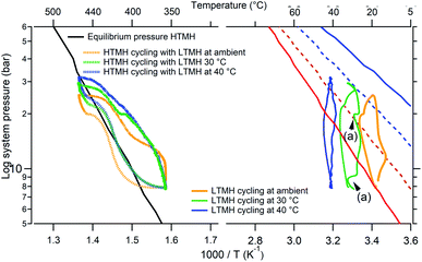 |
| | Fig. 9 HTMH (left) and LTMH (right) cycle for different LTMH average temperatures (ambient, 20 °C, 40 °C); along with their respective calculated equilibrium pressure plots (blue line: fully hydrogenated, blue dash: mid absorption; red line: fully dehydrogenated, red dash: mid desorption). (a) shows a thermal anomaly caused by the water heater. | |
Conclusions
A solar thermal energy storage system utilising a coupled metal hydride system has been demonstrated. Mg2FeH6 was used as the high temperature metal hydride (HTMH) and TiMn1.5 as the low temperature metal hydride (LTMH, hydrogen storage). The study revealed that the HTMH was able to release and store hydrogen into the LTMH when temperature and pressure parameters are finely tuned. Moreover, the LTMH offers crucially fast reaction kinetics allowing responsive hydrogen release and uptake to and from the HTMH. The pairing of Mg2FeH6 with TiMn1.5 at ambient temperature, allowed the system to reach 71.2% of the HTMH theoretical thermal energy capacity, offering 1488 kJ kg−1 of TES. In order to match the operating conditions of the LTMH, it was necessary to set the minimum temperature of HTMH to nearly 350 °C and heat it up to around 500 °C, with a 150 °C temperature range being imperative in generating the required gas pressure differential. An increase of the LTMH operating temperature to 30 °C, instead of 20 °C, allowed the maximum operating temperature of the HTMH to be elevated to ∼520 °C, utilising nearly full hydrogen capacity of both hydrides. The hysteresis of the LTMH is the cause for the large temperature differentials in the HTMH due to the requirement of generating large over- and under-pressures from the HTMH. For a large scale paired system, one must take this phenomenon into account, where a LTMH with little to no hysteresis and a flat plateau is preferable. The large HTMH temperature variation is also due to the presence of a fixed free gas volume, which limits the ability of the HTMH to generate differences in system gas pressure. This constraint is mainly due to the overall small scale, which should be negligible for technological scale-up.
Conflicts of interest
There are no conflicts to declare.
Acknowledgements
CEB and MP acknowledge the financial support of the Australian Research Council (ARC) for Linkage Project LP120101848, and LP, TDH and CEB also acknowledge funding from the ARC for LP150100730 and ARC LIEF grants LE0989180 and LE0775551, which enabled the XRD and gas sorption studies to be conducted. MP also acknowledges the ARC for Future Fellowship FT160100303. The authors acknowledge the facilities and technical assistance of the Microscopy & Microanalysis Facility of the John de Laeter Centre at Curtin University.
Notes and references
-
M. Metayer, C. Breyer and H.-J. Fell, presented in part at the 31st European Photovoltaic Solar Energy Conference and Exhibition, Hamburg, Germany, 2015 Search PubMed.
- M. T. Islam, N. Huda, A. B. Abdullah and R. Saidur, Renewable Sustainable Energy Rev., 2018, 91, 987–1018 CrossRef.
- U. Pelay, L. Luo, Y. Fan, D. Stitou and M. Rood, Renewable Sustainable Energy Rev., 2017, 79, 82–100 CrossRef.
- A. J. Carrillo, J. González-Aguilar, M. Romero and J. M. Coronado, Chem. Rev., 2019, 119, 4777–4816 CrossRef CAS PubMed.
- Y. Tian and C. Y. Zhao, Appl. Energy, 2013, 104, 538–553 CrossRef CAS.
- E. González-Roubaud, D. Pérez-Osorio and C. Prieto, Renewable Sustainable Energy Rev., 2017, 80, 133–148 CrossRef.
- P. Pardo, A. Deydier, Z. Anxionnaz-Minvielle, S. Rougé, M. Cabassud and P. Cognet, Renewable Sustainable Energy Rev., 2014, 32, 591–610 CrossRef CAS.
- K. Manickam, P. Mistry, G. Walker, D. Grant, C. E. Buckley, T. D. Humphries, M. Paskevicius, T. Jensen, R. Albert, K. Peinecke and M. Felderhoff, Int. J. Hydrogen Energy, 2019, 44, 7738–7745 CrossRef CAS.
- D. A. Sheppard, M. Paskevicius, T. D. Humphries, M. Felderhoff, G. Capurso, J. B. von Colbe, M. Dornheim, T. Klassen, P. A. Ward, J. A. Teprovich, C. Corgnale, R. Zidan, D. M. Grant and C. E. Buckley, Appl. Phys. A, 2016, 122, 395 CrossRef.
- B. Bogdanović, A. Reiser, K. Schlichte, B. Spliethoff and B. Tesche, J. Alloys Compd., 2002, 345, 77–89 CrossRef.
- K. Ikeda, Y. Kogure, Y. Nakamori and S. Orimo, Scr. Mater., 2005, 53, 319–322 CrossRef CAS.
- V. A. Yartys, M. V. Lototskyy, E. Akiba, R. Albert, V. E. Antonov, J. R. Ares, M. Baricco, N. Bourgeois, C. E. Buckley, J. M. Bellosta von Colbe, J. C. Crivello, F. Cuevas, R. V. Denys, M. Dornheim, M. Felderhoff, D. M. Grant, B. C. Hauback, T. D. Humphries, I. Jacob, T. R. Jensen, P. E. de Jongh, J. M. Joubert, M. A. Kuzovnikov, M. Latroche, M. Paskevicius, L. Pasquini, L. Popilevsky, V. M. Skripnyuk, E. Rabkin, M. V. Sofianos, A. Stuart, G. Walker, H. Wang, C. J. Webb and M. Zhu, Int. J. Hydrogen Energy, 2019, 44, 7809–7859 CrossRef CAS.
- L. Poupin, T. D. Humphries, M. Paskevicius and C. E. Buckley, Sustainable Energy Fuels, 2019, 3, 985–995 RSC.
- M. Polanski, D. Nawra and D. Zasada, J. Alloys Compd., 2019, 776, 1029–1040 CrossRef CAS.
- R. Urbanczyk, M. Meggouh, R. Moury, K. Peinecke, S. Peil and M. Felderhoff, Appl. Phys. A, 2016, 122, 315 CrossRef.
- M. Paskevicius, D. A. Sheppard and C. E. Buckley, J. Am. Chem. Soc., 2010, 132, 5077–5083 CrossRef CAS PubMed.
- D. A. Sheppard and C. E. Buckley, Int. J. Hydrogen Energy, 2019, 44, 9143–9163 CrossRef CAS.
- A. Züttel, Mater. Today, 2003, 6, 24–33 CrossRef.
-
J. Reilly, Metal hydrides as hydrogen storage media and their applications, Report BNL-21648, Brookhaven National Lab, USA, 1976 Search PubMed.
- V. Bérubé, G. Radtke, M. Dresselhaus and G. Chen, Int. J. Energy Res., 2007, 31, 637–663 CrossRef.
- D. N. Harries, M. Paskevicius, D. A. Sheppard, T. E. C. Price and C. E. Buckley, Proc. IEEE, 2012, 100, 539–549 CAS.
- A. d'Entremont, C. Corgnale, M. Sulic, B. Hardy, R. Zidan and T. Motyka, Int. J. Hydrogen Energy, 2017, 42, 22518–22529 CrossRef.
- D. A. Sheppard, T. D. Humphries and C. E. Buckley, Appl. Phys. A, 2016, 122, 406 CrossRef.
- M. D. K. Dewa, S. Wiryolukito and H. Suwarno, Energy Procedia, 2015, 68, 318–325 CrossRef CAS.
- J. Reilly and R. Wiswall, Inorg. Chem., 1974, 13, 218–222 CrossRef CAS.
- T. Gamo, Y. Moriwaki, N. Yanagihara and T. Iwaki, J. Less-Common Met., 1983, 89, 495–504 CrossRef CAS.
- A. d'Entremont, C. Corgnale, B. Hardy and R. Zidan, Int. J. Hydrogen Energy, 2018, 43, 817–830 CrossRef.
- J. A. Murshidi, M. Paskevicius, D. A. Sheppard and C. E. Buckley, Int. J. Hydrogen Energy, 2011, 36, 7587–7593 CrossRef CAS.
-
S. T. Kim, C. Kurahashi, H. Hoshino, C. Takahashi, Y. Tamura, H. Takasu, S. Saito, M. Kurihara and Y. Kato, Thermal Driving Demonstration of Li4SiO4/CO2/Zeolite Thermochemical Energy Storage System for Efficient High-Temperature Heat Utilizations, 2019 Search PubMed.
- B. Bogdanović, K. Bohmhammel, B. Christ, A. Reiser, K. Schlichte, R. Vehlen and U. Wolf, J. Alloys Compd., 1999, 282, 84–92 CrossRef.
-
R. C. Baker, An introductory Guide to Flow Measurement, John Wiley & Sons, 2002 Search PubMed.
-
I. Bell, NIST Reference Fluid Thermodynamic and Transport Properties Database (REFPROP) Version9 - SRD 23, National Institute of Standards and Technology Search PubMed.
- L. Farina, S. Brutti, F. Trequattrini, O. Palumbo, S. Gatto, P. Reale, L. Silvestri, S. Panero and A. Paolone, Int. J. Hydrogen Energy, 2017, 42, 22333–22341 CrossRef CAS.
- Z. A. Matysina, S. Y. Zaginaichenko, D. V. Shchur and M. T. Gabdullin, Russ. Phys. J., 2016, 59, 177–189 CrossRef CAS.
- K. Witek, K. Karczewski, M. Karpowicz and M. Polanski, Crystals, 2018, 8, 94 CrossRef.
- T. D. Humphries, D. A. Sheppard and C. E. Buckley, Coord. Chem. Rev., 2017, 342, 19–33 CrossRef CAS.
- J. Huot, F. Cuevas, S. Deledda, K. Edalati, Y. Filinchuk, T. Grosdidier, B. C. Hauback, M. Heere, T. R. Jensen, M. Latroche and S. Sartori, Materials, 2019, 12, 2778 CrossRef PubMed.
- M. Fellet, C. E. Buckley, M. Paskevicius and D. A. Sheppard, MRS Bull., 2013, 38, 1012–1013 CrossRef CAS.
|
| This journal is © The Royal Society of Chemistry 2020 |
 ,
Terry D.
Humphries
 *,
Mark
Paskevicius
 and
Craig E.
Buckley

![[thin space (1/6-em)]](https://www.rsc.org/images/entities/char_2009.gif) 000 USD compared to $65
000 USD compared to $65![[thin space (1/6-em)]](https://www.rsc.org/images/entities/char_2009.gif) 000 USD for TiMn1.5.21 However, prices are subject to change over time and based on location and quantity. Sodium based hydrides, such as sodium alanate, may meet the requirement as a LTMH and have been investigated in thermal energy modelling studies.22,23 However, sodium alanate operates around 150 °C at 30 bar of hydrogen pressure, which introduces an additional requirement of a LTMH heat supply and therefore supplementary costs. Some intermetallic hydride such as TiFeHx could also be of interest.24 However, it also requires an elevated temperature above 55 °C to operate above 10 bar.25 Titanium manganese hydrides (TiMn1.5 and its multicomponent derivatives) have shown limited degradation (∼20%) in capacity over 10
000 USD for TiMn1.5.21 However, prices are subject to change over time and based on location and quantity. Sodium based hydrides, such as sodium alanate, may meet the requirement as a LTMH and have been investigated in thermal energy modelling studies.22,23 However, sodium alanate operates around 150 °C at 30 bar of hydrogen pressure, which introduces an additional requirement of a LTMH heat supply and therefore supplementary costs. Some intermetallic hydride such as TiFeHx could also be of interest.24 However, it also requires an elevated temperature above 55 °C to operate above 10 bar.25 Titanium manganese hydrides (TiMn1.5 and its multicomponent derivatives) have shown limited degradation (∼20%) in capacity over 10![[thin space (1/6-em)]](https://www.rsc.org/images/entities/char_2009.gif) 000 cycles, which represents over 30 years of daily usage.26 This degradation has been largely attributed to surface poisoning by gaseous impurities rather than formation of a stable hydride phase. As the hydrogen in a CSP system is not consumed, gaseous poisoning should be limited. In addition, a Ti–Mn alloy was paired with NaMgH2F in a TES simulation and projected the system to be able to store 585 kJ kg−1 at a temperature around 600 °C and pressure ranging between 40 and 60 bar.27 However, the physical properties used for their simulations didn't take into account the pressure hysteresis phenomenon that results in a sloping equilibrium plateau during both desorption and absorption, which was later underlined by Murshidi et al.28
000 cycles, which represents over 30 years of daily usage.26 This degradation has been largely attributed to surface poisoning by gaseous impurities rather than formation of a stable hydride phase. As the hydrogen in a CSP system is not consumed, gaseous poisoning should be limited. In addition, a Ti–Mn alloy was paired with NaMgH2F in a TES simulation and projected the system to be able to store 585 kJ kg−1 at a temperature around 600 °C and pressure ranging between 40 and 60 bar.27 However, the physical properties used for their simulations didn't take into account the pressure hysteresis phenomenon that results in a sloping equilibrium plateau during both desorption and absorption, which was later underlined by Murshidi et al.28
![[thin space (1/6-em)]](https://www.rsc.org/images/entities/char_2009.gif) :
:![[thin space (1/6-em)]](https://www.rsc.org/images/entities/char_2009.gif) 1. The milled powder was then placed in a 316 stainless steel reactor. The HTMH was cycled 3 times at 460 °C with absorption carried out at 60 bar and desorption under atmospheric pressure causing the following the reaction:
1. The milled powder was then placed in a 316 stainless steel reactor. The HTMH was cycled 3 times at 460 °C with absorption carried out at 60 bar and desorption under atmospheric pressure causing the following the reaction:


![[thin space (1/6-em)]](https://www.rsc.org/images/entities/char_2009.gif) 000 tons of molten salts are required to store 13
000 tons of molten salts are required to store 13![[thin space (1/6-em)]](https://www.rsc.org/images/entities/char_2009.gif) 200 GJ of thermal energy that drives a steam turbine with average efficiency of 30%. The capacity determined for Mg2FeH6 would allow energy storage between ∼350 and 500 °C to be reduced in mass to only 8500 tons of HTMH.38 However, given the 1.5 wt% capacity displayed by the LTMH, this plant would require around 22
200 GJ of thermal energy that drives a steam turbine with average efficiency of 30%. The capacity determined for Mg2FeH6 would allow energy storage between ∼350 and 500 °C to be reduced in mass to only 8500 tons of HTMH.38 However, given the 1.5 wt% capacity displayed by the LTMH, this plant would require around 22![[thin space (1/6-em)]](https://www.rsc.org/images/entities/char_2009.gif) 000 tons of LTMH to store the hydrogen involved in the heat storing process.
000 tons of LTMH to store the hydrogen involved in the heat storing process.


