 Open Access Article
Creative Commons Attribution 3.0 Unported Licence
PEDOT:PSS materials for optoelectronics, thermoelectrics, and flexible and stretchable electronics
Xi
Fan
 a,
Nathan E.
Stott
 a,
Jixi
Zeng
a,
Yunfei
Li
a,
Jianyong
Ouyang
a,
Jixi
Zeng
a,
Yunfei
Li
a,
Jianyong
Ouyang
 *b,
Liang
Chu
e and
Weijie
Song
 *acd
*acd
aNingbo Institute of Materials Technology and Engineering, Chinese Academy of Sciences, Ningbo, 315201, P.R. China. E-mail: weijiesong@nimte.ac.cn
bDepartment of Materials Science and Engineering, National University of Singapore, Singapore 117574, Singapore. E-mail: mseoj@nus.edu.sg
cCenter of Materials Science and Optoelectronics Engineering, University of Chinese Academy of Sciences, Beijing 100049, P.R. China
dResearch Center for Sensing Materials and Devices, Zhejiang Lab, Hangzhou, Zhejiang 311121, P.R. China
eInstitute of Carbon Neutrality and New Energy & College of Electronics and Information, Hangzhou Dianzi University, Hangzhou, 310018, P.R. China
First published on 18th August 2023
Abstract
Poly(3,4-ethylenedioxythiophene):poly(styrenesulfonate) (PEDOT:PSS) materials have emerged as promising metallic conductors and semiconductors in photovoltaics, light-emitting diodes, thermoelectrics, photodetectors and strain sensors. PEDOT:PSS serves as flexible transparent electrodes, hole transporting/injection layers, thermoelectric layers, perovskite hybrid components, motion- and temperature sensors and stretchable conductors, and it remains the research frontiers of the modern electronics. This review first introduces the basic principles of the functionalized films and their current research status. It illustrates the approaches to raise the optoelectrical and thermoelectrical properties, work function, stretchability, stability and wettability of the films. Then, the cutting-edge progresses on the aforementioned devices are highlighted. The underlying mechanism of device performance enhancements are illustrated. Besides, striking advantages but plausible issues are also pointed out. Finally, perspectives, challenges and suggestions are put forward to promote a true implementation of the optoelectronics and thermoelectrics. This featured review raises the awareness of the importance of the relationships between PEDOT:PSS properties and device performances. It guides the continued developments of the modern electronics.
1. Introduction
Efficient photoelectric and thermoelectric energy conversions with flexibility and stretchability merits are driving the modern electronics. To maintain a competitive advantage in the electronic market, it is essential to produce a conductive and semi-conductive material for the electronic integration. Poly(3,4-ethylenedioxythiophene):poly(styrenesulfonate) (PEDOT:PSS) is a classic electrically conducting polymer (CP) that has the fascinating merits of superior opt-electrical properties of metals or semiconductors, adjustable work function, high thermoelectric properties, good mechanical flexibility and stretchability, high thermal stability, and aqueous solution-manufacturing.1–10 PEDOT:PSS is regarded as the most successful CP which has been very widely applied in the fields of photovoltaics (PVs), displays, thermoelectrics, touch sensors, and flexible and stretchable electronics.11–20 These fields give rise to considerable demands of organic solar cells (OSCs),21–28 perovskite solar cells (PSCs),29–34 perovskite photodetectors (PPDs),35–40 light-emitting diodes (LEDs),41–48 polymer-type thermoelectrics (TEs),47–53 intelligent robotics and health monitors,54–58 transistors,59–65 and so on. In these modern electronics, this CP material can serve as flexible transparent electrodes (FTEs), hole transporting layers (HTLs), hybrids with perovskites, hole injection layers (HILs), thermoelectric layers, motion and temperature sensors, electroactive layers, and stretchable conductors. In the past 20 years, Ouyang et al. have made plenty of pioneer works regarding doping treatments of the PEDOT:PSS and polystyrene for high optical-, electrical-, thermoelectrical- and mechanical-properties.66–90 Since 2012, Fan et al. have devoted much effort to high-quality depositions of the PEDOT:PSS and MoO3 HTLs and chemical modifications of the PEDOT:PSS electrodes for high electrical conductivity (σ), large elongation, high work function (φ), high sensitivity to tensile strain (ε), and promoted electrical and electrochemical stabilities.91–110 As a result, memory devices, fully solution-processed flexible OSCs, stable inverted PSCs, stable colloidal quantum-dot LEDs, polymeric TEs, and plastic and durable strain sensors were subsequently realized; and new concepts of these unprecedented devices were proposed as well.66–110A series of PEDOT:PSS aqueous solutions are developed using the product names of Clevios™ by Heraeus, Orgacon™ by Agfa, etc.Table 1 summarizes the product information of the commonly used types of the PEDOT:PSS dispersions along with their multifunctional applications. Among them, the chosen PEDOT:PSS aqueous solutions (Clevios™) are very widely employed to prepare flexible and stretchable electrodes (Clevios™ PH500,104 PH510,105,106 and PH1000 commonly used) and hole transporting/injection layers (Clevios™ P VP AI 4083, Solar, and P VP8000 (ref. 107 and 108) generally employed) in lab-size electronics. The PEDOT:PSS can be very cheap if it is produced in large scale, and the PEDOT:PSS films have emerged as flexible or stretchable transparent electrodes with a superior σ, stable HTLs or HILs with an adjustable φ, hybrid components in PPDs, active TE layers, motion- and temperature sensors with high gauge factors and broad sensing regions, which have enabled emergent and promising applications that no other materials could achieve.
| Product | Solid content (wt%) | PEDOT:PSS ratio (w/w) | PH (20 °C) | Particle size (nm) | Viscosity (cP) | Resistance | φ (eV) | Primary application |
|---|---|---|---|---|---|---|---|---|
| Clevios PH1000 | 1.0–1.3 | 1![[thin space (1/6-em)]](https://www.rsc.org/images/entities/char_2009.gif) : :![[thin space (1/6-em)]](https://www.rsc.org/images/entities/char_2009.gif) 1.25 1.25 |
1–2 | Major: 120 | 15–50 | <0.0012 Ω cm | 4.8–5.2 | Electrodes; thermoelectrics |
| P VP AI 4083 | 1.3–1.7 | 1![[thin space (1/6-em)]](https://www.rsc.org/images/entities/char_2009.gif) : :![[thin space (1/6-em)]](https://www.rsc.org/images/entities/char_2009.gif) 6 6 |
1–2 | Max: 80 | 5–12 | 500–500 Ω cm | 5.0–5.2 | HTLs; HILs |
| PH 500 | 1.0–1.3 | 1![[thin space (1/6-em)]](https://www.rsc.org/images/entities/char_2009.gif) : :![[thin space (1/6-em)]](https://www.rsc.org/images/entities/char_2009.gif) 2.5 2.5 |
1.5–2.5 | 30 | 8–25 | 0.00330 Ω cm | 5.0 | Electrodes |
| P JET | 1.6–2.1 | 1![[thin space (1/6-em)]](https://www.rsc.org/images/entities/char_2009.gif) : :![[thin space (1/6-em)]](https://www.rsc.org/images/entities/char_2009.gif) 6 6 |
4–7 | — | 4–20 | 1000–15000 Ω cm | 5.2 | Inkjet-printed HILs |
| HTL Solar | 1.0–1.2 | — | — | — | 8–30 | 1–10 Ω cm | — | HTLs (high wettability) |
| F HC Solar | 1.0–1.5 | — | 1.0–2.0 | — | — | 0.002 Ω cm | 4.8–5.0 | Electrodes (high wettability) |
| HTL Solar 3 (toluene) | 1.5–2.5 | PEDOT dispersion | — | — | — | 5–500 Ω cm | — | HTLs on perovskite layers |
| P VP CH 8000 | 2.4–3.0 | 1![[thin space (1/6-em)]](https://www.rsc.org/images/entities/char_2009.gif) : :![[thin space (1/6-em)]](https://www.rsc.org/images/entities/char_2009.gif) 20 20 |
1.0–2.0 | Max: 35 | 2–20 | 1 × 10⁴ to 3 × 10⁵ Ω cm | 5.2 | HILs; LEDs |
| Orgacon™ ICP 1050 Agfa | 1.1 | 1![[thin space (1/6-em)]](https://www.rsc.org/images/entities/char_2009.gif) : :![[thin space (1/6-em)]](https://www.rsc.org/images/entities/char_2009.gif) 2.5 2.5 |
<2.5 | — | 30–100 | <100 Ω sq−1, <80% visible T% | — | Conductive hydrogels; electrodes |
As a complex composed of substituted polythiophene and polyanionic compounds, as-cast PEDOT:PSS films have high uniformity and smoothness when coated on either rigid glass or thermoplastic substrates. Upon chemically doping treatments, the PEDOT:PSS thin films exhibit a high optical transparency (T%) over 92% at λ = 550 nm with 30–40 nm thickness,106,107 tunable electrical conductivity of 10−3 to 103 S cm−1, adjustable work function of 4.7–5.3 eV, high Seebeck coefficient (S) of ≈50 μV K−1,48 superior mechanical flexibility and large tensile strain of at least 20%. Inspiringly, the highest electrical conductivity and maximum tensile strain of the PEDOT:PSS films has been promoted to the best of all commercial products to date, beyond 4000 S cm−1 and 100%, respectively.8,94,98,99 Since much effort has been devoted to the PEDOT:PSS materials that play a key role in each modern electronic, it brings PEDOT:PSS close to practical adaptations.
Several critical reviews were published with regard to PEDOT synthesis, understanding of PEDOT:PSS properties and an integration of OSCs, PSCs or TEs.111–118 Such reviews gave an overview of the regulations of the electrical, optoelectrical or thermoelectric properties, but there is still a much room not only for a fundamental understanding of the metallic PEDOT:PSS and semiconductors, but also for a substantial raise in the film properties (σ, φ, S, ε, sensitivity, stability, durability, wettability, etc.) that dominate the device performances. Furthermore, considering (i) a great universality of the modification methods of PEDOT:PSS for potentially guiding other device construction despite the different roles of the PEDOT:PSS films played in these OSCs, PSCs, PPDs, LEDs, TEs, strain sensors and flexible and stretchable electronics; (ii) fast developments and significant breakthroughs of the aforementioned electronics especially achieved in the last 4 years; and (iii) a substantial lack of a featured review that can focus on the cutting-edge methods and strategies and regulation mechanisms of the PEDOT:PSS properties, which are strictly required by the various modern electronics. Therefore, it become reasonable, emergent and critical to make a panoramic review with a specialized category introduced below.
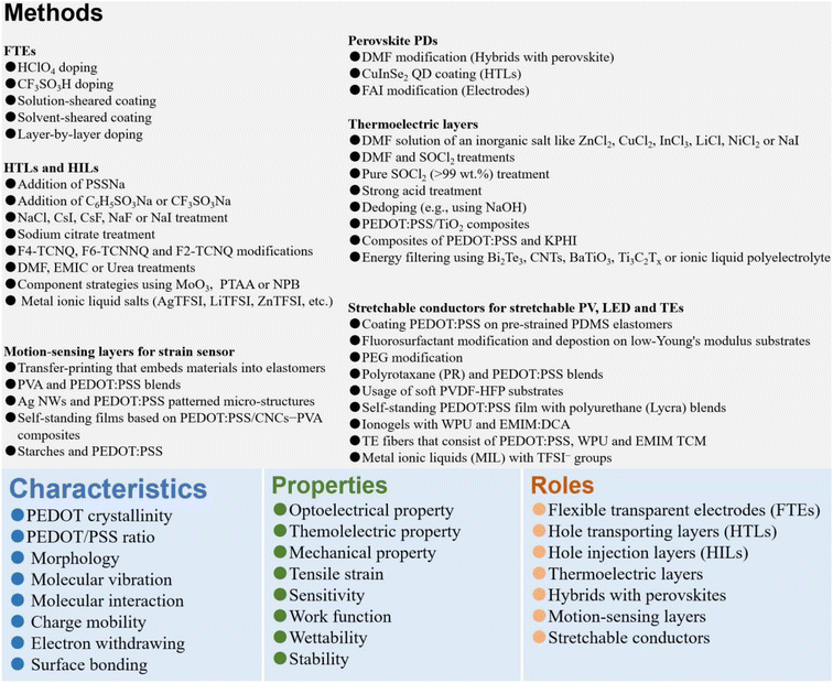
In the review, we first present the fundamental basis on the optoelectrical-, thermoelectric-, mechanical- and wettability-properties, work function, stability as well as charge-transfer underlying mechanisms of the PEDOT:PSS materials. Then, it indeed provides a broad overview of the significant breakthroughs and most cutting-edge progresses on the modern electronics including OSCs, PSCs, PPDs, TEs, LEDs, strain sensors, and flexible and stretchable devices (Fig. 1). According to the category of each device and the key role of PEDOT:PSS which plays in each device, the sections are divided briefly into five parts: (i) cutting-edge fabrication approaches of the PEDOT:PSS electrodes used in ITO-free and flexible OSCs, (ii) modification methods of the PEDOT:PSS HTLs along with broad applications in inverted PSCs, (iii) three-type PEDOT:PSS films (i.e., hybrids, HTLs and FTEs) for halide perovskite photodetectors, (iv) strategies to raise thermoelectric properties of PEDOT:PSS and its components, and (v) means to prepare conductive, stretchable and motion-sensitive PEDOT:PSS conductors for these stretchable electronics involving strain sensors, stretchable optoelectronics and thermoelectrics. All the methods to regulate the PEDOT:PSS properties are systematically summarized, directly linking them to the underlying mechanisms of the performance enhancements of the modern electronics. Finally, challenges, outlooks and suggestions on both developments of emergent PEDOT:PSS materials and as-integrated modern electronics are illustrated at the end of the review.
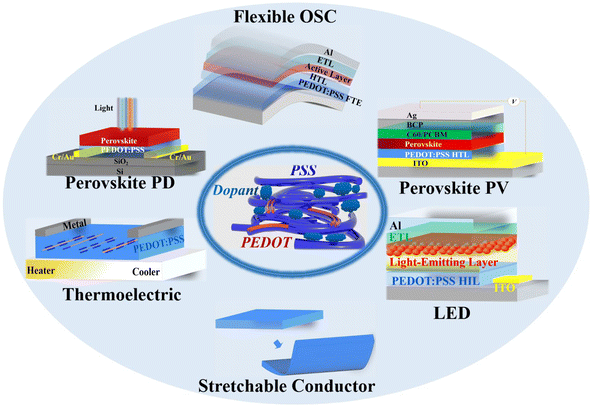 | ||
| Fig. 1 Schematic diagram of PEDOT:PSS applications in various optoelectronic and thermoelectric devices discussed in the review. | ||
2. Fundamental considerations for PEDOT:PSS electrodes in OSCs
Indium tin oxide (ITO)-free and flexible OSCs have stimulated tremendous attentions during the past decade. The flexible OSCs are commonly composed of an active layer sandwiched between a transparent electrode coated with a HTL and a metal negative electrode coated with a low-work-function ETL. PEDOT:PSS is one of the most representative FTEs owing to its good conductivity, high optical transmittance, superior flexibility, high uniformity, and low roughness. Since such highly conductive PEDOT:PSS transparent electrodes were attained through using the 1.0 M sulfuric acid (H2SO4) treatment73 by Ouyang et al. in 2012, a tremendous effort had been devoted to the polymer electrode preparation and flexible OSC construction. On the basis of an optimal PEDOT:PSS FTE, the single-junction normal flexible OSCs based on binary active layers exhibited a record-high power conversion efficiency (PCE) of 16.61% reported by Fan et al. in 2021.94A crucial factor in FTE performances is an electrical property. The electrical property of a thin film is generally evaluated by the sheet resistance (Rsh) and σ using a van der Pauw four-point probe technique, Rsh = πR/ln![[thin space (1/6-em)]](https://www.rsc.org/images/entities/char_2009.gif) 2, σ = Rsh/L, where R is the voltage between AB contacts to CD contacts (A, B, C and D are the four points of a square); σ is electrical conductivity; and L is the film thickness. In order to achieve a high σ, PEDOT crystallization, phase-segregated morphology and PEDOT/PSS ratios in matrices should be considered together with respect to the electrode preparation. The PEDOT crystallization is mostly determined by a structural conformation, which means a high electrical conductivity that mostly arises from an evolution of PEDOTs from benzoid structures to quinoid structures.119–121 A favorable phase-segregated morphology is induced by a weak coulombic attraction between PEDOT and PSS. While a low PEDOT/PSS ratio in the polymer matrices rather than only upon the surfaces demonstrates a lower sulfonate component, and it results in a high electrical conductivity because PSS is an insulating component.
2, σ = Rsh/L, where R is the voltage between AB contacts to CD contacts (A, B, C and D are the four points of a square); σ is electrical conductivity; and L is the film thickness. In order to achieve a high σ, PEDOT crystallization, phase-segregated morphology and PEDOT/PSS ratios in matrices should be considered together with respect to the electrode preparation. The PEDOT crystallization is mostly determined by a structural conformation, which means a high electrical conductivity that mostly arises from an evolution of PEDOTs from benzoid structures to quinoid structures.119–121 A favorable phase-segregated morphology is induced by a weak coulombic attraction between PEDOT and PSS. While a low PEDOT/PSS ratio in the polymer matrices rather than only upon the surfaces demonstrates a lower sulfonate component, and it results in a high electrical conductivity because PSS is an insulating component.
In this section, we focus on the cutting-edge doping treatments and unique processing technologies that substantially raise the conductivity, work function and wettability of the PEDOT:PSS FTEs. Progresses on ITO-free flexible OSCs are highlighted briefly, and suggestions are provided for the continued developments of both CP electrodes and flexible OSCs.
2.1. Secondary doping with HClO4 and CF3SO3H
In 2020, perchloric acid (HClO4) treatments are proposed for the first time by Fan et al. to chemically dope the PEDOT:PSS (Clevios™ PH1000) thin films as a FTE.99 As the strongest inorganic acid with ultrahigh acidity (pKa: −10) over those of H2SO4 (pKa: −3.0) and methanesulfonic acid (CH3SO3H, pKa: −1.9), the HClO4 treatments can provide a strong protonation of hydrogen ions (H+) to insulating PSS chains, thereby resulting in a high electrical conductivity. This optimal 0.1 M HClO4 treatment endowed the PEDOT:PSS electrodes with ≈32 Ω sq−1 sheet resistance, 90.4% transmittance at λ = 550 nm, and a better wettability towards the HTL droplet. The high wettability was due to a sulfonate-rich hydrophilic component on the electrode surfaces and a unique spray-coating of HClO4 ultrathin layers that bonded between the PEDOT:PSS electrodes and PEDOT:PSS (Clevios™ P VP AI 4083) HTLs. Consequently, it led to a small contacting angle (θ) of only 17° for an intimate interface contact. Besides, the HClO4 molecules induced a high work function (estimated value: 5.39 eV) for the PEDOT:PSS films via a polarization effect, owing to the polar chlorine–oxygen bonds of HClO4 with uncoupled charge centers. Therefore, a small potential barrier was induced at the interfaces through minimizing the energy level mismatch among the FTEs, HTLs and electron donors of active layers. As a result, the fully solution-processed flexible OSCs exhibited a 16.41% efficiency on the basis of a binary active layer of PM6:Y6 (Fig. 2a).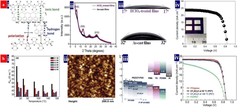 | ||
| Fig. 2 (a) (i) Inter-molecular interactions among PEDOT, PSS and HClO4; (ii) XRD spectra of the pristine and HClO4-treated films; (iii) wettability of the droplets (P VP AI 4083) on the pristine and 0.1 M HClO4-treated electrodes; and (iv) J–V characteristics of flexible OSCs with the PEDOT:PSS electrodes (active area: 0.3 cm2). Reproduced with permission.99 Copyright 2020, Royal Society of Chemistry. (b) (i) Sheet resistances of the PEDOT:PSS electrodes; (ii) morphology of PEDOT:PSS nanoparticles; (iii) energy levels of the device components; and (iv) J–V characteristics of flexible OSCs with PEDOT:PSS and ITO electrodes (active area: 0.04 cm2), and the rigid OSCs fabricated on ITO/glass substrates. Reproduced with permission.94 Copyright 2021, Springer Nature. | ||
In 2021, Fan et al. proposed a low-temperature (50 °C) and low-concentration (0.8 M) trifluoromethanesulfonic acid (CF3SO3H) treatment for constructing a fully solution-processed flexible OSC (Fig. 2b).94 CF3SO3H is a super acid with an ultrahigh acidity (pKa: −15) and it provides a strong protonation of H+ into PSS for high conductivity and better morphology. Owing to a polarization of polar carbon–fluorine (C–F) covalent bonds of CF3SO3H with uncoupled charge centers, the PEDOT:PSS films had a raised work function of up to 4.99 eV. The 0.8 M CF3SO3H treatment at 50 °C induced a low sheet resistance of ≈35 Ω sq−1, a transmittance of 87.5% at λ = 550 nm, a high work function of 4.99 eV and a superior hydrophilicity with θ of 23.5°. The optimized flexible OSCs exhibited the highest PCE of 16.61% (Fig. 2b). To the best of our knowledge, 16.61% is the highest PCE for single-junction ITO-free normal flexible OSCs with binary active layers reported thus far. Notably, both HClO4 and CF3SO3H treatments are indeed gentle and effective, consequently, the photovoltaic cells showed a high flexibility and a good thermal stability in a 200 hours thermal processing at 85 °C, i.e., a decrease by 9.1% in PCE in the thermal stability test. These optimal acid recipes open a methodology to invent high-performance fully solution-processed flexible OSCs based on strong acid and super acid-treated PEDOT:PSS FTEs. Table 2 summarizes the photovoltaic characteristics of the ITO-free flexible OSCs based on PEDOT:PSS electrodes and metal electrodes reported recently.
| Device structure | FTE | V OC (V) | J SC (mA cm−2) | FF | PCE | Retained (PCE) | Flexing test | Ref. | Year |
|---|---|---|---|---|---|---|---|---|---|
| PI/FTE/ZnO/PM6:N3:PC71BM/MoO3/Ag | Ag NW/AZO | 0.84 | 25.0 | 0.765 | 16.1% | 90% | 2 × 10³ cycling at r: 1.0 mm | 26 | 2020 |
| PET/FTE/AI4083/PM6:Y6/PNINN/Al | 0.1 M HClO4-treated PEDOT:PSS | 0.85 | 25.83 | 0.748 | 16.44% | — | — | 99 | 2020 |
| PET/FTE/AI4083/PM6:Y6/PNINN/Al | 0.8 M CF3SO3H-treated PEDOT:PSS | 0.86 | 25.83 | 0.748 | 16.61% | 90% | 103 cycling at r: 1 mm | 94 | 2021 |
| PET/FTE/ZnO/PM6:N3:PC71BM/MoO3/Ag | Em-Ag/Ag NW/AZO | 0.835 | 27.37 | 0.769 | 17.52% | 90% | 1.2 × 10³ cycling at r: 5 mm | 19 | 2022 |
| PET/FTE/ZnO/PM6:Y6/MoO3/Ag | Em-Ag/Ag NW/AZO | 0.833 | 25.55 | 0.738 | 15.71% | — | — | 19 | 2022 |
| PI/Ag/PCP-Li/AI4083/PM6:Y6:PC71BM/Bia-FIMG/FTE | 10 nm-thick Ag/TeO2 | 0.836 | 24.77 | 0.753 | 15.6% | 92% | 105 cycling at r: 4 mm | 28 | 2022 |
| Polyimide/FTE/AI4083/PM6:Y6/PNINO/Al | Cr | 0.84 | 25.8 | 0.702 | 15.2% | 90% | 103 cycling at r: 3.0 mm | 27 | 2020 |
| PET/FTE/ZnO/PM6:Y6/MoO3/Al | 72 wt% HClO4-treated PEDOT:PSS | 0.85 | 25.83 | 0.748 | 15.03% | — | — | 99 | 2022 |
2.2. Shearing technologies for thin film fabrication
A solution-shearing technology differs from conventional spin-coating ones and spray-coating ones, and it allows for a kinetic control over film morphology, composition and anisotropy via controlling the blading rate and temperatures of rigid substrates such as glass and silicon. Bao et al.3 reported a PEDOT:PSS electrode deposited by solution shearing at 130 °C. The PEDOT:PSS films were deposited at 65–85 °C on a temperature-controlled shearing stage; then, the films were placed on a hotplate at 130 °C, followed by dropping methanol on PEDOT:PSS tops. The solution-sheared PEDOT:PSS films were thermally annealed, cooled to room temperature, and rinsed with methanol. The specific control over deposition conditions allows for a tunable phase separation and a preferential PEDOT backbone alignment, thereby leading to a high conductivity. The solution-sheared electrodes showed more prominent well-defined fibers which were more elongated at a faster shearing speed of 3.0 mm s−1.A local segmental chain dynamic is affected by the viscosities of polar solvents,122 such as methanol, ethylene glycol (EG), and ethanol (EtOH). For example, the solvation of PSS is sensitive to the viscosities of the chosen polar solvents. Through adjusting the PSS solvation and structural rearrangement of PEDOT, a special shearing treatment using two solvents may induce PEDOT-rich domain ordering. On the principles, Bao et al.123 proposed a solvent-shearing technology using two solvents (methanol![[thin space (1/6-em)]](https://www.rsc.org/images/entities/char_2009.gif) :
:![[thin space (1/6-em)]](https://www.rsc.org/images/entities/char_2009.gif) EtOH = 1
EtOH = 1![[thin space (1/6-em)]](https://www.rsc.org/images/entities/char_2009.gif) :
:![[thin space (1/6-em)]](https://www.rsc.org/images/entities/char_2009.gif) 1) that resulted in a highly conductive PEDOT:PSS electrode. The solvent-sheared PEDOT:PSS films were prepared by solution shearing (90 °C and 1.5 mm s−1) and subsequently treated by the sheared solvents at 90 °C in ambient air. This shearing deposition induced a larger PEDOT/PSS ratio, which was attributed to the partial removals of PSS and the improved π–π stacking of the PEDOTs.
1) that resulted in a highly conductive PEDOT:PSS electrode. The solvent-sheared PEDOT:PSS films were prepared by solution shearing (90 °C and 1.5 mm s−1) and subsequently treated by the sheared solvents at 90 °C in ambient air. This shearing deposition induced a larger PEDOT/PSS ratio, which was attributed to the partial removals of PSS and the improved π–π stacking of the PEDOTs.
It is suggested that all of the parameters (thickness, uniformity, sheet resistance, and figure of merit) of each solvent-sheared film should be rigorously measured for precisely estimating the electrical conductivity. A main consideration is that the manufacturing processes of solvent-sheared films are rather complicated, at least involving solution-shearing, solvent-shearing, pre- and post-thermal annealing, and submerging in solvents. Film deposition quality, uniformity and thickness are sensitive to blading parameters, evaporation rates of solutions and solvents, ambient air conditions and storage times. In addition, on the basis of these PEDOT:PSS electrodes with superior conductivity, highly efficient lab-scale photovoltaic cells should be realized. The high photovoltaic performances of the photovoltaic cells not only can verify the reproducibility of the high-merit transparent electrodes, but also exemplify the great superiority of the most cutting-edge electrode preparation methods in terms of raising the charge extraction.
2.3. Layer-by-layer doping treatments
The electrical conductivity of the PEDOT:PSS films has been enhanced by the treatments of secondary polar solvents, strong acids, ionic liquids, etc.37–39,73,124,125 Among these methods, a strong acid treatment has emerged as one of the most effective methods to boost the film conductivity. One reason is the large removal of insulating PSS on the surfaces of the CP films. However, it hardly made a large removal of PSS from the whole PEDOT:PSS matrices, especially from the bottom half of the matrices. As such, the PEDOT:PSS transparent electrodes tend to exhibit a limited opto-electrical trade-off with a figure of merit (FoM) of <80.98A unique layer-by-layer (LBL) doping not only makes the large removals of PSS in the whole matrices rather than on the surfaces, but also induces a better phase-segregated morphology extruding large-domain aggregates. In 2020, Fan et al. proposed a unique LBL co-doping method that substantially improved the optical and electrical properties of the PEDOT:PSS electrodes coated on glass substrates.98 The PEDOT:PSS electrodes exhibited a record-high FoM of ≈100, which was due to (i) the effective doping of the PEDOT:PSS matrices for a high hole concentration (7.25 × 1021 cm−3) and hole mobility (3.62 cm2 V−1 s−1), (ii) a large removal of the insulating sulfonate components in matrices, and (iii) a refined phase-separated morphology without large-domain aggregates. On the basis of the LBL-treated PEDOT:PSS electrodes, a vacuum-free, all-solution and all-air processed OSC yielded a high PCE of 11.12%. To clearly describe the morphological evolution and structural rearrangement of the electrodes, the schematic diagrams of the models were illustrated (Fig. 3a). It explains why the LBL-treated CP electrodes have the outstanding optoelectrical properties over the conventional ones with secondary polar solvent or strong acid treatments. Generally, with the conventional strong acid treatments, the films which consist of small aggregates have many refined PEDOT-rich nanofibrils on the top half. An achievement of ordered stacking of PEDOT could be induced by the strong acid treatments.125 After the unique LBL doping treatment, more PEDOT-rich nanofibrils are induced from the coiled deformations to the linear/extended-coil deformations. Besides, it largely reduced the insulating PSS components in the whole matrices including the front and rear sides (Fig. 3b). As a result, the CP electrodes not only yielded the record-high FoM of up to 100 along with σ of 4200 S cm−1, but they also showed an enhanced electrical stability and a much better electrochemical stability under a cyclic voltammetry testing in anhydrous dichloromethane while using 0.1 M Bu4NPF6 as an electrolyte.
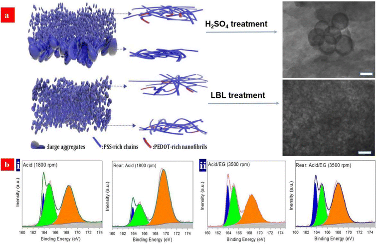 | ||
| Fig. 3 (a) Schematic diagram of morphology of the acid-treated films and LBL-treated films, respectively. (b) Fitted S 2p XPS Spectra of the front and rear sides of the PEDOT:PSS films: (i) the acid-treated PEDOT:PSS films at spin coating of 1800 rpm; and (ii) the acid and EG co-treated PEDOT:PSS films at spin coating of 3500 rpm. Reproduced with permission.98 Copyright 2020, Wiley-VCH. | ||
The limited electrical conductivity of PEDOT:PSS FTEs is a remaining major challenge of the PEDOT:PSS FTEs at present. Although many approaches dramatically improve the conductivity over 4000 S cm−1, such a film conductivity still lags far behind the estimated values (13![[thin space (1/6-em)]](https://www.rsc.org/images/entities/char_2009.gif) 000 (ref. 121) and 16
000 (ref. 121) and 16![[thin space (1/6-em)]](https://www.rsc.org/images/entities/char_2009.gif) 600 (ref. 91) S cm−1) of the commercial ITO electrodes sputtered on glass substrates; furthermore, most of strong acid treatments reported previously were corrosive to underlying metallic nanowires and grids. Therefore, novel recipes for strong acid treatments and other acid-free doping treatments should be developed to further improve the CP conductivity and such methods need to be compatible with most of underlying thermoplastic substrates and the component transparent electrodes that consist of the CPs and metal nanowires or grids. The improvement of the underlying mechanisms of both stability and flexibility enhancements for the photovoltaic cells should be sought in the future.
600 (ref. 91) S cm−1) of the commercial ITO electrodes sputtered on glass substrates; furthermore, most of strong acid treatments reported previously were corrosive to underlying metallic nanowires and grids. Therefore, novel recipes for strong acid treatments and other acid-free doping treatments should be developed to further improve the CP conductivity and such methods need to be compatible with most of underlying thermoplastic substrates and the component transparent electrodes that consist of the CPs and metal nanowires or grids. The improvement of the underlying mechanisms of both stability and flexibility enhancements for the photovoltaic cells should be sought in the future.
3. Fundamental considerations for PEDOT:PSS HTLs in PSCs
Perovskite solar cells have been on the forefronts of novel photovoltaics over the past decade.126–129 The perovskites are a category of compounds with the structure of ABX3, where A is organic cations including CH3NH3+ (MA+) and HC(NH2)2+ (FA+), B is Pb2+ or Sn2+, and X is a halogen anion such as I−, Br−, and Cl−. The perovskite layers exhibit excellent optoelectronic properties such as a wide visible light absorption spectrum, high absorption coefficient, high charge carrier mobility, low exciton binding energy, high defect tolerance, and long electron and hole diffusion length. The current champion of the PSCs exhibited an inspiring PCE as high as 26.08% (certified 25.73%) under standard illumination.127 The single-junction PSCs have two types of structures: conventional ones and inverted ones. The conventional one involves a bottom ETL of metal-oxides such as titanium dioxide (TiO2) and tin dioxide (SnO2) coated onto ITO films. The inverted one involves a bottom HTL coated on ITO films, such as PEDOT:PSS, polybis(4-phenyl)(2,4,6-trimethylphenyl)amine (PTAA), and poly(3-(4-methylamincarboxylbutyl)thiophene) (P3CT-N). The inverted PSC devices have the striking advantage of negligible device hysteresis; meanwhile, the harsh sintering treatments at high temperatures can be extruded in the device fabrication.In the inverted PSCs, a HTL should have a high work function, good wettability and suitable electrical conductivity as minimum requirements. The work function of the HTLs can be confirmed by ultraviolet photoelectron spectra (UPS), φ = hν + Ecutoff − EFermi, where Ecutoff and EFermi is the low kinetic energy cutoff and Fermi level, respectively. A hydrophilic PEDOT:PSS HTL facilitates the target formation of perovskite crystallinity consisting of large grains. Owing to an adjustable electrical conductivity, high work function and high solubility, the PEDOT:PSS (Clevios™ P VP AI 4083) products are the promising HTL and HIL materials used to fabricate the currently existing photovoltaics and LEDs, respectively.
A modified PEDOT:PSS film can have φ of 4.7–5.3 eV. A high φ of the HTLs allows for a formation of ohmic contacts and it is favorable for hole transport from the perovskite layers to the transparent electrodes. The work function of the CP HTLs depends on the PEDOT:sulfonate ratios, electron withdrawing groups (e.g., –Cl, –F, –Br, –SO3−) of dopants, PEDOT crystallinity, etc. The section provides an overview of significant progresses on both modified PEDOT:PSS HTLs and inverted PSCs. Approaches to tune the properties of the PEDOT:PSS HTLs are clearly introduced. The underlying mechanisms for enhancement of device-efficiency and some related suggestions are illustrated as well.
3.1. Sulfonate treatments
Typically, exciton quenching occurs at the interfaces between PEDOT:PSS (Clevios™ P VP AI 4083) HTLs and halide perovskite layers, and thus, it delays the device efficiency via a radiative recombination of charge carriers. Ding's group reported a PEDOT:PSS (P VP AI 4083) HTL that was treated by the polymer electrolyte of sodium polystyrene sulfonate (PSSNa) to improve its work function.130 Compared to that of the pristine one, the work function of the PSSNa-treated PEDOT:PSS HTL was higher by 0.3 eV, which led to an open circuit voltage (VOC) of 1.11 V and a PCE of 15.56% (Fig. 4a). Subsequently, Zang's group employed sodium benzenesulfonate (C6H5SO3Na) to modify the PEDOT:PSS (P VP AI 4083) HTLs.131 It led to a smooth surface of the PEDOT:PSS HTLs as well as a better energy level alignment with the perovskite crystalline layers. Besides, the C6H5SO3Na treatment raised the hole extraction capacity and it suppressed charge recombination, thereby increasing the grain size and crystallinity of the MA0.8FA0.2PbI3−xClx perovskite films (Fig. 4b). Consequently, the PCE and VOC of the inverted PSCs were improved to 19.41% and 1.08 V, respectively, which are higher than those (PCE: 18.07% and VOC: 1.04 V) of the control inverted PSCs without the C6H5SO3Na treatment. It should be also mentioned that sulfonate treatments caused rich sulfonate components in PEDOT:PSS matrices, presumably resulting in a stability issue of the PSCs due to the strong intrinsic hygroscopicity of the sulfonate components. Therefore, a small doping content of the sulfonates is critical for an adaptation of the inverted PSCs based on the PEDOT:PSS HTLs with promoted stability against humidity and ultraviolet lights. Besides, with respect to the sulfonate treatments, other concentrations and small gradients especially between 3 and 15 mg mL−1 should be used for the PSC device optimization. We envision that a similar treatment using the sulfonates (e.g., CF3SO3Na) involving electron withdrawing groups may further raise the work function and morphology of the PEDOT:PSS HTLs for a better photovoltaic cell.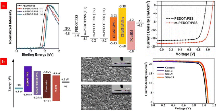 | ||
Fig. 4 (a) UPS of PEDOT:PSS and m-PEDOT:PSS films; energy level diagram of the PSCs; and J–V curves of the PSCs with PEDOT:PSS or m-PEDOT:PSS (1![[thin space (1/6-em)]](https://www.rsc.org/images/entities/char_2009.gif) : :![[thin space (1/6-em)]](https://www.rsc.org/images/entities/char_2009.gif) 2) as the HTL. Reproduced with permission.130 Copyright 2017, Wiley-VCH. (b) Energy level diagram of devices; SEM of perovskite active layers deposited on PEDOT:PSS with C6H5SO3Na (9 mg mL−1); and J–V curves of the devices with the PEDOT:PSS HTLs with C6H5SO3Na (0, 3, 9 and 15 mg mL−1). Reproduced with permission.131 Copyright 2021, Wiley-VCH. 2) as the HTL. Reproduced with permission.130 Copyright 2017, Wiley-VCH. (b) Energy level diagram of devices; SEM of perovskite active layers deposited on PEDOT:PSS with C6H5SO3Na (9 mg mL−1); and J–V curves of the devices with the PEDOT:PSS HTLs with C6H5SO3Na (0, 3, 9 and 15 mg mL−1). Reproduced with permission.131 Copyright 2021, Wiley-VCH. | ||
3.2. Sodium- and cesium salt treatments
To illustrate the significant effect of the PEDOT:PSS HTL modifications on PSC performances, Hu et al.132 reported an effective and simple treatment by adding 5 mg mL−1 sodium chloride (NaCl) into the PEDOT:PSS (P VP AI 4083) aqueous solutions. The PCE of the inverted PSCs based on the NaCl-doped HTLs was much higher than that of the control solar cells with the pristine PEDOT:PSS HTLs (Fig. 5a). Note that the best PSCs delivered a PCE of up to ≈18.2% with a fill factor (FF) as high as 0.800. The high PCE is attributed to two factors as follows: (i) a raised electrical conductivity and hole extraction of the NaCl-treated PEDOT:PSS HTLs and (ii) a preferred orientation along the (001) direction of the uniform perovskite films on the NaCl-treated PEDOT:PSS HTLs. Subsequently, Jiang et al.133 developed a similar strategy through doping the PEDOT:PSS with cesium iodide (CsI). The CsI treatment reduced the voltage loss and it enabled a high-efficiency inverted PSC based on the PEDOT:PSS HTLs. CsI materials reacted with the PbI2 materials. This chemical reaction not only led to a formation of CsPbI3 but also induced a better interfacial contact for charge-carrier transport. The CsI-treated PEDOT:PSS HTLs enabled a better PSC with a non-radiative voltage loss of 0.287 V, which was superior to the control device with a non-radiative voltage loss of 0.375 V. The best inverted PSCs exhibited a small voltage loss, a high PCE of up to 20.22%, a VOC of 1.084 V and almost no hysteresis; whereas the control ones with the pristine PEDOT:PSS HTLs just delivered a PCE of 16.57% (Fig. 5b). In the future, the effective treatments using CsF, NaF and NaI and combined treatments using the salts and bases can be developed to make the PEDOT:PSS HTLs. Through optimizing the doping concentrations, doping temperatures and processing times, both high-φ PEDOT:PSS HTLs and high-quality perovskite layers have a high probability of achievement for exciton dissociation and charge-carrier transport, thereby leading to an improved PCE of the inverted PSCs.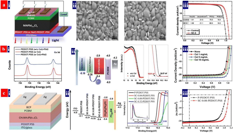 | ||
| Fig. 5 (a) (i) PSC architecture; (ii) SEM images of perovskite films deposited on pristine PEDOT:PSS and NaCl-PEDOT:PSS; and (iii) J–V curves of the PSCs with pristine or NaCl-doped PEDOT:PSS. Reproduced with permission.132 Copyright 2017, American Chemical Society. (b) (i) Cs 3d XPS binding energy; (ii) energy level diagram of the PSCs and UPS binding energy of PEDOT:PSS films with and without CsI; and (iii) J–V curves of inverted PSCs processed with PEDOT:PSS containing CsI in different concentrations. Reproduced with permission.133 Copyright 2019, Royal Society of Chemistry. (c) (i) PSC architecture; (ii) energy level diagram of the PSCs and UPS binding energy of PEDOT:PSS films; and (iii) J–V curves of the inverted PSCs. Reproduced with permission.134 Copyright 2019, American Chemical Society. | ||
Recently, Song's group added sodium citrate into the PEDOT:PSS aqueous solutions for PEDOT:PSS HTL preparation.134 The sodium citrate treatment increased the work function of the HTLs and it made the valence band of perovskite absorbers compatible with the HTLs; besides, upon the sodium citrate treatments, the grain sizes of the perovskite crystals became larger when deposited on the PEDOT:PSS HTLs; meanwhile the perovskite layers were more uniform. On the basis of the sodium citrate-treated PEDOT:PSS HTLs, the PCE of the CH3NH3PbI3(Cl)-based PSCs largely increased from 15.05% to 18.39%. The PCE enhancement originated from a simultaneous increase in VOC, short-circuit current density (JSC) and FF (Fig. 5c).
3.3. F4-TCNQ treatment
A surface-modification strategy has emerged to raise the work function and electrical conductivity of the PEDOT:PSS HTLs. For example, Liu et al.135 investigated the effects of a p-type dopant 2,3,5,6-tetrafluoro-7,7,8,8-tetracyanoquinodimethane (F4-TCNQ) on the optoelectrical properties of PEDOT:PSS HTLs and the photovoltaic parameters of inverted PSCs. After adding 0.30 wt% F4-TCNQ into the PEDOT:PSS aqueous solutions, the PEDOT:PSS HTL showed a lower highest occupied molecular orbital (HOMO) level for a high work function of 5.24 eV, and the film exhibited an enhanced conductivity of 0.136 S cm−1. Notably, the favorable energy level alignment and the enhanced conductivity of the F4-TCNQ-doped films allow an efficient carrier transport from the perovskite layer to the HTL. As a result, the inverted PSCs with the 0.30 wt% F4-TCNQ-doped PEDOT:PSS HTL yielded a PCE of 17.22%, which was much higher than that (13.30%) of the control PSCs (Fig. 6).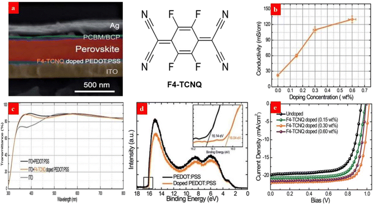 | ||
| Fig. 6 (a) Cross-sectional SEM of each layer with the chemical structures of F4-TCNQ. (b) Dependence of the film conductivity on the doping concentration. (c) Film transparencies. (d) UPS of the PEDOT:PSS films. (e) J–V curves of the PSCs with the PEDOT:PSS HTLs. Reproduced with permission.135 Copyright 2017, Royal Society of Chemistry. | ||
Owing to the strong electron withdrawing capability of the fluorine atoms of F4-TCNQ, it is captured from the PEDOT materials to increase the number of molecular holes of the polymer matrices. We advise that other p-type molecules involving fluorine atoms, such as 2,2′-(perfluoronaphthalene-2,6-diylidene)dimalononitrile (F6-TCNNQ) and 2,5-tetrafluoro-7,7,8,8-tetracyanoquinodimethane (F2-TCNQ), can be used to modify the PEDOT:PSS films for an efficient charge transfer and a high device efficiency in the future. Besides, it is suggested that solution-processed metal oxide HTLs such as NiOx and MoO3 have a potential to improve the device efficiency and stability through using the similar doping treatments mentioned above.
3.4. DMF, EMIC and urea treatments
Dimethylformamide (DMF) treatments can improve the electrical conductivity of the PEDOT:PSS HTLs via reduction of the Coulomb interactions between PEDOT and PSS. Chen et al.136 employed the DMF-treated PEDOT:PSS HTLs and polymethyl methacrylate (PMMA)-modified PCBM ETLs to establish a charge-carrier balance in the p-i-n PSCs. The electrical conductivity (≈10−1 S cm−1) of the DMF-treated PEDOT:PSS thin films were higher than that (≈10−3 S cm−1) of as-cast thin films. The higher conductivity of the PEDOT:PSS films facilitated an interfacial contact between the perovskite layers and PEDOT:PSS HTLs. As shown in Fig. 7, the PEDOT crystal sizes varied from 1.30 nm (as-cast ones) to 2.44 nm (DMF-treated ones), and the large crystal size could be attributed to a diffusion of the organic solvents into PEDOT:PSS matrices and a low π–π stacking distance of PEDOTs.136,137 The resultant PSCs yielded a high PCE of 18.72%. An inspiring result is that the VOC had a slower photovoltage decay than the reference, suggesting a lower charge-carrier-recombination rate and more balanced charge-carrier transport.137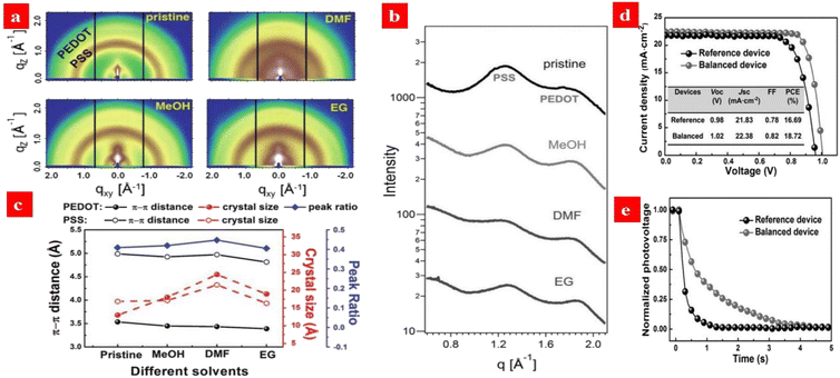 | ||
| Fig. 7 (a) 2D GIWAXS measurements of PEDOT:PSS films treated by different solvents. (b) Sector integrals of the 2D GIWAXS data. (c) An overview of the crystallite sizes, stacking distances, and the PEDOT ratios in PEDOT:PSS films treated by different solvents. (d) J–V curves of the PSCs. e Open-circuit photovoltage-decay measurements. Reproduced with permission.136 Copyright 2016, Wiley-VCH. | ||
In terms of ionic liquid (IL) doping treatments, Zhou et al.138 developed a novel synergistic strategy that uses 1.5 wt% EMIC (1-ethyl-3-methylimidazolium chloride) ionic liquid to modify the PEDOT:PSS HTLs. It enables a HTL with an improved electrical conductivity of up to 200 S cm−1, a relatively low work function of 5.18 eV and a smooth surface. This doping treatment helps to extent the carrier recombination life time and it reduces the charge trap density of the perovskites. As a result, the champion photovoltaic cells showed 20.06% PCE without hysteresis (Fig. 8).
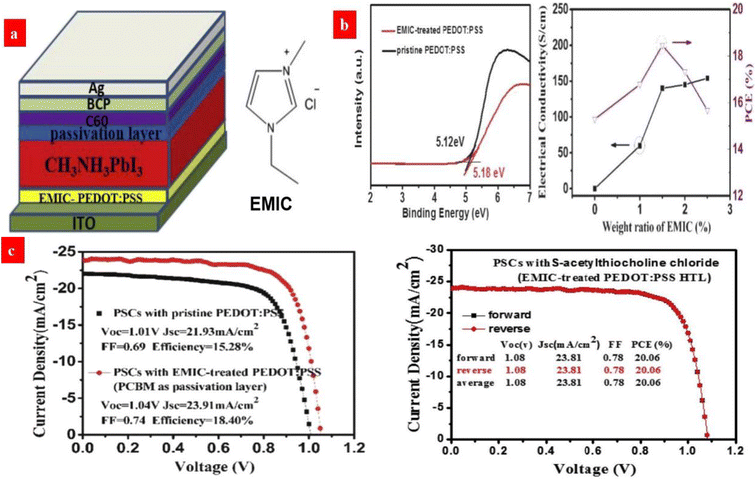 | ||
| Fig. 8 (a) Configuration of an inverted PSC device and the molecular structure of EMIC. (b) UPS spectra of pristine and EMIC-treated PEDOT:PSS films, and electrical conductivities of PEDOT:PSS HTL. (c) J–V curves of the PCBM-based PSCs with the pristine and EMIC-treated PEDOT:PSS HTL, and the best PSCs with both EMIC-PEDOT:PSS HTL and S-acetylthiocholine chloride passivation layer. Reproduced with permission.138 Copyright 2019, Elsevier. | ||
In order to improve the conductivity as well as work function of the PEDOT:PSS HTLs, Elbohy et al.139 demonstrated a urea treatment that effectively tuned the phase-separated morphology of the PEDOT:PSS HTLs. After the urea treatment, the coulombic interaction between the PEDOT and PSS segments was dramatically decreased and it allowed for a better phase separation between the conductive PEDOT and the insulating PSS regions. As a result, the 5 wt% urea-treated PEDOT:PSS films had a nanofibril-like morphology; and the films showed an electrical conductivity of 12.75 S cm−1. In contrast, the electrical conductivity was only 0.20 S cm−1 for the pristine films. The enhanced conductivity was mainly induced by the better phase-separated morphology with the rich nanofibrils. Urea also inhibited the counter-ion exchange interaction between the PEDOT:PSS and perovskites by transforming PSS-H into PSS-NH4 for a better PSC. The device PCE was increased from ≈14.4% to ≈18.8%.
3.5. Component strategies
It is promising to invent an efficient inverted PSC via employing a component HTL that consists of PEDOT:PSS (P VP AI 4083), metal oxides and organic materials (e.g., PTAA).140,141 For example, Choi et al.140 reported a flexible inverted PSC using PEDOT:PSS (P VP AI 4083) and MoO3 as a component HTL. The 2.0 nm-thick thin layers of MoO3 enabled an efficient hole doping into graphene electrodes. The PEDOT:PSS and MoO3 components had the suitable energy levels for effective hole transport. The resultant PSCs showed a PCE of ≈16.8% without visible hysteresis, which was slightly lower than that (≈17.3%) of the control PSCs fabricated on ITO/glass. Next, Zang's group142 proposed a facile passivation approach that employed an ultrathin PTAA layer to passivate the interfacial and grain boundary defects (Fig. 9). This PTAA is sandwiched between the perovskites and the HTLs to suppress interfacial recombination and accelerate hole transfer. An energy band alignment was realized by introducing this ultrathin PTAA layer. As a result, the inverted PSCs yielded a considerably high PCE of 19.04% with FF of 82.59% and JSC of 21.38 mA cm−2. In the future, the methodologies of HTLs fabricated from composites of PEDOT:PSS deserve further rigorous pursuit towards greater improvement of for an energy band alignment and an intimate contact at interfaces. The energy band alignment among transparent electrodes, HTLs and perovskites can suppress the interfacial recombination and accelerate the hole transfer, resulting in a high PCE of the inverted PSCs.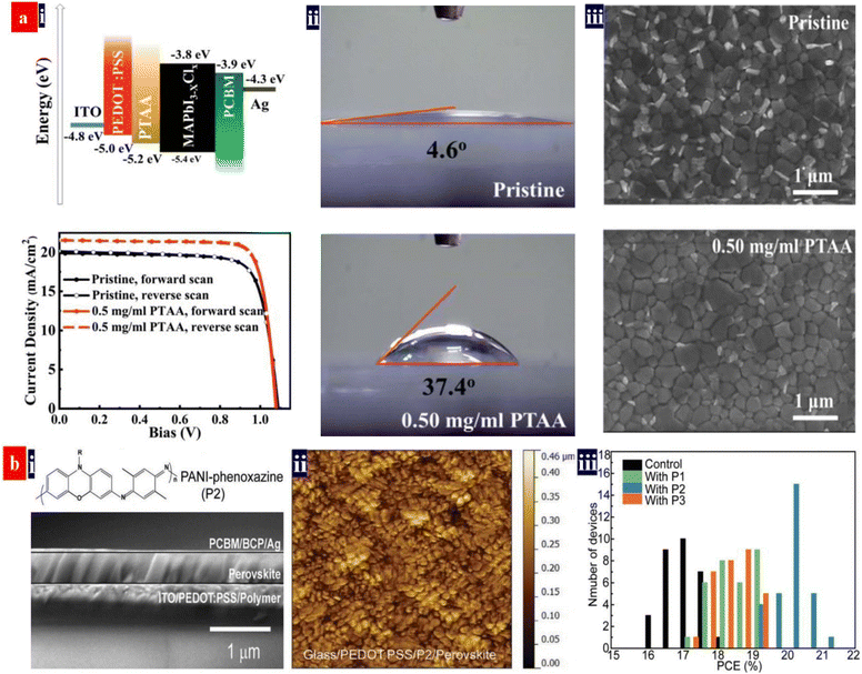 | ||
| Fig. 9 (a) (i) Energy level diagram, and the typical J–V curves of the inverted PSCs, (ii) contact angles of the PEDOT:PSS HTLs modified by PTAA: 0 mg mL−1 (top) and 0.50 mg mL−1 (bottom) and (iii) SEM images of the perovskite films. Reproduced with permission.142 Copyright 2019, Royal Society of Chemistry. (b) (i) the cross-sectional SEM image of the MAPbI3 inverted PSCs with the P2, (ii) AFM images of perovskite films on various PEDOT:PSS substrates, and (iii) the PCE distribution of the inverted PSCs. Reproduced with permission.4 Copyright 2022, Wiley-VCH. | ||
Otherwise, Ma et al.143 introduced a triphenylamine-based small molecule, N,N′-bis-(1-naphthalenyl)-N,N′-bis-phenyl-(1,1-biphenyl)-4,4′-diamine (NPB), into the inverted PSCs as the multifunctional buffer layer (Fig. 10). The NPB buffer layer inserted not only restrains a formation of pin-holes and defects of the perovskites, but also it reduces the energy level mismatch between the perovskites and PEDOT:PSS HTLs. As a result, the devices showed a reduced trap density and a prolonged carrier lifetime, which led to an increase of the PCE from 15.4% to 18.4% without hysteresis. It should be mentioned that the inverted PSCs with the NPB/PEDOT:PSS HTLs possessed a relatively long-term stability under ambient air and under UV-light irradiation, which was attributed to the superior moisture and UV-light resistance of the NPB layers that shielded the PEDOT:PSS bottom layers.
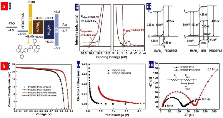 | ||
| Fig. 10 (a) (i) Energy level diagram and molecular structure of NPB; (ii) UPS of the PEDOT:PSS HTLs; and (iii) energy level alignment diagrams at PEDOT:PSS/MAPbI3 and PEDOT:PSS/NPB/MAPbI3 interfaces. (b) (i) J–V curves of the inverted PSCs; (ii) extracted lifetime of the injected carriers versus photovoltage; and (iii) electrical impedance spectroscopy spectra. Reproduced with permission.143 Copyright 2022, Elsevier. | ||
These aforementioned modification treatments and component strategies significantly improve the PCEs of the inverted PSCs. Table 3 summarizes the photovoltaic characteristics of the inverted PSCs based on the PEDOT:PSS HTLs reported recently. In the future, a higher charge-carrier mobility and a better balance between hole mobility (μh) and electron mobility (μe) are highly derisible for the development of highly efficient and stable inverted PSCs; and we envision that the high-performance photovoltaic cells will be realized by the pathways, e.g., HTL and ETL co-modifications, a perovskite passivation, an insertion of insulating ultrathin layers (e.g., PMMA and Al2O3), etc. Finally, an ideal PEDOT:PSS HTL needs to stabilize its electronic structure, electrical conductivity, work function and morphology, which are indeed very critical to the operation stability of the photovoltaic cells as well as an intimate contact with the perovskite layers on tops.
| Device structure | Method and recipe | φ (eV) | σ (S cm−1) | V OC (V) | J SC (mA cm−2) | FF | PCE | Ref. | Year |
|---|---|---|---|---|---|---|---|---|---|
| FTO/PEDOT:PSS/P2/MAPbI3/PC61BM/BCP/Ag | Deposition of P2 on PEDOT:PSS | 5.37 | — | 1.13 | 23.56 | 0.791 | 21.06% | 4 | 2022 |
| ITO/PC-PEDOT/MAPbI3/PC61BM/BCP/Ag | 0.035 M potassium citrate treatment | 4.55 | — | 1.099 | 21.93 | 0.819 | 19.66% | 129 | 2021 |
| ITO/C6H5SO3Na-PEDOT:PSS/MA0.8FA0.2PbI3−xClx/PC61BM/Ag | 9 mg mL−1 C6H5SO3Na treatment | 5.25 | — | 1.08 | 21.52 | 0.801 | 19.41% | 131 | 2021 |
| ITO/PEDOT:PSS-WOx/MAPbI3/PC61BM/ZnO/Al | Deposition of WOx on PEDOT:PSS | — | — | 1.08 | 22.78 | 0.804 | 19.64% | 128 | 2020 |
| FTO/PEDOT:PSS/NPB/MAPbI3/PC61BM/BCP/Ag | 15 nm-thick BCP modification | 5.40 | — | 1.05 | 22.46 | 0.780 | 18.40% | 143 | 2020 |
| ITO/SC-PEDOT/CH3NH3PbI3(Cl)/PC61BM/BCP/Ag | 0.08 M sodium citrate treatment | 5.32 | — | 1.134 | 21.62 | 0.750 | 18.39% | 134 | 2019 |
| ITO/CsI-PEDOT:PSS/MAPbI3/PC61BM/Ag | 5 mg mL−1 CsI treatment | 5.26 | — | 1.08 | 22.59 | 0.83 | 20.22% | 133 | 2019 |
| ITO/urea-PEDOT:PSS/MAPbI3/PC61BM/Rhodamine/Ag | 0.5 wt% urea treatment | — | 12.75 | 1.03 | 22.57 | 0.809 | 18.80% | 139 | 2019 |
| ITO/PEDOT:PSS/MAPbI3/PC61BM/C60/BCP/Ag | 1.5 wt% EMIC treatment | 5.18 | 200 | 1.04 | 23.91 | 0.74 | 18.40% | 138 | 2019 |
| ITO/PEDOT:PSS/MAPbI3/S-acetylthiocholine chloride/C60/BCP/Ag | 1.5 wt% EMIC treatment | 5.18 | 200 | 1.08 | 23.81 | 0.78 | 20.06% | 138 | 2019 |
| ITO/F4-TCNQ-PEDOT:PSS/CH3NH3PbI3−xClx/PC61BM//BCP/Ag | 0.3 wt% F4-TCNQ modification | 5.18 | 0.11 | 1.02 | 21.73 | 0.77 | 17.22% | 135 | 2017 |
| ITO/DMF-PEDOT:PSS/MAPbI3/PC61BM/PMMA/BCP/Ag | DMF rinsing | — | — | 0.98 | 22.70 | 0.81 | 18.02% | 136 | 2016 |
| ITO/DMF-PEDOT:PSS/MAPbI3/PC61BM/BCP/Ag | DMF rinsing; 1.0 wt% PMMA modification | 5.12 | 10−1 | 1.02 | 22.38 | 0.82 | 18.72% | 136 | 2016 |
4. Perovskite photodetectors with PEDOT:PSS
Photodetectors probe various optical signals from background radiation and then convert them to various electrical signals. The devices have a promising application in high-speed optical communication and high-resolution imaging.144 Halide perovskite materials have received much research interest in photodetector fields, owing to their excellent optoelectronic properties of appropriate direct bandgaps, high light absorption coefficients and long carrier transport lengths.144–146 Halide perovskite photodetectors have three types: photoconductors, photodiodes and phototransistors.146–150 This section focuses on the perovskite-based photodetectors with the PEDOT:PSS thin films. It illustrates the key roles of the PEDOT:PSS on the device performances. Finally, suggestions are provided for potentially guiding the development of future photodetectors based on PEDOT:PSS.4.1. Phototransistors with Perovskite/PEDOT:PSS heterojunctions
Organolead halide perovskites suffer from low gains in comparison with phototransistors based on other functional materials. Moreover, a detectable wavelength region is limited by a bandgap issue of the perovskites. Yan's group demonstrated a broadband phototransistor with MAPbI3−xClx/PEDOT:PSS (Clevios™ PH500) heterojunctions.151 Under light illumination, excitons were generated in the MAPbI3−xClx matrices. Then, the holes diffused into the PEDOT:PSS layer because of an decreased energy; while the electrons accumulated in the MAPbI3−xClx films since the conduction band of the MAPbI3−xClx materials was lower than the lowest unoccupied molecular orbital (LUMO) level of the PEDOT:PSS materials. Most of the channel currents originate from the hole transport in the PEDOT:PSS thin layers. The currents across the perovskite layers are extremely small. It is supposed that the DMF from the perovskite solutions indeed improves the electrical conductivity of the PEDOT:PSS films, leading to a high hole mobility and an effective hole transport in PEDOT:PSS matrices. The PD devices showed a high responsivity (R) of 109 A W−1 and a specific detectivity (D*) of 1014 Jones in spectral response ranges of 350–1100 nm at 0.5 V operating bias. In such an innovative phototransistor, the photo-generated electrons are not necessarily mobile in the perovskite films. Thus, a high R in the near infrared (NIR) region could be achieved.The spectral response range of typical MAPbI3-based PDs is generally limited owing to the relatively wide optical bandgap. The perovskite materials with smaller optical bandgaps can be realized by the blends of halogen ions, the blends of Sn and Pb, Cs-doped FAPbI3, etc.145–157 It should be mentioned that the leads in the perovskite materials can potentially cause severe human health and environmental problems, hampering a practical application of the PDs. Yan's group demonstrated a photodetector with a tin-based perovskite/PEDOT:PSS (Clevios™ PH500) vertical heterojunction (Fig. 11).157 The FASnI3/PEDOT:PSS device showed a broadband photo-response from NIR to UV, a high responsivity of 2.6 × 10⁶ A W−1, gain of 4.7 × 10⁶ and specific detectivity of 3.2 × 10¹² Jones. The high responsivity was attributed to the long carrier lifetime and strong light absorption of the perovskites and the strong photo-gating effect. The photo-gating effect stemmed from the perovskite/PEDOT:PSS vertical heterojunction. In the future, through adjusting the LUMO or Fermi levels of the PEDOT:PSS thin films and raising the hole mobility, the perovskite PD performances could be potentially further enhanced due to a raised capability of charge separation and hole transport.
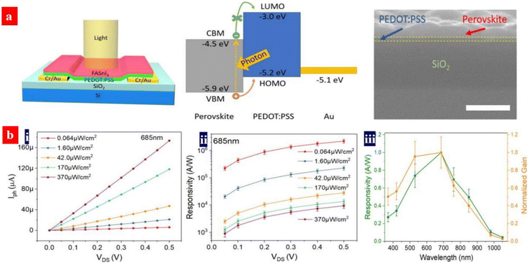 | ||
| Fig. 11 (a) Architecture structure of the PDs, energy band diagram, and cross-sectional SEM image of (a) FASnI3/PEDOT:PSS bilayer coated on SiO2/Si. Scale bar: 300 nm. (b) (i) Photo-current vs. drain voltage; (ii) average responsivity vs. drain voltage under various intensity of light. Wavelength: 685 nm; and (iii) normalized spectral responsivity and gain of the PD. Reproduced with permission.157 Copyright 2020, American Chemical Society. | ||
4.2. X-ray detectors with PEDOT:PSS HTLs
X-ray detectors have applications in the structural determinations of crystals, noninvasive imaging, security inspection, medical radiography, and nuclear power stations.158 Perovskites can detect the ultraviolet-visible-near infrared (UV-vis-NIR) photons and the high-energy X-rays and γ-rays. The heave atoms of Pb, I and Br dominate the high-energy photon absorption; then, the high-energy photons with a strong penetrating capability enable a carrier generation across the crystals. According to α ∝ Z4/E3, the atomic number (Z) determines the attenuation coefficient (α), where E is the photon energy. To ensure an efficient charge collection of the detector, it requires a large charge carrier mobility (μ) − charge carrier lifetime (τ) product, a high resistivity and a low charge trap density.159Heiss's group previously proposed a concept of applying MAPbI3 semiconductors for the X-rays detection.160 The MAPbI3 photoconductors with the PEDOT:PSS HTLs showed an almost ideal photo-response in the NIR to vis ranges, a fast response time and a high absorption cross-section for X-rays owing to the heavy Pb and I atoms. Notably, a high-quality MAPbBr3 layer was also deposited on hydrophobic PTAA instead of the PEDOT:PSS HTLs.161 Recently, the PEDOT:PSS HTLs were used to fabricate broadband photodetectors with a component active layer that consists of CH3NH3PbI3 and CuInSe2 quantum dots (CISe QDs) (Fig. 12a).162 The component active layer absorbs radiation, generates the electron–hole pairs, and then transports the holes from the perovskites and CISe QDs to the HTLs due to gradient energy alignment.162 The HOMO level of the PEDOT:PSS is slightly shallower than the valence band position of the CISe QDs, which is energetically favorable for holes transfer and extraction. The photodetector delivered a broadband response from the UV to the NIR. Notably, the perovskites showed an optical response from the UV to vis regions, while the CISe QDs provided a light response in the NIR regions. The best photodetector exhibited a responsivity of 193 mA W−1 at 580 nm and >20 mA W−1 in the NIR region of 800–1000 nm. The device had a D* of >7.0 × 10¹² Jones in the vis and 7.7 × 10¹¹ Jones in the NIR with a transient response time of 277 ns. In a previous literature,163 the CuInSe2 QDs and PEDOT:PSS emerged as a hybrid HTL of the perovskite photodetectors (Fig. 12b). The CuInSe2 QDs increased the HTL wettability for a better growth of perovskite crystals. Additionally, the QDs blocked the electron transfer from perovskites to PEDOT:PSS.163 The resultant devices with the CuInSe2 QDs and PEDOT:PSS hybrid HTLs showed a photoresponsivity of 240 mA W−1 at 580 nm and a maximum detectivity of 1.02 × 10¹³ Jones at 580 nm.
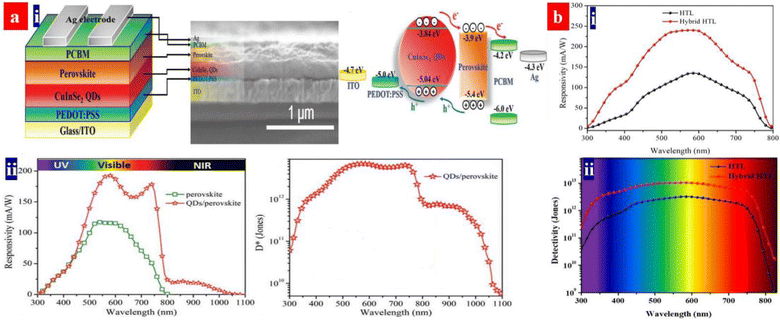 | ||
| Fig. 12 (a) (i) Architecture structure, cross-sectional SEM image and energy band diagram of the PDs. (ii) Responsivity and specific detectivity spectra at 0 V bias voltage. Reproduced with permission.162 Copyright 2020, Wiley-VCH. (b) Responsivity (i) and specific detectivity (ii) of the devices with the hybrid HTL and PEDOT:PSS HTL, respectively, at 0 V bias voltage. Reproduced with permission.163 Copyright 2018, American Chemical Society. | ||
However, optoelectronics with organic functional layers generally suffered from a stability concern. In 2022, Fan et al. proposed a silver bis(trifluoromethanesulfonyl)imide (AgTFSI) treatment that was used to chemically dope the PEDOT:PSS HILs.91 AgTFSI acts as an effective p-dopant for a high charge concentration. It improved the work function and surface potential of the PEDOT:PSS HILs for an interface energy band alignment. The colloidal red QD-LEDs not only yielded a high external quantum efficiency but also exhibited an excellent operation stability in ambient air with a T95 (time for the device brightness to decrease to 95% of its initial brightness) of 4160 hours at an initial brightness of 1000 cd m−2. It is envisioned that similar ionic liquid salt-doping strategies have a great potential to promote the stability of the photodetectors based on the PEDOT:PSS HTLs. In addition, PEDOT:PSS HTLs can be used to fabricate fiber-shaped photodetectors constructed by vertical organic-inorganic heterostructures of zinc oxide/poly(3-hexylthiophene) (P3HT).38 To achieve rapid hole transport, the surface of vertical ZnO/P3HT heterostructure was covered with the thin PEDOT:PSS layer, and the device showed a high responsivity of 156 μA W−1, high specific detectivity of 0.74 × 10⁹ Jones, and a short response/recovery time of <40 ms under zero bias for 365 nm light illumination (32.5 mW cm−2). Other fiber-shaped perovskite PDs can be realized in light of the work based on vertical organic-inorganic heterostructures.38
4.3. Flexible photodetectors with PEDOT:PSS transparent electrodes
ITO films are the most commonly used transparent electrodes for various electronics owning to their high optical transparencies (about 90% transparency in the visible region) and low sheet resistances (10–30 Ω sq−1). However, the ITO transparent electrodes are brittle and expensive, making them unsuitable for flexible electronics. Moreover, the ITO films have a weak transmittance in IR regions,164 which are unsuitable to the PDs with broadband detection as a flexible transparent electrode. In addition, the solution-processed PEDOT:PSS electrodes have the advantages of high optoelectrical characteristics and good flexibility over those of the ITO coated onto thermoplastics substrates.Recently, Gong's group demonstrated a room-temperature solution-processed flexible photodetector with a spectral response from 300 to 2600 nm,165 as shown in Fig. 13. The flexible photodetector possessed a vertical device structure incorporating a perovskite/PbSe QD photoactive layer and a PEDOT:PSS transparent electrode. The PEDOT:PSS electrode was treated by 100 μL of formamidinium iodide (FAI) solutions (dimethylformamide as solvents). After the FAI treatment, the conductivity of the electrode was raised to 1275 S cm−1. By means of a trap-assisted photomultiplication effect, the perovskite/PbSe photoactive layer showed a spectral response to the IR region and an improved photocurrent density in the Vis and IR regions. Under an external bias of −1.0 V, the flexible photodetectors exhibited over 230 mA W−1 responsivity, over 1011 cm Hz1/2 W−1 photodetectivity from 300 to 2600 nm and 70 dB linear dynamic ranges.
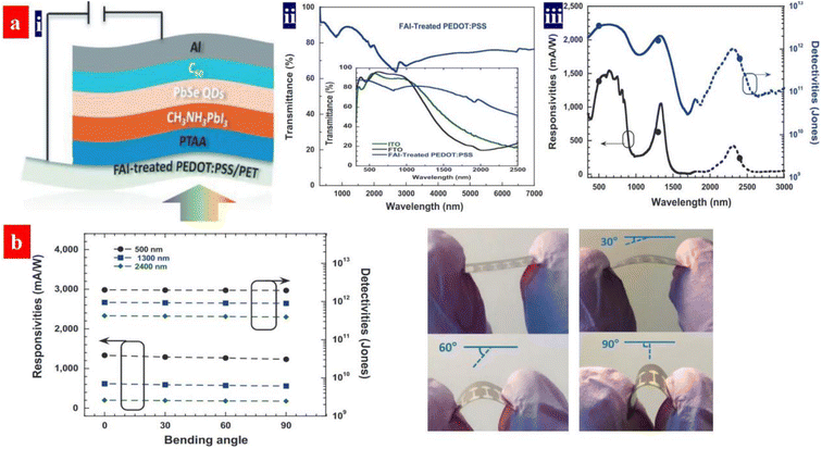 | ||
| Fig. 13 (a) (i) Device architecture, (ii) transmittance spectra of the PEDOT:PPS electrodes, and (iii) responsivities and detectivities of flexible devices versus wavelength. (b) Responsivities and detectivities versus bending degree at a bias of −1 V and the device photographs under a bending angle of 0°, 30°, 60°, and 90°, respectively. Reproduced with permission.165 Copyright 2020, Wiley-VCH. | ||
The electrical conductivity of the FAI-treated PEDOT:PSS transparent electrodes is over 1000 S cm−1.165 However, the electrical conductivity and optical transmittance of the PEDOT:PSS films are not high enough for effective charge collections. We advise that the strong acid-treated PEDOT:PSS electrodes serve as a flexible transparent electrode of the PDs, because of the dramatical raise of the electrical conductivity over 4000 S cm−1 and a large removal of sulfonates for both higher transparency and better stability. Although most of strong acid treatments are certainly detrimental to the underlying thermoplastic substrates and the treatments caused many acid residuals on PEDOT:PSS surfaces, the gentle acid treatments at low temperature developed recently by Fan et al.94,99 have solved the corrosion issues. In the as-proposed gentle treatments, extremely low-concentration (0.1–0.8 M) strong acid/superacid aqueous solutions are used. Especially, the doping temperature is as low as 20–50 °C. In addition, alcohol solvents are employed to soak and more fully wash off the residual acids.
5. Thermoelectric devices based on PEDOT:PSS and its components
The thermoelectric properties of a given material are usually evaluated by the dimensionless figure of merit (ZT), ZT = S2σT/k, where S is the Seebeck coefficient, σ is the conductivity, T is the absolute temperature and k is the thermal conductivity. Sσ2 is defined as the power factor (PF). Because of the high conductivity, the PEDOT:PSS materials can exhibit high thermoelectric properties. In comparison with the conventional thermoelectric materials that are inorganic semimetals or semiconductors, thermoelectric polymers like PEDOT:PSS have the unique merits including low intrinsic thermal conductivity, low cost, no or low toxicity, and high mechanical flexibility.166,167 Both high electrical conductivity and Seebeck coefficient are required for employment in thermoelectric devices.The electrical conductivity of PEDOT:PSS can be greatly enhanced through secondary doping particularly the post acid treatment. Fan et al. carried out the secondary doping of PEDOT:PSS with a DMF solution of an inorganic salt like ZnCl2, CuCl2, InCl3, LiCl, NiCl2 or NaI.168 This can enhance the conductivity from 0.2 to >1400 S cm−1 and the Seebeck coefficient from 14–16 to 26.1 μV K−1. The power factor is thus enhanced to 98.2 μW m−1 K−2. The thermoelectric properties of PEDOT:PSS can be further enhanced when a solution with DMF and thionyl chloride (SOCl2), respectively. For example, Zhang et al. used methylammonium iodide (MAI) solutions in co-solvents of 80 vol% DMF-20 vol% water for the secondary doping of PEDOT:PSS.169 It can enhance the conductivity to 1830 S cm−1 and Seebeck coefficient to 28 μV K−1. The corresponding PF was 144 μW m−1 K−2. In 2021, Fan and co-workers demonstrated a flexible TE based on >99 wt% SOCl2-treated PEDOT:PSS electrodes.96 The simple SOCl2 treatment enabled a homogeneous and smooth PEDOT:PSS film with a conductivity of 2230 S cm−1, a Seebeck coefficient of 22.8 μV K−1, and a high work function of 4.89 eV. The flexible TEs yielded a PF of 115.9 μW m−1 K−2, which was higher than that (91.3–104.0 μW m−1 K−2) of the four kinds of the rigid PEDOT:PSS TEs with acid and NaOH multistep treatments. Although secondary doping can significantly enhance the conductivity, it hardly affects the Seebeck coefficient. For example, although a post treatment with H2SO4 led to a conductivity of higher than 3100 S cm−1, the Seebeck coefficient was only 16.5 μV K−1 and the power factor was 84 μW m−1 K−2.170
Both conductivity and Seebeck coefficient indeed depend on the charge carrier density or doping level of the conducting polymers. Dedoping is feasible way to visibly increase the Seebeck coefficient although the conductivity is decreased.171 PEDOT:PSS can be dedoped with a reducing agent or base. Fan et al. reported the sequential treatments with H2SO4 and NaOH to increase the thermoelectric properties of PEDOT:PSS.170 As shown in Fig. 14, the NaOH treatment partially dedoped the PEDOT:PSS films. Hence, it increases the Seebeck coefficient and lower the electrical conductivity. At the optimal power factor of 334 μW m−1 K−2, the conductivity was 2170 S cm−1, and Seebeck coefficient was 39.2 μV K−1.
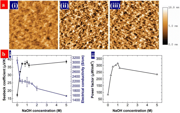 | ||
| Fig. 14 (a) AFM of the films, that are, (i) as-cast, (ii) H2SO4-treated, and (iii) H2SO4 and 0.5 M NaOH-treated PEDOT:PSS films. Scale bar: 2 μm × 2 μm. (b) (i) Seebeck coefficients and conductivities, and (ii) power factors of the PEDOT:PSS films with the NaOH concentration. The PEDOT:PSS films were treated with 1 M H2SO4 for three times and sequentially with NaOH solution. The NaOH concentration at 0 refers to the films without the NaOH treatment. Reproduced with permission.170 Copyright 2017, Wiley-VCH. | ||
Apart from chemical or electrochemical dedoping, dedoping of PEDOT:PSS can occur by light-induced electron transfer between a n-type filler and PEDOT:PSS. Yue et al. found that the exposure of PEDOT:PSS/TiO2 composites to UV light did increase the Seebeck coefficient from 23.5 to 94.3 μV K−1.172 TiO2 can absorb UV light, and the excited electrons can transfer from TiO2 to PEDOT:PSS and thus dedope PEDOT:PSS. This is different from the light effect on the Seebeck coefficient of thermoelectric materials. Light exposure hardly affects the Seebeck coefficient of materials with high thermoelectric properties, while it decreases instead of increasing the Seebeck coefficient of some materials with low thermoelectric properties. They called the light-induced increase in the Seebeck coefficient as photo-enhanced Seebeck effect. This was also observed on the composites of PEDOT:PSS with two-dimensional potassium poly-(heptazine imide) (KPHI).173
Although dedoping can increase the Seebeck efficient, it is at the sacrifice of the conductivity. A remedy to improve the Seebeck coefficient but not remarkably lower the conductivity is energy filtering. Energy filtering has been reported in polymer and inorganic composites.167 Its principle is related to the internal electric field at the interface between the electronic matrix and fillers with different Fermi levels. Because the internal electric field can block the accumulation of charge carriers with low energy at the hot or cold end, it can increase the mean energy (EJ) of the accumulated charge carriers. Thus, the Seebeck coefficient is increased, since it depends to EJ and the Fermi level (EF), S = (EF − EJ)/T.
Energy filtering has been used to improve the thermoelectric properties of PEDOT:PSS. For example, Bi2Te3, which serves as a popular inorganic thermoelectric material, was added into PEDOT:PSS.174 Electron transfer occurs between Bi2Te3 and PEDOT:PSS because of their different Fermi levels. It induces the energy filtering for the charge carriers in PEDOT:PSS and thus increases the Seebeck coefficient. Carbon nanotubes (CNTs) were also studied as the fillers of PEDOT:PSS, and this can induce energy filtering and thus increase the Seebeck coefficient.175–177 Recently, Li et al. reported that ferroelectric BaTiO3 nanoparticles could induce energy filtering and thus increased the Seebeck coefficient of PEDOT:PSS from 23.8 to 40.7 μV K−1.178 The energy filtering is ascribed to the scattering of charge carriers with low energy by the spontaneous electric polarization of BaTiO3 (Fig. 15).
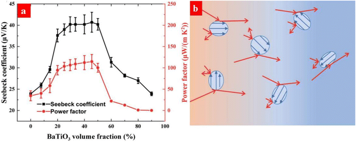 | ||
| Fig. 15 (a) Changes of the Seebeck coefficient and power factor the of PEDOT:PSS/BaTiO3 films. (b) Schematic diagram of energy filtering of PEDOT:PSS by the ferroelectric BaTiO3 nanoparticles (blue dots). The blue and red arrows are for the spontaneous electric polarization in the BaTiO3 nanoparticles and the hole transport, respectively. The charge carriers migrate from the hot end (red regions) to the cold end (blue regions) under a temperature gradient. Reproduced with permission.178 Copyright 2021, Royal Society of Chemistry. | ||
PEDOT:PSS is a p-type thermoelectric polymer. Energy filtering can be induced by forming the composites of PEDOT:PSS and n-type fillers. Guan et al. investigated the thermoelectric properties of PEDOT:PSS and MXene (Ti3C2Tx). The MXene is a n-type 2D material.179 As shown in Fig. 16, the Seebeck coefficient of the PEDOT:PSS/MXene components is greatly enhanced from 23 to 57.3 μV K−1 by the MXene at the loading below 33 wt%. Correspondingly, the power factor is increased from 44.1 to 155 μW m−1 K−2. The high thermoelectric performances are attributed to the energy filtering to the electric field at the interface between MXene to PEDOT:PSS due to the electron transfer. However, the Seebeck coefficient decreases with the increase of the MXene loading when the MXene loading exceeds 33 wt%. It should be mentioned that the MXene, as a n-type TE material, can decrease the Seebeck coefficient.
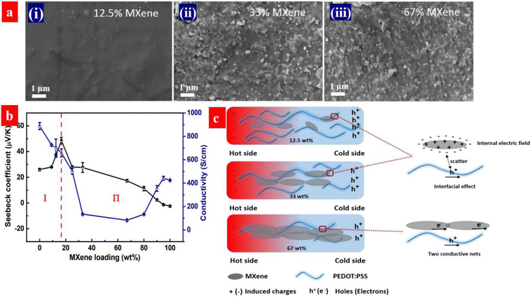 | ||
| Fig. 16 (a) SEM of the MXene/PEDOT:PSS composites with a different MXene loadings: (i) 12.5 wt%, (ii) 33 wt% and (iii) 67 wt%. (b) Seebeck coefficient and electrical conductivity of the composites as a function of the MXene loading. (c) Schematic illustration for the MXene/PEDOT:PSS interface at the different MXene loadings. Reproduced with permission.179 Copyright 2020, American Chemical Society. | ||
Ouyang et al. also observed energy filtering for TE materials coated with a secondary material arising from the scattering of the charge carriers at the surface of the PEDOT:PSS thin films.180 Energy filtering occurs when the secondary layer is an ionic material or a material with a high intrinsic dipole moment. Under temperature gradient, ions can accumulate at the cold end, the so-called Soret effect.181 Fan et al. observed that coating an ionic liquid layer can greatly increase the Seebeck coefficient of PEDOT:PSS to 70 μV K−1 while only slightly lower its conductivity.182 Inspiringly, the highest power factor is 754 μW m−1 K−2 for thermoelectric polymers. The surface energy filtering occurred when the PEDOT:PSS thin film is covered with a layer of quasi-solid ionic liquid gel183 or a layer of polyelectrolyte.184Table 4 summarizes the electrical conductivity, Seebeck coefficient and power factor of the thermoelectric devices based on PEDOT:PSS and its components.
| Material | Method and strategy | σ (S cm−1) | S (μV K−1) | PF (μW m−1 K−2) | Ref. | Year |
|---|---|---|---|---|---|---|
| PEDOT:PSS | 99 wt% SClO2 treatment | 2230 | 22.8 | 115.9 | 96 | 2022 |
| KPHI/PEDOT:PSS | Two-layer structures under light of 420 nm | 1960 | 39.5 | 213 | 173 | 2022 |
| TiO2/PEDOT:PSS | Two-layer structures under light of 365 nm | 1917 | 33.3 | 306 | 172 | 2021 |
| PEDOT:PSS:BaTiO3 | BaTiO3 nanoparticle components | 700 | 40.7 | 117 | 178 | 2021 |
| PEDOT:PSS/PVA/SWCNT | Drop-casting with IL composites | 1800 | 23.7 | 106.1 | 51 | 2021 |
| PEDOT:PSS:Bi2Te3 | Bi2Te3 nanowires composites | 1010 | 47 | 223 | 174 | 2020 |
| PEDOT:PSS/MXene | Energy filtering by an n-type filler | 500 | 57.3 | 155 | 179 | 2020 |
| PEDOT:PSS | PEIE reduces the evaporation of HNO3 | 1580 | 37.5 | 168 | 52 | 2020 |
| PEDOT:PSS/SWCNT | Physical mixing and DMSO/NaOH treatments | 1700 | 55.6 | 526 | 177 | 2019 |
| PSSH/PEDOT:PSS | Two-layer structures with acid and base treatments | 2120 | 43.5 | 401 | 184 | 2018 |
| PSSNa/PEDOT:PSS | Two-layer structures with acid and base treatments | 1732 | 48.1 | 401 | 184 | 2018 |
| PEDOT:PSS/IL | Acid treatment and energy filtering by IL layer fillers | 1580 | 69 | 754 | 182 | 2018 |
| PEDOT:PSS | MAI solutions in co-solvent of 80 vol% DMF-20 vol% water | 1830 | 28 | 144 | 169 | 2018 |
| PEDOT:PSS | H2SO4 and NaOH treatments | 2170 | 39.2 | 334 | 170 | 2017 |
| PEDOT:PSS/Te/SWCNT | Energy filtering by telluride nanorod and SWNT components | 139 | 118 | 206 | 50 | 2017 |
| PEDOT:PSS:SWCNT | SWCNT components | 1350 | 59 | 464 | 176 | 2017 |
| PEDOT:PSS | Addition of DMSO and PEO | 1061 | 38.4 | 157.4 | 47 | 2015 |
| PEDOT:PSS | TSA and hydrazine/DMSO treatments | 1647 | 49.3 | 318.4 | 48 | 2014 |
6. Stretchable PEDOT:PSS conductors
Stretchable electronics, such as strain sensors, stretchable OSCs/PSCs, organic LEDs/quantum dot LEDs and TEs, are regarded as among the next-generation ubiquitous electronics. Such stretchable devices typically rely on the most commonly used stretchable conductors, namely PEDOT:PSS.185–187 Except a good stretchability required by strain sensors, the stretchable conductors should be of high sensitivity to each mechanical deformation, e.g., bending, twisting, and tensile strains; while for a optoelectronic device such as photovoltaic cells and LEDs, the stretchable conductors serve as a stretchable transparent electrode that should have high optoelectrical properties and good durability against cyclic stretching-relaxing and long-term loading. Recently, novel methodologies have been proposed to realize the high-performance stretchable devices based on the PEDOT:PSS.6.1. Strain sensors
Strain sensors require a key stretchable conductor that affords mechanical deformations for at least 104 cycles while still maintaining an initial conductivity in a relaxing status and show a high sensitivity. The sensitivity is known as gauge factor (GF). GF = (ΔR/Ro)/ε, where ΔR/Ro is the normalized change in electrical resistance, and ε is the tensile strain of strain sensors. PEDOT:PSS is regarded as the most promising stretchable polymer conductor in epidermal- and implantable sensors, and the PEDOT:PSS-based strain sensors had been widely employed as electronic skins, health monitors, artificial intelligence, food fermentation monitors, etc.188–192Fan et al. introduced a highly conductive, stretchable and large-size (4.7 cm × 4.7 cm) PEDOT:PSS film.105 The film was embedded into PDMS elastomers. The strain sensors showed a high sensitivity of 22 at 20% strain. In 2018, Fan et al. also demonstrated a strain sensor with a sandwich structure of poly(vinyl) alcohol (PVA)–PEDOT:PSS blends/conductive PEDOT:PSS/PDMS.103 The devices exhibited a high sensitivity of 110 at 30% strain and stable responses in both stretching–relaxing and long-term loading tests. However, the sensing strains (≤30%) were not high enough for strain sensors. In 2020, He's group made a breakthrough in sensing range and reliability of the strain sensors (Fig. 17).193 They reported a stretchable strain sensor consisting of Ag nanowires (NWs) and PEDOT:PSS patterned micro-structures. Owing to the micro-structure design of PEDOT:PSS, strong adhesion between PEDOT:PSS and its underlying layers and superior conductivity of Ag NWs, the devices showed a sensitivity of 10.2, a wide sensing range (0–100%), a high reliability for >2000 cycles, and distinct temperature response (31–35 °C). Recently, Xu et al. reported free-standing self-powered temperature-strain dual sensors based on PEDOT:PSS/carbon nanocoils (CNCs)–PVA composite films via a simple drop casting.194 The Seebeck coefficient of the PEDOT:PSS/CNC films was 19 μV K−1. This PEDOT:PSS material supplied the thermoelectric powers to detect the temperatures and strains. Under a constant temperature gradient of 30 K, strains from 1% to 10% were detected without any external power supply. The composite films with an array have detected effectively the temperatures of the human's fingers and the motions of the wrist.
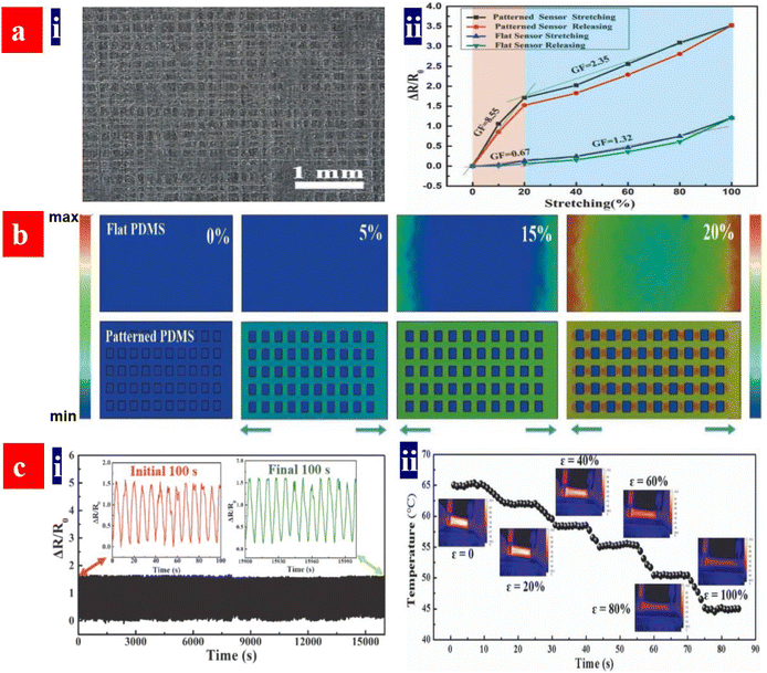 | ||
| Fig. 17 (a) (i) Optical micrograph of the polyacrylonitrile grids fabricated by near-field electrospinning with a spacing distance (d) of 150 μm, and (ii) relative resistance changes versus tensile strains of the strain sensors based on the flat and patterned electrodes. (b) Stress distributions of both flat- and patterned PDMS substrates with d = 150 μm during the first straining process. (c) (i) Relative resistance changes versus times (1–16000 s) of the sensors under ε = 20%, and (ii) temperature changes versus strains for the strain sensors. Reproduced with permission.193 Copyright 2020, Wiley-VCH. | ||
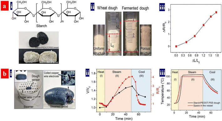
Monitoring food processing helps to achieve high quality and high productivity of the food products. In 2021, Ouyang et al. demonstrated a strain sensor with biocompatible blends of an intrinsically conducting polymer for real-time monitoring of starch-based food processing (Fig. 18).86 It monitored the fermentation, steaming, storage and refreshing processed of the food preparation in real time. During fermentation, the volume expansion of the dough with PEDOT:PSS and starches led to an increased resistance; and then the dough volume expanded to the maximum volume that corresponded to the largest resistance. When the resistance becomes stable, the fermentation was finished. The breads with starches and PEDOT:PSS monitored the storage, because volume variation and crevice generation during storage induced a change of the resistances. In the future, it will be revolutionary to invent the multifunctional strain sensors because of the broad applications in human/machine interaction, electronic skins, food production and safety, and wearable sensing electronics.
 | ||
| Fig. 18 (a) (i) Molecular structure of starch and photographs of a starch bread involving PEDOT:PSS and as-cast starch breads. (ii) A starch/PEDOT:PSS dough showing a volume expansion in the fermentation. (iii) Resistance variation versus length variation of the dough. Rinitial = 78 kΩ, Linitial = 1.5 cm. (b) (i) Photographs of the setup and a starch/PEDOT bread. (ii) Resistance (R/Rinitial) and volume (V/Vinitial) changes of the dough in the steaming process. Rinitial = 75 kΩ, Vinitial = 1.5 cm3. (iii) Real-time temperatures of the dough during steaming. Reproduced with permission.86 Copyright 2021, Wiley-VCH. | ||
6.2. Stretchable photovoltaic cells
ITO is an undesirable electrode material in stretchable solar cells owing to its brittleness and low conductivity in a flexing test. Wrinkled and stretchable solar cells were previously realized through spin-coating a PEDOT:PSS transparent electrode on pre-strained PDMS elastomeric substrates195 or transferring a solar cell foil on pre-strained elastomeric substrates.196,197 PDMS is one of the most commonly used elastomer substrates in stretchable electronics. However, the PDMS stamps become mechanically robust and tough when stored long-term in ambient air, besides, plenty of large wrinkles and cracks appeared in cyclic stretching-relaxing tests. Therefore, the usage of a soft and durable elastomer as PDMS alternatives is critical for the PEDOT:PSS electrodes and the integrated stretchable devices.Chen et al. demonstrated a stretchable OSC based on PEDOT:PSS transparent electrodes.198 The PEDOT:PSS aqueous solutions, which contained 5 vol% DMSO and 10 vol% of Zonyl fluorosurfactant, were stirred overnight prior to use. Then, the PEDOT:PSS electrodes were coated on elastomeric substrates of PDMS and 3M VHB 4905 tape (3M tape), respectively. This 3M tape involving modified acrylic molecules did have a high elasticity and viscoelasticity with a large impact force absorption, and the tape provided a weather resistance. On the basis of the structure of 3M tapes/PEDOT:PSS electrodes/PTB7:PC71BM/eutecticgallium–indium (EGaIn), the stretchable OSCs showed a PCE of 5.2% under illumination of AM1.5 solar simulator (Fig. 19). This PCE is 30% higher than that of the stretchable devices fabricated onto pre-strained PDMS substrates. The raised PCE is due to the favorable surface status of the PEDOT:PSS/3M tapes with small and dense wrinkles that can provide a better interface for the deposition of active layers. Besides, the OSCs had an excellent mechanical stability, maintaining 80% of its original PCE at 20% strain for 50 cycles. Despite the moderate PCE (5.2%) of the stretchable devices, the PCE will be improved further via increasing the electrode conductivity, inserting a buffer layer, and using more efficient ternary active layers.
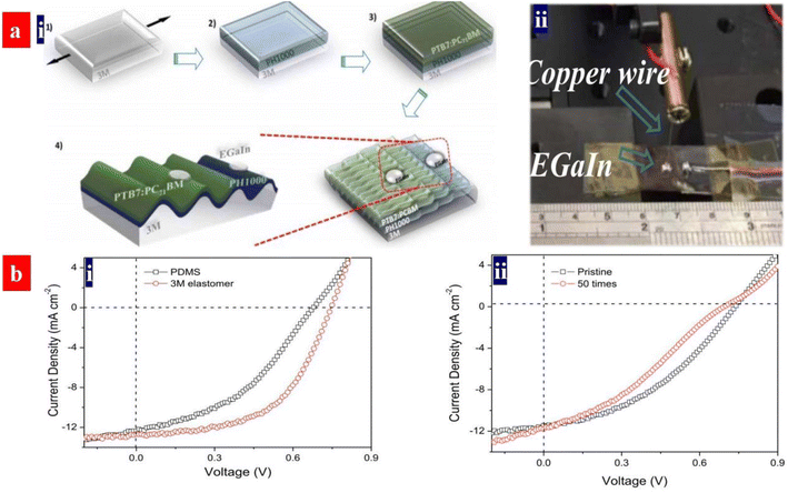 | ||
| Fig. 19 (a) (i) Illustration of the fabrication process of stretchable OSCs ((1) pre-strain and attachment to glass substrates, (2) spin-coating of PEDOT:PSS, (3) spin-coating of active layers, and (4) removal of the glass and relaxation of the pre-strain), and (ii) images of the solar cell and characterization system. (b) (i) J–V curves of the stretchable OSCs fabricated on PDMS and 3M tapes, and (ii) J–V curves of the stretchable OSCs before and after stretching at 20% strain for 50 cycles. Reproduced with permission.198 Copyright 2017, Elsevier. | ||
Organic solar cells (OSCs) can be made as an intrinsically stretchable power source via PEDOT:PSS electrode and HTL modifications and a blending strategy of active layers. In 2022, Lee et al. demonstrated an intrinsically stretchable OSC that exhibited a high PCE and excellent stretchability (Fig. 20).199 The device configuration is illustrated as follows: thermoplastic polyurethane (PU) substrates/modified PEDOT:PSS (PH1000) electrodes/modified PEDOT:PSS (P VP AI 4083) HTLs/active layers/PNDIT-F3N-Br/EGaIn. 5 vol% dimethyl sulfoxide (DMSO) was used to increase the electrical conductivity of the PH1000 electrodes; 2 vol% polyethylene glycol (PEG) was employed to prolong the elongation of the PH1000 electrodes; and 0.5 vol% Zonyl fluorosurfactant FS-300 was blended to improve the surface wettability of the P VP AI 4083 HTLs. The mechanically robust active layers were constructed via the addition of a high-molecular weight (MW: 408 kg mol−1) polymer acceptor (PA) to PM6:Y7 active layers. Because the long PA chains served as molecular bridges between different domains and dissipated mechanical stresses for charge transport, high-MW PA addition could boost the stretchability and PCE of the photovoltaic cells with 20 wt% PA. The stretchable solar cells yielded a high PCE of 11.7% and the devices retained 84% of the initial PCE in a cyclic stretching-releasing test for 100 cycles at 15% strain.
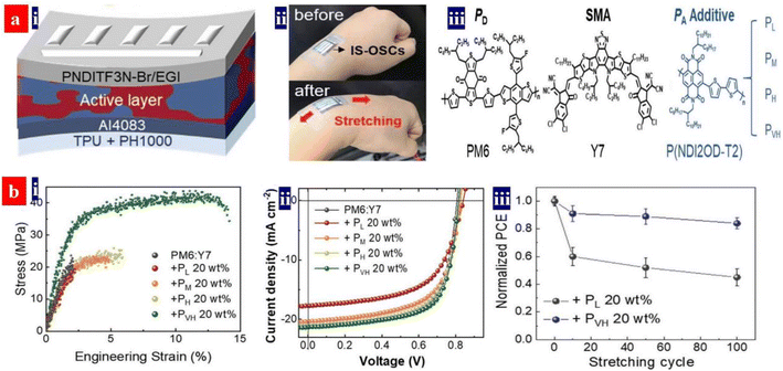 | ||
| Fig. 20 (a) (i) Stretchable OSC structure, (ii) photographs, and (iii) molecular structures of the PA additives. (b) (i) Stress–strain curves of PM6:Y7 with 20 wt% of PAs of different MWs, (ii) J–V curves of the stretchable OSCs as functions of PAs with different MW, and (iii) normalized PCE curves of the stretchable devices in the flexing tests. Reproduced with permission.199 Copyright 2022, Wiley-VCH. | ||
A stretchable active layer of OSCs was also obtained recently via usage of a polymer donor (PBB1-Cl) as the third component.200 It regulated the morphology and molecular accumulation of PM6:Y6-Bo-4Cl active layers. After the addition of 20% PBB1-Cl, the tensile strength and elongation at the break of the ternary blend layers increased from 2.00 to 9.12 N and from 5.83% to 26.86%, respectively. The long elongation is attributed to a formation of a better intertwined and ordered intermolecular stacking in the ternary blends. Li's group compared the mechanical properties of several representative active layers of organic solar cells.201,202 Among the active layers, the PM6:PC60BM films had the maximum crack-onset strain of 4.58% and the highest toughness of 169.47 J cm−3.201 We envision that the PM6:PC60BM active layers which were blended with a third component are suitable to fabricate more efficient and mechanically robust OSCs based on stretchable PEDOT:PSS electrodes. There is a high probability that this ternary active layer blend will allow for the creation of stretchable photovoltaic cells that can show a high PCE of over 15% along with a large tensile strain over 25%.
6.3. Intrinsically stretchable PLEDs
A wrinkled configuration of optoelectronics is not considered to be intrinsically stretchable. Intrinsically stretchable optoelectronics require that all of the components (underlying substrates, photoactive layers, both electrodes sandwiched the active layers, and buffer layers) are intrinsically stretchable. Such unprecedented devices on skin-like underlying substrates should be highly soft, intrinsically stretchable and highly efficient.203–207 Intrinsically stretchable polymer materials have the promise of good strain tolerance.208,209 However, it has been very challenging to invent these kinds of intrinsically stretchable solar cells and LEDs with considerably high efficiency.Inspiringly, Bao's group recently demonstrated a stretchable all-polymer LED that comprised a stretchable anode of PEDOT:PSS blended with polyrotaxane (PR) and a hole injection layer of PEDOT:PSS/Triton X (8 nm).210 This PR is a cross-linking agent and it forms from PEG and α-cyclodextrin (α-CD), exhibiting free movement of the cyclic α-CD along the linear PEG.211,212 A resultant three-dimensional (3D) network was prepared with the PR agents.213 Here, the anode (150 nm) was spin-coated on a soft substrate of PVDF-HFP (100 μm), and a stretchable light-emitting layer of Super Yellow (SY) with polyurethane was innovatively employed. The resultant all-polymer-based LED yielded a high brightness of 7450 cd m−2, current efficiency of 5.3 cd A−1, and stretchability of up to 100% strain. The work showed an advancement towards high-performance intrinsically stretchable LEDs, and it improved visual human–electronic interfaces for stretchable displays.
However, doping treatments and engineering strategies to making elastic and durable transparent electrodes are emergent and significant for the development of the intrinsically stretchable optoelectronics. Brightness, current efficiency, tensile strains, durability and operation lifetimes should be raised further in the next-generation LEDs. Besides, the device durability should be investigated in at least 104 stretching-relaxing tests at a strain no lower than 30% and long-time (e.g., 5 min) loading tests for a true adaptation of the lighting and display products.
6.4. Stretchable thermoelectrics
The development of stretchable and power-supply systems has the advantages of lightweight, wearability, self-sustaining and high compatibility with human skins.5,97,214–218 However, the usage of as-cast PEDOT:PSS films is currently constrained by their intrinsic small elongation of <2.0%. An elastomer blending strategy was commonly used to raise the mechanical property, while DMSO and ionic liquids were generally employed to raise the electrical conductivity of the PEDOT:PSS materials.In 2018, Taroni et al. showed a tough and processable self-standing film based on PEDOT:PSS and commercial elastomeric polyurethane (Lycra) blends.219 The PEDOT:PSS (Clevios PH1000) was freeze dried, and then dispersed into DMSO followed by a probing sonication. An unprecedented strain at break of 700 ± 150% was reached for the TEs with a blend containing 90 wt% Lycra. After EG bath, the thermoelectric films showed an electrical conductivity of 79 S cm−1 and a Seebeck coefficient of 16 μV K−1. Subsequently, in 2020, Ouyang et al.84 prepared a stretchable and transparent ionogel with high thermoelectric properties via a drop-casting method (Fig. 21). The ionogels made of waterborne polyurethane (WPU) and 1-ethyl-3-methylimidazolium dicyanamide (EMIM:DCA). The ionogels with 40 wt% EMIM:DCA possessed a superior stretchability of up to 156%, a low tensile strength of 0.6 MPa, and a low Young's modulus of 0.6 MPa. The stretchable ionogels exhibited a high ionic thermovoltage of 34.5 mV K−1 along with a high ionic conductivity of 8.4 mS cm−1.
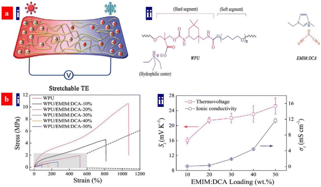 | ||
| Fig. 21 (a) Schematic diagram of device operation, and chemical structures of WPU and EMIM:DCA. (b) (i) Stress–strain characteristics of the WPU film and WPU/EMIM:DCA ionogels; and (ii) profiles of thermovoltage and ionic conductivity of WPU/EMIM:DCA ionogels with various EMIM:DCA loading. Reproduced with permission.84 Copyright 2020, Wiley-VCH. | ||
In 2021, Wen et al. realized a stretchable TE fiber that consisted of PEDOT:PSS and WPU and ionic liquids of 1-ethyl-3-methylimidazolium tricyanomethanide (EMIM TCM) via using one-step wet-spinning approach (Fig. 22).220 In the PEDOT:PSS/WPU composite fibers, WPU not only acts as an elastomeric matrix, but also it has a template effect on (i) improving the packing order and (ii) increasing the linearity of the PEDOT chains during wet-spinning. 10 wt% EMIM TCM composites were added to the PEDOT:PSS aqueous solution to raise the electrical conductivity. The composite fibers showed a desirable wearable merit and a power factor of 26.1 μW m K−2. The resultant PEDOT:PSS/WPU composite fibers not only possessed a good intrinsic stretchability with an elongation-at-break of >30%, but they also exhibited an excellent performance stability and self-recoverability in cyclic stretching tests.
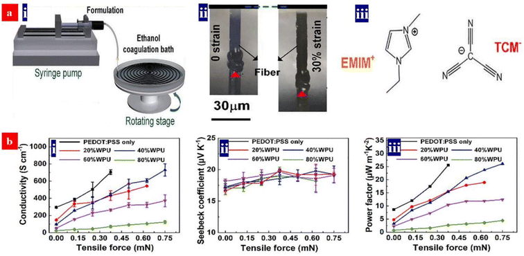 | ||
| Fig. 22 (a) (i) Schematic diagram of the wet-spinning fabrication of PEDOT:PSS/WPU composite fibers; (ii) photographs of the composite fibers blended with EMIM:TCM at relaxing and stretching states; and (iii) molecular structure of EMIM:TCM. (b) Dependences of electrical conductivity (i) Seebeck coefficient (ii) and PF (iii) of the PEDOT:PSS fiber and the composite fibers under different tensile loading with the tensile forces of 0, 0.125, 0.25, 0.375, 0.5, 0.625 and 0.75 mN, respectively. Reproduced with permission.220 Copyright 2021, Elsevier. | ||
In the future, we suggest that metal ionic liquids (MIL) with TFSI− groups, strong acids, and bases are used to balance the electrical conductivity, Seebeck coefficient and operation stability of the TE fibers. The reasons are obvious, such as the superior conductivity of the strong acid-treated PEDOT:PSS films,94,99 a potentially high stability of the devices based on the MIL-treated PEDOT:PSS films,91 and the dedoping effect induced by the bases (e.g., NaOH170). Notably, the strong acid doping should be suitable to the composite fibers through substantially reducing the doping temperatures and dopant concentrations. This gentle acid approach can avoid a chemical corrosion of strong acids to most of underlying plastic substrates and the elastomers involving WPU. Therefore, a highly thermoelectric, stable and stretchable TE based on PEDOT:PSS can be realized and it's promising for wearable and portable energy supply.
7. Conclusion and outlook
State-of-the-art approaches and methodologies were reviewed and proposed to raise the optoelectrical properties, work function, thermoelectric properties, stretchability, wettability and stability of the PEDOT:PSS films and stretchable conductors. As displayed in Fig. 23, the latest innovative methods include: (i) CF3SO3H doping, HClO4 doping, solution shearing, solvent shearing, and layer-by-layer treatments for the electrode preparations; (ii) sulfonate, sodium salt, cesium salt, F4-TCNQ, DMF, ionic liquids and urea treatments and component strategies using NPB, PTAA, PANI-phenoxazine and MoO3 for the HTL preparations; (iii) secondary solvent treatments, strong acid doping, SClO2 doping, energy-filtering methodologies, n-type TE composites and dedoping for the TE layer realizations; (iv) soft material blending, underlying substrate selection methodologies, and ionogel formulation for the stretchable conductor realizations; and (v) elastomeric blends and freeze drying for the stretchable TE fabrications. There has been much intensive research and significant progress on optoelectronics and thermoelectrics with the multifunctional PEDOT:PSS materials. Nevertheless, there are still major challenges and shortcomings to overcome that have negative impact on the development of related devices fabricated from PEDOT:PSS-based materials. Many insightful suggestions for success towards such necessary achievements are provided below.First, these modification treatments and film-deposition-processing approaches not only raise the electrical conductivity, work function, stretchability, and wettability of the resultant PEDOT:PSS films, but perovskite layers fabricated on top of these films are also induced into the formation of large grain sizes, less defects, and overall higher crystallinity. It is advised that both modification treatments and processing approaches for PEDOT:PSS films should be organically combined, meaning that both modification methods and processing approaches should be universal and suitable to various kinds of devices towards higher performance. Additionally, a combined treatment has a higher probability of further promoting charge transfer into PEDOT:PSS matrices while synergistically improving film properties. Thus, it is believed that such will pave an avenue to enhance the performances and prolong the operational lifetimes of corresponding solar cells, LEDs, PPDs, TEs, strain sensors, and flexible and stretchable electronics.
Then, there are several concerns that should be openly considered with regards to electrode fabrication and implementation. (i) There is currently no route to obtain PEDOT:PSS electrodes with a high enough conductivity comparable to those of commercial ITO electrodes or Ag nanowire electrodes. It has been found that a better morphology with refined PEDOT-rich nanoparticles and nanofibrils can largely improve the electrical conductivity.94 Thus, new methods to improve film morphology as well crystallinity should be continuously pursued. (ii) There are few studies that formulate links between PEDOT:PSS film overall stability and related device performance. Overall PEDOT:PSS stability includes electrical, electrochemical, work function, structural, and morphological stability against ambient air, UV light, and relatively high temperatures. Although PEDOT:PSS can exhibit a raised stability and a good conductivity, they aren't optimal for high-performance electronic devices. In order to make stabilized PEDOT:PSS films; PEDOT crystallinity, electronic structure, PEDOT/PSS ratio, molecular interactions, surface hydrophobicity, and interfacial adhesion should be considered together and optimized concurrently. (iii) Micro-patterned PEDOT:PSS films (or PEDOT:PSS pixels) are desirable for broad applications in solar cells, high-resolution micro-displays, touch sensors, and flexible and stretchable electronics. Advanced photolithography and plasma-etching techniques will be required for future realization of micro-patterned films and high-resolution PEDOT:PSS pixels.
Next, sulfonate groups, dopant molecules, and metal ion dopants can potentially migrate towards, diffuse into, and potentially poison other active components of PSC devices, leading to detrimental reactions and poor photovoltaic performance. Indeed, the underlying mechanisms of device-performance degradation and failure modes are somewhat ambiguous. In order to improve the photovoltaic performance, one method is to use unique dopants involving fluorochlorine polar molecular bonds and hydrophilic groups. The use of these dopants has the advantages of improving the work function of the PEDOT:PSS thin films, inducing more seamless contact at interfaces, reducing the sulfonate levels in matrices, and inducing higher crystallinity of subsequent perovskite layers. It will also induce shorter charge transport times and higher charge carrier lifetimes for these PSCs. Another method is to employ an interfacial shield with a chemically stable metal oxide layer (e.g., MoO3, NiOx, or Al2O3). Such shielding treatments using inert metal oxides is also favorable for improving charge-carrier transport and hole extraction.
Finally, an improved encapsulation is critical to promote the stability of these optoelectronic devices. The PEDOT:PSS material is intrinsically sensitive to moisture and oxygen, which can degrade its optoelectrical properties over time. It is challenging to fully avoid the permeation of water and oxygen from ambient air into devices. Researchers explored different strategies to improve the stability of the optoelectronic devices via using self-encapsulating nucleation layers221 and plasma-enhanced molecular layer deposition,222 to ensure long-term functionality and reliability of these devices. Besides, two-dimensional materials such as graphene and Ti3C2 (MXene) can restrain the penetration of water and oxygen into devices. Thus, a blend of standard packaging materials with such two-dimensional materials has a high probability of improving device stability. Another possibility is to employ an encapsulation film, e.g., an organic film sandwiched with a stable metal oxide film (SiNx, SiO2, SiO1−xNx, Al2O3, or ZrO2), which is one of the best options for device packaging. These metal oxide films are usually prepared through using low-temperature plasma enhanced chemical vapor deposition or atomic layer deposition. Notably, for curved devices, an inorganic-organic-inorganic (IOI) encapsulation film with a total of 8 to 10 μm thickness is suggested; whereas, for flexible and stretchable devices, an IOI encapsulation layer with a total of 1 to 2 μm thickness is advised for employment. Indeed, these packaging materials and encapsulation technologies are critical for an adaptation of curved, flexible, and stretchable optoelectronics and thermoelectrics. It is hoped that by means of the aforementioned methods, scientists and engineers can collaborate together for a brighter future of these OSCs, PSCs, LEDs, PPDs, TEs, touch sensors, and flexible and stretchable devices based on PEDOT:PSS materials.
Conflicts of interest
There are no conflicts to declare.Acknowledgements
We are grateful for financial support from the Ningbo Natural Science Foundation (2021J195), and Zhejiang Provincial Natural Science Foundation of China under Grant no. LGG22F040003.Notes and references
- C. Z. Liao, C. H. Mak, M. Zhang, H. L. W. Chan and F. Yan, Adv. Mater., 2015, 27, 676 CrossRef CAS PubMed.
- H. Huang, Y. Zhao, T. Cong, C. Li, N. Wen, X. Zuo, Y. Guo, H. Zhang, Z. Fan and L. Pan, Adv. Funct. Mater., 2022, 32, 2110777 CrossRef CAS.
- B. J. Worfolk, S. C. Andrews, S. Park, J. Reinspach, N. Liu, M. F. Toney, S. C. B. Mannsfeld and Z. N. Bao, Proc. Natl. Acad. Sci. USA, 2015, 112, 14138 CrossRef CAS PubMed.
- Y. Qi, M. Almtiri, H. Giri, S. Jha, G. Ma, A.-K. Shaik, Q. Zhang, N. Pradhan, X. Gu, N.-I. Hammer, D. Patton, C. Scott and Q. Dai, Adv. Energy Mater., 2022, 12, 2202713 CrossRef CAS.
- M. Abarkan, A. Pirog, D. Mafilaza, G. Pathak, G. N'Kaoua, E. Puginier, R. O'Connor, M. Raoux, M. J. Donahue, S. Renaud and J. Lang, Adv. Sci., 2022, 9, 2105211 CrossRef CAS.
- S. Gong and W. L. Cheng, Adv. Electron. Mater., 2017, 3, 1600314 CrossRef.
- J. Lu, W. Feng, G. Mei, J. Sun, C. Yan, D. Zhang, K. Lin, D. Wu, K. Wang and Z. Wei, Adv. Sci., 2020, 7, 2000689 CrossRef CAS.
- Y. Wang, C. X. Zhu, R. Pfattner, H. P. Yan, L. H. Jin, S. C. Chen, F. Molina-Lopez, F. Lissel, J. Liu, N. I. Rabiah, Z. Chen, J. W. Chung, C. Linder, M. F. Toney, B. Murmann and Z. N. Bao, Sci. Adv., 2017, 3, e1602076 CrossRef PubMed.
- X. T. Hu, X. C. Meng, L. Zhang, Y. Y. Zhang, Z. R. Cai, Z. Q. Huang, M. Su, Y. Wang, M. Z. Li, F. Y. Li, X. Yao, F. Y. Wang, W. Ma, Y. W. Chen and Y. L. Song, Joule, 2019, 3, 2205–2218 CrossRef CAS.
- Y. Cui, F. Zhang, G. Chen, L. Yao, N. Zhang, Z. Liu, Q. Li, F. Zhang, Z. Cui, K. Zhang, P. Li, Y. Cheng, S. Zhang and X. Chen, Adv. Mater., 2021, 33, 2100221 CrossRef CAS PubMed.
- D. H. Kim, J. H. Ahn, W. Mook Choi, H. S. Kim, T. H. Kim, J. Song, Y. Y. Huang, Z. Liu, C. Lu and J. A. Rogers, Science, 2008, 320, 507 CrossRef CAS PubMed.
- D. J. Lipomi, M. Vosgueritchian, B. C. Tee, S. L. Hellstrom, J. A. Lee, C. H. Fox and Z. Bao, Nat. Nanotechnol., 2011, 6, 788 CrossRef CAS.
- M. L. Hammock, A. Chortos, B. C.-K. Tee, J. B.-H. Tok and Z. Bao, Adv. Mater., 2013, 25, 5997 CrossRef CAS PubMed.
- T. Someya, Z. Bao and G. G. Malliaras, Nature, 2016, 540, 379 CrossRef CAS PubMed.
- D. Son, J. Lee, S. Qiao, R. Ghaffari, J. Kim, J. E. Lee, C. Song, S. J. Kim, D. J. Lee, S. W. Jun, S. Yang, M. Park, J. Shin, K. Do, M. Lee, K. Kang, C. S. Hwang, N. Lu, T. Hyeon and D.-H. Kim, Nat. Nanotechnol., 2014, 9, 397 CrossRef CAS PubMed.
- D. H. Kim and Y. Lee, Nat. Nanotechnol., 2015, 10, 570 CrossRef CAS.
- I. R. Minev, P. Musienko, A. Hirsch, Q. Barraud, N. Wenger, E. M. Moraud, J. Gandar, M. Capogrosso, T. Milekovic, L. Asboth, R. F. Torres, N. Vachicouras, Q. Liu, N. Pavlova, S. Duis, A. Larmagnac, J. Voeroes, S. Micera, Z. Suo, G. Courtine and S. P. Lacour, Science, 2015, 347, 159 CrossRef CAS PubMed.
- Y. B. Cheng, A. Pascoe, F. Huang and Y. Peng, Nature, 2016, 539, 488 CrossRef CAS.
- G. Zeng, W. Chen, X. Chen, Y. Hu, Y. Chen, B. Zhang, H. Chen, W. Sun, Y. Shen, Y. Li, F. Yan and Y. Li, J. Am. Chem. Soc., 2022, 144, 8658–8668 CrossRef CAS PubMed.
- D. J. Lipomi and Z. Bao, MRS Bull., 2017, 42, 93 CrossRef.
- J. R. Tumbleston, B. A. Collins, L. Yang, A. C. Stuart, E. Gann, W. Ma, W. You and H. Ade, Nat. Photonics, 2014, 8, 385 CrossRef CAS.
- H. Kang, S. Jung, S. Jeong, G. Kim and K. Lee, Nat. Commun., 2015, 6, 6503 CrossRef CAS.
- J. Tong, S. Xiong, Y. Zhou, L. Mao, X. Min, Z. Li, F. Jiang, W. Meng, F. Qin, T. Liu, R. Ge, C. Fuentes-Hernandez, B. Kippelen and Y. Zhou, Mater. Horiz., 2016, 3, 452 RSC.
- S. I. Na, S. S. Kim, J. Jo and D. Y. Kim, Adv. Mater., 2008, 20, 4061 CrossRef CAS.
- T. Liu, L. Sun, X. Dong, Y. Jiang, W. Wang, C. Xie, W. Zeng, Y. Liu, F. Qin, L. Hu and Y. Zhou, Adv. Funct. Mater., 2021, 31, 2107250 CrossRef CAS.
- T. Y. Qu, L. J. Zuo, J. D. Chen, X. L. Shi, T. Zhang, L. Li, K. C. Shen, H. Ren, S. Wang, F. M. Xie, Y. Q. Li, A. K. Y. Jen and J. X. Tang, Adv. Opt. Mater., 2020, 8, 2000669 CrossRef CAS.
- D. Koo, S. Jung, J. Seo, G. Jeong, Y. Choi, J. Lee, S. M. Lee, Y. Cho, M. Jeong, J. Lee, J. Oh, C. Yang and H. Park, Joule, 2020, 4, 1021 CrossRef CAS.
- X. Zheng, L. Zuo, F. Zhao, Y. Li, T. Chen, S. Shan, K. Yan, Y. Pan, B. Xu, C.-Z. Li, M. Shi, J. Hou and H. Chen, Adv. Mater., 2022, 34, 2200044 CrossRef CAS PubMed.
- W. S. Yang, J. H. Noh, N. J. Jeon, Y. C. Kim, S. Ryu, J. Seo and S. I. Seok, Science, 2015, 348, 1234 CrossRef CAS PubMed.
- G. Yang, C. Chen, F. Yao, Z. L. Chen, Q. Zhang, X. L. Zheng, J. J. Ma, H. W. Lei, P. L. Qin, L. B. Xiong, W. J. Ke, G. Li, Y. F. Yan and G. J. Fang, Adv. Mater., 2018, 30, 1706023 CrossRef.
- D. Yang, R. Yang, J. Zhang, Z. Yang, S. Liu and C. Li, Energy Environ. Sci., 2015, 8, 3208 RSC.
- H. Yu, Y. Xie, J. Zhang, J. Duan, X. Chen, Y. Liang, K. Wang and L. Xu, Adv. Sci., 2021, 8, 2004510 CrossRef CAS PubMed.
- Z. Wang, L. Zeng, C. Zhang, Y. Lu, S. Qiu, C. Wang, C. Liu, L. Pan, S. Wu, J. Hu, G. Liang, P. Fan, H.-J. Egelhaaf, C. J. Brabec, F. Guo and Y. Mai, Adv. Funct. Mater., 2020, 30, 2001240 CrossRef CAS.
- P. Lin, W. Zhang, L. Tian, L. Jia, F. Wen, G. Duan, X. Zhou, S. Zhou, F. Zhang, Y. Jiang, T. Chen, F. Liu, S. Yang and Y. Huang, ACS Appl. Energy Mater., 2021, 4, 4408–4415 CrossRef CAS.
- C. K. Liu, H. L. Loi, J. Cao, G. Tang, F. Liu, Q. Huang, X. Liang and F. Yan, Small Struct., 2021, 2, 2000084 CrossRef CAS.
- C. Xie, C.-K. Liu, H.-L. Loi and F. Yan, Adv. Funct. Mater., 2020, 30, 1903907 CrossRef CAS.
- J.-Y. Lin, F.-C. Hsu, C.-Y. Chang and Y.-F. Chen, J. Mater. Chem. C, 2021, 9, 5190–5197 RSC.
- X. Du, W. Tian, J. Pan, B. Hui, J. Sun, K. Zhang and Y. Xia, Nano Energy, 2022, 92, 106694 CrossRef CAS.
- F. P. G. de Arquer, A. Armin, P. Meredith and E. H. Sargent, Nat. Rev. Mater., 2017, 2, 16100 CrossRef.
- L. Dou, Y. M. Yang, J. You, Z. Hong, W.-H. Chang, G. Li and Y. Yang, Nat. Commun., 2014, 5, 5404 CrossRef CAS PubMed.
- Q. J. Sun, Y. A. Wang, L. S. Li, D. Wang, T. Zhu, J. Xu, C. H. Yang and Y. F. Li, Nat. Photonics, 2007, 1, 717 CrossRef CAS.
- K. Goushi, K. Yoshida, K. Sato and C. Adachi, Nat. Photonics, 2012, 6, 253 CrossRef CAS.
- X. L. Dai, Z. X. Zhang, Y. Z. Jin, Y. Niu, H. J. Cao, X. Y. Liang, L. W. Chen, J. P. Wang and X. G. Peng, Nature, 2014, 515, 96 CrossRef CAS PubMed.
- H. Nakanotani, T. Higuchi, T. Furukawa, K. Masui, K. Morimoto, M. Numata, H. Tanaka, Y. Sagara, T. Yasuda and C. Adachi, Nat. Commun., 2014, 5, 4016 CrossRef CAS PubMed.
- A. Islam, J. Li, M. Pervaiz, Z.-H. Lu, M. Sain, L. Chen and X. Ouyang, Adv. Energy Mater., 2019, 9, 1803354 CrossRef.
- S. H. Yoon, D. Gwak, H. H. Kim, H. J. Woo, J. Cho, J. W. Choi, W. K. Choi, Y. J. Song, C.-L. Lee, J. Park, K. Heo and Y. J. Choi, ACS Photonics, 2019, 6, 743–748 CrossRef CAS.
- C. Yi, A. Wilhite, L. Zhang, R. Hu, S. S. C. Chuang, J. Zheng and X. Gong, ACS Appl. Mater. Interfaces, 2015, 7, 8984 CrossRef CAS.
- K. Jiang, S.-H. Hong, S.-H. Tung and C.-L. Liu, J. Mater. Chem. A, 2022, 10, 18792 RSC.
- Q. K. Li, M. J. Deng, S. M. Zhang, D. K. Zhao, Q. L. Jiang, C. F. Guo, Q. Zhou and W. S. Liu, J. Mater. Chem. C, 2019, 7, 4374 RSC.
- E. J. Bae, Y. H. Kang, C. Lee and S. Y. Cho, J. Mater. Chem. A, 2017, 5, 17867–17873 RSC.
- Z. Li, L. Deng, H. Lv, L. Liang, W. Deng, Y. Zhang and G. Chen, Adv. Funct. Mater., 2021, 31, 2104836 CrossRef CAS.
- D. R. Villalva, M. A. Haque, M. I. Nugraha and D. Baran, ACS Appl. Energy Mater., 2020, 3, 9126–9132 CrossRef CAS.
- S.-W. Hwang, H. Tao, D.-H. Kim, H. Cheng, J.-K. Song, E. Rill, M. A. Brenckle, B. Panilaitis, S. M. Won, Y.-S. Kim, Y. M. Song, K. J. Yu, A. Ameen, R. Li, Y. Su, M. Yang, D. L. Kaplan, M. R. Zakin, M. J. Slepian, Y. Huang, F. G. Omenetto and J. A. Rogers, Science, 2012, 337, 1640 CrossRef CAS PubMed.
- C. J. Bettinger and Z. Bao, Adv. Mater., 2010, 22, 651 CrossRef CAS PubMed.
- A. Campana, T. Cramer, D. T. Simon, M. Berggren and F. Biscarini, Adv. Mater., 2014, 26, 3874 CrossRef CAS PubMed.
- X. Wang, L. Dong, H. Zhang, R. Yu, C. Pan and Z. L. Wang, Adv. Sci., 2015, 2, 1500169 CrossRef.
- Y. Y. Lee, H. Y. Kang, S. H. Gwon, G. M. Choi, S. M. Lim, J. Y. Sun and Y. C. Joo, Adv. Mater., 2016, 28, 1636 CrossRef CAS PubMed.
- S. Mousavi, M. T. Thai, M. Amjadi, D. Howard, S. Peng, T. N. Do and C. H. Wang, J. Mater. Chem. A, 2022, 10, 13673 RSC.
- W. Wang, Z. Li, M. Li, L. Fang, F. Chen, S. Han, L. Lan, J. Chen, Q. Chen, H. Wang, C. Liu, Y. Yang, W. Yue and Z. Xie, Nano-Micro Lett., 2022, 14, 184 CrossRef CAS PubMed.
- L. Ding, Y. Liu, J. Lai, W. Zhu, C. Fan, N. Hao, J. Wei, J. Qian and K. Wang, Adv. Funct. Mater., 2022, 32, 2202735 CrossRef CAS.
- D. He, Y. Zhang, Q. Wu, R. Xu, H. Nan, J. Liu, J. Yao, Z. Wang, S. Yuan, Y. Li, Y. Shi, J. Wang, Z. Ni, L. He, F. Miao, F. Song, H. Xu, K. Watanabe, T. Taniguchi, J.-B. Xu and X. Wang, Nat. Commun., 2014, 5, 5162 CrossRef CAS PubMed.
- Y. Kim, H. Noh, B. D. Paulsen, J. Kim, I.-Y. Jo, H. Ahn, J. Rivnay and M.-H. Yoon, Adv. Mater., 2021, 33, 2007550 CrossRef CAS PubMed.
- C. Z. Liao, C. H. Mak, M. Zhang, H. L. Chan and F. Yan, Adv. Mater., 2015, 27, 676 CrossRef CAS PubMed.
- M. L. Hammock, O. Knopfmacher, T. N. Ng, J. B. Tok and Z. Bao, Adv. Mater., 2014, 26, 6138 CrossRef CAS PubMed.
- X. Su, X. Wu, S. Chen, A. M. Nedumaran, M. Stephen, K. Hou, B. Czarny and W. L. Leong, Adv. Mater., 2022, 34, 2200682 CrossRef CAS PubMed.
- J. Ouyang, Q. Xu, C. W. Chu, Y. Yang, G. Li and J. Shinar, Polymer, 2004, 45(25), 8443–8450 CrossRef CAS.
- J. Ouyang, C. W. Chu, C. R. Szmanda, L. Ma and Y. Yang, Nat. Mater., 2004, 3(12), 918–922 CrossRef CAS PubMed.
- J. Ouyang, C. W. Chu, F. C. Chen, Q. Xu and Y. Yang, Adv. Funct. Mater., 2005, 15(2), 203–208 CrossRef CAS.
- Y. Xia and J. Ouyang, Macromolecules, 2009, 42(12), 4141–4147 CrossRef CAS.
- Y. Xia and J. Ouyang, J. Mater. Chem., 2011, 21(13), 4927–4936 RSC.
- J. Ouyang, Displays, 2013, 34(5), 423–436 CrossRef CAS.
- Y. Xia, K. Sun and J. Ouyang, Energy Environ. Sci., 2012, 5(1), 5325–5332 RSC.
- Y. Xia, K. Sun and J. Ouyang, Adv. Mater., 2012, 24, 2436 CrossRef CAS PubMed.
- K. Sun, Y. Xia and J. Ouyang, Sol. Energy Mater. Sol. Cells, 2012, 97, 89–96 CrossRef CAS.
- J. Ouyang, ACS Appl. Mater. Interfaces, 2013, 5, 13082 CrossRef CAS.
- Y. Xia and J. Ouyang, ACS Appl. Mater. Interfaces, 2013, 2(2), 474–483 CrossRef PubMed.
- Y. Xia, K. Sun, J. Chang and J. Ouyang, J. Mater. Chem. A, 2015, 3(31), 15897–15904 RSC.
- P. Li, K. Sun and J. Ouyang, ACS Appl. Mater. Interfaces, 2015, 7, 18415 CrossRef CAS PubMed.
- K. Sun, P. Li, Y. Xia, J. Chang and J. Ouyang, ACS Appl. Mater. Interfaces, 2015, 7, 15314 CrossRef CAS.
- Y. Xia, J. Fang, P. Li, B. Zhang, H. Yao, J. Chen, J. Ding and J. Ouyang, ACS Appl. Mater. Interfaces, 2017, 9, 19001 CrossRef CAS PubMed.
- F. Wu, P. Li, K. Sun, Y. Zhou, W. Chen, J. Fu, M. Li, S. Lu, D. Wei, X. Tang, Z. Zang, L. Sun, X. Liu and J. Ouyang, Adv. Electron. Mater., 2017, 3, 1700047 CrossRef.
- B. C. K. Tee and J. Ouyang, Adv. Mater., 2018, 30(47), 1802560 CrossRef PubMed.
- R. Chen, H. He, X. Hong, Q. Le, K. Sun and J. Ouyang, Macromolecules, 2022, 55(12), 4967–4978 CrossRef CAS.
- Y. Fang, H. Cheng, H. He, S. Wang, J. Li, S. Yue, L. Zhang, Z. Du and J. Ouyang, Adv. Funct. Mater., 2020, 30(51), 2004699 CrossRef CAS.
- S. Wang, Y. Fang, H. He, L. Zhang, C. Li and J. Ouyang, Adv. Funct. Mater., 2020, 31(5), 2007495 CrossRef.
- L. Zhang, J. Li, S. Yue, H. He and J. Ouyang, Adv. Funct. Mater., 2021, 31(30), 2102745 CrossRef CAS.
- X. Guan and J. Ouyang, CCS Chem., 2021, 3(10), 2415–2427 CrossRef CAS.
- S. Wang, Y. Fang, H. He, L. Zhang, C. Li and J. Ouyang, Adv. Funct. Mater., 2021, 31(5), 2007495 CrossRef CAS.
- Z. Liu, H. Cheng, H. He, J. Li and J. Ouyang, Adv. Funct. Mater., 2022, 32(7), 2109772 CrossRef CAS.
- Z. Liu, H. Cheng, Q. Le, R. Chen, J. Li and J. Ouyang, Adv. Energy Mater., 2022, 12(22), 2200858 CrossRef CAS.
- Y. F. Li, X. Fan, C. Shen, X. Shi, P. C. Li, K. Hui, J. P. Fan, K. Kang, T. Zhang and L. Qian, Adv. Funct. Mater., 2022, 32, 2203641 CrossRef CAS.
- Y. F. Li, R. J. Wen, P. C. Li and X. Fan, ACS Appl. Energy Mater., 2022, 5(6), 7692 CrossRef CAS.
- X. Fan, Adv. Funct. Mater., 2021, 31, 2009399 CrossRef CAS.
- J. Wan, Y. Xia, B. Xu, J. Fang, Z. Zhang, J. Wang, X. Fan and Y. Li, Nano-Micro Lett., 2021, 13, 44 CrossRef PubMed.
- J. Wan, R. Wen, Y. Xia, M. Dai, H. Huang, L. Xue, Z. Zhang, J. F. Fang, K. N. Hui and X. Fan, J. Mater. Chem. A, 2021, 9, 5425 RSC.
- J. Wan, X. Fan, Y. Li, P. Li, T. Zhang, K. Hui, H. Huang, K. Kang and L. Qian, Front. Chem., 2022, 9, 807538 CrossRef PubMed.
- R. J. Wen, H. H. Huang, J. Y. Wan, S. C. Wen, J. Z. Wang and X. Fan, Energy Technol., 2021, 2100595 CrossRef CAS.
- X. Fan, R. J. Wen, Y. G. Xia, J. Z. Wang, X. H. Liu, H. H. Huang, Y. Li, W. Y. Zhu, Y. J. Cheng, L. J. Ma, J. F. Fang, H. Tsai and W. Y. Nie, Sol. RRL, 2020, 4, 1900543 CrossRef CAS.
- J. Wan, X. Fan, H. Huang, J. Wang, Z. Zhang, J. Fang and F. Yan, J. Mater. Chem. A, 2020, 8(40), 21007–21015 RSC.
- X. Fan, W. Y. Nie, H. Tsai, N. X. Wang, H. H. Huang, Y. J. Cheng, R. J. Wen, L. J. Ma, F. Yan and Y. G. Xia, Adv. Sci., 2019, 6, 1900813 CrossRef CAS.
- X. Fan, W. Song, T. Lei, B. Xu, F. Yan, N. Wang, H. Cui and Z. Ge, Mater. Chem. Front., 2019, 3, 901 RSC.
- W. Song, X. Fan, B. Xu, F. Yan, H. Cui, Q. Wei, R. Peng, L. Hong, J. Huang and Z. Ge, Adv. Mater., 2018, 30, 1800075 CrossRef.
- X. Fan, N. Wang, J. Wang, B. Xu and F. Yan, Mater. Chem. Front., 2018, 2, 355 RSC.
- X. Fan, N. Wang, F. Yan, J. Wang, W. Song and Z. Ge, Adv. Mater. Technol., 2018, 3, 1800030 CrossRef.
- X. Fan, B. Xu, N. X. Wang, J. Z. Wang, S. H. Liu, H. Wang and F. Yan, Adv. Electron. Mater., 2017, 3, 1600471 CrossRef.
- X. Fan, B. Xu, S. Liu, C. Cui, J. Wang and F. Yan, ACS Appl. Mater. Interfaces, 2016, 8, 14029 CrossRef CAS.
- X. Fan, J. Z. Wang, H. B. Wang, X. Liu and H. Wang, ACS Appl. Mater. Interfaces, 2015, 7, 16287 CrossRef CAS.
- X. Fan, J. Wang, H. Huang and H. Wang, ACS Photonics, 2014, 1, 1278–1284 CrossRef CAS.
- X. Fan, S. Guo, G. Fang, C. Zhan, H. Wang, Z. Zhang and Y. Li, Sol. Energy Mater. Sol. Cells, 2013, 113, 135–139 CrossRef CAS.
- X. Fan, C. Cui, G. Fang, J. Wang, S. Li, F. Cheng, H. Long and Y. Li, Adv. Funct. Mater., 2012, 22, 585 CrossRef CAS.
- M. N. Gueyea, A. Carellaa, J. Faure-Vincentc, R. Demadrillec and J.-P. Simonato, Prog. Mater. Sci., 2020, 108, 100616 CrossRef.
- Y. Y. Jiang, T. F. Liu and Y. H. Zhou, Adv. Funct. Mater., 2020, 30, 2006213 CrossRef CAS.
- L. V. Kayser and D. J. Lipomi, Adv. Mater., 2019, 31, 1806133 CrossRef PubMed.
- J. S. Park, G.-U. Kim, S. Lee, J. Woo Lee, S. Li, J.-Y. Lee and B. J. Kim, Adv. Mater., 2022, 34, 2201623 CrossRef CAS PubMed.
- S. Wanga, G. Zuo, J. Kim and H. Sirringhaus, Prog. Polym. Sci., 2022, 129, 101548 CrossRef.
- Y. Yang, H. Deng and Q. Fu, Mater. Chem. Front., 2020, 4, 3130–3152 RSC.
- Y. Hao, X. He, L. Wang, X. Qin, G. Chen and J. Yu, Adv. Funct. Mater., 2022, 32, 2109790 CrossRef CAS.
- G. L. Ong, T. S. Ong, S. L. Yap, D.-J. Liaw, T. Y. Tou, S. S. Yap and C. H. Nee, Nanotechnol. Rev., 2022, 11, 1870–1889 CrossRef CAS.
- C. Nguyen-Trung, D. A. Palmer, G. M. Begun, C. Peifert and R. E. Mesmer, J. Solution Chem., 2000, 29, 101–129 CrossRef CAS.
- S. Garreau, G. Louarn, J. P. Buisson, G. Froyer and S. Lefrant, Macromolecules, 1999, 32, 6807–6812 CrossRef CAS.
- C. G. Granqvist, Sol. Energy Mater. Sol. Cells, 2007, 91, 1529 CrossRef CAS.
- D. A. Waldow, M. D. Ediger, Y. Yamaguchi, Y. Matsushita and I. Noda, Macromolecules, 1991, 24, 3147 CrossRef CAS.
- A. C. Hinckley, S. C. Andrews, M. T. Dunham, A. Sood, M. T. Barako, S. Schneider, M. F. Toney, K. E. Goodson and Z. N. Bao, Adv. Electron. Mater., 2021, 7, 2001190 CrossRef CAS.
- Q. Wei, M. Mukaida, Y. Naitoh and T. Ishida, Adv. Mater., 2013, 25, 2831 CrossRef CAS PubMed.
- C. Badre, L. Marquant, A. M. Alsayed and L. A. Hough, Adv. Funct. Mater., 2012, 22, 2723 CrossRef CAS.
- X. Li, W. Zhang, X. Guo, C. Lu, J. Wei and J. Fang, Science, 2022, 375, 434 CrossRef CAS PubMed.
- J. Park, J. Kim, H.-S. Yun, M. J. Paik, E. Noh, H. J. Mun, M. G. Kim, T. J. Shin and S. I. Seok, Nature, 2023, 616, 724–730 CrossRef CAS PubMed.
- C. Duan, Z. Liu, L. Yuan, H. Zhu, H. Luo and K. Yan, Adv. Opt. Mater., 2020, 8, 2000216 CrossRef CAS.
- F. Wu, K. R. Yan, H. T. Wu, B. F. Niu, Z. X. Liu, Y. K. Li, L. J. Zuo and H. Z. Chen, J. Mater. Chem. A, 2021, 9, 14920–14927 RSC.
- C. T. Zuo and L. M. Ding, Adv. Energy Mater., 2017, 7, 1601193 CrossRef.
- W. Li, H. X. Wang, X. F. Hu, W. S. Cai, C. Zhang, M. Wang and Z. G. Zang, Sol. RRL, 2021, 5, 2000573 CrossRef CAS.
- L. Hu, K. Sun, M. Wang, W. Chen, B. Yang, J. Fu, Z. Xiong, X. Li, X. Tang, Z. Zang, S. Zhang, L. Sun and M. Li, ACS Appl. Mater. Interfaces, 2017, 9, 43902–43909 CrossRef CAS PubMed.
- K. Jiang, F. Wu, G. Y. Zhang, P. C. Y. Chow, C. Ma, S. F. Li, K. S. Wong, L. Zhu and H. Yan, J. Mater. Chem. A, 2019, 7, 21662–21667 RSC.
- W. Hu, C. Xu, L. Niu, A. Elseman, G. Wang, D. Liu, Y. Yao, L. Liao, G. Zhou and Q. Song, ACS Appl. Mater. Interfaces, 2019, 11, 22021–22027 CrossRef CAS PubMed.
- D. Y. Liu, Y. Li, J. Y. Yuan, Q. M. Hong, G. Z. Shi, D. Yuan, J. Wei, C. C. Huang, J. Tang and M. K. Fung, J. Mater. Chem. A, 2017, 5, 5701–5708 RSC.
- K. Chen, Q. Hu, T. Liu, L. Zhao, D. Luo, J. Wu, Y. Zhang, W. Zhang, F. Liu, T. Russell, R. Zhu and Q. Gong, Adv. Mater., 2016, 28, 10718–10724 CrossRef CAS PubMed.
- N. Kim, B. H. Lee, D. Choi, G. Kim, H. Kim, J.-R. Kim, J. Lee, Y. H. Kahng and K. Lee, Phys. Rev. Lett., 2012, 109, 106405 CrossRef PubMed.
- X. Y. Zhou, M. M. Hu, C. Liu, L. Z. Zhang, X. W. Zhong, X. N. Li, Y. Q. Tian, C. Cheng and B. M. Xu, Nano Energy, 2019, 63, 103866 CrossRef CAS.
- H. Elbohy, B. Bahrami, S. Mabrouk, K. M. Reza, A. Gurung, R. Pathak, M. Liang, Q. Q. Qiao and K. Zhu, Adv. Funct. Mater., 2019, 29, 1806740 CrossRef CAS.
- J. Yoon, H. Sung, G. Lee, W. Cho, N. Ahn, H. S. Jung and M. Choi, Energy Environ. Sci., 2017, 10, 337 RSC.
- L. G. Xu, M. Y. Qian, C. Zhang, W. Z. Lv, J. B. Jin, J. S. Zhang, C. Zheng, M. G. Li, R. F. Chen and W. Huang, Nano Energy, 2020, 67, 104244 CrossRef CAS.
- M. Wang, H. X. Wang, W. Li, X. F. Hu, K. Sun and Z. G. Zang, J. Mater. Chem. A, 2019, 7(46), 26421 RSC.
- S. Ma, X. Liu, Y. Wu, Y. Tao, Y. Ding, M. Cai, S. Dai, X. Liu, A. Alsaedi and T. Hayat, Sol. Energy Mater. Sol. Cells, 2020, 208, 110379 CrossRef CAS.
- S. D. Stranks, G. E. Eperon, G. Grancini, C. Menelaou, M. J. P. Alcocer, T. Leijtens, L. M. Herz, A. Petrozza and H. J. Snaith, Science, 2013, 342, 341–344 CrossRef CAS.
- D. Shi, V. Adinolfi, R. Comin, M. Yuan, E. Alarousu, A. Buin, Y. Chen, S. Hoogland, A. Rothenberger and K. Katsiev, Science, 2015, 347, 519–522 CrossRef CAS PubMed.
- Q. Dong, Y. Fang, Y. Shao, P. Mulligan, J. Qiu, L. Cao and J. Huang, Science, 2015, 347, 967–970 CrossRef CAS PubMed.
- X. Hu, X. D. Zhang, L. Liang, J. Bao, S. Li, W. L. Yang and Y. Xie, Adv. Funct. Mater., 2014, 24, 7373–7380 CrossRef CAS.
- H. R. Xia, J. Li, W. T. Sun and L. M. Peng, Chem. Commun., 2014, 50, 13695–13697 RSC.
- Y. J. Fang, Q. F. Dong, Y. C. Shao, Y. B. Yuan and J. S. Huang, Nat. Photonics, 2015, 9, 679–686 CrossRef CAS.
- Q. Q. Lin, A. Armin, P. L. Burn and P. Meredith, Nat. Photonics, 2015, 9, 687–694 CrossRef CAS.
- C. Xie, P. You, Z. Liu, L. Li and F. Yan, Light: Sci. Appl., 2017, 6(8), e17023 CrossRef PubMed.
- L. Zheng, T. Zhu, W. Xu, L. Liu, J. Zheng, X. Gong and F. Wudl, J. Mater. Chem. C, 2018, 6, 3634 RSC.
- L. Dou, Y. M. Yang, J. You, Z. Hong, W.-H. Chang, G. Li and Y. Yang, Nat. Commun., 2014, 5, 5404 CrossRef CAS PubMed.
- S. A. McDonald, G. Konstantatos, S. Zhang, P. W. Cyr, E. J. Klem, L. Levina and E. H. Sargent, Nat. Mater., 2005, 4, 138 CrossRef CAS PubMed.
- T. Zhu, L. Zheng, X. Yao, L. Liu, F. Huang, Y. Cao and X. Gong, ACS Appl. Mater. Interfaces, 2019, 11, 9205 CrossRef CAS PubMed.
- X. Xu, C. C. Chueh, P. Jing, Z. Yang, X. Shi, T. Zhao, L. Y. Lin and A. K. Y. Jen, Adv. Funct. Mater., 2017, 27, 1701053 CrossRef.
- C. K. Liu, Q. Tai, N. Wang, G. Tang, Z. Hu and F. Yan, ACS Appl. Mater. Interfaces, 2020, 12(16), 18769–18776 CrossRef CAS PubMed.
- J. Y. Li, Z. Y. Han, Y. Gu, D. J. Yu, J. X. Liu, D. W. Hu, X. B. Xu and H. B. Zeng, Adv. Funct. Mater., 2021, 31, 2008684 CrossRef CAS.
- H. Wei, Y. Fang, P. Mulligan, W. Chuirazzi, H.-H. Fang, C. Wang, B. R. Ecker, Y. Gao, M. A. Loi, L. Cao and J. Huang, Nat. Photonics, 2016, 10, 333 CrossRef CAS.
- S. Yakunin, M. Sytnyk, D. Kriegner, S. Shrestha, M. Richter, G. J. Matt, H. Azimi, C. J. Brabec, J. Stangl, M. V. Kovalenko and W. Heiss, Nat. Photonics, 2015, 9, 444 CrossRef CAS PubMed.
- Z. Chen, Q. Dong, Y. Liu, C. Bao, Y. Fang, Y. Lin, S. Tang, Q. Wang, X. Xiao, Y. Bai, Y. Deng and J. Huang, Nat. Commun., 2017, 8, 1890 CrossRef PubMed.
- R. Guo, C. Bao, F. Gao and J. Tian, Adv. Opt. Mater., 2020, 8, 2000557 CrossRef CAS.
- R. Guo, F. Huang, K. Zheng, T. Pullerits and J. Tian, ACS Appl. Mater. Interfaces, 2018, 10, 35656–35663 CrossRef CAS PubMed.
- W. Hu, W. Huang, S. Yang, X. Wang, Z. Jiang, X. Zhu, H. Zhou, H. Liu, Q. Zhang and X. Zhuang, Adv. Mater., 2017, 29, 1703256 CrossRef.
- T. Zhu, Y. Yang, L. Zheng, L. Liu, M. L. Becker and X. Gong, Adv. Funct. Mater., 2020, 30, 1909487 CrossRef CAS.
- Z. Fan and J. Ouyang, Adv. Electron. Mater., 2019, 5, 1800769 CrossRef CAS.
- H. Yao, Z. Fan, H. Cheng, X. Guan, C. Wang, K. Sun and J. Ouyang, Macromol. Rapid Commun., 2018, 1700727 CrossRef PubMed.
- Z. Fan, D. Du, Z. Yu, P. Li, Y. Xia and J. Ouyang, ACS Appl. Mater. Interfaces, 2016, 8, 23204–23211 CrossRef CAS.
- S. Zhang, Z. Fan, X. Wang, Z. Zhang and J. Ouyang, J. Mater. Chem. A, 2018, 6, 7080–7087 RSC.
- Z. Fan, P. Li, D. Du and J. Ouyang, Adv. Energy Mater., 2017, 7, 1602116 CrossRef.
- O. Bubnova, Z. U. Khan, A. Malti, S. Braun, M. Fahlman, M. Berggren and X. Crispin, Nat. Mater., 2011, 10, 429–433 CrossRef CAS PubMed.
- S. Yue, H. Cheng, H. He, X. Guan, Q. Le, X. Shu, S. Shi, J. Chen and J. Ouyang, J. Mater. Chem. A, 2021, 9, 16725 RSC.
- B. Li, S. Yue, H. Cheng, C. Wu and J. Ouyang, J. Mater. Chem. A, 2022, 10, 862–871 RSC.
- W. S. Kim, G. Anoop, I. S. Jeong, H. J. Lee, H. B. Kim, S. H. Kim, G. W. Goo, H. Lee, H. J. Lee, C. Kim, J. H. Lee, B. S. Mun, J. W. Park, E. Lee and J. Y. Jo, Nano Energy, 2020, 67, 104207 CrossRef CAS.
- G. P. Moriarty, S. De, P. J. King, U. Khan, M. Via, J. A. King, J. N. Coleman and J. C. Grunlan, J. Polym. Sci., Part B: Polym. Phys., 2013, 51, 119 CrossRef CAS.
- J.-H. Hsu, W. Choi, G. Yang and C. Yu, Org. Electron., 2017, 45, 182 CrossRef CAS.
- S. Liu, H. Li and C. He, Carbon, 2019, 149, 25–32 CrossRef CAS.
- C. Li, X. Guan, S. Yue, X. Z. Wang, J. Li, H. Cheng, S. Wang, A. K. K. Kyaw and J. Ouyang, J. Mater. Chem. A, 2021, 9, 16952 RSC.
- X. Guan, W. Feng, X. Wang, R. Venkatesh and J. Ouyang, ACS Appl. Mater. Interfaces, 2020, 12, 13013–13020 CrossRef CAS.
- X. Guan, E. Yildirim, Z. Fan, W. Lu, B. Li, K. Zeng, S. W. Yang and J. Ouyang, J. Mater. Chem. A, 2020, 8, 13600–13609 RSC.
- D. Zhao, H. Wang, Z. U. Khan, J. C. Chen, R. Gabrielsson, M. P. Jonsson, M. Berggren and X. Crispin, Energy Environ. Sci., 2016, 9, 1450–1457 RSC.
- Z. Fan, D. Du, X. Guan and J. Ouyang, Nano Energy, 2018, 51, 481 CrossRef CAS.
- H. Cheng and J. Ouyang, Adv. Energy Mater., 2020, 10, 2001633 CrossRef CAS.
- X. Guan, H. Cheng and J. Ouyang, J. Mater. Chem. A, 2018, 6, 19347–19352 RSC.
- S. Wagner and S. Bauer, MRS Bull., 2012, 37, 207 CrossRef.
- X. Hu, P. Krull, B. de Graff, K. Dowling, J. A. Rogers and W. J. Arora, Adv. Mater., 2011, 23, 2933 CrossRef CAS PubMed.
- T. Sekitani, Y. Noguchi, K. Hata, T. Fukushima, T. Aida and T. Someya, Science, 2008, 321, 1468 CrossRef CAS.
- Z. Liu, S. Fang, F. Moura, J. Ding, N. Jiang, J. Di, M. Zhang, X. Lepro, D. Galvao, C. Haines, N. Yuan, S. Yin, D. Lee, R. Wang, H. Y. Wang, W. Lv, C. Dong, R. Zhang, M. Chen, Q. Yin, Y. Chong, R. Zhang, X. Wang, M. Lima, R. Ovalle-Robles, D. Qian, H. Lu and R. H. Baughman, Science, 2015, 349, 400 CrossRef CAS PubMed.
- Z. Y. Liu, D. P. Qi, P. Z. Guo, Y. Liu, B. W. Zhu, H. Yang, Y. Q. Liu, B. Li, C. G. Zhang, J. C. Yu, B. Liedberg and X. D. Chen, Adv. Mater., 2015, 27, 6230 CrossRef CAS PubMed.
- Z. Shen, Z. Zhang, N. Zhang, J. Li, P. Zhou, F. Hu, Y. Rong, B. Lu and G. Gu, Adv. Mater., 2022, 34, 2203650 CrossRef CAS PubMed.
- D. McCoul, W. Hu, M. Gao, V. Mehta and Q. Pei, Adv. Electron. Mater., 2016, 2, 1500407 CrossRef.
- M. Zhang, C. Wang, H. Wang, M. Jian, X. Hao and Y. Zhang, Adv. Funct. Mater., 2017, 27, 1604795 CrossRef.
- G. Shen, B. Chen, T. Liang, Z. Liu, S. Zhao, J. Liu, C. Zhang, W. Yang, Y. Wang and X. He, Adv. Electron. Mater., 2020, 6, 1901360 CrossRef CAS.
- S. Xu, Z. Fan, S. Yang, X. Zuo, Y. Guo, H. Chen and L. Pan, ACS Sens., 2021, 6, 1120–1128 CrossRef CAS.
- D. J. Lipomi, B. C. K. Tee, M. Vosgueritchian and Z. Bao, Adv. Mater., 2011, 23, 1771 CrossRef CAS PubMed.
- M. Kaltenbrunner, M. S. White, E. D. Glowacki, T. Sekitani, T. Someya, N. S. Sariciftci and S. Bauer, Nat. Commun., 2012, 3, 770 CrossRef PubMed.
- M. Kaltenbrunner, G. Adam, E. D. Głowacki, M. Drack, R. Schwödiauer, L. Leonat, D. H. Apaydin, H. Groiss, M. C. Scharber, M. S. White, N. S. Sariciftci and S. Bauer, Nat. Mater., 2015, 14, 1032 CrossRef CAS PubMed.
- C.-P. Chen, C.-Y. Chiang, Y. Y. Yu, Y.-S. Hsiao and W.-C. Chen, Sol. Energy Mater. Sol. Cells, 2017, 165, 111–118 CrossRef CAS.
- J.-W. Lee, G.-U. Kim, D. J. Kim, Y. Jeon, S. Li, T.-S. Kim, J.-Y. Lee and B. J. Kim, Adv. Energy Mater., 2022, 12, 2200887 CrossRef CAS.
- J. Wang, C. Han, F. Bi, D. Huang, Y. Wu, Y. Li, S. Wen, L. Han, C. Yang, X. Bao and J. Chu, Energy Environ. Sci., 2021, 14, 5968–5978 RSC.
- C. Xie, X. Jiang, Q. Zhu, D. Wang, C. Xiao, C. Liu, W. Ma, Q. Chen and W. Li, Small Methods, 2021, 2100481 CrossRef CAS PubMed.
- C. Xie, C. Xiao, X. Jiang, S. Liang, C. Liu, Z. Zhang, Q. Chen and W. Li, Macromolecules, 2022, 55, 322–330 CrossRef CAS.
- J. H. Kim and J. W. Park, Sci. Adv., 2021, 7, eabd9715 CrossRef CAS PubMed.
- C. Larson, B. Peele, S. Li, S. Robinson, M. Totaro, L. Beccai, B. Mazzolai and R. Shepherd, Science, 2016, 351, 1071 CrossRef CAS PubMed.
- J. Liang, L. Li, X. Niu, Z. Yu and Q. Pei, Nat. Photonics, 2013, 7, 817–824 CrossRef CAS.
- Z. Yu, X. Niu, Z. Liu and Q. Pei, Adv. Mater., 2011, 23, 3989 CrossRef CAS PubMed.
- T. Sekitani, H. Nakajima, H. Maeda, T. Fukushima, T. Aida, K. Hata and T. Someya, Nat. Mater., 2009, 8, 494 CrossRef CAS PubMed.
- J. Xu, S. Wang, G.-J. N. Wang, C. Zhu, S. Luo, L. Jin, X. Gu, S. Chen, V. R. Feig, J. W. F. To, S. Rondeau-Gagné, J. Park, B. C. Schroeder, C. Lu, J. Y. Oh, Y. Wang, Y.-H. Kim, H. Yan, R. Sinclair, D. Zhou, G. Xue, B. Murmann, C. Linder, W. Cai, J. B.-H. Tok, J. W. Chung and Z. Bao, Science, 2017, 355, 59 CrossRef CAS PubMed.
- Y. Q. Zheng, Y. Liu, D. Zhong, S. Nikzad, S. Liu, Z. Yu, D. Liu, H. C. Wu, C. Zhu, J. Li, H. Tran, J. B. Tok and Z. Bao, Science, 2021, 373, 88 CrossRef CAS PubMed.
- Z. Zhang, W. Wang, Y. Jiang, Y.-X. Wang, Y. Wu, J.-C. Lai, S. Niu, C. Xu, C.-C. Shih, C. Wang, H. Yan, L. Galuska, N. Prine, H.-C. Wu, D. Zhong, G. Chen, N. Matsuhisa, Y. Zheng, Z. Yu, Y. Wang, R. Dauskardt, X. Gu, J. B. H. Tok and Z. Bao, Nature, 2022, 603, 624 CrossRef CAS PubMed.
- A. Harada, J. Li and M. Kamachi, Nature, 1992, 356, 325–327 CrossRef CAS.
- Y. Okumura and K. Ito, Adv. Mater., 2001, 13, 485–487 CrossRef CAS.
- A. Bin Imran, T. Seki, K. Ito and Y. Takeoka, Macromolecules, 2010, 43, 1975–1980 CrossRef CAS.
- N. Kim, S. Lienemann, I. Petsagkourakis, D. A. Mengistie, S. Kee, T. Ederth, V. Gueskine, P. Leclere, R. Lazzaroni, X. Crispin and K. Tybrandt, Nat. Commun., 2020, 11, 1424 CrossRef CAS PubMed.
- Y. J. Jeong, J. Jung, E. H. Suh, D.-J. Yun, J. G. Oh and J. Jang, Adv. Funct. Mater., 2020, 30, 1905809 CrossRef CAS.
- J. He and T. M. Tritt, Science, 2017, 357, 6358 Search PubMed.
- R. Mulla and C. W. Dunnill, ChemSusChem, 2019, 12, 3882 CrossRef CAS PubMed.
- Y. Yang, G. Zhao, X. Cheng, H. Deng and Q. Fu, ACS Appl. Mater. Interfaces, 2021, 13, 14599 CrossRef CAS PubMed.
- P. J. Taroni, G. Santagiuliana, K. Wan, P. Calado, M. Qiu, H. Zhang, N. M. Pugno, M. Palma, N. Stingelin-Stutzman, M. Heeney, O. Fenwick, M. Baxendale and E. Bilotti, Adv. Funct. Mater., 2018, 28, 1704285 CrossRef.
- N. Wen, Z. Fan, S. Yang, Y. Zhao, C. Li, T. Cong, H. Huang, J. Zhang, X. Guan and L. Pan, Chem. Eng. J., 2021, 426, 130816 CrossRef CAS.
- W. Zhao, Z. Wang, Z. Li, L. Shangguan, Z. Chen, C. Li, J. Zhang and Y. Duan, Appl. Phys. Lett., 2021, 118, 213301 CrossRef CAS.
- Z. Wang, J. Wang, Z. Li, Z. Chen, L. Shangguan, S. Fan and Y. Duan, Nano Energy, 2023, 109, 108232 CrossRef CAS.
| This journal is © The Royal Society of Chemistry 2023 |


