Engineering asymmetric multifunctional phase change composites for improved electromagnetic interference shielding and wireless personal thermal therapy†
Xinpeng
Hu
abc,
Bingqing
Quan
abc,
Bin
Ai
abc,
Mengjie
Sheng
abc,
Shuang
Liu
abc,
Xianrong
Huang
abc,
Hao
Wu
abc,
Xiang
Lu
 *abc and
Jinping
Qu
*abcde
aKey Laboratory of Material Chemistry for Energy Conversion and Storage, Huazhong University of Science & Technology, Ministry of Education, Wuhan 430074, PR China. E-mail: luxiang@hust.edu.cn; luxiang_1028@163.com; jpqu@hust.edu.cn
bHubei Engineering Research Center for Biomaterials and Medical Protective Materials, Huazhong University of Science & Technology, Wuhan 430074, PR China
cHubei Key Laboratory of Material Chemistry and Service Failure, School of Chemistry and Chemical Engineering, Huazhong University of Science & Technology, Wuhan 430074, PR China
dKey Laboratory of Polymer Processing Engineering, South China University of Technology, Ministry of Education, Guangzhou 510641, PR China
eGuangdong Provincial Key Laboratory of Technique and Equipment for Macromolecular Advanced Manufacturing, South China University of Technology, Guangzhou 510641, PR China
First published on 12th July 2023
Abstract
Composites with long-term stability, safety, and comfort are desired as portable equipment continues to advance quickly. However, it is challenging to achieve stability, safety, and comfort in a single composite with respect to electromagnetic interference (EMI) shielding, thermal management, and antibacterial performances. In this study, we developed a series of layered asymmetric multifunctional PCCs with MXene layers and phase change layers. The asymmetric structure could adjust the EMI shielding efficiency as high as 54.5 dB, and improve light-to-thermal/magnetic-to-thermal conversion to assist PCCs in maintaining a considerable temperature. As the MXene@PDA with improved structural/chemical stability was proven to exhibit high antibacterial activity at higher temperatures, the PCCs appear to have great potential in antibacterial applications. Overall, our work provides new insights into the fabrication of advanced composites through asymmetric design, and the obtained PCCs display significant application potential in EMI shielding and wireless personal thermal therapy.
1. Introduction
In light of the rapid development of portable equipment, stability, safety, and comfort have become of primary importance in practical applications.1 On one hand, portable equipment often requires long-distance communication, thus effective shielding of electromagnetic waves (EMWs) is crucial in maintaining stable communication.2–4 Continuous conductive networks, such as aligned, foam, or segregated structures in functional materials, could be efficient skeletons for improving the electromagnetic interference (EMI) shielding efficiency.5,6 However, realization of these structures involves complex procedures such as high-pressure molding or multiple chemical reactions, which are neither environmentally friendly nor cost-effective. The layered structure, which was developed via a simple process and achieved significant EMI shielding efficiency previously, could be an ideal alternative.7,8 Among various kinds of layered structures, the bilayer as the simplest type is easier to fabricate than the sandwich and multilayered structure. In addition, the bilayer structure is an asymmetric structure, which shows different properties in varying directions and the performances could be adjusted better via a direction change.9–11 The bilayer asymmetric structure could be a cost- and time-efficient option for developing advanced composites.On the other hand, the poor thermal comfort and susceptibility to bacterial growth of portable equipment are of increasing concern. Substantial efforts have been devoted to the simultaneous realization of thermal management and antibacterial ability, but the combination of both performances remains a huge challenge. Thermal management based on organic phase change materials to maintain an ideal temperature is a promising solution to improve personal thermal comfort owing to their modest temperature, low cost, nontoxicity, and low supercooling.12,13 Since the growth of bacteria is closely related to temperature, the phase change process with efficient heat input to maintain a moderately high temperature could simultaneously enhance the antibacterial and thermal therapy performance. However, the traditional approach to input stable heat is mainly through heat conduction or the Joule effect, requiring direct contact with the energy source, which may lead to varying risks like an electric shock. Wireless energy supply through light-to-thermal and magnetic-to-thermal conversion offers a safer and more effective route. Besides, the heat generated by light-to-thermal and magnetic-to-thermal conversion can enhance both thermal comfort and antibacterial performance. Based on this, the development of wireless antibacterial thermal management materials has a very broad application scenario in personal thermal therapy.
MXene is an emerging two-dimensional conductive nanomaterial that has been widely used in various applications such as catalysis,14 sensing,15 batteries,16 and EMI shielding.17–19 High electrical conductivity and light absorption performances make MXene a pioneering candidate for the fabrication of thermal comfort materials with excellent EMI shielding performances.20 Furthermore, MXene exhibited higher antibacterial efficiency against various kinds of bacteria compared to graphene oxide (GO), which has been widely reported as an antibacterial agent.21 Hence, MXene has significant potential as a multifunctional filler to fabricate advanced composites with simultaneous EMI shielding, thermal comfort, and antibacterial properties, which are challenging to achieve in one composite. However, MXene is prone to be oxidized on multiple occasions, which could be a threat to long-term service.22
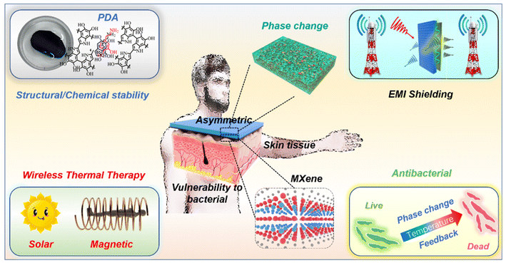
In this regard, we fabricated a bilayer asymmetric phase change composite (PCC) with a MXene@polydopamine (MXene@PDA) layer and a phase change layer (Fig. 1). The asymmetric structure could adjust the EMI shielding efficiency of the PCC as high as 54.5 dB and the PDA could improve the structural/chemical stability of the MXene layer. In addition, the asymmetric structure endows the PCC with excellent wireless thermal therapy performance due to enhanced light-to-thermal conversion and efficient magnetic-to-thermal conversion, which could maintain a considerable temperature. As a result, the combination of the MXene@PDA layer and the phase change layer exhibited great potential to enhance the antibacterial performance, revealing great value in the application of personal thermal therapy. Overall, the work provides new insights into the fabrication of advanced composites and the obtained PCCs show great practical application potential on varying occasions.
2. Results and discussion
2.1 Fabrication of asymmetric PCCs
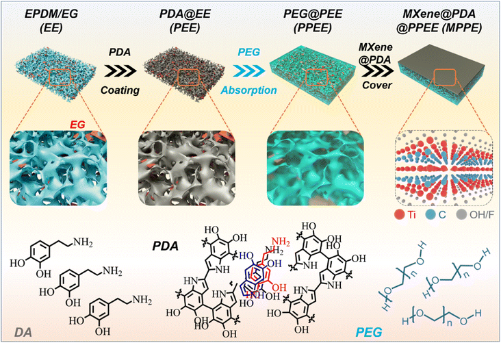
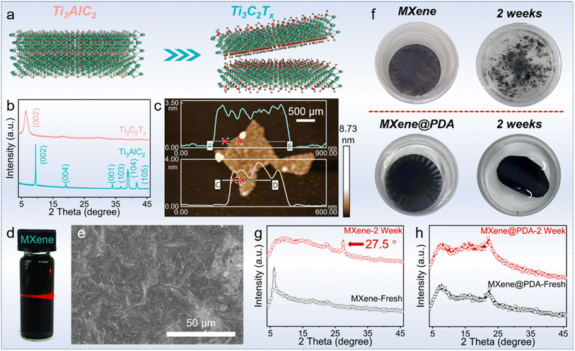
The fabrication of asymmetric PCCs entailed the development of a hydrophilic aerogel, followed by the absorption of PEG and coating with a MXene@PDA layer (Fig. 2).The MXene@PDA layer was fabricated by high-quality MXene@PDA dispersion via a vacuum filtration approach.23 The successful synthesis of the high-quality MXene dispersion was verified by X-ray diffraction (XRD), AFM, and the Tyndall effect. As reported, the selective removal of Al layers from the Ti3AlC2 MAX phase with a LiF/HCl solution yields clay-like unexfoliated MXene (Fig. 3a).24 The removal of Al layers was proved by the leftward shifted (002) peak observed by XRD characterization (Fig. 3b), in which the (002) peak appeared at 9.5° before the exfoliation and shifted to 6.4° after the exfoliation.25 Simultaneously, the presence of few-layer MXene nanosheets was proved by the AFM characterization and the corresponding height profiles, in which the average heights of MXene nanosheets range from 2.73 to 2.94 nm (Fig. 3c).26 In addition, a bright “path” in the MXene dispersion can be observed from the direction perpendicular to the incident light (Fig. 3d), revealing that the size of nano-particles in the dispersion ranges from 1 to 100 nm.27 These results demonstrate that a high-quality MXene dispersion was synthesized.
As the MXene is prone to be oxidized, the PDA was combined with MXene to enhance the structural and chemical stability of MXene.28 The MXene–PDA dispersion was successfully produced and proved by FTIR characterization (Fig. S1†), then MXene@PDA was co-vacuum filtered to produce a thin film which was observed to have a continuous and smooth surface by SEM observation (Fig. 3e). Fig. 3f demonstrates the structural stability of the MXene@PDA film. Upon being immersed in deionized water for 2 weeks, the MXene film broke into small pieces, while the MXene@PDA film remained stable. XRD analysis was conducted on the MXene (MXene-2W) and MXene@PDA (MXene@PDA-2W) films after 2 weeks of immersion (Fig. 3g and h). While the XRD curves of the MXene@PDA films hardly exhibited any changes, the characteristic peak (27.5°) of TiO2 appeared in the XRD pattern of MXene-2W, indicating that the MXene film has been oxidized and MXene@PDA has not been oxidized. It is known that MXene flakes are prone to be oxidized in either humid air or aqueous environments.29 The structural and chemical stabilities of MXene@PDA play a vital part in long-term applications concerning ambient environments, and addressing the oxidation behavior of MXene has been a critical issue. In this work, the introduction of PDA was demonstrated to increase the oxidation and structural stability of Ti3C2Tx MXene film, revealing its great potential on varying occasions.
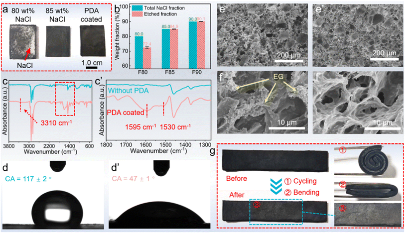
Obtaining a high-quality MXene@PDA film, the phase change layer was produced by the template method and vacuum impregnation method. A NaCl template was utilized to create expanded graphite (EG)/ethylene propylene diene monomer (EPDM) (EE) foams, wherein the NaCl content significantly impacted the structure of the resulting foam (Fig. 4a).30 As demonstrated, when an 80.0 wt% NaCl component was introduced into the EE composites, complete etching of NaCl was not feasible, resulting in visible residues on the surface. Conversely, when the NaCl content was increased to 85%, no NaCl residue was observed, signifying the successful removal of the NaCl component by water. The results were further validated via weight characterization (Fig. 4b). Specifically, when an 80 wt% NaCl content was used in the EE composites, only 72.4 wt% of NaCl was removed through the process. However, as the NaCl content increased beyond 85.0 wt%, complete removal of NaCl was achievable. These disparities originate from the fact that a high NaCl weight fraction fosters the formation of a continuous phase in the EE foam, thereby enabling the complete etching of NaCl through the water. Conversely, low NaCl weight fractions result in the formation of island phases surrounded by EPDM and EG, which resist the etching process.31
As the porous EE foam was successfully developed with 85.0 wt% NaCl, the EE foam was subsequently coated with PDA to improve its hydrophilicity.32,33 The presence of PDA creates numerous hydrophilic sites such as –OH, –NH–, and –NH2 (Fig. 2), which significantly improve the hydrophilicity of EE foam. After 24 hours of dopamine (DA) polymerization in a buffer of pH = 8.5, the successful coating of PDA on the EE foam was confirmed by Fourier transform infrared (FTIR) spectroscopy, contact angle testing, and scanning electron microscopy (SEM). Compared to the FTIR spectra of EE foam before undergoing DA polymerization, the FTIR spectra of the PDA-coated EE foam (PEE) demonstrated three new signals at 1530, 1595, and 3310 cm−1 (Fig. 4c). These signals correspond to the shearing vibration of N–H, stretching vibration of the aromatic ring and bending vibration of N–H, and stretching vibration of phenolic O–H and N–H, respectively, all of which belong to the PDA coatings.34 The result indicated the successful PDA coating on the EE foam. The contact angle tests simultaneously revealed the PDA coating on the foam as the hydrophilicity of the PEE foam has been significantly improved (Fig. 4d). Prior to the PDA coating, EE foam displayed a contact angle of 117° due to the hydrophobic nature of both EPDM and EG. After the DA polymerization, the contact angle decreased to 47°. Besides, the microstructure observation indicated the surface change caused by the PDA coating on the foam (Fig. 4e and f). There are plenty of EG particles on the surface of EE foam, whereas the surface of PEE foam becomes smoother and the EG nanoparticles could not be observed after the PDA coating. Additionally, the microstructure characterization revealed the interconnected porous structure of PEE foam. With the vulcanized EPDM constructing the skeleton and the EG dispersed in the EPDM skeleton, the obtained PDA-coated foam maintains excellent flexibility (Fig. 4g). The foam could be half-bent and rolled into a ring without brittle failures, and moreover the PEE foam could recover its initial shape without any deformation.
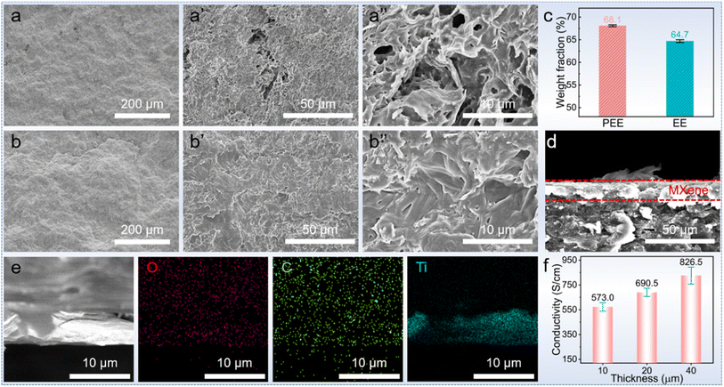
The above results revealed the exceptional shape stability of the foam and its great potential to act as a holding matrix for phase change materials. Coupled with the successful PDA coating to facilitate the adhesion of hydrophilic substances, the PDA-coating foam shows an improved capacity to absorb polyethylene glycol (PEG). SEM images show that there is a visible difference in PEG absorption performance between the uncoated foam (EE) and PDA-coated foam (PEE) (Fig. 5a): there are plenty of pores existing in the EE skeleton-based PCC, while the PDA-coating PEG-based (PPEE) PCC shows a more even surface and there are no pores in the morphology after the PEG impregnation process (Fig. 5b). The PEG capacity simultaneously demonstrates the trend: the PDA-coated foam demonstrates a higher PEG absorption capacity of 68.1 wt% compared to the 64.7 wt% of the uncoated foam (Fig. 5c). This difference arises due to the hydrophilic nature of PEG, which can well interact with the hydrophilic PDA-coated foam through hydrogen bonding, capillary force, and van der Waals forces.35 In contrast, the uncoated foam can only absorb PEG through capillary force and van der Waals forces, leading to numerous defects due to the hydrophobic nature of the EPDM and EG.36 The capacity improvement leading to fewer defects in the PCCs is beneficial to thermal energy storage and mechanical properties, which are vital to practical applications.
To obtain the PCC with improved PEG impregnation ratio, the MXene@PDA layer was coated on the PCC (Fig. 5d). Since both the PEG and PDA-coated foam are hydrophilic, the PPEE facilitates the adhesion of the MXene@PDA layer. The MXene was successfully coated and formed a continuous layer with numerous parallel sheets on the surface of PPEE to develop MXene-based PPEE (MPPE) PCCs (Fig. 5d and S2†). In addition, the MXene layer well adheres to the PPEE, and no defects are observed. EDS mapping was simultaneously conducted to verify the distribution of the MXene (Fig. 5e). While the C and O elements are homogeneously dispersed in the morphology, the Ti element disperses in a continuous layer, demonstrating that the MXene@PDA layer forms a continuous conductive layer and tightly adheres to the PDA-coated foam. Additionally, the obtained MPPE PCCs show high entropy which is characterized by DSC (Fig. S3 and Table S1†). All of the MPPE PCCs have latent heat above 100 J g−1, which significantly contributes to personal thermal comfort.37 Besides, the conductivity of the obtained composites with MXene@PDA thickness of 10, 20, and 40 μm is 573.0, 690.5, and 826.5 cm−1, respectively, which are remarkable values (Fig. 5f).
2.2 Asymmetric EMI shielding efficiency of PCCs
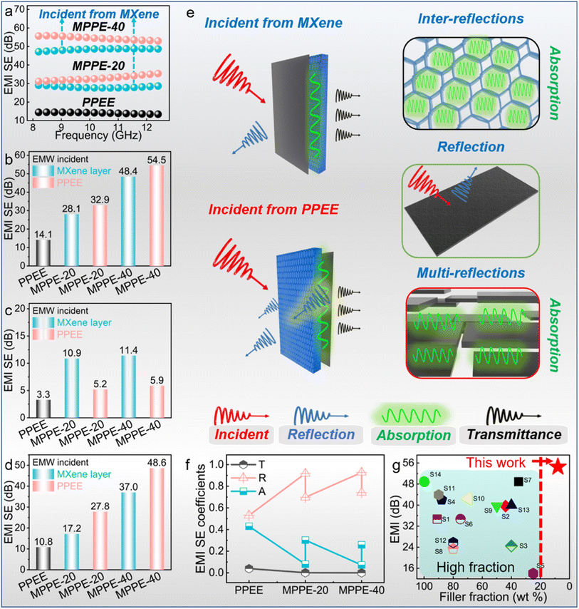
Owing to the high electrical conductivity of MXene@PDA and asymmetric structure, the PCCs exhibit unique EMI shielding performance and reveal some new insights into the development of EMI shielding materials. The EMI shielding performances of MPPE-20 and MPPE-40 with the MXene thicknesses of 20 and 40 μm were evaluated (Fig. 6a).The scattering parameters including S11 and S21 were recorded to calculate the coefficients (reflectivity: R; transmissivity: T; absorptivity: A; SER: reflection shielding efficiency; SEA: absorption shielding efficiency; SET: total shielding efficiency) using the following equations (eqn (1)–(6)):38–40
| R = |S11|2 | (1) |
| T = |S21|2 | (2) |
| A = 1 − R − T | (3) |
SER = −10![[thin space (1/6-em)]](https://www.rsc.org/images/entities/char_2009.gif) log(1 − R) log(1 − R) | (4) |
 | (5) |
| SET = SER + SEA | (6) |
The PPEE PCC shows an EMI shielding efficiency of 14.1 dB (Fig. 6b). For the EMWs incident from the MXene layer, the EMI shielding efficiencies of MPPE-20 and MPPE-40 are 28.1 and 48.4 dB, respectively. Interestingly, remarkable differences are observed in the EMI shielding performance as the incidence direction of the EMWs changed. Specifically, when the EMWs are incident on the PPEE side, the MPPE-20 and MPPE-40 show EMI shielding efficiencies of 32.9 dB and 54.4 dB, respectively. The EMI shielding efficiency is found to improve with increasing thickness of the MXene layer in the same direction. Moreover, the EMI shielding efficiencies for EMWs incident from the PPEE side are consistently higher than those of EMWs incident from the MXene layer.
SER and SEA were calculated to reveal the effect of incident EMW direction. On one hand, the SER slightly increases when the MXene thickness increases (Fig. 6c). For the EMWs incident from the MXene layer, the SER of MPPE-20 and MPPE-40 are 10.9 dB and 11.4 dB, respectively, which surpass those of EMWs incident on the PPEE side (5.2 dB and 5.9 dB for MPPE-20 and MPPE-40, respectively). On the other hand, the SEA increases significantly when the MXene thickness increases (Fig. 6d). It can be visually seen that higher SEA values are achieved for the EMWs incident from the PPEE side.
As the EMW incidence direction notably influences the EMI shielding performances of the asymmetric PCCs, the EMW transmittance processes from different sides are illustrated (Fig. 6e). When the EMWs are incident from the MXene side, some of the EMWs are reflected to the air due to the electrical conductivity mismatch between the air and MXene layer.41,42 The remaining EMWs would be transformed into heat in the form of microcurrent flow as they pass the MXene layer with numerous parallel MXene nanosheets (Fig. S2†), which causes numerous reflections and absorptions.43,44 Then the EMWs would enter the PPEE layer with an interconnected EPDM/EG skeleton, which would result in plenty of inter-reflections and absorption, and finally the surviving EMWs transmit from the PCCs.45 In contrast, the EMWs incident from the PPEE side first need to experience inter-reflection and absorption caused by the interconnected EPDM/EG skeleton. Then the EMWs undergo reflection at the interface of PPEE and MXene layers caused by the electrical conductivity mismatch.46,47 The remaining EMWs are reflected multiple times between the parallel MXene nanosheets and finally transmit from the PCCs.48
As demonstrated by the SEA and SER values, when the EMWs are incident from the PPEE layer, although the reflection (5.2 and 5.9 dB for MPPE-20 and MPPE-40, respectively) is weakened due to the low electrical conductivity of PPEE, the absorption (27.8 and 48.6 dB for MPPE-20 and MPPE-40, respectively) is significantly enhanced because most reflected EMWs are absorbed by the PPEE layer. Consequently, the EMI shielding efficiency (32.9 and 54.5 dB for MPPE-20 and MPPE-40, respectively) is notably improved. Conversely, when the EMWs are incident upon the MXene layer, there is an opposite trend with an increase in reflection (10.9 and 11.4 dB for MPPE-20 and MPPE-40, respectively) and a reduction (17.2 and 37.0 dB for MPPE-20 and MPPE-40, respectively) in absorption. Therefore, the change in EMI shielding efficiency is attributed to the differences in reflection and absorption between the PPEE and MXene layers.
The reflectivity and absorptivity simultaneously support these conclusions. The obtained PCCs showed high reflectivity (R > 0.6) and low absorptivity (A < 0.4) (Fig. 6f), and the values of R and A change significantly in response to the change of EMW incidence direction.49 This finding reveals that the EMI shielding performances of asymmetric PCCs could be fine-tuned by adjusting the incidence direction of EMWs. Additionally, the obtained PCCs exhibit high EMI shielding efficiency with a low fraction of fillers (Fig. 6g and Table S2†), illustrating superior effectiveness in EMI shielding. Overall, the present study unveils novel findings that differentiate it from prior research by showing that the asymmetric structure can enhance the EMI shielding performances of PCCs by direction adjustment. The development of the asymmetric structure could be a general approach for advancing composites with superior performance in areas like EMI shielding, reflecting the broad potential of asymmetric PCCs in practical applications.50
2.3 Wireless thermal therapy performances of PCCs
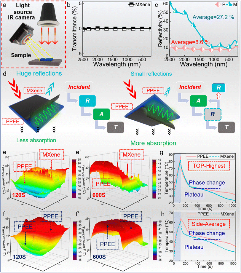
Light and magnetic input could be ideal alternative energy sources for wireless thermal therapy as the light and magnetic field do not need to be in direct contact with the skin, and thermal therapy based on wireless heat input shows great potential.51,52 In our work, both the light-to-thermal and magnetic-to-thermal conversions of PCCs were characterized and the PCCs exhibit high efficiency in maintaining considerable temperature for thermal therapy and antibacterial properties.The obtained asymmetric PCCs display different light absorption properties from traditional multilayered and sandwich composites. Specifically, the light incident from different directions shows totally changed absorption performances. When light is incident from the MXene side, the PCC shows a higher reflectivity in the whole wavenumber range and the average value is 27.2% while the light reflectivity from the PPEE is only 8.6% (Fig. 7c). As eqn (7) shows,
| Input = reflection + absorption + transmittance | (7) |
While almost no light is transmitted from the PCCs because of the excellent light-shielding ability of the MXene layer (Fig. 7b), more light incident from the MXene layer would be reflected into the air and less light will be absorbed by the PCCs. Conversely, as the light is incident from the PPEE, less light will be reflected, leading to much light absorption. The asymmetric structure could boost light absorption performance by adjusting the light direction, showing more potential compared with the traditional sandwich and multilayered structured composites.
The light-to-thermal conversion was simulated further (Fig. 7a). Initially, the PCC first experiences a rapid temperature increase. This is followed by a rapid temperature decrease, and the temperature remains stable for a considerable period due to the phase change process.53 Then the temperature gradually decreases to the ambient temperature. The temperature increase curve hardly shows any decay because the PCC is charged rapidly, revealing the excellent light absorption ability of PCCs. The in-time images of temperature distribution concurrently demonstrate the better light absorption ability adjusted by the asymmetric structure. When the light is incident from the MXene layer, the upper surface is the MXene layer and the side face is the PPEE layer (Fig. 7e). At 120 seconds, the temperature of the MXene layer surpasses that of the PPEE layer because the light is transformed into heat in the MXene layer and the heat transfers to the PPEE layer. At 600 seconds, the temperature of the PPEE layer is higher than that of the MXene layer, triggered by the release of heat stored in the PPEE layer during cooling. After the light direction changes to incident from the PPEE layer, both the upper surface and side face are PPEE, whose temperatures are always higher than those of PCCs with light incident from the PPEE side at 120 and 600 seconds (Fig. 7f). The divergence is caused by the diverse light absorption performances between MXene and PPEE. The corresponding light absorption processes are depicted in Fig. 7d. Given that the light contacts the MXene layer directly, it reflects off into the air, leading to serious energy loss. However, when the light initially exposes the PPEE layer, only a fraction of it is reflected to the air, and most of the reflected light by MXene is consequently absorbed by the PPEE layer, thereby yielding an optimized light absorption efficiency.
The temperature curves provide evidence supporting our conclusion (Fig. 7g and h). The maximum and average temperatures of MPPE simultaneously demonstrate the trend. When the light is incident from the PPEE layer, both the upper and side surfaces of the MPPE exhibit elevated temperatures throughout the process. Besides, the PCCs display exceptional temperature maintenance performance, as evident from the presence of notable plateaus in the curves. Impressively, after only 120 seconds of heating, the PCC maintained a temperature above 43 °C for over 600 seconds, highlighting the outstanding performance and efficiency of the phase change process in maintaining the desired temperature.
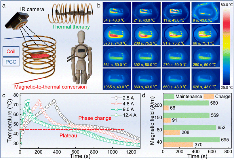
In addition to its notable light-to-thermal conversion, the PCC exhibits remarkable magnetic-to-thermal conversion despite its lack of magnetic composition (Fig. 8a). When subjected to a magnetic field, the PCC generates considerable heat through periodic electron motion stemming from either Néel relaxation or Brownian relaxation,54 facilitated by its highly conductive MXene layer. By reaching an average temperature of 75 °C, the magnetic field was cut off. At a magnetic field of 2.5/4.8/9.0/12.4 A, the PCCs were fast heated to about 75 °C in 370, 208, 91, and 66 seconds, respectively (Fig. 8b). The charging time reduces with the increase of magnetic field strength. Then the temperature rapidly decreases until the PCCs begin to experience phase change processes. The PCCs were found to exhibit excellent temperature maintenance performances. From 50 °C to 43 °C, the PCC spends 504, 468, 390, and 376 seconds, respectively. The temperature curves could more clearly show the trend (Fig. 8c). When the magnetic field increases, the temperature-increase rate is boosted. Besides, all of the curves exhibit obvious plateaus of more than 300 seconds, which is caused by the phase change process. The PCCs last 595, 652, 569, and 560 seconds from 75 °C to 43 °C in the magnetic field of 2.5/4.8/9.0/12.4 A, respectively (Fig. 8d). For a charge of 66 seconds, the temperature could remain above 43 °C for more than 560 seconds, showing excellent thermal therapy potential in practical applications.
2.4 Temperature-dependent antibacterial performance
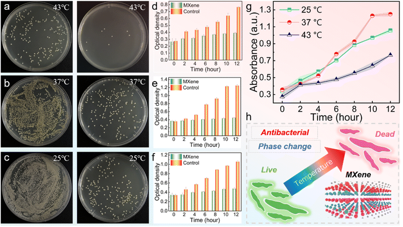
Temperature plays a critical role in the growth and survival of bacteria.55 Given the excellent temperature maintenance abilities of PCCs (effective above 43 °C) under light and magnetic fields, the PCCs possess substantial potential for wireless thermal management and antibacterial activity. The antibacterial effectiveness of MXene against S. aureus at varying temperatures (25, 37, and 43 °C) was assessed by evaluating the growth curve and cell viability. Following co-incubation of S. aureus (107 CFU mL−1) with MXene (0.5 mg mL−1) for 60 minutes, laser irradiation was employed to raise the mixture's temperature to 25, 37, and 43 °C, respectively, and kept for 5 minutes. Subsequently, the mixture was reincubated on agar plates at 37 °C for 18 hours, and typical photographs of bacterial colonies treated with PBS and MXene are shown in Fig. 9a.At 25 °C and 37 °C, the S. aureus in control groups display high activity as numerous colonies are surviving, while the S. aureus at 43 °C exhibit low activity with a significantly reduced number of S. aureus. The number of colonies shows a reducing trend with increasing temperature, implying that the temperature increase could hinder the growth of S. aureus.56 Besides, at each temperature, the number of colonies in the MXene-treated groups was significantly reduced compared to the control groups, indicating that MXene has good antibacterial activity on S. aureus. Meanwhile, the number of colonies in the MXene-treated group reduced obviously as the temperature increased. These results suggest that the temperature increase could further improve the antibacterial activity of MXene to achieve a better bactericidal effect.57 The proliferation of S. aureus was simultaneously assessed by OD600 values (Fig. 9b). At all the assessed temperatures (25, 37, and 43 °C), the MXene-treated groups always yielded lower OD600 values than the control groups. In addition, the OD600 value reduced significantly from 37 °C to 43 °C (Fig. 9c). The results suggest that MXene has excellent antibacterial activity and the considerable temperature could further enhance the antibacterial performance of MXene. Coupled with the excellent light-to-thermal and magnetic-to-thermal conversion to keep PCCs at a considerable temperature, the obtained PCCs show tremendous potential in thermal therapy applications (Fig. 9d).
3. Conclusion
A series of layered asymmetric PCCs with anti-oxidation MXene@PDA and phase change layers were fabricated. The asymmetric structure could adjust the EMI shielding efficiency as high as 54.5 dB. Simultaneously, the PCCs exhibited improved light-to-thermal conversion and excellent magnetic-to-thermal conversion, which reveal high efficiencies in maintaining a considerable temperature. As the experimental results show that considerable temperature could assist the antibacterial performances and the MXene has excellent antibacterial activity, the obtained PCCs demonstrated great potential in the application of thermal comfort and antibacterial applications. Overall, the work gives new insights into the fabrication of advanced composites with improved EMI shielding efficiency and light-to-thermal conversion by asymmetric design, and the obtained PCCs display great practical application prospects in terms of varying demanding occasions.4. Experimental
4.1 Materials
The EPDM (4820P) was obtained from Dow Chemical Company (USA). Stearic acid (SA), zinc oxide (ZnO), PEG (Mn = 4000), dopamine hydrochloride (DA), hydrogen chloride (HCl), lithium chloride (LiCl), lithium fluoride (LiF), and tris(hydroxymethyl)aminomethane (Tris) were purchased from Aladdin Reagent (Shanghai, China). MAX powder (Ti3AlC2, 200 mesh) was supplied by Jilin 11 Technology Co., Ltd. N-Cyclohexyl-2-benzothiazole sulfonamide (CBS) was purchased from Shanghai Chengjin Chemical Co., Ltd (China). Sulfur was purchased from Lianyungang Lanxing Industrial Technology Co., Ltd (China). Phosphate buffered saline (PBS) and Luria–Bertani broth (LB) were purchased from Sigma-Aldrich.4.2 Fabrication of EPDM/EG (EE) foam
EPDM/EG foams were obtained by two-step melt blending and water-soluble etching. The EPDM/EG composite was obtained by melt blending in a self-developed biaxial eccentric rotor extruder (BERE) based on elongational rheology as reported in our previous work.58 And the ratios of curing agents are the same as reported in our previous work. This was followed by melt blending with NaCl, whose weight fractions are 80/85/90%. The composites denoted as F80, F85, and F90 were vulcanized at 180 °C and at a pressure of 10 MPa for 30 minutes. The obtained composites were sonicated in water for 24 hours to remove water-soluble NaCl and to acquire the corresponding EE foam.4.3 Fabrication of PDA-coated foam (PEE), PEG-based (PPEE) PCCs, and MXene-based (MPPE) PCCs
Ti3C2Tx MXene was synthesized through the selective chemical etching method.59 The typical preparation process is to mix 40 mL concentrated 9 M HCl and 3.1128 g LiF in a polytetrafluoroethylene beaker, which was stirred to generate an ionic solution. Then, 2.0 g MAX Ti3AlC2 powder was slowly added in and reacted at 38 °C for 48 hours. Afterward, the resultant slurry was washed with 1 M HCl, 1 M LiCl, and deionized water until its pH reached 7.0. Deionized water (50 mL) was added to the sediment and then the mixture was ultrasonicated for 60 min under a N2 flow in an ice bath for exfoliation of the MXene sheets. The supernatant, a uniform Ti3C2Tx MXene colloidal dispersion, was collected by centrifugation at 3500 rpm. Then the MXene and dopamine at a weight ratio of 1![[thin space (1/6-em)]](https://www.rsc.org/images/entities/char_2009.gif) :
:![[thin space (1/6-em)]](https://www.rsc.org/images/entities/char_2009.gif) 1 were added into a Tris buffer solution (pH = 8.5) and then stirred for 24 hours to synthesize MXene@PDA, which was extracted by centrifugation (12
1 were added into a Tris buffer solution (pH = 8.5) and then stirred for 24 hours to synthesize MXene@PDA, which was extracted by centrifugation (12![[thin space (1/6-em)]](https://www.rsc.org/images/entities/char_2009.gif) 000 rpm, 10 min) and washed with deionized water 3 times. The MXene film and MXene@PDA film were obtained via vacuum filtration.
000 rpm, 10 min) and washed with deionized water 3 times. The MXene film and MXene@PDA film were obtained via vacuum filtration.
The EE foam was immersed into a Tris buffer solution (pH = 8.5), in which 5.0 mg per mL DA was added and self-polymerized for 24 hours under stirring. After the reaction, the samples were washed with deionized water under sonication twice and then freeze-dried to remove all the deionized water.
The PPEE PCC was prepared via the vacuum impregnation method. The PEE films were dipped in the melted PEG (Mn = 4000), and then put into a vacuum oven for impregnation, and the process was left to occur at 80 °C for 24 hours. Afterward, the films were put on filter paper and then placed in the oven (80 °C) for another 4 hours to remove the excess PEG on the surface. The same impregnation process was carried out on the EE foam for comparison.
Different thicknesses (10/20/40 μm) of MXene films were prepared via a vacuum filtration process. Then the MXene layers with 20 and 40 μm thicknesses were coated on the PPEE films at 80 °C to obtain MPPE-20 and MPPE-40.
4.4 Antibacterial test of MXene
The S. aureus ATCC 6538 strain was cultured in an LB medium and harvested during the exponential growth phase through centrifugation for subsequent experiments. Bacterial concentration was monitored at 600 nm through optical density (OD) measurement using a spectrophotometer. The initial bacterial concentration was adjusted to 2 × 10⁸ CFU mL−1 before experimentation. To investigate the antibacterial effect of the MXene on S. aureus, the MXene dispersion (concentration of 0.5 mg mL−1) was mixed with bacterial cultures (107 CFU mL−1) and maintained at 25, 37, and 43 °C for 5 minutes, followed by incubation for 30 minutes. Then, 100 μL of each bacterial suspension was plated on LB agar plates and incubated at 37 °C for 18 hours. Additionally, bacterial cultures in the logarithmic growth phase were diluted to a concentration of 105 CFU mL−1 and treated with 10 μL of the MXene (final concentration of 0.1 mg mL−1) for cocultivation. The PBS group was used as the control group (n = 5). Bacterial growth was continuously monitored at 600 nm for 12 hours, and the growth of each bacterial group was analyzed and evaluated.Author contributions
X. Hu, X. L., and J. Q. conceived the project. X. Hu, B. Q., and B. A. performed the experiments. X. Hu and B. Q. analyzed the results. B. Q., M. S., L. S., X. Huang, and H. W. provided useful suggestions for this work. X. Hu wrote the manuscript. X. Hu, X. L., and J. Q. critically discussed the results and reviewed the manuscript.Conflicts of interest
The authors declare that they have no known competing financial interests or personal relationships that could have appeared to influence the work reported in this paper.Acknowledgements
This work was supported by the National Natural Science Foundation of China (No. 52173036, 52073107), the National Key Technology R&D Program of China (Grant No. 2020YFB1709301, 2020YFB1709304 and 2021YFC2101705), and the Fundamental Research Funds for the Central Universities (Grant 2021XXJS035).References
- D. P. Dubal, N. R. Chodankar, D.-H. Kim and P. Gomez-Romero, Towards Flexible Solid-State Supercapacitors for Smart and Wearable Electronics, Chem. Soc. Rev., 2018, 47(6), 2065–2129, 10.1039/c7cs00505a.
- L. Bi, Z. Yang, L. Chen, Z. Wu and C. Ye, Compressible AgNWs/Ti3C2Tx MXene Aerogel-Based Highly Sensitive Piezoresistive Pressure Sensor as Versatile Electronic Skins, J. Mater. Chem. A, 2020, 8(38), 20030–20036, 10.1039/d0ta07044k.
- X. Hu, B. Quan, C. Zhu, H. Wen, M. Sheng, S. Liu, X. Li, H. Wu, X. Lu and J. Qu, Upgrading Electricity Generation and Electromagnetic Interference Shielding Efficiency via Phase-Change Feedback and Simple Origami Strategy, Adv. Sci., 2023, 10(14), 2206835, DOI:10.1002/advs.202206835.
- G. H. Wang, S. J. H. Ong, Y. Zhao, Z. J. C. Xu and G. B. Ji, Integrated Multifunctional Macrostructures for Electromagnetic Wave Absorption and Shielding, J. Mater. Chem. A, 2020, 8(46), 24368–24387, 10.1039/d0ta08515d.
- K. Zhang, G.-H. Li, L.-M. Feng, N. Wang, J. Guo, K. Sun, K.-X. Yu, J.-B. Zeng, T. Li, Z. Guo and M. Wang, Ultralow Percolation Threshold and Enhanced Electromagnetic Interference Shielding in Poly(L-Lactide)/Multi-Walled Carbon Nanotube Nanocomposites with Electrically Conductive Segregated Networks, J. Mater. Chem. C, 2017, 5(36), 9359–9369, 10.1039/c7tc02948a.
- P. Song, B. Liu, C. Liang, K. Ruan, H. Qiu, Z. Ma, Y. Guo and J. Gu, Lightweight, Flexible Cellulose-Derived Carbon Aerogel@Reduced Graphene Oxide/PDMS Composites with Outstanding EMI Shielding Performances and Excellent Thermal Conductivities, Nano-Micro Lett., 2021, 13(91), 1–17, DOI:10.1007/s40820-021-00624-4.
- S. Gong, X. Sheng, X. Li, M. Sheng, H. Wu, X. Lu and J. Qu, A Multifunctional Flexible Composite Film with Excellent Multi-Source Driven Thermal Management, Electromagnetic Interference Shielding, and Fire Safety Performance, Inspired by a “Brick–Mortar” Sandwich Structure, Adv. Funct. Mater., 2022, 32(26), 2200570, DOI:10.1002/adfm.202200570.
- X. Hu, C. Zhu, B. Quan, M. Sheng, H. Wu, X. Lu and J. Qu, Engineering Robust Multifunctional Composites with Enhanced Electromagnetic Interference Shielding and All-Weather Thermal Management Capability via Simple Layer-by-Layer Assembly, Chem. Eng. J., 2022, 446, 137423, DOI:10.1016/j.cej.2022.137423.
- B. Dai, X. Li, T. Xu and X. Zhang, Radiative Cooling and Solar Heating Janus Films for Personal Thermal Management, ACS Appl. Mater. Interfaces, 2022, 14, 18877–18883, DOI:10.1021/acsami.2c01370.
- P.-C. Hsu, C. Liu, A. Y. Song, Z. Zhang, Y. Peng, J. Xie, K. Liu, C.-L. Wu, P. B. Catrysse, L. Cai, S. Zhai, A. Majumdar, S. Fan and Y. Cui, A Dual-Mode Textile for Human Body Radiative Heating and Cooling, Sci. Adv., 2017, 3, e1700895, DOI:10.1126/sciadv.1700895.
- Q. Zhang, Y. Wang, Y. Lv, S. Yu and R. Ma, Bioinspired Zero-Energy Thermal-Management Device Based on Visible and Infrared Thermochromism for All-Season Energy Saving, Proc. Natl. Acad. Sci. U. S. A., 2022, 119(38), e2207353119, DOI:10.1073/pnas.2207353119.
- X. Hu, H. Wu, X. Lu, S. Liu and J. Qu, Improving Thermal Conductivity of Ethylene Propylene Diene Monomer/Paraffin/Expanded Graphite Shape-Stabilized Phase Change Materials with Great Thermal Management Potential via Green Steam Explosion, Adv. Compos. Hybrid Mater., 2021, 4, 478–491, DOI:10.1007/s42114-021-00300-6.
- D. Huang, Z. Wang, X. Sheng and Y. Chen, Bio-Based MXene Hybrid Aerogel/Paraffin Composite Phase Change Materials with Superior Photo and Electrical Responses toward Solar Thermal Energy Storage, Sol. Energy Mater. Sol. Cells, 2023, 251, 112124, DOI:10.1016/j.solmat.2022.112124.
- Z. Li, Z. Zhuang, F. Lv, H. Zhu, L. Zhou, M. Luo, J. Zhu, Z. Lang, S. Feng, W. Chen, L. Mai and S. Guo, The Marriage of the FeN4 Moiety and MXene Boosts Oxygen Reduction Catalysis: Fe 3d Electron Delocalization Matters, Adv. Mater., 2018, 30(43), 1803220, DOI:10.1002/adma.201803220.
- B. Cheng and P. Wu, Scalable Fabrication of Kevlar/Ti3C2Tx MXene Intelligent Wearable Fabrics with Multiple Sensory Capabilities, ACS Nano, 2021, 15(5), 8676–8685, DOI:10.1021/acsnano.1c00749.
- H. Tang, W. Li, L. Pan, C. P. Cullen, Y. Liu, A. Pakdel, D. Long, J. Yang, N. McEvoy, G. S. Duesberg, V. Nicolosi and C. Zhang, In Situ Formed Protective Barrier Enabled by Sulfur@Titanium Carbide (MXene) Ink for Achieving High-Capacity, Long Lifetime Li-S Batteries, Adv. Sci., 2018, 5(9), 1800502, DOI:10.1002/advs.201800502.
- M. Han, C. E. Shuck, R. Rakhmanov, D. Parchment, B. Anasori, C. M. Koo, G. Friedman and Y. Gogotsi, Beyond Ti3C2Tx: MXenes for Electromagnetic Interference Shielding, ACS Nano, 2020, 14(4), 5008–5016, DOI:10.1021/acsnano.0c01312.
- Y. Wang, R. Liu, J. Zhang, M. Miao and X. Feng, Vulcanization of Ti3C2Tx MXene/Natural Rubber Composite Films for Enhanced Electromagnetic Interference Shielding, Appl. Surf. Sci., 2021, 546, 149143, DOI:10.1016/j.apsusc.2021.149143.
- M. Miao, R. Liu, S. Thaiboonrod, L. Shi, S. Cao, J. Zhang, J. Fang and X. Feng, Silver Nanowires Intercalating Ti3C2Tx MXene Composite Films with Excellent Flexibility for Electromagnetic Interference Shielding, J. Mater. Chem. C, 2020, 8(9), 3120–3126, 10.1039/c9tc06361g.
- V. M. H. Ng, H. Huang, K. Zhou, P. S. Lee, W. Que, J. Z. Xu and L. B. Kong, Recent Progress in Layered Transition Metal Carbides and/or Nitrides (MXenes) and Their Composites: Synthesis and Applications, J. Mater. Chem. A, 2017, 5(7), 3039–3068, 10.1039/c6ta06772g.
- K. Rasool, M. Helal, A. Ali, C. E. Ren, Y. Gogotsi and K. A. Mahmoud, Antibacterial Activity of Ti(3)C(2)Tx MXene, ACS Nano, 2016, 10(3), 3674–3684, DOI:10.1021/acsnano.6b00181.
- Y. Sun, D. Jin, Y. Sun, X. Meng, Y. Gao, Y. Dall'Agnese, G. Chen and X. F. Wang, G-C3N4/Ti3C2Tx (MXenes) Composite with Oxidized Surface Groups for Efficient Photocatalytic Hydrogen Evolution, J. Mater. Chem. A, 2018, 6(19), 9124–9131, 10.1039/c8ta02706d.
- M. Q. Wu, S. Wu, Y. F. Cai, R. Z. Wang and T. X. Li, Form-Stable Phase Change Composites: Preparation, Performance, and Applications for Thermal Energy Conversion, Storage and Management, Energy Storage Mater., 2021, 42, 380–417, DOI:10.1016/j.ensm.2021.07.019.
- Y. Du, H. Huang, X. Hu, S. Liu, X. Sheng, X. Li, X. Lu and J. Qu, Melamine Foam/Polyethylene Glycol Composite Phase Change Material Synergistically Modified by Polydopamine/MXene with Enhanced Solar-to-Thermal Conversion, Renewable Energy, 2021, 171, 1–10, DOI:10.1016/j.renene.2021.02.077.
- B. Quan, J. Wang, Y. Li, M. Sui, H. Xie, Z. Liu, H. Wu, X. Lu and Y. Tong, Cellulose Nanofibrous/MXene Aerogel Encapsulated Phase Change Composites with Excellent Thermal Energy Conversion and Storage Capacity, Energy, 2023, 262, 125505, DOI:10.1016/j.energy.2022.125505.
- Y. Luo, Y. Xie, H. Jiang, Y. Chen, L. Zhang, X. Sheng, D. Xie, H. Wu and Y. Mei, Flame-Retardant and Form-Stable Phase Change Composites Based on MXene with High Thermostability and Thermal Conductivity for Thermal Energy Storage, Chem. Eng. J., 2021, 420, 130446, DOI:10.1016/j.cej.2021.130466.
- P. G. Abeykoon, S. P. Ward, F. Chen and D. H. Adamson, Chromatographic Approach to Isolate Exfoliated Graphene, Langmuir, 2021, 37(31), 9378–9384, DOI:10.1021/acs.langmuir.1c00917.
- H. Wu, C. Zhu, X. Li, X. Hu, H. Xie, X. Lu and J.-P. Qu, Layer-by-Layer Assembly of Multifunctional NR/MXene/CNTs Composite Films with Exceptional Electromagnetic Interference Shielding Performances and Excellent Mechanical Properties, Macromol. Rapid Commun., 2022, 43(18), 2200387, DOI:10.1002/marc.202200387.
- C. J. Zhang, S. Pinilla, N. McEyoy, C. P. Cullen, B. Anasori, E. Long, S.-H. Park, A. Seral-Ascaso, A. Shmeliov, D. Krishnan, C. Morant, X. Liu, G. S. Duesberg, Y. Gogotsi and V. Nicolosi, Oxidation Stability of Colloidal Two-Dimensional Titanium Carbides (MXenes), Chem. Mater., 2017, 29(11), 4848–4856, DOI:10.1021/acs.chemmater.7b00745.
- B. R. Thompson, T. S. Horozov, S. D. Stoyanov and V. N. Paunov, Hierarchically Structured Composites and Porous Materials from Soft Templates: Fabrication and Applications, J. Mater. Chem. A, 2019, 7(14), 8030–8049, 10.1039/C8TA09750J.
- X. Li, M. Sheng, S. Gong, H. Wu, X. Chen, X. Lu and J. Qu, Flexible and Multifunctional Phase Change Composites Featuring High-Efficiency Electromagnetic Interference Shielding and Thermal Management for Use in Electronic Devices, Chem. Eng. J., 2022, 430, 132928, DOI:10.1016/j.cej.2021.132928.
- J. L. Wang, K. F. Ren, H. Chang, S. M. Zhang, L. J. Jin and J. Ji, Facile Fabrication of Robust Superhydrophobic Multilayered Film Based on Bioinspired Poly(Dopamine)-Modified Carbon Nanotubes, Phys. Chem. Chem. Phys., 2014, 16(7), 2936–2943, 10.1039/c3cp54354d.
- B. Hu, S. Sun, B. Wu and P. Wu, Colloidally Stable Monolayer Nanosheets with Colorimetric Responses, Small, 2019, 15(5), 1804975, DOI:10.1002/smll.201804975.
- R. Xing, W. Wang, T. Jiao, K. Ma, Q. Zhang, W. Hong, H. Qiu, J. Zhou, L. Zhang and Q. Peng, Bioinspired Polydopamine Sheathed Nanofibers Containing Carboxylate Graphene Oxide Nanosheet for High-Efficient Dyes Scavenger, ACS Sustain. Chem. Eng., 2017, 5(6), 4948–4956, DOI:10.1021/acssuschemeng.7b00343.
- R. Shen, M. Weng, L. Zhang, J. Huang and X. Sheng, Biomass-Based Carbon Aerogel/Fe3O4@PEG Phase Change Composites with Satisfactory Electromagnetic Interference Shielding and Multi-Source Driven Thermal Management in Thermal Energy Storage, Composites, Part A, 2022, 163, 107248, DOI:10.1016/j.compositesa.2022.107248.
- X. Du, J. Qiu, S. Deng, Z. Du, X. Cheng and H. Wang, Alkylated Nanofibrillated Cellulose/Carbon Nanotubes Aerogels Supported Form-Stable Phase Change Composites with Improved n-Alkanes Loading Capacity and Thermal Conductivity, ACS Appl. Mater. Interfaces, 2020, 12(5), 5695–5703, DOI:10.1021/acsami.9b17771.
- X. Shen, F. Wang, Z. Mao, H. Xu, B. Wang, X. Sui and X. Feng, Biphasic Organohydrogels Based on Phase Change Materials with Excellent Thermostability for Thermal Management Applications, Chem. Eng. J., 2021, 416, 129181, DOI:10.1016/j.cej.2021.129181.
- N. Kozak, L. Matzui, L. Vovchenko, L. Kosyanchuk, V. Oliynyk, O. Antonenko, S. Nesin and Z. Gagolkina, Influence of Coordination Complexes of Transition Metals on EMI-Shielding Properties and Permeability of Polymer Blend/Carbon Nanotube/Nickel Composites, Compos. Sci. Technol., 2020, 200, 108420, DOI:10.1016/j.compscitech.2020.108420.
- S. Liao, X. Wang, X. Li, Y. Wan, T. Zhao, Y. Hu, P. Zhu, R. Sun and C. Wong, Flexible Liquid Metal/Cellulose Nanofiber Composites Film with Excellent Thermal Reliability for Highly Efficient and Broadband EMI Shielding, Chem. Eng. J., 2021, 422, 129962, DOI:10.1016/j.cej.2021.129962.
- D. Huang, Y. Chen, L. Zhang and X. Sheng, Flexible Thermoregulatory Microcapsule/Polyurethane-MXene Composite Films with Multiple Thermal Management Functionalities and Excellent EMI Shielding Performance, J. Mater. Sci. Technol., 2023, 165, 27–38, DOI:10.1016/j.jmst.2023.05.013.
- Z. Ma, S. Kang, J. Ma, L. Shao, Y. Zhang, C. Liu, A. Wei, X. Xiang, L. Wei and J. Gu, Ultraflexible and Mechanically Strong Double-Layered Aramid Nanofiber-Ti3C2Tx MXene/Silver Nanowire Nanocomposite Papers for High-Performance Electromagnetic Interference Shielding, ACS Nano, 2020, 14(7), 8368–8382, DOI:10.1021/acsnano.0c02401.
- B. Xue, Y. Li, Z. Cheng, S. Yang, L. Xie, S. Qin and Q. Zheng, Directional Electromagnetic Interference Shielding Based on Step-Wise Asymmetric Conductive Networks, Nano-Micro Lett., 2021, 14(1), 16, DOI:10.1007/s40820-021-00743-y.
- B. Sun, S. Sun, P. He, H.-Y. Mi, B. Dong, C. Liu and C. Shen, Asymmetric Layered Structural Design with Segregated Conductive Network for Absorption-Dominated High-Performance Electromagnetic Interference Shielding, Chem. Eng. J., 2021, 416, 129083, DOI:10.1016/j.cej.2021.129083.
- L. Fu, K. Li, H. Qin, J. Hou, X. Zhang, G. He, B. Liu, C. Ren and J. Chen, Sandwich Structured IPP/CNTs Nanocomposite Foams with High Electromagnetic Interference Shielding Performance, Compos. Sci. Technol., 2022, 220, 109297, DOI:10.1016/j.compscitech.2022.109297.
- Q. Wei, S. Pei, X. Qian, H. Liu, Z. Liu, W. Zhang, T. Zhou, Z. Zhang, X. Zhang, H. M. Cheng and W. Ren, Superhigh Electromagnetic Interference Shielding of Ultrathin Aligned Pristine Graphene Nanosheets Film, Adv. Mater., 2020, 32(14), e1907411, DOI:10.1002/adma.201907411.
- W. Chen, L. X. Liu, H. B. Zhang and Z. Z. Yu, Flexible, Transparent, and Conductive Ti3C2Tx MXene-Silver Nanowire Films with Smart Acoustic Sensitivity for High-Performance Electromagnetic Interference Shielding, ACS Nano, 2020, 14(12), 16643–16653, DOI:10.1021/acsnano.0c01635.
- C. Zhang, B. Anasori, A. Seral-Ascaso, S.-H. Park, N. McEvoy, A. Shmeliov, G. S. Duesberg, J. N. Coleman, Y. Gogotsi and V. Nicolosi, Transparent, Flexible, and Conductive 2D Titanium Carbide (MXene) Films with High Volumetric Capacitance, Adv. Mater., 2017, 29(36), 1702678, DOI:10.1002/adma.201702678.
- K. Qian, Q. Zhou, H. Wu, J. Fang, M. Miao, Y. Yang, S. Cao, L. Shi and X. Feng, Carbonized Cellulose Microsphere@void@MXene Composite Films with Egg-Box Structure for Electromagnetic Interference Shielding, Composites, Part A, 2021, 141, 106229, DOI:10.1016/j.compositesa.2020.106229.
- H. Zhao, J. Yun, Y. Zhang, K. Ruan, Y. Huang, Y. Zheng, L. Chen and J. Gu, Pressure-Induced Self-Interlocked Structures for Expanded Graphite Composite Papers Achieving Prominent EMI Shielding Effectiveness and Outstanding Thermal Conductivities, ACS Appl. Mater. Interfaces, 2022, 14(2), 3233–3243, DOI:10.1021/acsami.1c22950.
- U. Hwang, J. Kim, H. Sun, I.-K. Park, J. Suhr and J.-D. Nam, Aperture Control in Polymer-Based Composites with Hybrid Core-Shell Spheres for Frequency-Selective Electromagnetic Interference Shielding, J. Mater. Chem. A, 2022, 10(16), 8751–8760, 10.1039/d2ta00045h.
- H. Ma and M. Xue, Recent Advances in the Photothermal Applications of Two-Dimensional Nanomaterials: Photothermal Therapy and Beyond, J. Mater. Chem. A, 2021, 9(33), 17569–17591, 10.1039/d1ta04134g.
- H. Lin, S. Gao, C. Dai, Y. Chen and J. Shi, A Two-Dimensional Biodegradable Niobium Carbide (MXene) for Photothermal Tumor Eradication in NIR-I and NIR-II Biowindows, J. Am. Chem. Soc., 2017, 139(45), 16235–16247, DOI:10.1021/jacs.7b07818.
- S. Wu, T. Li, Z. Tong, J. Chao, T. Zhai, J. Xu, T. Yan, M. Wu, Z. Xu, H. Bao, T. Deng and R. Wang, High-Performance Thermally Conductive Phase Change Composites by Large-Size Oriented Graphite Sheets for Scalable Thermal Energy Harvesting, Adv. Mater., 2019, 31(49), 1905099, DOI:10.1002/adma.201905099.
- K. Zhou, Y. Sheng, W. Guo, L. Wu, H. Wu, X. Hu, Y. Xu, Y. Li, M. Ge and Y. Du, Biomass Porous Carbon/Polyethylene Glycol Shape-Stable Phase Change Composites for Multi-Source Driven Thermal Energy Conversion and Storage, Adv. Compos. Hybrid Mater., 2023, 6(1), 34, DOI:10.1007/s42114-022-00620-1.
- S. Nastyshyn, J. Raczkowska, Y. Stetsyshyn, B. Orzechowska, A. Bernasik, Y. Shymborska, M. Brzychczy-Włoch, T. Gosiewski, O. Lishchynskyi, H. Ohar, D. Ochońska, K. Awsiuk and A. Budkowski, Non-Cytotoxic, Temperature-Responsive and Antibacterial POEGMA Based Nanocomposite Coatings with Silver Nanoparticles, RSC Adv., 2020, 10(17), 10155–10166, 10.1039/C9RA10874B.
- X.-L. Lei, K. Cheng, Y. Li, Z.-T. Zhong, X.-L. Hou, L.-B. Song, F. Zhang, J.-H. Wang, Y.-D. Zhao and Q.-R. Xu, The Eradication of Biofilm for Therapy of Bacterial Infected Chronic Wound Based on PH-Responsive Micelle of Antimicrobial Peptide Derived Biodegradable Microneedle Patch, Chem. Eng. J., 2023, 462, 142222, DOI:10.1016/j.cej.2023.142222.
- D. Zhang, L. Huang, D.-W. Sun, H. Pu and Q. Wei, Bio-Interface Engineering of MXene Nanosheets with Immobilized Lysozyme for Light-Enhanced Enzymatic Inactivation of Methicillin-Resistant Staphylococcus Aureus, Chem. Eng. J., 2023, 452, 139078, DOI:10.1016/j.cej.2022.139078.
- H. Wu, X. Hu, X. Li, M. Sheng, X. Sheng, X. Lu and J. Qu, Large-Scale Fabrication of Flexible EPDM/MXene/PW Phase Change Composites with Excellent Light-to-Thermal Conversion Efficiency via Water-Assisted Melt Blending, Composites, Part A, 2022, 152, 106713, DOI:10.1016/j.compositesa.2021.106713.
- Y. Cao, Z. Zeng, D. Huang, Y. Chen, L. Zhang and X. Sheng, Multifunctional Phase Change Composites Based on Biomass/MXene-Derived Hybrid Scaffolds for Excellent Electromagnetic Interference Shielding and Superior Solar/Electro-Thermal Energy Storage, Nano Res., 2022, 15(9), 8524–8535, DOI:10.1007/s12274-022-4626-6.
Footnote |
| † Electronic supplementary information (ESI) available. See DOI: https://doi.org/10.1039/d3ta03184e |
| This journal is © The Royal Society of Chemistry 2023 |


