 Open Access Article
Addressing the stability challenge of photo(electro)catalysts towards solar water splitting
Mu
Xiao
 a,
Zhiliang
Wang
 a,
Kazuhiko
Maeda
 b,
Gang
Liu
 cd and
Lianzhou
Wang
 *a
*a
aSchool of Chemical Engineering, Australian Institute for Bioengineering and Nanotechnology, The University of Queensland, QLD 4072, Australia. E-mail: l.wang@uq.edu.au
bDepartment of Chemistry, School of Science, Tokyo Institute of Technology, Tokyo 152-8551, Japan
cShenyang National Laboratory for Materials Science, Institute of Metal Research, Chinese Academy of Sciences, Shenyang 110016, China
dSchool of Materials Science and Engineering, University of Science and Technology of China, Shenyang 110016, China
First published on 24th February 2023
Abstract
The efficiency and stability of photo(electro)catalytic devices are the main criteria towards practical solar fuel production. The efficiency of photocatalysts/photoelectrodes has been intensively pursued and significant progress has been achieved over the past decades. However, the development of durable photocatalysts/photoelectrodes remains one of the biggest challenges for solar fuel production. Moreover, the lack of a feasible and reliable appraisal procedure makes it difficult to evaluate the durability of photocatalysts/photoelectrodes. Herein, a systematic process is proposed for the stability evaluation of photocatalysts/photoelectrodes. A standard operational condition should be used for the stability assessment and the stability results should be reported with the run time, operational stability, and material stability. A widely adopted standardisation for stability assessment will benefit the reliable comparison of results from different laboratories. Furthermore, the deactivation of photo(electro)catalysts is defined as a 50% decrease in productivity. The purpose of the stability assessment should aim to figure out the deactivation mechanisms of photo(electro)catalysts. A deep understanding of the deactivation mechanisms is essential for the design and development of efficient and stable photocatalysts/photoelectrodes. This work will provide insights into the stability assessment of photo(electro)catalysts and advance practical solar fuel production.
1. Introduction
Solar fuel production via photo(electro)catalytic technology presents a sustainable solution to address energy and environmental challenges facing the global community.1–3 Up to date, the efficiency and device durability of photo(electro)catalytic devices remain major challenges towards low-cost solar fuel production.1,4,5 The cost of H2 is US$1.03–2.16 kg−1 produced from commercial steam methane reforming.6 An energy efficiency of 10% and a lifetime of up to 5 years are required accordingly to enable cost-competitive H2 production via solar-driven photocatalytic water splitting.7 The overall efficiency of the photo(electro)catalytic solar energy conversion has been remarkably enhanced over the past decade but suffers from poor stability.8,9 For instance, a photocurrent of 12.1 mA cm−2 (at 1.23 V vs. reversible hydrogen electrode, RHE) has been achieved on an integrated Ta3N5 photoanode, nearly reaching the maximum (12.9 mA cm−2) of this material, but obvious decay of the photocurrent occurs within 20 minutes.10,11 In addition, techno-economic analysis demonstrates that the lifetime improvement of the photo(electro)catalytic devices is crucial to make solar hydrogen cost-effective, due to the enhanced efficiency and decreased manufacturing cost of devices with the technical development.12 Therefore, the stability improvement of photocatalysts/photoelectrodes is challenging yet essential to developing durable devices for practical solar fuel production.The stability of photocatalysts and photoelectrodes has received much less attention compared with efficiency, as demonstrated by the number of publications.13,14 When searching the combined topic ‘photocatalytic + stable’, 9057 results are presented while the number is 42![[thin space (1/6-em)]](https://www.rsc.org/images/entities/char_2009.gif) 153 for ‘photocatalytic + efficient’ in the database of the Web of Science (08/10/2022). Together with the long feedback loop of stability measurements, the stability improvement experiences slow progress.15,16 Recently, a ∼3% solar-to-hydrogen conversion efficiency has been reported on a tandem device using Cu2O as the photocathode and BiVO4 as the photoanode, but only 100 h of stability has been demonstrated.17 Apparently, a 100 h (0.023 years, 12 h d−1) durability of devices is far from the requirement of a five-year lifetime for cost-competitive H2 production. Furthermore, the stability issue has been a major concern for some of the most promising candidates, such as metal–organic frameworks and metal halide perovskites.2,18 Although considerable effort has been devoted to improving the stability of photocatalysts/photoelectrodes, the lack of systematic and reliable stability assessment hinders the progress of stability improvement.4,19–21 Therefore, the systematic, feasible and reliable procedure for stability appraisal is essential to advance the development of durable devices towards photo(electro)catalytic solar fuel generation.
153 for ‘photocatalytic + efficient’ in the database of the Web of Science (08/10/2022). Together with the long feedback loop of stability measurements, the stability improvement experiences slow progress.15,16 Recently, a ∼3% solar-to-hydrogen conversion efficiency has been reported on a tandem device using Cu2O as the photocathode and BiVO4 as the photoanode, but only 100 h of stability has been demonstrated.17 Apparently, a 100 h (0.023 years, 12 h d−1) durability of devices is far from the requirement of a five-year lifetime for cost-competitive H2 production. Furthermore, the stability issue has been a major concern for some of the most promising candidates, such as metal–organic frameworks and metal halide perovskites.2,18 Although considerable effort has been devoted to improving the stability of photocatalysts/photoelectrodes, the lack of systematic and reliable stability assessment hinders the progress of stability improvement.4,19–21 Therefore, the systematic, feasible and reliable procedure for stability appraisal is essential to advance the development of durable devices towards photo(electro)catalytic solar fuel generation.
Although numerous reviews/perspectives related to solar fuel production have been reported, most of them focused on the efficiency or strategies for stability improvement.1,13,22 Up to date, there is no consensus on the stability evaluation procedure, even though this is a vital practice for the future development of efficient and durable photo(electro)catalytic devices. Here we present a critical discussion to address the stability assessment of heterogeneous photo(electro)catalysts by taking the solar-driven water splitting application as an example. This work begins with a brief introduction of general measurements for the photo(electro)catalytic water splitting. Next, we propose a systematic process to evaluate the stability of photocatalysts and photoelectrodes, and emphasise the purpose of the stability evaluation. A deep understanding of the deactivation mechanisms is critically important for stability improvement. Finally, we recommend performing the ‘accelerating test’ for the most promising photocatalysts/photoelectrodes, together with some strategies for stability improvement. This work will initiate the establishment of the feasible and reliable stability assessment of photo(electro)catalysts, and pave the way towards practical solar fuel production.
2. Measurement of solar water splitting
Here we introduce general measurements of photocatalytic (PC) and photoelectrochemical (PEC) water splitting, of which the operational conditions are important for the stability assessment. Practical large-scale models of PC and PEC water splitting share similar operational conditions, thus it is valid to transfer the stability assessment conducted in laboratories to industrial applications.7 It is assumed that readers have the background of the photo(electro) catalysis, especially heterogeneous photo(electro)catalysts for solar energy conversion. The fundamental working mechanisms of the solar-driven photo(electro)catalytic water splitting will not be described in this work. For detailed processes of PC and PEC solar water splitting, we direct readers to some excellent reviews.23,242.1 Photocatalytic (PC) water splitting
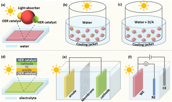
Particulate photocatalysts for the PC water splitting are usually composed of light absorbers and co-catalysts for the hydrogen evolution (HER) and/or the oxygen evolution reaction (OER), respectively. A practical model of PC water splitting demonstrated by Domen et al. is performed in panel reactors using photocatalyst sheets (Fig. 1a), which shares the same mechanism as that in the laboratory.5 Generally, the PC water splitting measurement in the laboratory is conducted in an air-tight reactor with a light window on the topside (Fig. 1b).25 To begin with, a certain amount of the particulate photocatalyst is dispersed in water and transferred into the reactor. After sealing the reactor and removing the air in the reactor via the vacuum pump/gas purge, a solar simulator is put over the top of the reactor as the light source. After lighting on, the HER and OER occur simultaneously on the surface of photocatalysts. Mechanical stirring is usually adopted to keep the suspension of photocatalyst particles. In addition, a thermostat-controlled system (cooling jacket) is necessary to minimise the light-induced temperature fluctuation of the reactor during photocatalytic reactions. The amount of generated H2 and O2 is analysed regularly using the gas chromatograph. However, most photocatalysts are not capable of triggering the overall water-splitting reaction due to thermodynamic/kinetic limitations.26 Half photocatalytic water splitting reactions, namely HER and OER, are usually conducted to evaluate the performance of photocatalysts with the assistance of sacrificial agents (electron donors for HER and electron acceptors for OER (Fig. 1c)).26 Those photocatalysts can form Z-scheme systems with proper redox couples (e.g., Fe2+/Fe3+) or solid charge intermediator (e.g., Au, graphene) to achieve overall water splitting.27,28 Different from the overall water splitting reaction, H2 or O2 is the only product recorded for the photocatalytic HER or OER, respectively. Here the temperature, pressure, pH value of reaction solutions and concentration of sacrificial agents have been demonstrated to influence the efficiency and stability of photocatalysts.292.2 Photoelectrochemical (PEC) water splitting
The predicted practical model of the PEC water splitting is based on an integrated system, in which the cathode and anode are deposited on two sides of a piece of a transparent conductor (TC) respectively to make an artificial leaf (Fig. 1d).7,30 Under solar irradiation, H2 and O2 are generated from the cathode side and the anode side, respectively. For general single photoanode/photocathode, the light absorber is deposited on a conductive substrate and then co-catalysts for target reactions are loaded on the surface of the light absorber. An ideal PEC water splitting process is that solar-powered HER and OER occur spontaneously on the photocathode and photoanode, respectively (Fig. 1e).17,30,31 However, it is challenging to match proper photoanodes and photocathodes for unbiased water splitting, thus external bias is applied in most of the case studies.32 Generally, a three-electrode system is usually used to investigate the performance of single photoelectrodes (Fig. 1f).33 Taking the photoanode as an example, the photoanode is defined as a working electrode (WE) to run the OER and the HER occurs on the cathode, namely the counter electrode (CE). A fixed area of the photoanode, where a large area (>1 cm2) is preferred for practical applications, is exposed to a solar simulator. Different from adding sacrificial agents in PC half-water splitting reactions, the extra bias is applied to provide sufficient potential for the water splitting reaction. Meanwhile, a reference electrode (RE) is applied to calibrate the applied bias. Like all the other electrochemical cells, conductive electrolytes are necessary for the photoelectrochemical cell. Here the temperature and the composition of electrolytes affect the PEC performance significantly.153. Stability evaluation
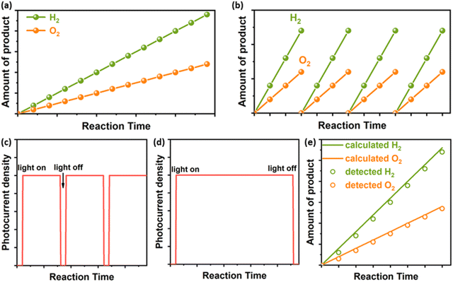
The definition of ‘catalyst’ is a substance that alters the rate of a chemical reaction but is itself unchanged at the end of the reaction, according to the Oxford Dictionary. This definition should also apply to photo(electro)catalysts, which are a branch of catalysts.34 A stable photocatalyst/photoelectrode should work normally under operational conditions without composite changes (crystal structure and chemical formula) during its lifetime. Therefore, the stability assessment should generally include the long-term operating measurement and the characterisation of structural properties of the applied materials after the durability test. A systematic process for the stability assessment of PC/PEC devices is proposed to advance the reliable report of the stability of photocatalysts and photoelectrodes (Fig. 2). For long-term testing, the stability of photocatalysts/photoelectrodes should be reported by three figures of metrics: run time, operational stability, and material stability. The properties of the catalyst material should be fully characterised, which mainly include morphology, crystal structure, composition, and photoelectronic properties. Additionally, the reaction solution should also be investigated to confirm the operational stability and material stability of photo(electro)catalytic devices. More details will be discussed below. | ||
| Fig. 2 Proposed stability assessment process of photocatalysts/photoelectrodes for solar fuel production. | ||
3.1 Long-term testing
![[thin space (1/6-em)]](https://www.rsc.org/images/entities/char_2009.gif) 900 h, 12 h d−1) is required for photocatalysts/photoelectrodes.12 A stability test of less than 24 h is usually too short to indicate what may happen to photocatalysts/photoelectrodes after one year, while it is impractical to conduct a five-year measurement. It seems that the photocatalysis community has not reached a consensus on how long the stability test should be performed.9 A period of at least 100 h is suggested for the early-stage stability assessment, which is time-efficient and feasible in most laboratories.
900 h, 12 h d−1) is required for photocatalysts/photoelectrodes.12 A stability test of less than 24 h is usually too short to indicate what may happen to photocatalysts/photoelectrodes after one year, while it is impractical to conduct a five-year measurement. It seems that the photocatalysis community has not reached a consensus on how long the stability test should be performed.9 A period of at least 100 h is suggested for the early-stage stability assessment, which is time-efficient and feasible in most laboratories.
3.2 Characterisation of photocatalysts/photoelectrodes and reaction solution after testing
Although the constant productivity directly demonstrates the stability of photo(electro)catalytic devices, it may not always reflect the actual stability of photocatalysts/photoelectrodes. If, for example, the self-decomposition of photocatalysts generates the same product as the target catalytic reaction, the initial instability of photocatalysts may be masked in this case.48 Therefore, the characterisation of catalyst materials and reaction solutions before and after durable testing is necessary to identify the stability of photocatalysts/photoelectrodes.33 Detailed structure–property relationships are usually investigated before the photocatalytic measurement to understand the mechanisms of unique/excellent performance, while the characterisation of photocatalysts/photoelectrodes after testing is generally oversimplified.45,49,50 The catalyst materials of a photocatalyst/photoelectrode mainly include a light absorber and co-catalysts for target reactions (HER/OER), which should be investigated after the stability test.34 A systematic characterisation of the structure and properties of photocatalysts/photoelectrodes should include but not be limited to morphology, crystal structure, composition, and photoelectronic properties. In addition, the reaction solution should also be investigated, which may indicate factors controlling the stability of photocatalysts/photoelectrodes.514. Identification of deactivation mechanisms
We define the deactivation of photo(electro)catalytic devices as a 50% decrease in productivity, which refers to classic catalytic systems.56 The deactivation of photocatalysts and photoelectrodes can be mainly divided into intrinsic instability of catalyst materials and photo/redox-induced instability. Most photo(electro)catalysts investigated show excellent intrinsic stability, thus the identification of deactivation mechanisms will focus on the photo/chemical-induced instability.13 The photo-generated electrons and holes in semiconducting light absorbers have been demonstrated to possess strong reducing and oxidising potentials, respectively.34 These electrons and holes may reduce or oxidise the catalyst itself rather than drive the HER or OER, namely photo-corrosion, causing the deactivation of photo(electro)catalytic reactions.4,8 The photo-corrosion is becoming one of the main challenges in PC and PEC water splitting with the continuous enhancement of efficiency.42,63,64 As stated by Landsmann et al., ‘A general strategy can be applied: identification and analysis of loss mechanisms in photoelectrodes and selection and deposition of specifically designed materials to address these problems.’65 Therefore, we would like to emphasise the purpose of long-term testing at the early stage of the photo(electro)catalytic technology, which is to find out possible unstable factors rather than demonstrate the stability of targeted materials. Comprehensive characterisations of deactivated photocatalysts and photoelectrodes and a deep understanding of deactivation mechanisms play a key role in guiding the photostability improvement of PC/PEC devices.4.1 Degradation of catalyst materials
The decrease of photocurrent and the H2/O2 evolution rate variation during long-term stability tests are generally derived from the physical and/or chemical changes of photocatalysts/photoelectrodes.15,51,63 The characterisation of deactivated photocatalysts/photoelectrodes gain a fundamental understanding of deactivation processes under operational conditions. A good model has been demonstrated based on the GaN:ZnO solid solution for PC water splitting.51After studying the effect of reaction conditions on photocatalytic performance, the Rh2−yCryO3/GaN:ZnO photocatalyst showed stable water-splitting activity for 3 days (72 h)under optimal reaction conditions.66 To further investigate the long-term durability of the Rh2−yCryO3/GaN:ZnO photocatalyst, the photocatalytic overall water splitting measurement was conducted within 0.5 years.51 The photocatalysts exhibited stable photocatalytic activity for over 3 months (2160 h) while losing 50% of the initial activity after 6 months (Fig. 4a). Through detailed characterisation of catalysts before and after the reaction, the catalyst deactivation was mainly attributed to the collapse of active sites (e.g., Rh2−yCryO3) for the HER and the oxidation of the nitride component by holes, together with the mechanical damage by stirring the reactant solution (Fig. 4b and c). Meanwhile, “accelerated deactivation” was performed using more intense light, of which the deactivation mechanism was consistent with that of the 6 month deactivation test. Furthermore, possible strategies have been proposed to improve the stability of the Rh2−yCryO3/GaN:ZnO photocatalyst, such as the reloading of Rh2−yCryO3 and the co-loading of co-catalysts for the OER to retard the self-oxidation process. Notably, it is suggested to investigate the degradation processes of the material fabricated by different methods, which can find out unstable factors induced by the material synthesis.67
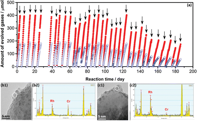 | ||
| Fig. 4 (a) Long-term measurement of Rh2−yCryO3/GaN:ZnO photocatalyst for overall water splitting under visible light. (b and c) Combination of TEM and EDS analysis for the Rh2−yCryO3/GaN photocatalyst (b) before and (c) after deactivation. Reproduced from ref. 51, copyright 2012, American Chemical Society. | ||
General PC/PEC water splitting processes convolve catalytic activities with light absorption and charge transfer, meanwhile, the photocatalyst/photoelectrode is a complex of the light absorber and the co-catalyst.9,34 The multi-step process and multi-component feature make it challenging to figure out deactivation mechanisms by characterisations of deactivated photocatalysts/photoelectrodes.68 Therefore, the delicate design of characterisation experiments with the assistance of sophisticated techniques provides a more accurate and thorough understanding of deactivation processes.20,67 Molybdenum disulfide (MoS2), with excellent catalytic activity for the HER, is regarded as one of the most promising candidates to replace Pt, while the stability of metal sulphides is a major concern for photocatalytic applications.69 Atomic force microscopy (AFM) is combined with micro-Raman spectroscopy to reveal the photo-induced degradation of MoS2 in fresh water. It is found that edge sites of MoS2 flakes are more vulnerable to photo-corrosion, compared to the basal plane (Fig. 5a and b). More interestingly, the edge sites of single-layer MoS2 are demonstrated to be more robust than that of the multi-layer MoS2 (Fig. 5c–e). As a result, single-layer MoS2 is preferred for PC/PEC water-splitting applications. Another example is the comparison of Ga-terminate and N-terminated GaN nanowires, which identifies the relationship between atomic configuration and the long-term stability of the p-GaN photoelectrode.70 Sophisticated characterisations clarify the essential role of nitrogen termination in preventing GaN nanowires from (photo)oxidation in air and aqueous electrolyte together with the efficient hole extraction in p-GaN.
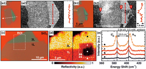 | ||
| Fig. 5 (a1 and b1) Optical microscopy (100×) and (a2 and b2) AFM images of exfoliated single- and trilayer flake of MoS2 on a Si/SiO2 substrate before (top) and after (bottom) laser line scan immersed in the electrolyte. (c) Optical microscopy image (100×) of exfoliated single-(1L) and trilayer (3L) MoS2 on a Si/SiO2 substrate. (d) Monochromatic reflectivity map of before (left) and after (right) a laser scan in the electrolyte of the region of interest (ROI) defined in (c). (e) Raman spectra of the spots marked in (d) of untreated, unaffected, and photodegraded regions. Reprinted with permission from ref. 61, copyright 2015, American Chemical Society. | ||
Recently, in situ or operando techniques have been emerging as powerful characterisation methods to complement the understanding of the degradation mechanisms of photocatalysts/photoelectrodes.67,71,72 Typically, in situ electrochemical atomic force microscopy (EC-AFM) is applied to gain more information on the photocorrosion of the BiVO4 photoanode. It confirms the film-dissolution-induced degradation and reveals nearly uniform etching on the surface exposed to the electrolyte (Fig. 6a).67 To further measure the dissolution rate of photoelectrodes in operando, the combination of the inductively coupled plasma mass spectrometry (ICP-MS) and an illuminated scanning flow cell (SFC) is designed, which enables time-resolved tracking of the dissolution rate of multiple elements in various kinds of electrolytes (Fig. 6b).73 Moreover, in situ spectroscopies have been demonstrated to identify chemical states of elements, local coordination geometries, and radicals of photocatalysts/photoelectrodes under operational conditions, including diffuse reflectance infrared Fourier-transform spectroscopy (DRIFTS), surface-enhance Raman spectroscopy (SERS), irradiated X-ray photoelectron spectroscopy (XPS), X-ray absorption spectroscopy (XAS), electron paramagnetic resonance (EPR) and so on.74–78 These operando techniques provide crucial information to recognise the early-state degradation of photocatalysts/photoelectrodes, such as the formation of electronic defects. In addition, computational methods have been developed to analyse the photocorrosion of photocatalysts/photoelectrodes in recent years.67 It is important to note that photocatalysts/photoelectrodes should be characterised under conditions related to the practical devices.
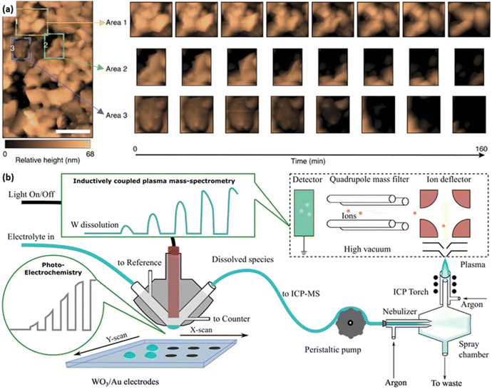 | ||
| Fig. 6 (a) In situ EC-AFM images of the BiVO4 photoanode. Three coloured boxes represent area 1 (yellow), area 2 (green) and area 3 (blue), of which operando scans are recorded in detail. Reprinted with permission from ref. 67, copyright 2016, Nature Publishing Group. (b) Schematic combination of the inductively coupled plasma mass spectrometry (ICP-MS) and the illuminated scan flow cell (SFC). Reprinted with permission from ref. 71, copyright 2018 Elsevier B.V. | ||
For photocatalysts and photoelectrodes, the stability of light absorbers and co-catalysts is usually investigated separately. However, the relationship between the light absorber and the co-catalyst determines that they will affect the stability of each other. The decomposition or dissolution of light absorbers has been demonstrated to loosen the interfacial structure between the light absorber and the co-catalyst or even detach the co-catalyst from the light absorber, resulting in the deactivation of the photo(electro)catalytic activities.48 On the other hand, the loading of proper co-catalysts on the surface of light absorbers promotes charge separation and accelerates the consumption of charge carriers for the water splitting reaction, which alleviates the charge-carrier-induced photocorrosion of light absorbers.57 Therefore, evaluating the stability of photocatalysts and photoelectrodes in their entirety is necessary to gain a full picture of the deactivation mechanism.
4.2 Impact of the operational environment
The degradation process is the interaction between active materials and environmental stimulations, which mainly include light intensity, O2, pressure, reaction solution and temperature for the solar-driven water-splitting reaction.4 In turn, proper control of the operational environment is possible to stabilise the photocatalysts/photoelectrodes.15 Thus, environmental stimulations should be analysed together with active materials when investigating the deactivation of photocatalysts and photoelectrodes. Generally, environmental stimulations do not work independently but are affected to a greater or lesser extent by each other (Fig. 7).20,29,67 The deep understanding of how environmental stimulations influence the stability of catalyst materials is essential to guide the design of durable PC/PEC devices.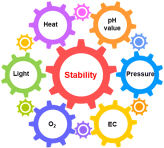 | ||
| Fig. 7 Schematic illustration of the relationship between the photo(electro)catalyst stability and various environmental factors. EC: electrolyte composition. | ||
5. Conclusion and outlook
The conclusions section should come in this section at the end of the article, before the acknowledgements. The stability challenge of the photo(electro)catalytic devices becomes a major obstacle towards practical solar fuel production. A reliable report of stability results is a prerequisite for the stability improvement of photocatalysts/photoelectrodes. To address the stability challenges effectively, we propose a systematic process for the stability evaluation of photo(electro)catalytic devices, which is expected to advance the reliable evaluation and report of stability results from different laboratories. Furthermore, the purpose of the early-stage stability evaluation is mainly to understand the deactivation mechanisms of photocatalysts/photoelectrodes, which will lay the foundation for the mitigation of unstable issues. Therefore, delicate development and design of experiments and ex/in situ techniques are necessary to enable a comprehensive understanding of the deactivation mechanisms of photocatalysts/photoelectrodes. Particular attention should be paid to the impact of the operational conditions on the stability of photo(electro)catalytic devices. This work is expected to initiate wide and intensive debates on stability assessment among the photo(electro)catalysis community, which will ensure continuous and meaningful improvement in this area of research. Further suggestions are proposed to address the stability challenges of photo(electro)catalysts.The long-term stability assessment is time/resource-consuming, and the long feedback loop impedes the development of stable photo(electro)catalytic devices towards solar fuel production. Therefore, the long-term stability assessment should be reserved for the most promising catalyst candidates, which have the best combination of stability and efficiency. Another possible strategy is to shorten the feedback loop by running the ‘accelerating test’, which has been demonstrated by some pioneering works.79 For instance, the replacement of visible light with intensive UV light speed up the deactivation of the Rh2−yCryO3/GaN:ZnO photocatalyst from a period of 4320 h to less than 100 h.51 Since the mechanisms of deactivation probably are not the same for different photocatalysts/photoelectrodes and are not yet thoroughly understood, it is not clear what acceleration factors are important. Continuous effort is required to clarify the deactivation mechanisms before reliable ‘accelerating tests’ can be performed.
Based on the understanding of deactivation mechanisms, the ongoing development of effective strategies is required to improve the stability of photocatalysts/photoelectrodes. As discussed in section 4, the photocorrosion of photocatalysts/photoelectrodes is mainly caused by the accumulation of photo-excited charge carriers. Therefore, the fast extraction of photo-generated electrons and holes from active materials should inhibit photocorrosion effectively. Facet engineering is a promising strategy to improve stability, due to the facet-dependent charge separation, catalytic activity, and stability.94,95 In addition, the electron transfer layer and hole transfer layer in perovskite solar cell devices may be a good reference for charge extraction.79 Moreover, the delicate design of co-catalysts should be pursued to accelerate water redox reactions and enhance the charge consumption rate.13 Meanwhile, photo-corrosion mostly involves the contact of active materials with water/electrolyte/O2. Thus, surface coating may be a proper strategy to isolate active materials from those unstable factors. With proper coating layers, metal halide perovskites can work as photoelectrodes for water splitting.96 Facial methods and advanced materials for surface coating are desirable to make durable and cost-effective photo(electro)catalytic devices.97 If a substantial fraction of the photo(electro)catalysis community continues to address the stability challenges of photo(electro)catalysts, it is believed that the advanced technology of photo(electro)catalytic solar to fuel conversion will emerge much faster.
Author contributions
L. Wang and M. Xiao designed and directed this perspective. M. Xiao wrote the manuscript. All the authors contributed to the discussion, editing and revision of this work.Conflicts of interest
There are conflicts to declare.Acknowledgements
The authors acknowledge the support from the Australian Research Council through its Laureate Fellowship project FL190100139 and Discovery Program DP200101900. K. M. would like to thank the financial support from JSPS KAKENHI (JP22H05148 and JPJSCCA20200004).References
- C. Bie, L. Wang and J. Yu, Chem, 2022, 8, 1567–1574 CAS.
- X.-S. Wang, L. Li, D. Li and J. Ye, Sol. RRL, 2020, 4, 1900547 CrossRef CAS.
- E. Gong, S. Ali, C. B. Hiragond, H. S. Kim, N. S. Powar, D. Kim, H. Kim and S.-I. In, Energy Environ. Sci., 2022, 15, 880–937 RSC.
- Z. Wang, Y. Gu, L. Zheng, J. Hou, H. Zheng, S. Sun and L. Wang, Adv. Mater., 2022, 34, 2106776 CrossRef CAS PubMed.
- H. Nishiyama, T. Yamada, M. Nakabayashi, Y. Maehara, M. Yamaguchi, Y. Kuromiya, Y. Nagatsuma, H. Tokudome, S. Akiyama, T. Watanabe, R. Narushima, S. Okunaka, N. Shibata, T. Takata, T. Hisatomi and K. Domen, Nature, 2021, 598, 304–307 CrossRef CAS PubMed.
- H. Song, S. Luo, H. Huang, B. Deng and J. Ye, ACS Energy Lett., 2022, 7, 1043–1065 CrossRef CAS.
- B. A. Pinaud, J. D. Benck, L. C. Seitz, A. J. Forman, Z. Chen, T. G. Deutsch, B. D. James, K. N. Baum, G. N. Baum, S. Ardo, H. Wang, E. Miller and T. F. Jaramillo, Energy Environ. Sci., 2013, 6, 1983–2002 RSC.
- J. Su, Y. Wei and L. Vayssieres, J. Phys. Chem. Lett., 2017, 8, 5228–5238 CrossRef CAS PubMed.
- J. H. Kim, D. Hansora, P. Sharma, J.-W. Jang and J. S. Lee, Chem. Soc. Rev., 2019, 48, 1908–1971 RSC.
- G. Liu, S. Ye, P. Yan, F. Xiong, P. Fu, Z. Wang, Z. Chen, J. Shi and C. Li, Energy Environ. Sci., 2016, 9, 1327–1334 RSC.
- J. Fu, Z. Fan, M. Nakabayashi, H. Ju, N. Pastukhova, Y. Xiao, C. Feng, N. Shibata, K. Domen and Y. Li, Nat. Commun., 2022, 13, 729 CrossRef CAS PubMed.
- J. Schneidewind, Adv. Energy Mater., 2022, 12, 2200342 CrossRef CAS.
- X. Tao, Y. Zhao, S. Wang, C. Li and R. Li, Chem. Soc. Rev., 2022, 51, 3561–3608 RSC.
- D. K. Lee, D. Lee, M. A. Lumley and K.-S. Choi, Chem. Soc. Rev., 2019, 48, 2126–2157 RSC.
- D. K. Lee and K.-S. Choi, Nat. Energy, 2018, 3, 53–60 CrossRef CAS.
- J.-B. Pan, B.-H. Wang, J.-B. Wang, H.-Z. Ding, W. Zhou, X. Liu, J.-R. Zhang, S. Shen, J.-K. Guo, L. Chen, C.-T. Au, L.-L. Jiang and S.-F. Yin, Angew. Chem., Int. Ed., 2021, 60, 1433–1440 CrossRef CAS PubMed.
- L. Pan, J. H. Kim, M. T. Mayer, M.-K. Son, A. Ummadisingu, J. S. Lee, A. Hagfeldt, J. Luo and M. Grätzel, Nat. Catal., 2018, 1, 412–420 CrossRef CAS.
- H. Huang, B. Pradhan, J. Hofkens, M. B. J. Roeffaers and J. A. Steele, ACS Energy Lett., 2020, 5, 1107–1123 CrossRef CAS.
- N. Pastukhova, A. Mavrič and Y. Li, Adv. Mater. Interfaces, 2021, 8, 2002100 CrossRef CAS.
- G. F. Samu and C. Janáky, J. Am. Chem. Soc., 2020, 142, 21595–21614 CrossRef CAS PubMed.
- J.-B. Pan, S. Shen, L. Chen, C.-T. Au and S.-F. Yin, Adv. Funct. Mater., 2021, 31, 2104269 CrossRef CAS.
- E. Zhao, K. Du, P.-F. Yin, J. Ran, J. Mao, T. Ling and S.-Z. Qiao, Adv. Sci., 2022, 9, 2104363 CrossRef CAS PubMed.
- S. Chen, T. Takata and K. Domen, Nat. Rev. Mater., 2017, 2, 17050 CrossRef CAS.
- T. Hisatomi, J. Kubota and K. Domen, Chem. Soc. Rev., 2014, 43, 7520–7535 RSC.
- T. Takata, C. Pan and K. Domen, Sci. Technol. Adv. Mater., 2015, 16, 033506 CrossRef PubMed.
- M. Xiao, Z. Wang, M. Lyu, B. Luo, S. Wang, G. Liu, H.-M. Cheng and L. Wang, Adv. Mater., 2019, 31, 1801369 CrossRef PubMed.
- P. Zhou, J. Yu and M. Jaroniec, Adv. Mater., 2014, 26, 4920–4935 CrossRef CAS PubMed.
- J. Low, C. Jiang, B. Cheng, S. Wageh, A. A. Al-Ghamdi and J. Yu, Small Methods, 2017, 1, 1700080 CrossRef.
- Q. Wang, T. Hisatomi, Q. Jia, H. Tokudome, M. Zhong, C. Wang, Z. Pan, T. Takata, M. Nakabayashi, N. Shibata, Y. Li, I. D. Sharp, A. Kudo, T. Yamada and K. Domen, Nat. Mater., 2016, 15, 611–615 CrossRef CAS PubMed.
- D. G. Nocera, Acc. Chem. Res., 2012, 45, 767–776 CrossRef CAS PubMed.
- Z. Luo, T. Wang and J. Gong, Chem. Soc. Rev., 2019, 48, 2158–2181 RSC.
- W. Yang, R. R. Prabhakar, J. Tan, S. D. Tilley and J. Moon, Chem. Soc. Rev., 2019, 48, 4979–5015 RSC.
- Z. Chen, T. G. Deutsch, H. N. Dinh, K. Domen, K. Emery, A. J. Forman, N. Gaillard, R. Garland, C. Heske, T. F. Jaramillo, A. Kleiman-Shwarsctein, E. Miller, K. Takanabe and J. Turner, in Photoelectrochemical Water Splitting: Standards, Experimental Methods, and Protocols, ed. Z. Chen, H. N. Dinh and E. Miller, Springer New York, New York, NY, 2013, pp. 17–44, DOI:10.1007/978-1-4614-8298-7_3.
- A. Kudo and Y. Miseki, Chem. Soc. Rev., 2009, 38, 253–278 RSC.
- Z. Wang, T. Hisatomi, R. Li, K. Sayama, G. Liu, K. Domen, C. Li and L. Wang, Joule, 2021, 5, 344–359 CrossRef CAS.
- X. Zhao, S. Chen, H. Yin, S. Jiang, K. Zhao, J. Kang, P. F. Liu, L. Jiang, Z. Zhu, D. Cui, P. Liu, X. Han, H. G. Yang and H. Zhao, Matter, 2020, 3, 935–949 CrossRef.
- S. Park, W. J. Chang, C. W. Lee, S. Park, H.-Y. Ahn and K. T. Nam, Nat. Energy, 2016, 2, 16185 CrossRef.
- L. Lin, Z. Lin, J. Zhang, X. Cai, W. Lin, Z. Yu and X. Wang, Nat. Catal., 2020, 3, 649–655 CrossRef CAS.
- M. Liu, Y. Chen, J. Su, J. Shi, X. Wang and L. Guo, Nat. Energy, 2016, 1, 16151 CrossRef CAS.
- T. Takata, J. Jiang, Y. Sakata, M. Nakabayashi, N. Shibata, V. Nandal, K. Seki, T. Hisatomi and K. Domen, Nature, 2020, 581, 411–414 CrossRef CAS PubMed.
- Y. Zhang, Z. Sun, Z. Wang, Y. Zang and X. Tao, Int. J. Hydrogen Energy, 2022, 47, 8829–8840 CrossRef CAS.
- D. Zhao, Y. Wang, C.-L. Dong, Y.-C. Huang, J. Chen, F. Xue, S. Shen and L. Guo, Nat. Energy, 2021, 6, 388–397 CrossRef CAS.
- Y. Xiao, C. Feng, J. Fu, F. Wang, C. Li, V. F. Kunzelmann, C.-M. Jiang, M. Nakabayashi, N. Shibata, I. D. Sharp, K. Domen and Y. Li, Nat. Catal., 2020, 3, 932–940 CrossRef CAS.
- S. Wang, P. Chen, Y. Bai, J.-H. Yun, G. Liu and L. Wang, Adv. Mater., 2018, 30, 1800486 CrossRef PubMed.
- S. Wang, T. He, P. Chen, A. Du, K. Ostrikov, W. Huang and L. Wang, Adv. Mater., 2020, 32, 2001385 CrossRef CAS PubMed.
- Q. Mi, A. Zhanaidarova, B. S. Brunschwig, H. B. Gray and N. S. Lewis, Energy Environ. Sci., 2012, 5, 5694–5700 RSC.
- W. Kim, T. Tachikawa, D. Monllor-Satoca, H.-i. Kim, T. Majima and W. Choi, Energy Environ. Sci., 2013, 6, 3732–3739 RSC.
- P. Chen, X. a. Dong, M. Huang, K. Li, L. Xiao, J. Sheng, S. Chen, Y. Zhou and F. Dong, ACS Catal., 2022, 12, 4560–4570 CrossRef CAS.
- M. Liu, C. Wei, H. Zhuzhang, J. Zhou, Z. Pan, W. Lin, Z. Yu, G. Zhang and X. Wang, Angew. Chem., Int. Ed., 2022, 61, e202113389 CAS.
- P. Zhou, H. Chen, Y. Chao, Q. Zhang, W. Zhang, F. Lv, L. Gu, Q. Zhao, N. Wang, J. Wang and S. Guo, Nat. Commun., 2021, 12, 4412 CrossRef CAS PubMed.
- T. Ohno, L. Bai, T. Hisatomi, K. Maeda and K. Domen, J. Am. Chem. Soc., 2012, 134, 8254–8259 CrossRef CAS PubMed.
- W. Yuan, B. Zhu, X.-Y. Li, T. W. Hansen, Y. Ou, K. Fang, H. Yang, Z. Zhang, J. B. Wagner, Y. Gao and Y. Wang, Science, 2020, 367, 428–430 CrossRef CAS PubMed.
- I. Tsuji, H. Kato, H. Kobayashi and A. Kudo, J. Am. Chem. Soc., 2004, 126, 13406–13413 CrossRef CAS PubMed.
- G. Zhang, L. Lin, G. Li, Y. Zhang, A. Savateev, S. Zafeiratos, X. Wang and M. Antonietti, Angew. Chem., Int. Ed., 2018, 57, 9372–9376 CrossRef CAS PubMed.
- S. Cao, Y. Chen, H. Wang, J. Chen, X. Shi, H. Li, P. Cheng, X. Liu, M. Liu and L. Piao, Joule, 2018, 2, 549–557 CrossRef CAS.
- C. Spöri, J. T. H. Kwan, A. Bonakdarpour, D. P. Wilkinson and P. Strasser, Angew. Chem., Int. Ed., 2017, 56, 5994–6021 CrossRef PubMed.
- X. Li, J. Yu, M. Jaroniec and X. Chen, Chem. Rev., 2019, 119, 3962–4179 CrossRef CAS PubMed.
- H. Chai, P. Wang, T. Wang, L. Gao, F. Li and J. Jin, ACS Appl. Mater. Interfaces, 2021, 13, 47572–47580 CrossRef CAS PubMed.
- M. Matsukawa, R. Ishikawa, T. Hisatomi, Y. Moriya, N. Shibata, J. Kubota, Y. Ikuhara and K. Domen, Nano Lett., 2014, 14, 1038–1041 CrossRef CAS PubMed.
- Q. Guo, C. Zhou, Z. Ma, Z. Ren, H. Fan and X. Yang, Chem. Soc. Rev., 2016, 45, 3701–3730 RSC.
- E. Parzinger, B. Miller, B. Blaschke, J. A. Garrido, J. W. Ager, A. Holleitner and U. Wurstbauer, ACS Nano, 2015, 9, 11302–11309 CrossRef CAS PubMed.
- T. Lange, S. Reichenberger, M. Rohe, M. Bartsch, L. Kampermann, J. Klein, J. Strunk, G. Bacher, R. Schlögl and S. Barcikowski, Adv. Funct. Mater., 2021, 31, 2009323 CrossRef CAS.
- Q. Wang, M. Nakabayashi, T. Hisatomi, S. Sun, S. Akiyama, Z. Wang, Z. Pan, X. Xiao, T. Watanabe, T. Yamada, N. Shibata, T. Takata and K. Domen, Nat. Mater., 2019, 18, 827–832 CrossRef CAS PubMed.
- Z. Wang, Y. Inoue, T. Hisatomi, R. Ishikawa, Q. Wang, T. Takata, S. Chen, N. Shibata, Y. Ikuhara and K. Domen, Nat. Catal., 2018, 1, 756–763 CrossRef CAS.
- S. Landsmann, Y. Surace, M. Trottmann, S. Dilger, A. Weidenkaff and S. Pokrant, ACS Appl. Mater. Interfaces, 2016, 8, 12149–12157 CrossRef CAS PubMed.
- K. Maeda, K. Teramura, H. Masuda, T. Takata, N. Saito, Y. Inoue and K. Domen, J. Phys. Chem. B, 2006, 110, 13107–13112 CrossRef CAS PubMed.
- F. M. Toma, J. K. Cooper, V. Kunzelmann, M. T. McDowell, J. Yu, D. M. Larson, N. J. Borys, C. Abelyan, J. W. Beeman, K. M. Yu, J. Yang, L. Chen, M. R. Shaner, J. Spurgeon, F. A. Houle, K. A. Persson and I. D. Sharp, Nat. Commun., 2016, 7, 12012 CrossRef PubMed.
- S. Cao and L. Piao, Angew. Chem., Int. Ed., 2020, 59, 18312–18320 CrossRef CAS PubMed.
- C. Wu, J. Zhang, X. Tong, P. Yu, J.-Y. Xu, J. Wu, Z. M. Wang, J. Lou and Y.-L. Chueh, Small, 2019, 15, 1900578 CrossRef PubMed.
- M. G. Kibria, R. Qiao, W. Yang, I. Boukahil, X. Kong, F. A. Chowdhury, M. L. Trudeau, W. Ji, H. Guo, F. J. Himpsel, L. Vayssieres and Z. Mi, Adv. Mater., 2016, 28, 8388–8397 CrossRef CAS PubMed.
- J. Knöppel, S. Zhang, F. D. Speck, K. J. J. Mayrhofer, C. Scheu and S. Cherevko, Electrochem. Commun., 2018, 96, 53–56 CrossRef.
- S. Zhang, I. Ahmet, S.-H. Kim, O. Kasian, A. M. Mingers, P. Schnell, M. Kölbach, J. Lim, A. Fischer, K. J. J. Mayrhofer, S. Cherevko, B. Gault, R. van de Krol and C. Scheu, ACS Appl. Energy Mater., 2020, 3, 9523–9527 CrossRef CAS PubMed.
- S. Zhang, M. Rohloff, O. Kasian, A. M. Mingers, K. J. J. Mayrhofer, A. Fischer, C. Scheu and S. Cherevko, J. Phys. Chem. C, 2019, 123, 23410–23418 CrossRef CAS.
- L. Yuan, S.-F. Hung, Z.-R. Tang, H. M. Chen, Y. Xiong and Y.-J. Xu, ACS Catal., 2019, 9, 4824–4833 CrossRef CAS.
- Y. Hu, F. Zhan, Q. Wang, Y. Sun, C. Yu, X. Zhao, H. Wang, R. Long, G. Zhang, C. Gao, W. Zhang, J. Jiang, Y. Tao and Y. Xiong, J. Am. Chem. Soc., 2020, 142, 5618–5626 CrossRef CAS PubMed.
- L. Wang, B. Cheng, L. Zhang and J. Yu, Small, 2021, 17, 2103447 CrossRef CAS PubMed.
- F. Liu, N. Feng, Q. Wang, J. Xu, G. Qi, C. Wang and F. Deng, J. Am. Chem. Soc., 2017, 139, 10020–10028 CrossRef CAS PubMed.
- S. A. Bonke, T. Risse, A. Schnegg and A. Brückner, Nat. Rev. Methods Primers, 2021, 1, 33 CrossRef CAS.
- C. C. Boyd, R. Cheacharoen, T. Leijtens and M. D. McGehee, Chem. Rev., 2019, 119, 3418–3451 CrossRef CAS PubMed.
- J. Xiao, Q. Han, Y. Xie, J. Yang, Q. Su, Y. Chen and H. Cao, Environ. Sci. Technol., 2017, 51, 13380–13387 CrossRef CAS PubMed.
- Y. Nosaka and A. Y. Nosaka, Chem. Rev., 2017, 117, 11302–11336 CrossRef CAS PubMed.
- N. I. Kolev, in Multiphase Flow Dynamics 4: Turbulence, Gas Adsorption and Release, Diesel Fuel Properties, ed. N. I. Kolev, Springer Berlin Heidelberg, Berlin, Heidelberg, 2012, pp. 209–239, DOI:10.1007/978-3-642-20749-5_11.
- X. Ning and G. Lu, Nanoscale, 2020, 12, 1213–1223 RSC.
- M. Sarnowska, K. Bienkowski, P. J. Barczuk, R. Solarska and J. Augustynski, Adv. Energy Mater., 2016, 6, 1600526 CrossRef.
- Y.-D. Wang, T.-W. Lee, Y.-C. Lo, W.-J. Hong and C. Chen, Carbon, 2021, 175, 223–232 CrossRef CAS.
- Y. Yang, Y. Ling, G. Wang, T. Liu, F. Wang, T. Zhai, Y. Tong and Y. Li, Nano Lett., 2015, 15, 7051–7057 CrossRef CAS PubMed.
- C.-F. Liu, Y.-J. Lu and C.-C. Hu, ACS Omega, 2018, 3, 3429–3439 CrossRef CAS PubMed.
- G. Zhang, G. Li, T. Heil, S. Zafeiratos, F. Lai, A. Savateev, M. Antonietti and X. Wang, Angew. Chem., Int. Ed., 2019, 58, 3433–3437 CrossRef CAS PubMed.
- E. M. Hutter and T. J. Savenije, ACS Energy Lett., 2018, 3, 2068–2069 CrossRef CAS PubMed.
- L. Huldt, N. G. Nilsson and K. G. Svantesson, Appl. Phys. Lett., 1979, 35, 776–777 CrossRef CAS.
- R. Scott, S. Kickhöfel, O. Schoeps, A. Antanovich, A. Prudnikau, A. Chuvilin, U. Woggon, M. Artemyev and A. W. Achtstein, Phys. Chem. Chem. Phys., 2016, 18, 3197–3203 RSC.
- M. Matsumura, S. Furukawa, Y. Saho and H. Tsubomura, J. Phys. Chem., 1985, 89, 1327–1329 CrossRef CAS.
- M. J. Berr, P. Wagner, S. Fischbach, A. Vaneski, J. Schneider, A. S. Susha, A. L. Rogach, F. Jäckel and J. Feldmann, Appl. Phys. Lett., 2012, 100, 223903 CrossRef.
- H. L. Tan, X. Wen, R. Amal and Y. H. Ng, J. Phys. Chem. Lett., 2016, 7, 1400–1405 CrossRef CAS PubMed.
- S. Wang, G. Liu and L. Wang, Chem. Rev., 2019, 119, 5192–5247 CrossRef CAS PubMed.
- I. Poli, U. Hintermair, M. Regue, S. Kumar, E. V. Sackville, J. Baker, T. M. Watson, S. Eslava and P. J. Cameron, Nat. Commun., 2019, 10, 2097 CrossRef PubMed.
- J. Tan, B. Kang, K. Kim, D. Kang, H. Lee, S. Ma, G. Jang, H. Lee and J. Moon, Nat. Energy, 2022, 7, 537–547 CrossRef CAS.
| This journal is © The Royal Society of Chemistry 2023 |

