 Open Access Article
Creative Commons Attribution 3.0 Unported Licence
Through-space hopping transport in an iodine-doped perylene-based metal–organic framework†
Gonçalo
Valente‡
 a,
María
Esteve-Rochina‡
 b,
Ana
Paracana
c,
Antonio
Rodríguez-Diéguez
 d,
Duane
Choquesillo-Lazarte
 e,
Enrique
Ortí
 b,
Joaquín
Calbo
 *b,
Marina
Ilkaeva
 a,
Luís
Mafra
 a,
Miguel A.
Hernández-Rodríguez
 c,
João
Rocha
 a,
Helena
Alves
 b and
Manuel
Souto
 *a
*a
aDepartment of Chemistry, CICECO-Aveiro Institute of Materials, University of Aveiro, Aveiro, 3810-393, Portugal. E-mail: manuel.souto@ua.pt
bInstituto de Ciencia Molecular (ICMol), Universidad de Valencia, c/Catedrático José Beltrán, 2, 46980 Paterna, Spain. E-mail: joaquin.calbo@uv.es
cDepartment of Physics, CICECO-Aveiro Institute of Materials, University of Aveiro, Aveiro, 3810-393, Portugal
dDepartment of Inorganic Chemistry, University Granada, 18071, Granada, Spain
eLaboratorio de Estudios Cristalográficos, IACT, CSIC-Universidad Granada, Granada, 18100, Spain
First published on 4th July 2022
Abstract
Electrically conductive metal–organic frameworks (MOFs) have emerged in the past few years as promising materials towards applications in (opto)electronics, electrocatalysis and energy storage, among others. One of the most common strategies for the design of conductive MOFs is based on the use of electroactive organic ligands and their partial oxidation/reduction to increase the number of charge carriers. Although perylene salts were reported as the first molecular conductors, they have been scarcely explored as building blocks for the construction of conductive MOFs. Herein we report the electrical conductivity enhancement of a microporous perylene-based MOF upon partial ligand oxidation by using two-probe single-crystal devices. The origin of the conductivity enhancement is rationalised by means of spectroscopic studies and quantum-chemical calculations, supporting a through-space hopping transport along the herringbone perylene packing. This study opens the way for the design of conductive MOFs based on perylene building blocks.
Design, System, ApplicationThe design of electrically conductive metal–organic frameworks (MOFs) is a field of growing interest as the synthesis of molecular-based frameworks combining porosity and high conductivity are of interest towards applications in (opto)electronics, energy storage and electrocatalysis, among others. Although most reported MOFs are insulators, some design strategies have been proposed to increase their electronic conductivity. In this sense, the use of electroactive organic ligands exhibiting short noncovalent interactions has been proved to be a promising strategy to promote efficient charge transport pathways. Here we report a detailed study of how the herringbone arrangement of perylene ligands incorporated in a microporous MOF results in a through-space hopping transport. In addition, we demonstrate how the conductivity can be enhanced by partial oxidation of the perylene ligands. In summary, we demonstrate how the conductivity in a perylene-based MOF can be modulated depending on the arrangement of the electroactive ligands and by iodine doping. |
Introduction
Metal–organic frameworks (MOFs) are crystalline porous materials constructed from multitopic organic ligands and metallic nodes, which have received considerable attention towards a wide range of potential applications due to their considerable chemical and structural versatility.1,2 Besides their use in conventional applications, such as gas storage/separation and catalysis, electrically conductive MOFs have gained a great deal of interest especially in the fields of (opto)electronics, electrocatalysis and energy storage.3–5 In this direction, achieving efficient charge transport in MOFs is required towards their implementation in advanced multifunction electronic devices. Although most reported MOFs are insulators, certain synthetic strategies have been devised to increase their electrical conductivity.5 One such strategy, known as “through-space approach”, is based on noncovalent interactions between the organic moieties to promote efficient charge-transport pathways.5,6 In particular, different conjugated electroactive building blocks have been incorporated in MOFs giving rise to semiconducting properties (σ = 10−3–10−9 S cm−1) thanks to the short intermolecular interactions between the linkers.3,7,8 For example, conductive MOFs based on through-space conduction pathways are built from organic building blocks, such as tetrathiafulvalenes,9–11 anthracenes,12 pyrenes,13 naphthalenes,14 naphthalene diimides,15,16 diazaphenalene radicals17 and pentacenes.18 Otherwise, encapsulation of doping molecules, such as iodine,19–22 within the pores is another efficient strategy to enhance the conductivity of MOFs by several orders of magnitude due to the spontaneous formation of free charge carriers.The discovery of relatively high electrical conductivity in a perylene–bromine complex23 (considered the first organic conductor) in the 1950s initiated the vast field of molecular conductors.24,25 Since then, many perylene derivatives were extensively employed in the synthesis of molecular conductors, in combination with various inorganic anions (Br−, I−…) and organic acceptors, such as TCNQ.26,27 The conductivity of perylene salts originates from the π–π intermolecular interactions between these planar molecules, which should be optimally stacked in a close and parallel manner. The structural arrangement allied to the partial oxidation of perylenes may result in incompletely filled bands and metallic conductivities.26
Despite their promising electrical properties, perylenes have been scarcely explored as building blocks for the construction of electrically conductive MOFs.3 Most perylene-based MOFs have been studied towards gas sorption and sensing applications due to the remarkable luminescence properties of perylene.28–35 On the other hand, the study of the electrical conductivity of alkali metal-based MOFs is limited to a very recently reported family of tetrathiafulvalene–tetracarboxylate MOFs.36 In this direction, the perylene-3,4,9,10-tetracarboxylate (PTC) ligand has been combined with potassium ions leading to two-37 and three-dimensional coordination polymers exhibiting permanent microporosity, humidity-dependent impedance and proton conductivity.31,32 However, the structure-dependent electrical conductivity and charge-transport mechanism of doped perylene-based MOFs have not been investigated in detail.
Inspired by the design of perylene-based molecular conductors, herein we report the electrical conductivity enhancement up to three orders of magnitude of a perylene-based MOF (Per-MOF)32 upon partial ligand oxidation by iodine doping using two-probe single-crystal devices. Solid-state cyclic voltammetry confirmed the possibility of oxidation of the electroactive ligands, whereas spectroscopic studies demonstrated the presence of perylene radical cation and polyiodine anion species. Quantum-chemical calculations were performed to further understand the origin of the conductivity enhancement, which is explained in terms of a through-space hopping charge-transport mechanism. This study highlights the great potential of doped perylenes as building blocks for the construction of electrically conductive MOFs.
Results and discussion
Synthesis and crystal structure
Per-MOF single-crystals were obtained by optimizing a previously reported method,32 consisting in mixing the ligand 3,4,9,10-perylenetetracarboxylic acid (H4PTCA) and KOH in water and heating the reaction mixture with infrared light for 24 h (see ESI†). Crystals were exhaustively washed with DMF and EtOH to remove any unreacted ligand, as confirmed by IR spectroscopy (Fig. S1†). Finally, the material was filtered off and dried at 100 °C.
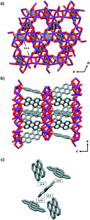
Per-MOF crystallises in the trigonal P![[3 with combining macron]](https://www.rsc.org/images/entities/char_0033_0304.gif) space group. The 6- or 8-coordinated K+ ions are connected through bridging carboxylate groups from the tetratopic perylene ligands (Fig. 1).32 The crystal structure reveals 1D hexagonal microporous channels of ca. 8.6 Å along the c-axis (Fig. 1a), resulting in a calculated solvent-accessible volume of ca. 20% of the total (see Table S1, ESI†). The perylene moieties stack to form one-dimensional chains along the a-axis (Fig. 1b and S2†). Perylene moieties are arranged in a herringbone stacking showing the shortest C⋯C intermolecular distances of 3.6 Å between adjacent ligands (Fig. 1c). Note that such herringbone arrangement is a common molecular packing of many organic semiconductors.38,39
space group. The 6- or 8-coordinated K+ ions are connected through bridging carboxylate groups from the tetratopic perylene ligands (Fig. 1).32 The crystal structure reveals 1D hexagonal microporous channels of ca. 8.6 Å along the c-axis (Fig. 1a), resulting in a calculated solvent-accessible volume of ca. 20% of the total (see Table S1, ESI†). The perylene moieties stack to form one-dimensional chains along the a-axis (Fig. 1b and S2†). Perylene moieties are arranged in a herringbone stacking showing the shortest C⋯C intermolecular distances of 3.6 Å between adjacent ligands (Fig. 1c). Note that such herringbone arrangement is a common molecular packing of many organic semiconductors.38,39
Thermogravimetric analysis and gas sorption properties
Thermogravimetric analysis (TGA) of Per-MOF (Fig. S3, ESI†) shows a mass loss (∼5%) between 25 and 100 °C attributed to the removal of EtOH solvent molecules, followed by a wide plateau until the decomposition of the material at 450 °C, demonstrating its high thermal stability. Gas sorption (CO2, N2) measurements were performed on activated Per-MOF (120 °C for 12 h under vacuum), to evaluate its porosity (Fig. S4, ESI†). The CO2 adsorption isotherm (273 K) reveals an uptake of 20 cm3 g−1 at 1 bar, indicating the presence of intrinsic micropores in the MOF. The pore size distribution was calculated by Grand Canonical Monte Carlo (GCMC) approach using a carbon slit-shaped pore model (Fig. S4b†) revealing a pore size range between 4 and 8 Å. The 77 K N2 adsorption isotherm shows a minimum uptake of N2, in line with other similar MOFs reported.31,36 This type of selective CO2 adsorption has been attributed to the high quadrupole moment of the CO2 molecules that strongly interact with the large π-electron cloud of the aromatic rings of π-conjugated ligands,10,31,40 in this case perylene.Electrochemical properties
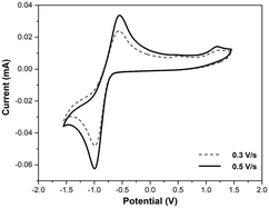
The electrochemical properties of Per-MOF and its organic building block were investigated by cyclic voltammetry (CV). The CV of the H4PTCA ligand in DMF (Fig. S5, ESI†) shows a quasi-reversible redox process at −0.85 V (vs. Ag/AgCl) assigned to the reduction of the acid groups,41 and a more irreversible redox process at +1.10 V attributed to the oxidation of the perylene, in agreement with other similar compounds.42 The solid-state CV of Per-MOF in CH3CN shows the oxidation process occurring at similar potentials, +1.17 V (Fig. 2 and S6, ESI†), as expected for perylene derivatives,26,34 confirming the possibility of oxidation of the electroactive ligands. A quasi-reversible reduction process is observed at −0.76 V. The relatively large peak-to-peak separation can be explained by the partial dissolution of the ligand after several cycles (note that at negative potentials the reduction of the carboxylate groups takes place) or by the poor diffusion of the electrolyte through the micropores of the MOF. As expected, the perylene-based MOF oxidation process (∼1.2 V) occurs at lower potentials than for pyrene-based MOFs (∼1.4 V).43 The ionization potential (IP) was estimated from the oxidation potential to be 5.6 eV, in full agreement with theoretical calculations (see section 6 in the ESI† and Table S2).Iodine doping
In view of the promising electrochemical properties and potential partial oxidation of the perylene moieties, chemical doping by iodine encapsulation was performed to obtain I2@Per-MOF using a diffusion technique and adapting a reported procedure.19–22 The activated crystals (heated at 200 °C for 2 h) of Per-MOF were immersed in a saturated solution of iodine in cyclohexane (0.1 M) at room temperature for 24 h (Fig. S7, ESI†). Then, the crystals were washed with cyclohexane to remove the physisorbed iodine. The crystallinity and morphology of Per-MOF crystals after doping were preserved, as confirmed by powder X-ray diffraction (PXRD) (Fig. S8, ESI†) and scanning electron microscopy (SEM) (Fig. S9, ESI†), respectively. The pure crystalline phase of Per-MOF was confirmed by PXRD with some differences in relative intensity between simulated and experimental patterns that might be due to the preferred crystalline orientation. The PXRD reflections of I2@Per-MOF did not change their positions relatively to Per-MOF, and only slight changes were observed in the relative intensities, as previously reported for other iodine-doped MOFs (Fig. S8†).19 Moreover, energy-dispersive X-ray spectroscopy (EDS) confirmed the homogeneous distribution of iodine through the I2@Per-MOF crystals (Fig. S10 and S11, ESI†). IR (Fig. S12, ESI†) and Raman (Fig. S13a, ESI†) spectra of Per-MOF and I2@Per-MOF did not show any significant differences in the 400–2000 cm−1 region. The most important changes are observed in the low-frequency spectral region (100–200 cm−1) of the Raman spectrum of I2@Per-MOF, in which four new bands at 178, 171, 153 and 139 cm−1 are observed (Fig. S13b, ESI†). Bands close to 180 cm−1 are attributed to symmetric stretching vibrations of I2 whereas bands at 130–142 and 150 cm−1 are related to I3− stretching vibrations.44–46 Thus, these results indicate that both molecular iodine (I2) and polyiodine anions such as I3− are present within the framework. Importantly, the electron paramagnetic resonance (EPR) spectrum of I2@Per-MOF crystals at room temperature showed an intense signal at g = 2.003 ascribed to perylene radical cation species (Fig. S14, ESI†),47 confirming the partial oxidation of perylene ligands with iodine. The iodine content was estimated by ICP-MS, yielding a ratio of 1 I2 molecule per 3 perylene molecules. A similar value was calculated by TGA (Fig. S15, ESI†), although in this case the amount of iodine may be overestimated due to the possible presence of adsorbed solvents. The relatively low content of MOF-encapsulated iodine may be due to problems of diffusion through the microporous channels.Optical properties
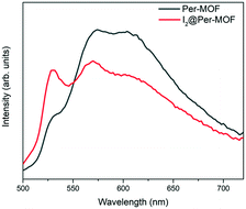
The photophysical properties of Per-MOF and I2@Per-MOF were characterized in the solid state (Fig. 3). For comparison, the absorption, emission (λexc = 366 nm) and excitation (λdet = 571 nm) spectra of the H4PTCA ligand were also measured in solution (Fig. S16, ESI†). Upon the addition of an increasing amount of I2 equivalents to the ligand, the UV-vis spectrum of H4PTCA displays a growing intense absorption band at 360 nm (Fig. S17, ESI†) assigned to I3− species,48 suggesting the reduction of iodine upon oxidation of the perylene ligands. The emission spectra of the ligand H4PTCA in solution upon addition of increasing amounts of I2 were also measured as reference (Fig. S18, ESI†). The intensity of the band at 540 nm increases, which could also be related to the formation of I3− species (emission at 532 nm, Fig. S18, ESI†).The solid-state emission spectra of Per-MOF and I2@Per-MOF (λexc = 368 nm) display three main bands at 528, 559 and 605 nm (Fig. 3 and S19†), in agreement with other similar systems.31,37 The relative intensity of the 528 nm band increases in the case of I2@Per-MOF (Fig. 3), a signature that could be related to the presence of chemisorbed I3− in the pore channels. Absolute quantum yields of Per-MOF and I2@Per-MOF were determined using integrating sphere method obtaining values of 0.5% and 0.3%, respectively. To determine the Per-MOF and I2@Per-MOF optical bandgaps (Eg), Tauc plots were obtained from diffuse reflectance UV-vis spectroscopy (Fig. S20, ESI†). Linear absorption onsets in Tauc plots of Kubelka–Munk-transformed data afforded Eg of 2.37 and 2.34 eV for Per-MOF and I2@Per-MOF, respectively. The slightly reduced bandgap for the doped I2@Per-MOF is in agreement with first-principles calculations (see below).
Quantum-chemical calculations
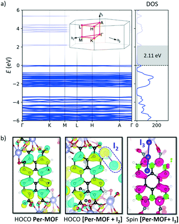
Theoretical calculations were performed to shed light on the structural, electronic and conducting properties of Per-MOF before and after iodine doping (see section 6 in the ESI† for full computational details). The minimum-energy crystal structure of Per-MOF was obtained upon full ionic and lattice relaxation at the PBEsol level of theory without symmetry constraints. Lattice parameters for the optimized crystal structure are in good accord with the experimental X-ray data (Table S3, ESI†).Band structure calculations were performed on the first Brillouin zone of the reciprocal space corresponding to the P![[3 with combining macron]](https://www.rsc.org/images/entities/char_0033_0304.gif) space group. The electronic band structure of the evacuated Per-MOF framework displays flat bands along the full k-path (Fig. 4a), suggesting a hopping mechanism in case of efficient charge transport. The highest-occupied (HOCO) and lowest-unoccupied (LUCO) crystal orbitals are localized over the PTC moieties (Fig. 4b and S21†), and their shape resembles the typical frontier molecular orbitals of the perylene molecule.49
space group. The electronic band structure of the evacuated Per-MOF framework displays flat bands along the full k-path (Fig. 4a), suggesting a hopping mechanism in case of efficient charge transport. The highest-occupied (HOCO) and lowest-unoccupied (LUCO) crystal orbitals are localized over the PTC moieties (Fig. 4b and S21†), and their shape resembles the typical frontier molecular orbitals of the perylene molecule.49
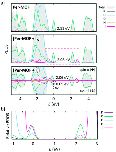
Iodine doping was modelled by placing one iodine molecule per unit cell in the framework pore, according to the stoichiometry derived experimentally (1 I2 molecule per 3 perylene units). The minimum-energy crystal structure indicates that iodine favourably interacts with the framework (Fig. S22, ESI†), displaying I2⋯perylene intermolecular contacts in the range of 3.3–4.0 Å, and a short I2⋯O(COO−) interaction (2.43 Å). Upon iodine doping, electronic structure calculations predict a flat-band profile with a small reduction of the bandgap from 2.11 to 2.08 eV (Fig. 4a and S23a†), in good accord with the experimental evidence (see above). Atom-projected density of states (PDOS) calculations indicate that the frontier molecular orbitals of I2 are close in energy to the HOCO and LUCO of Per-MOF, slightly shifted away from the bandgap (Fig. 5a; HOCO−3 and LUCO+3 in Fig. S24, ESI†). However, close inspection of the crystal orbital topology evidences an appreciable contribution of I2 to HOCO (Fig. 4b). Relative PDOS confirms the active role of iodine in the frontier crystal orbitals of [Per-MOF + I2] (Fig. 5b).
According to the experimental evidence, iodine doping promotes the formation of the perylene radical cation due to oxidation by I2 and formation of I3− species. Theoretical calculations indicate that in the presence of I3 the spontaneous oxidation of perylene moiety and formation of anion I3− occurs. I3− favourably interacts with the framework, with short I⋯K (3.5–3.9 Å) and I⋯H (3.2–3.6 Å) contacts (Fig. S25, ESI†). The spin density calculated for [Per-MOF + I3] predicts the localization of an unpaired electron on one perylene moiety of the unit cell (Fig. 4b), whose accumulated charge (Δq) increases +0.90e with respect to Per-MOF, whereas the I3 net charge is −0.70e. These results therefore confirm the formation of both a perylene radical cation and I3−. As a result, a half-empty valence band results (spin-β bandgap of 0.09 eV; Fig. 5a), with a significant contribution of the I3− species to HOCO-β (see Fig. S26, ESI†).
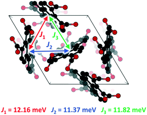
To get insight into the conducting properties of Per-MOF upon iodine doping (perylene cation formation), the electronic coupling (J) for hole carriers between perylene pairs was evaluated from molecular calculations. Recall that Per-MOF displays a band structure with flat states (Fig. 4a and S23†), which points towards a hopping regime as the dominant charge-transport mechanism.6,50 Moreover, the inefficient herringbone stacking pattern of PTC moieties in Per-MOF is typical of organic semiconductors reported to show a hopping charge transport.51–53 The size of the charge-carrier polaron species was estimated from the spin density contours calculated for perylene oligomers extracted from the crystal structure of Per-MOF and incorporating an oxidized perylene unit. The polaron is shown to be localized over few (1 or 2) perylene units (Fig. S27, ESI†), thus supporting a hopping mechanism. The J values for the three perylene interacting pairs in the Per-MOF unit cell were calculated with very similar values, as expected from the experimental P![[3 with combining macron]](https://www.rsc.org/images/entities/char_0033_0304.gif) symmetry (Fig. 6), with a mean J value of 12 meV (a relatively small coupling as anticipated by the inefficient herringbone arrangement). Moving to the perylene pairs of [Per-MOF + I2] and [Per-MOF + I3] (see section 6 in the ESI† for details), the electronic couplings are comparable to Per-MOF (mean J values of 11 and 9 meV, respectively; Table S4†), therefore suggesting a negligible structural effect of the iodine inclusion on the electronic communication between perylenes. On the other hand, the electronic effect of the iodine doping was assessed by calculating the lowest-lying excited states of perylene-guest dimers under the time-dependent density functional theory,54 and considering the different charged species available (see the ESI†). Interestingly, several charge-transfer (CT) states are predicted in the low-energy range, from very low to moderate probability (oscillator strength, f), and described by a net one-electron transfer from one moiety to the other (see Fig. S28†). For example, a charge-transfer state from perylene to I2 is predicted at 0.71 eV and with a f = 0.029, whereas a CT from I3− to [perylene]+ is calculated at 0.72 eV with a f = 0.001. As the conductivity depends on the charge mobility and carrier concentration, promoting hole carriers through perylene radical cations upon iodine doping, with the additional benefit of boosting perylene–perylene communication through guest-promoted charge transfer excitations, is expected to enhance significantly the electrical charge transport of Per-MOF.
symmetry (Fig. 6), with a mean J value of 12 meV (a relatively small coupling as anticipated by the inefficient herringbone arrangement). Moving to the perylene pairs of [Per-MOF + I2] and [Per-MOF + I3] (see section 6 in the ESI† for details), the electronic couplings are comparable to Per-MOF (mean J values of 11 and 9 meV, respectively; Table S4†), therefore suggesting a negligible structural effect of the iodine inclusion on the electronic communication between perylenes. On the other hand, the electronic effect of the iodine doping was assessed by calculating the lowest-lying excited states of perylene-guest dimers under the time-dependent density functional theory,54 and considering the different charged species available (see the ESI†). Interestingly, several charge-transfer (CT) states are predicted in the low-energy range, from very low to moderate probability (oscillator strength, f), and described by a net one-electron transfer from one moiety to the other (see Fig. S28†). For example, a charge-transfer state from perylene to I2 is predicted at 0.71 eV and with a f = 0.029, whereas a CT from I3− to [perylene]+ is calculated at 0.72 eV with a f = 0.001. As the conductivity depends on the charge mobility and carrier concentration, promoting hole carriers through perylene radical cations upon iodine doping, with the additional benefit of boosting perylene–perylene communication through guest-promoted charge transfer excitations, is expected to enhance significantly the electrical charge transport of Per-MOF.
The evolution of the Per-MOF experimental optical properties upon iodine doping was rationalized through theoretical modelling. Molecular calculations were performed on the lowest-lying singlet excited states of H4PTCA, radical H4PTCA cation, I2 and I3− at the PBE0 level. Simulated absorption and emission spectra including vibrational resolution of H4PTCA are predicted with a mirror symmetry and a Stokes shift of 0.05 eV (Fig. S29a, ESI†). The most intense 0–0 PTC emission peak is predicted at 523 nm, in good accord with the experimental data recorded for Per-MOF (528 nm). Note that the excitonic coupling between perylenes in the framework is calculated to be ca. +45 meV (see the ESI† for computational details), indicating a H-type stacking interaction in the herringbone motif. This value is in line with the experimental blue-shift of the PTC emission band going from H4PTCA molecule to Per-MOF (+52 meV). Molecular iodine I2 is predicted with two degenerate singlet excited states S1 and S2 at 2.40 eV (517 nm, Table S5, ESI†), and supports the increase of the absorption features of H4PTCA in the 500 nm region upon iodine doping (Fig. S17, ESI†). Otherwise, the triiodide system is predicted with two degenerate S3 and S4 excited states at 3.47 eV (357 nm), which account for the increasing absorption band experimentally recorded at 360 nm upon doping (Fig. S17, ESI†). Whereas the bright electronic transition in cationic H4PTCA (doublet D9 0–0 transition at 518 nm, Fig. S29b, ESI†) is predicted in the same energy range as for neutral H4PTCA (singlet S1 0–0 transition at ca. 504 nm, Fig. S29a, ESI†), emission is expected to occur from S1, which upon relaxation is calculated at 770 nm, in good accord with the literature.55 The increase of the emission feature at 530 nm in Per-MOF upon doping is therefore ascribed to the radiative emission of I3−, experimentally registered at 532 nm (Fig. S18, ESI†).
Electrical conductivity
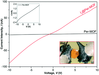
To investigate the electrical conductivity of Per-MOF and I2@Per-MOF, transport measurements were performed using two-contact single-crystal devices, at room temperature (300 K). A representative I–V curve of the measured set of independent crystals is shown in Fig. 7, and individual device details can be found in Table S6 and Fig. S30 (ESI†). The electrical conductivity was measured along the ab plane as perylenes are stacked along the a-axis (see crystal indexing in Fig. S31†). It was not possible to measure the conductivity along the ac plane due to the small thickness of the crystals. Per-MOF and I2@Per-MOF samples present conductivities of the order of 10−8 and 10−5–10−7 S cm−1, respectively (Table S6†), with an average increase of two orders of magnitude for the doped I2@Per-MOF, and the best performing device achieving a value of 1.1 × 10⁻⁵ S cm−1. Both silver epoxy and carbon paste were tested as contacts, but the best ohmic I–V behaviour was achieved when using carbon paste-based devices, as previously reported.56 The I–V is not completely linear due to defects in the crystal surface (Fig. S32†), which lead to asymmetric contacts. This effect is not observed in the I–V curves of the pressed pellets, as these present a more uniform surface morphology. These conductivity values are slightly higher than the value of a recently described perylene diimide (PDI)-based MOF (∼10−7 S cm−1),57 and similar to those of a family of oxidized tetrathiafulvalene-alkali metal MOFs (∼10−5 S cm−1) measured as pressed pellets.36 In order to further understand the importance of the diffusion process of iodine molecules through the micropores, Per-MOF crystals were also oxidized by exposure to I2 vapours for 24 h. However, the conductivity of I2@Per-MOF obtained by this process was lower than that obtained by iodine doping in solution (Fig. S33, ESI†), indicating a more efficient diffusion in solution. Finally, a ∼10% reversible increase of the electrical current was observed for I2@Per-MOF upon white-light irradiation (Fig. S34, ESI†), suggesting that this type of doped perylene-based MOFs hold much potential to exhibit photoconductivity as theoretically predicted in recent reports.58,59Conclusions
In summary, we have reported the first evidence of increased conductivity in a perylene-based MOF upon iodine doping. This conductivity is ascribed to the partial oxidation of the perylene ligands, as witnessed by EPR and emission spectroscopy, and supported by theoretical calculations. The charge transport is described by means of a through-space hopping mechanism along the herringbone perylene packing, with highest conductivities of the order of 10−5 S cm−1 measured in two-contact single-crystal devices. Current research is focused on the design of extended perylene-based ligands to increase the MOFs porosity, allowing the encapsulation of larger electron-acceptor (doping) molecules. We highlight the potential of perylene building blocks for the design of electrically conductive and photoresponsive MOFs. In this direction, one of the main challenges is the construction of doped perylene-based MOFs in which electroactive ligands are arranged showing different stacking modes (e.g., face-to-face π-stacking) in order to modulate their electrical properties.Author contributions
G. V. synthesised and characterised the doped material. A. P. and H. A. carried out and analysed the electrical measurements. A. R. D. and D. C. L. analysed the crystal structure. M. A. H.-R. carried out and analysed the optical measurements. M. E.-R., E. O. and J. C. performed the theoretical calculations and wrote the theoretical section. M. I. and L. M. carried out the gas sorption measurements. M. S. carried out the electrochemical measurements and conceived the research. G. V. and M. S. drafted the first version of the manuscript. All authors revised and contributed to the manuscript.Conflicts of interest
There are no conflicts to declare.Acknowledgements
This work was developed within the scope of the project CICECO-Aveiro Institute of Materials, Grants UIDB/50011/2020 and UIDP/50011/2020, financed by national funds through the FCT/MEC and when appropriate co-financed by FEDER under the PT2020 Partnership Agreement. We thank FCT for funding the project PTDC/QUI-ELT/2593/2021. We acknowledge Spanish government (PID2020-119748GA-I00, funded by MICIN/AEI/10.13039/501100011033, and the Maria de Maeztu CEX2019-000919-M grant) and Generalitat Valenciana (GV/2021/027, GVPROMETEO2020-077). G. V. is grateful to FCT for a PhD grant (2020.08520.BD). A. P. is grateful to FCT for a PhD grant (2020.06159.BD). FCT is also acknowledged by M. I. for a Junior Researcher Position (CEECIND/00546/2018). We thank Celeste Azevedo for TGA and Raman measurements. We thank Prof. Luís Carlos and Prof. Carlos Brites (Phantom-G) for the use and assistance with spectrofluorimeter and quantum yield equipment. We thank Prof. Nikolai Sobolev for EPR measurements.Notes and references
- M. Dincă and J. R. Long, Chem. Rev., 2020, 120, 8037–8038 CrossRef.
- G. Maurin, C. Serre, A. Cooper and G. Férey, Chem. Soc. Rev., 2017, 46, 3104–3107 RSC.
- M. Souto, K. Strutyński, M. Melle-Franco and J. Rocha, Chem. – Eur. J., 2020, 26, 10912–10935 CrossRef CAS PubMed.
- M. D. Allendorf, R. Dong, X. Feng, S. Kaskel, D. Matoga and V. Stavila, Chem. Rev., 2020, 120, 8581–8640 CrossRef CAS.
- L. S. Xie, G. Skorupskii and M. Dincă, Chem. Rev., 2020, 120, 8536–8580 CrossRef CAS.
- J. Calbo, M. J. Golomb and A. Walsh, J. Mater. Chem. A, 2019, 7, 16571–16597 RSC.
- B. Ding, M. B. Solomon, C. F. Leong and D. M. D'Alessandro, Coord. Chem. Rev., 2021, 439, 213891 CrossRef CAS.
- E. Zojer and C. Winkler, J. Phys. Chem. Lett., 2021, 12, 7002–7009 CrossRef CAS PubMed.
- S. S. Park, E. R. Hontz, L. Sun, C. H. Hendon, A. Walsh, T. Van Voorhis and M. Dincǎ, J. Am. Chem. Soc., 2015, 137, 1774–1777 CrossRef CAS PubMed.
- J. Castells-Gil, S. Mañas-Valero, I. J. Vitórica-Yrezábal, D. Ananias, J. Rocha, R. Santiago, S. T. Bromley, J. J. Baldoví, E. Coronado, M. Souto and G. Mínguez Espallargas, Chem. – Eur. J., 2019, 25, 12636–12643 CrossRef CAS PubMed.
- L. S. Xie, E. V. Alexandrov, G. Skorupskii, D. M. Proserpio and M. Dincă, Chem. Sci., 2019, 10, 8558–8565 RSC.
- D. Chen, H. Xing, Z. Su and C. Wang, Chem. Commun., 2016, 52, 2019–2022 RSC.
- S. Goswami, D. Ray, K. Otake, C. Kung, S. J. Garibay, T. Islamoglu, A. Atilgan, Y. Cui, C. J. Cramer, O. K. Farha and J. T. Hupp, Chem. Sci., 2018, 9, 4477–4482 RSC.
- G. Haider, M. Usman, T.-P. Chen, P. Perumal, K.-L. Lu and Y.-F. Chen, ACS Nano, 2016, 10, 8366–8375 CrossRef CAS PubMed.
- L. Qu, H. Iguchi, S. Takaishi, F. Habib, C. F. Leong, D. M. D. Alessandro, T. Yoshida, H. Abe, E. Nishibori and M. Yamashita, J. Am. Chem. Soc., 2019, 141, 6802–6806 CrossRef CAS.
- X. Kuang, S. Chen, L. Meng, J. Chen, X. Wu, G. Zhang, G. Zhong, T. Hu, Y. Li and C. Z. Lu, Chem. Commun., 2019, 55, 1643–1646 RSC.
- J. Y. Koo, Y. Yakiyama, G. R. Lee, J. Lee, H. C. Choi, Y. Morita and M. Kawano, J. Am. Chem. Soc., 2016, 138, 1776–1779 CrossRef CAS PubMed.
- R. Haldar, M. Kozlowska, M. Ganschow, S. Ghosh, M. Jakoby, H. Chen, F. Ghalami, W. Xie, S. Heidrich, Y. Tsutsui, J. Freudenberg, S. Seki, I. A. Howard, B. S. Richards, U. H. F. Bunz, M. Elstner, W. Wenzel and C. Wöll, Chem. Sci., 2021, 12, 4477–4483 RSC.
- M. H. Zeng, Q. X. Wang, Y. X. Tan, S. Hu, H. X. Zhao, L. S. Long and M. Kurmoo, J. Am. Chem. Soc., 2010, 132, 2561–2563 CrossRef CAS.
- Z. Yin, Q. X. Wang and M. H. Zeng, J. Am. Chem. Soc., 2012, 134, 4857–4863 CrossRef CAS PubMed.
- H.-Y. Wang, J.-Y. Ge, C. Hua, C.-Q. Jiao, Y. Wu, C. F. Leong, D. M. D'Alessandro, T. Liu and J.-L. Zuo, Angew. Chem., Int. Ed., 2017, 56, 5465–5470 CrossRef CAS PubMed.
- J. Su, S. Yuan, H.-Y. Wang, L. Huang, J.-Y. Ge, E. Joseph, J. Qin, T. Cagin, J.-L. Zuo and H.-C. Zhou, Nat. Commun., 2017, 8, 2008 CrossRef PubMed.
- H. Akamatu, H. Inokuchi and Y. Matsunaga, Nature, 1954, 173, 168–169 CrossRef.
- P. Batail, Chem. Rev., 2004, 104, 4887–4890 CrossRef CAS.
- F. G. Brunetti, R. Kumar and F. Wudl, J. Mater. Chem., 2010, 20, 2934–2948 RSC.
- M. Almeida and R. Henriques, in Handbook of organic conductive molecules and polymers, Wiley, New York, 1997, pp. 87–149 Search PubMed.
- M. Clemente-León, E. Coronado, C. Giménez-Saiz, C. J. Gómez-García, E. Martínez-Ferrero, M. Almeida and E. B. Lopes, J. Mater. Chem., 2001, 11, 2177–2181 RSC.
- M. Majumder, P. Sheath, J. I. Mardel, T. G. Harvey, A. W. Thornton, A. Gonzago, D. F. Kennedy, I. Madsen, J. W. Taylor, D. R. Turner and M. R. Hill, Chem. Mater., 2012, 24, 4647–4652 CrossRef CAS.
- C. Dietl, H. Hintz, B. Rühle, S. J. Auf Der Ginne, H. Langhals and S. Wuttke, Chem. – Eur. J., 2015, 21, 10714–10720 CrossRef CAS PubMed.
- L. D. Tran, J. Ma, A. G. Wong-Foy and A. J. Matzger, Chem. – Eur. J., 2016, 22, 5509–5513 CrossRef CAS PubMed.
- N. Sikdar, D. Dutta, R. Haldar, T. Ray, A. Hazra, A. J. Bhattacharyya and T. K. Maji, J. Phys. Chem. C, 2016, 120, 13622–13629 CrossRef CAS.
- J. M. Seco, E. San Sebastián, J. Cepeda, B. Biel, A. Salinas-Castillo, B. Fernández, D. P. Morales, M. Bobinger, S. Gómez-Ruiz, F. C. Loghin, A. Rivadeneyra and A. Rodríguez-Diéguez, Sci. Rep., 2018, 8, 1–10 CAS.
- J. Li, S. Yuan, J. S. Qin, L. Huang, R. Bose, J. Pang, P. Zhang, Z. Xiao, K. Tan, A. V. Malko, T. Cagin and H. C. Zhou, ACS Appl. Mater. Interfaces, 2020, 12, 26727–26732 CrossRef CAS PubMed.
- F. Mo, Q. Han, M. Chen, H. Meng, J. Guo and Y. Fu, Nanoscale, 2021, 13, 16244–16250 RSC.
- J.-M. Wang, L.-Y. Yao, W. Huang, Y. Yang, W.-B. Liang, R. Yuan and D.-R. Xiao, ACS Appl. Mater. Interfaces, 2021, 13, 44079–44085 CrossRef CAS PubMed.
- S. Zhang, D. K. Panda, A. Yadav, W. Zhou and S. Saha, Chem. Sci., 2021, 12, 13379–13391 RSC.
- M. Huang, U. Schilde, M. Kumke, M. Antonletti and H. Cölfen, J. Am. Chem. Soc., 2010, 132, 3700–3707 CrossRef CAS PubMed.
- H. Kojima and T. Mori, Bull. Chem. Soc. Jpn., 2011, 84, 1049–1056 CrossRef CAS.
- N. J. Hestand and F. C. Spano, Acc. Chem. Res., 2017, 50, 341–350 CrossRef CAS PubMed.
- B. Chen, Z. P. Lv, C. F. Leong, Y. Zhao, D. M. D'alessandro and J. L. Zuo, Cryst. Growth Des., 2015, 15, 1861–1870 CrossRef CAS.
- C. Wang, W. Tang, Z. Yao, B. Cao and C. Fan, Chem. Commun., 2019, 55, 1801–1804 RSC.
- Y. Jiang, L. Lu, M. Yang, C. Zhan, Z. Xie, F. Verpoort and S. Xiao, Polym. Chem., 2013, 4, 5612–5620 RSC.
- C. W. Kung, T. C. Wang, J. E. Mondloch, D. Fairen-Jimenez, D. M. Gardner, W. Bury, J. M. Klingsporn, J. C. Barnes, R. Van Duyne, J. F. Stoddart, M. R. Wasielewski, O. K. Farha and J. T. Hupp, Chem. Mater., 2013, 25, 5012–5017 CrossRef CAS.
- S. L. Hsu, A. J. Signorelli, G. P. Pez and R. H. Baughman, J. Chem. Phys., 1978, 69, 106–111 CrossRef CAS.
- P. H. Svensson and L. Kloo, Chem. Rev., 2003, 103, 1649–1684 CrossRef CAS PubMed.
- J. Chang, H. Li, J. Zhao, X. Guan, C. Li, G. Yu, V. Valtchev, Y. Yan, S. Qiu and Q. Fang, Chem. Sci., 2021, 12, 8452–8457 RSC.
- A. Wolter, U. Fasol, R. Jäppelt and E. Dormann, Phys. Rev. B: Condens. Matter Mater. Phys., 1996, 54, 12272–12282 CrossRef CAS PubMed.
- S. V. Kireev and S. L. Shnyrev, Laser Phys., 2015, 25, 075602 CrossRef.
- J. Merz, A. Steffen, J. Nitsch, J. Fink, C. B. Schürger, A. Friedrich, I. Krummenacher, H. Braunschweig, M. Moos, D. Mims, C. Lambert and T. B. Marder, Chem. Sci., 2019, 10, 7516–7534 RSC.
- J. L. Mancuso, A. M. Mroz, K. N. Le and C. H. Hendon, Chem. Rev., 2020, 120, 8641–8715 CrossRef CAS PubMed.
- R. S. Sánchez-Carrera, P. Paramonov, G. M. Day, V. Coropceanu and J.-L. Brédas, J. Am. Chem. Soc., 2010, 132, 14437–14446 CrossRef PubMed.
- A. Köhler and H. Bässler, Electronic Processes in Organic Semiconductors: An Introduction, Wiley-VCH, Weinheim, 2015 Search PubMed.
- H. Oberhofer, K. Reuter and J. Blumberger, Chem. Rev., 2017, 117, 10319–10357 CrossRef CAS PubMed.
- C. Adamo and D. Jacquemin, Chem. Soc. Rev., 2013, 42, 845–856 RSC.
- C. Joblin, F. Salama and L. Allamandola, J. Chem. Phys., 1995, 102, 9743–9745 CrossRef CAS.
- L. Sun, S. S. Park, D. Sheberla and M. Dincă, J. Am. Chem. Soc., 2016, 138, 14772–14782 CrossRef CAS PubMed.
- P. I. Scheurle, A. Biewald, A. Mähringer, A. Hartschuh, D. D. Medina and T. Bein, Small Struct., 2022, 2100195 CrossRef CAS.
- S. Chong, D. T. Park and J. Kim, J. Phys. Chem. C, 2021, 125, 10198–10206 CrossRef CAS.
- S. Ahmad, J. Liu, C. Gong, J. Zhao and L. Sun, ACS Appl. Energy Mater., 2018, 1, 249–253 CrossRef CAS.
Footnotes |
| † Electronic supplementary information (ESI) available: General methods and materials, synthesis of H4PTCA and Per-MOF, iodine doping and characterisation of I2@Per-MOF, quantum-chemical calculations. See DOI: https://doi.org/10.1039/d2me00108j |
| ‡ These authors contributed equally to this work. |
| This journal is © The Royal Society of Chemistry 2022 |

