 Open Access Article
Electrochemistry under confinement
Maximilian
Jaugstetter†
,
Niclas
Blanc†
,
Markus
Kratz
 and
Kristina
Tschulik
 *
*
Analytical Chemistry II, Faculty of Chemistry and Biochemistry, Ruhr University Bochum, Bochum, Germany. E-mail: kristina.tschulik@rub.de
First published on 11th March 2022
Abstract
Although the term ‘confinement’ regularly appears in electrochemical literature, elevated by continuous progression in the research of nanomaterials and nanostructures, up until today the various aspects of confinement considered in electrochemistry are rather scattered individual contributions outside the established disciplines in this field. Thanks to a number of highly original publications and the growing appreciation of confinement as an overarching link between different exciting new research strategies, ‘electrochemistry under confinement’ is the process of forming a research discipline of its own. To aid the development a coherent terminology and joint basic concepts, as crucial factors for this transformation, this review provides an overview on the different effects on electrochemical processes known to date that can be caused by confinement. It also suggests where boundaries to other effects, such as nano-effects could be drawn. To conceptualize the vast amount of research activities revolving around the main concepts of confinement, we define six types of confinement and select two of them to discuss the state of the art and anticipated future developments in more detail. The first type concerns nanochannel environments and their applications for electrodeposition and for electrochemical sensing. The second type covers the rather newly emerging field of colloidal single entity confinement in electrochemistry. In these contexts, we will for instance address the influence of confinement on the mass transport and electric field distributions and will link the associated changes in local species concentration or in the local driving force to altered reaction kinetics and product selectivity. Highlighting pioneering works and exciting recent developments, this educational review does not only aim at surveying and categorizing the state-of-the-art, but seeks to specifically point out future perspectives in the field of confinement-controlled electrochemistry.
1. Introduction
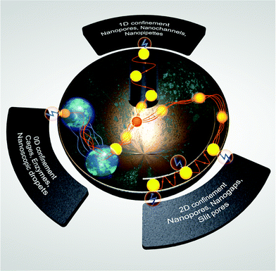
In the advent of a transition towards renewable energies, sustainable chemistry, smart sensing and personalized medicine, electrochemistry is gaining more attention as a technology enabler and cross-disciplinary research area. On the one hand, it allows us to directly utilise electricity from renewable sources, or to store this energy in the form of chemical bonds. On the other hand, it allows us to selectively and quantitatively detect target species in highly complex surroundings in real time and in a miniaturized, minimally-invasive manner. Jointly with the fact that current or potential are easy-to-process sensor readouts and easy-to-adjust process parameters, the application of electrochemical techniques is beneficial for sensing and energy applications alike. The vast possibilities have driven researchers to develop novel electrocatalyst or sensing materials, which fulfil the necessary requirements of activity, longevity and recyclability. While doing so, the focus was often put on complex three-dimensional structures with substructures in the nanometre range to maximize either surface area or intrinsic activity/sensitivity, by exposing special active sites (Fig. 1).With miniaturization and increasing complexity, additional effects, showing deviations from macroscopic models, have been reported. These effects can occur due to different behaviours at the nanoscale, which can be summarized as “nano-effects” or because of additional interfaces causing a confinement that affects the electrochemical process, as “confinement effects”. Provided that the latter is much less explored and, hence, provides large potential for disruptive technological breakthroughs in the near future, we will shine light on some of the many exciting examples of such confinement effects on electrochemical processes.
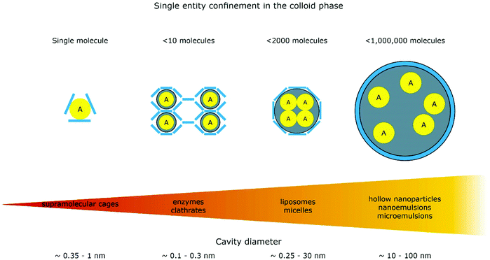
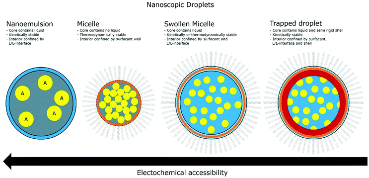
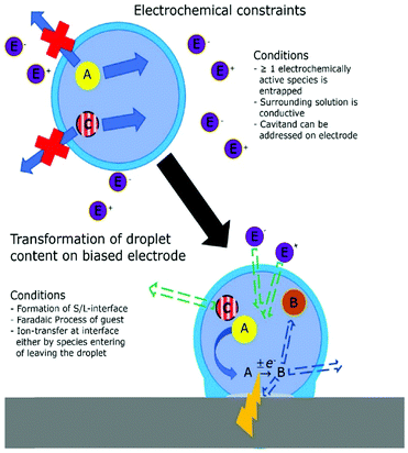
This review consists of four main parts. In the first part, we introduce a classification system enabling a direct comparison between confinement-related effects and propose a structured approach for their identification and characterisation based on theoretical techniques and experimental studies. We will highlight different instances where a physical confinement alters electrochemical behaviour with the focus on nanochannel systems in the second part, electrochemical sensing in the third part and on micro- and nanoemulsions in the fourth part.
As an electrode can be defined as a system that contains at least one interface between ionic and electronic conductors, which are not connected in series, and all electrochemical reactions take place at electrodes, electrochemical behaviour is defined by interfacial processes. If these are altered by the introduction of a confined space, it can be considered a confinement induced effect, or confinement effect. Since there is no established definition what may be considered as confinement effects in electrochemical literature, we highlight different instances where these requirements are met.
Herein, we want to present electrochemical confinement effects based on their influence on classical electrochemical parameters. Those include, but are not limited to the mass transport at an electrode, the behaviour of the reactant in vicinity of an electrode and the interface properties themselves. In this review, we consider an effect confinement-related, if one or more of the aforementioned properties are significantly altered due to the presence of an additional interface, resulting in a behaviour that deviates from classical electrochemistry.
1.1. Confinement in electrochemical literature
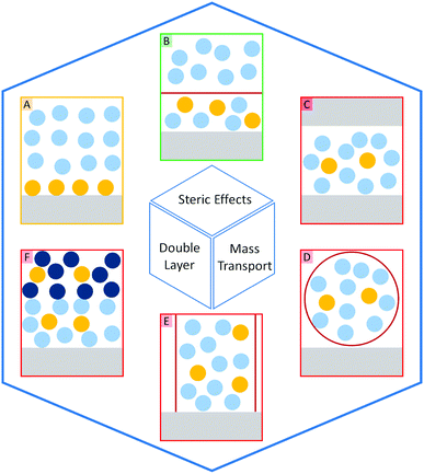
The introduction of confining interfaces into electrochemical systems can alter several different system properties, depending on the nature of the involved interfaces and confined spaces. Therefore, two natural paths for a classification of confinement effects are by dimension of confined spaces or by their influence on the electrochemical system. In this section, we will focus on the different confined spaces that play a role in modern electrochemistry.Confined spaces may be classified based on their dimension, which corresponds to the degrees of freedom that a reacting species experiences in vicinity to an electrode. For sure, this classification is not universal and combinations of or outliers from these types of confinement may occur. The first class, possessing the least degrees of freedom contains surface-confined species (Fig. 2A), where static interactions between the adsorbate and the electrode severely limit their translational freedom. This is the case for e.g., electrochemically generated monolayers via under potential deposition (UPD) or chemically self-assembled monolayers (SAMs). The second type involves solvated reactants, whose movements are limited by confining barriers, such as in 2D-layered materials or nanotubes (Fig. 2B). The third type consists of cases, where the solvated species can move in three dimensions, but are confined in spaces in the nanometre range (Fig. 2C–F). This third type includes mesoporous materials and reverse micelles (Table 1).
1.2. The types of confinement
| Mass transport | Double layer | Steric effects | |
|---|---|---|---|
| Surface-confinement | — | 3.4 | 3.4 |
| 2D-structures | 3.2, 3.3.2 | 3.3.1, 3.3.2, 3.4 | 3.4 |
| Nanoreactor | 4.4.2, 4.4.4 | 4.4.2, 4.4.4 | 4.4.2 |
| 1D channel | 2.2.1, 3.3.1, 3.4, 3.5 | 2.2.2, 3.3.1 | 2.2.2, 2.3, 3.4, 3.5 |
| Liquid–liquid interface | 4.4.3 | 4.4.3 | — |
This leads to a hopping behaviour, where the silver nanoparticles enter and leave the electron transfer plane several times,3 leading to several, distinct and incomplete oxidation events, also reported in previous publications.4–7 While intermediate interactions between silver nanoparticles and gold electrodes allow a single step oxidation of the silver surface, strong interactions between Au and AgOx lead to a permanent chemisorption of the particles onto the surface. This behaviour was shown experimentally by adjusting the pH to alkaline conditions during silver nanoparticle impacts, as dwell times and transferred charge significantly increased compared to nanoparticles of similar sizes in neutral media. The highly increased charge transfer was attributed to a complete faradaic transformation of the Ag nanoparticles to AgOx.
Besides nano impact experiments, Katz et al.8 presented another mode of surface confinement: the reversible surface confinement of nanoparticles triggered by an external magnetic field. The magneto switchable control of an electrochemical reaction by adsorbing and desorbing of a modified magnetic nanoparticle thin film on the electrode was shown to drastically modify electrode properties and the reaction pathway. Magnetic nanoparticles modified alkyl chains could be confined to the surface of the electrode by an external magnetic field, resulting in a complete blocking of diffusive electrochemical processes, which greatly enhances the switch performance with respect to permanently immobilized nanoparticles. Further modifications of the nanoparticles with hydrophobic molecules allowed to separate different electrochemical processes at the surface or alter the reaction mechanism by modification of diffusional processes between solvated species and the electrode.
The influence of confinement onto catalytic reactions is strongly related to adsorption and desorption of intermediate reaction products. In their communication, Doyle et al.12 demonstrate the geometric influence of a nanochannel on these process parameters. Using DFT calculations, the diameter of a RuO2 nanochannel has been related to the adsorption energies of intermediates of the oxygen evolution reaction, which shows an energetic minimum at around 0.6 nm. Their calculations propose a correlation of this minimum with stabilizing interactions between HOO* and the channel walls, while the other intermediates remain unaffected, indicating the possible breaking of limiting scaling relations for this system. Further investigations of the mechanism suggest that the effect is caused by formation of stabilizing hydrogen bonds between the HOO* intermediate and the oxygen terminated opposite channel wall. The study further discusses the influence of nanochannel confinement onto the catalytic performance of different catalyst materials in regard to the pore diameter and the rate determining step.
As the volumes inside porous materials are very small, the forming electrical double layer (EDL) and therefore the electric field will overlap. Sen et al.18 investigated this effect for the electrochemical reduction of CO2 in copper nanofoams where the forming products differ significantly from those formed at a comparable macroscopic system. This overlap in the EDL (Sections 1.3.2 and 3.3.1) leads to an inaccessibility of the inner pore surface area even at high overpotentials. Comprehensive reviews, discussing the effects of Knudsen diffusion and EDL overlap in nanoconfined spaces were presented by White and co-workers19 for single entity electrochemistry and by Seo et al.20 for catalytic considerations. When investigating the EDL overlap and comparing the confinement influence between aqueous and ionic liquid-based electrolytes, drastic differences are observed. The review article of Avid et al.21 additionally considers the special interactions of ionic liquids in nano-confinement and its influence on the EDL. Several recent research sources discussing the influence of overlapping EDLs onto ion transport and the interplay of complex ion interactions at the electrode are highlighted.
The usage of porous catalyst materials in electrochemical applications is a highly discussed topic in literature, as these materials grant similar high surface areas compared to other nanocatalyst systems. In contrast to electrode-supported nanoparticles, these systems do not suffer from influences of support or capping agent effects and particle aggregation during catalysis, as summarized in a review by Luc et al.22 For a deeper understanding in the fabrication, the applications and drawbacks of porous electrode materials, we refer to the works of Fu et al.23 for nanopore electrode arrays and Sun et al.24 for hierarchical 3D electrodes, as our work focuses more on the concepts of confined space and its implications on electrochemical signals.
Those two examples showcase that confinement effects in electrochemistry are diverse, as they may originate from the alteration of at least one process governing electrochemical reactions. Another form of nanoscopic confinement is found in bipolar electrochemistry. There, the confinement of a strong electric field gradient on a nanoscopic object, such as a nanorod or nanoparticle25 is leading to locally different electrode potentials, enabling, e.g. directed electrochemical growth.26 Stockmann et al. demonstrated that Pt NPs, can be used in bipolar electrochemistry to mediate electron transfer trough the interface between two immiscible liquids.27 The authors showed how nanoparticles simultaneously oxidized ferrocene in the organic phase, while reducing oxygen in the aqueous phase during their transition through the interface.
1.3. The underlying physical processes
Whenever a measurable confinement effect, irrespective of dimension, alters the behaviour of an electrochemical experiment, the presence of the confining boundary changes at least one physical parameter. In this section, we will briefly introduce the most relevant parameters confinement effects were reported for, how they can be altered and how this can affect electrochemical processes. In the next sections we will discuss how these parameters can be identified and analysed theoretically.As an example, if two compartments are separated by a porous membrane, mass transport is restricted by the specific confinement of the pores. This is directly measurable by an ionic current, which passes through the membrane. Any change in the ionic current, triggered by a target passing through the membrane allows the analysis of this target. This setup allows to investigate target species based on their charge, size and functional sites. Such devices are successfully used for example in DNA sequencing and advance the detection limit of polymeric molecules down to few femto molar.30 While this review focuses on the general concepts of confinement effects in electrochemistry and selected examples of their application, we refer to more specialized reviews for detailed discussion on technical aspects. For instance, implications and applications of nanopore modifications to obtain additional functionality, such as selective ion detection by crown ether modified nanopores31 or switchable hydrophobic rectification by dopamine modified nanopores32 are discussed in reviews focusing on confinement in nanopores, specifically.
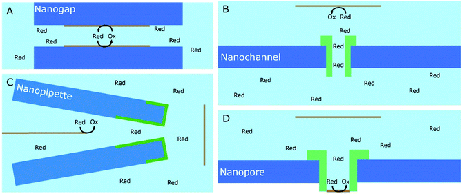
The same mechanism applies for systems of different geometry, such as nano-channels or nano-pipettes. The latter are an essential increment of scanning electrochemical cell microscopy (SECCM) setups, where ion conductance measurements between two separated quasi-reference counter electrodes can be simultaneously measured with a faradaic current from the substrate.33
Since the flux of species through nanoscopic pores can be measured as a change in the ionic current, they are well-suited to detect single entities traversing the channel. Herein, the channel type defines the sensitivity for different species, such as nanoparticles or single biomolecules. Additional examples for mass transport related confinement effects will be reviewed in Sections 2.2.1 and 3.3.1.
1.4. How to identify confinement effects?
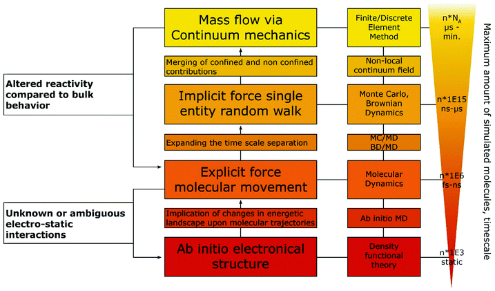
Some difficulties concerning nomenclature and classification of confinement effects emerge, as they often occur in combination with nano-effects. Throughout the cited literature nano-, confinement- and even nanoconfinement-effects were used interchangeably to some extent, depending on the respective field of electrochemistry in which the authors are active. This is attributable to the fact that many nano-effects occur in systems, where confinement effects are also prevalent. Hence, it may be difficult to clarify, whether deviations from macroscopic behaviour occur due to confinement or due to other nano scale effects. For instance, the observation of altered product selectivity at a hollow nanosphere electrocatalyst may be caused by geometric confinement enhancing conversion of one reactant over another, as described above, or by the altered electronic structure of a hollow vs. a filled sphere (nano-effect) influencing species irrespective of their geometry. Thus, it is necessary to evaluate how either of the effects is reflected in the observed electrochemical response. Nowadays, the main contribution to disentangle complex problems may be revealed by computational simulations that have long since seen inclusion into electrochemical research. Due to the various dimensions of confinement effects, different theoretical tools are available to quantify them. To illustrate this, we developed a flow chart (Fig. 3), inspired by Wang et al.15 to discover authentic nano-effects in electrocatalysts employing nanoparticles as catalysts. Our more general adaptation highlights a workflow that incorporates the use of theoretical simulations and control experiments to develop a more quantitative model for possible confinement effects. This flow chart is based on the difference between textbook electrochemical signals and those obtained from experiments in increasingly complex systems. While the former are derived from idealized systems and can be simulated numerically, the latter cannot yet. If the technology for both is available, the flow chart might be taken as a guide for a general iterative process to not only identify whether confinement affects the electrochemical signal, but also determine which underlying physical process is altered and to which extent. To this end, it is important to rationalize the experimental and theoretical tools at hand to date.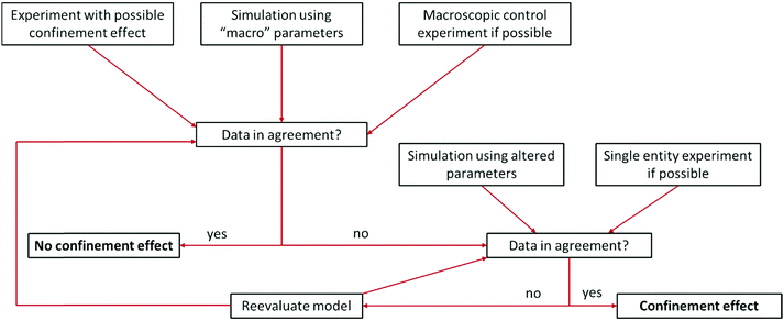 | ||
| Fig. 3 Proposed flow chart to identify confinement effects via combination of experiments and simulation. Inspired by a flow chart to discover nano-effects by Wang et al.15 | ||
Some of the best tools for identification of confinement effects are numerical simulations based on a continuum approach. As they incorporate classical electrochemistry, they have been shown to greatly support or even enable the analysis of experimental results, while providing a means to fit experimental data, based on a state-of-the-art theoretical modelling. The implementation of analytical equations, their coupling with partial differential equations and their numerical solution by either differentiation or integration can be realized by home-written algorithms or readily available commercial software. If the deviation of experiment and simulation cannot be rationalized by classical macroscopic electrochemistry, a possible case of nano- or confinement effects has been identified. If available, macroscopic control experiments, such as experiments with polished macro or single crystal electrodes of well-defined properties can be used. In case of a possible non-classical effect, the situation becomes more difficult, as the complexity of catalyst systems continuously increases. The use of three-dimensional frameworks and hierarchical structures, as well as incorporation of multiple components, is a major challenge for numerical simulations. Thus, assumptions to simplify models as much as possible are usually made to increase simulation efficiency and enable the assessment of meaningful time scales. The same applies if reaction mechanisms are unknown or the continuum approach fails, in which cases the scope of simulations must be adapted, approaching smaller dimensions with simulations that account for the movement of single molecules and the multi body interactions between them. Computational frameworks accounting for these interactions can be generalized into three main categories, differentiated by the number of variables that have to be computed and the depth of molecular information yielded by such simulations (Fig. 4). The first category explicitly calculates the trajectories of the molecules, or supramolecular entities under investigation, while solvent molecules, temperature and density changes are approximated by a continuum field and interparticle interactions are calculated by simple distance-to-interaction relations, like the Lennart Jones potential. On the one hand, kinetic Monte Carlo simulations follow this approach by randomly generating new molecular positions with respect to the initial position, utilizing acceptance criteria to settle for a physically meaningful transition. On the other hand, Brownian Dynamics simulations use Langevin Dynamics, to calculate molecular trajectories from initial velocities and the applied static forces.37 Both simulation methods work in time ranges between nano seconds and several micro seconds and can calculate volumes up to 100 μm3, while Monte Carlo (MC) approaches are computationally less demanding and thus, applicable to even larger systems and longer timescales, Brownian Dynamics (BD) simulations allow to simulate the evolution of the system over real time steps, with a physical meaning.38 Due to rather uncomplicated application of charges and electric fields within the BD approach, it poses a suitable computational backbone to investigate the behaviour of single entities under the influence of a change in the electric field.
Utilizing BD, Goldt et al.39 simulated the movement of single nanoparticles, through a nanochannel of similar size under the influence of different electric fields imposed within the channel, while Grün et al.40 investigated the influence of molecular ionisation at the electrode on the structure of the electrical double layer. The second category accounts for the trajectories of every involved molecule and atom, utilizing force fields to describe electrostatic inter-, and intraparticle interactions. Classical molecular dynamics (MD) approaches fill this category, allowing simulated timescales between pico- and nanoseconds and unit cells of up to 100 nm length.41 The force field approach takes molecular vibrations and multibody solvent interactions into account, thus allowing to track spectroscopic data and changes in the solvation behaviour of the molecules under confinement.42 Within the last years, MD simulations were used in electrochemical applications mainly to investigate the structure of the electrical double layer in dependence of surface charge, confinement effects, solvent and solute materials. A MD approach was successfully used by Sofos et al.43 to investigate the ion accumulation at the charged walls of nanochannels in water desalination applications. Utilizing similar approaches Vatamanu et al.44 and Feng et al.45 investigated the structure of the EDL close to a graphite electrode in dependence of applied electric fields in water-poor solutions for battery and ionic liquid research. The last category involves a solution for the electronic Schroedinger equation for every atom in the molecular system, allowing to calculate chemical bonds, transition states and electron excitations.46 These simulations can be static as for classical density functional theory (DFT) approaches or dynamic as for ab initio molecular dynamics (AIMD). Timescales for AIMD simulations go up to tens of picoseconds, while a few thousand atoms can be simulated by both approaches. Moving down the scale of simulated volume, the amount of input parameters and approximations decreases, arriving at an exclusively geometric input for ab initio methods. Ab initio simulations only very recently became accessible for electrochemical systems without having to rely on major workarounds, as two electrodes on their own do not form a suitable canonical assemble, since both the total amount of species (in form of reacting species and species defusing into the bulk) and the chemical potential (in form of electrons being supplied into the electrode) have to change.47 Adapting from a procedure devised by Tallarek and co-workers48 for the computational investigation of molecular movement in chromatography columns, we suggest a hierarchical ordering of computational methods, with interaction parameter obtained by methods with higher complexity fed as conditions into the follow up simulation (Fig. 4).
In this section, effects that are connected to confinement in electrochemical processes were identified and methods for a systematic identification and analysis were presented. In the following sections, the focus will be laying on specific topics, discussing applications of confinement in electrochemistry, even though not always specified as such. In this regard, the second section of this work will showcase the role of confinement for the application of nanochannel environments in electrochemistry.
2. Electrochemistry in nanochannel confinement
2.1. Nanochannel types and preparation
The term “nanochannel” refers to materials with a huge variety of different properties, such as material, size, shape or composition.Ranging from natural occurrences in cell membranes to artificially designed structures like templates for nanowire synthesis, there is a vast potential for possible applications of nanochannels.
At the same time, observable properties and effects of the various systems differ a lot. Therefore, it is no surprise that there are plentiful recent research articles and review sources available, focussing on these different aspects.
Faucher et al.49 reviewed mass transport phenomena in nanopores with diameters of 10 nm or less and elucidate critical knowledge gaps in our understanding of the ongoing phenomena. Based on experimental examples, the nanoscale effects on hydrodynamics, molecular sieving, fluid structure and thermodynamics have been discussed in terms of their scientific understanding as well as in respect to possible future applications.
Lin et al.50 demonstrated the use of nanochannels to create electrochemical sensors on the single-molecule level, based on the confinement effects of these systems. The effects of single-molecule volume exclusion, redox process confinement as well as electromagnetic field enhancement have been investigated and showed promising results for the fabrication of biomolecule sensors for DNAs or proteins.
It was shown in the reviews of Mijangos et al.51 and Michell et al.52,53 that confinement in nanochannels, such as in anodized aluminium oxide (AAO) membranes, influences polymer properties, which allows a specific tailoring thereof and opens up opportunities for numerous new and improved materials. In these instances, confinement effects on polymers are explicitly termed, evaluated and compared. Some general nanochannel confinement effects on polymers, addressed by the authors include: decreasing crystallization temperature with pore size, lower degree of crystallinity, possible fractionated crystallization, changes in melting temperature, crystal chain orientation along axis of nanochannel and changes in polymorphism.53 A wider overview of recent investigations of the crystallization of organic compounds under nanoscale confinement has been given by Jiang et al.54 Therein, they discuss the influence of the millions of single nanoreactors, which are formed by porous glass beads, copolymer monoliths and aluminium oxide.
A recent study by Fu et al.23 provides detailed insight into the fabrication and application of nanopore electrodes and their associated confinement effects. They investigated how electron transfer and ion transport are coupled and influenced in nanoconfined environment. By discussing the distinct mass- and electron transfer capabilities, it was fundamentally demonstrated how nanopore electrode arrays could possibly be used for separation and detection on the molecular level or for the sorting and analysis of nanoparticles.
In this part, we will focus on the mass transport and spatial nanochannel confinement effects and want to present concepts and examples mostly related to electrodeposition and nanomaterial fabrication, which represent the current state of the art.
When designing experiments in the high aspect ratio nanochannel environment, two systems are predominantly used in literature. The most prominent system in this context is anodized aluminium oxide (AAO). Thanks to its relatively simple and cost-efficient manufacturing process it is used for a variety of experiments in nanomaterial and nanochannel research. By applying an oxidative potential in acidic medium to a polished aluminium sheet, a self-ordering process leads to the formation of uniform nanochannels with tuneable lengths, diameters and inter-channel distances. The material is fabricated in a two-step process resulting in highly ordered, straight nanochannels throughout the material.
The second type of often-used systems in nanochannel research are ion-track etched polycarbonate (TEPC) layers. Here, the fabrication requires more costly devices, as a particle accelerator is necessary to create the initial track-etched nanochannels. These are subsequently etched chemically to create the final polymer membrane. In contrast to AAOs, this method offers the possibility to create nanochannels at specific points on the sample by accordingly guiding and focusing the ion beam. Similar to the first step of ion-track etching, complete nanochannel arrays can be fabricated by ion or electron beam lithography or by mechanical indentation using an AFM tip.55 Other methods reach from templated lithography utilizing UV-light over dielectric breakdown to block copolymer self-assembly.56 As device fabrication is beyond the scope of this review, we encourage the interested reader to study one of the aforementioned reviews discussing nanopore fabrication.
Electrochemical deposition inside these types of nanochannels offers an easily accessible and well controllable method for the templated synthesis of nanomaterials with interesting geometries. As both types of membranes are not electrically conductive, usually a conductive layer is applied on one side of the membrane which subsequently is used as working electrode for the electrodeposition step. Commonly, a thin layer of metal like gold is sputtered onto one side of the membrane.
From an electrochemical point of view, reactions based on redox processes inside of or in proximity to nanochannels are particularly interesting. The special conditions under confinement influence electrochemical processes from mass transport over electrical double layer up to geometric limitations. With this review we would like to highlight and discuss some recent literature concerning these influences.
2.2. Electrochemical deposition in nanochannel confinement
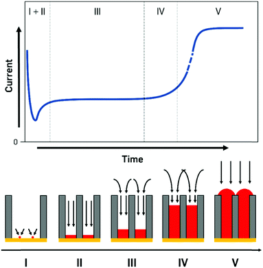
The processes during electrodeposition inside nanochannels are often divided into multiple segments. Even though most literature sources point out different numbers of segments, we will differentiate the nanopore filling process into five regions, based on the governing processes and provide literature examples with their respective interpretations (Fig. 5).
I. Initial seed formation and nucleation.
II. Filling with 1D diffusion layer inside pore.
III. Diffusion layer consisting of cylindrical pore parts and spherical parts over pores. Pores are filled up continuously.
IV. Small contribution of linear diffusion inside pore, large contribution from the overlapping in spherical parts forming a planar diffusion layer outside pores. Pores are nearly completely filled up to the top but not overfilled yet.
V. Pores are filled completely, behaviour of a macroelectrode, overfilling begins, surface is increasing until a continuous layer is deposited.
In the first few milliseconds after the potential is applied to the cathode (zone I), the metal concentration in direct proximity to the electrode is depleted as crystal seeds are formed. In this extremely short time frame, the deposition is largely determined by kinetics as no concentration gradient has been established. As the preparation and design of experiments for this zone can be very challenging due to the small amounts of current and the inhomogeneous nucleation mechanisms, literature sources covering only this region are quite rare.
During this initial stage of electrodeposition, the nucleation process starts on the polarized conductive layer at the bottom of the nanopore. Therefore, the process of applying the conductive layer to the nonconductive AAO membrane influences the nanomaterial growth and can be used to alter the properties of the whole nanostructure.
Fu et al.57 discussed the influence of the conductive film sputtering and seed formation process on the electrodeposition of cobalt, platinum and cobalt-platinum alloys in AAO membranes. One side of a commercial 200 nm pore diameter AAO membrane was sputtered with a gold film to create a conductive base for electrodeposition inside the pores. It was shown that the amount and position of conductive support material influenced the shape and geometry of the deposited nanostructures. By this, mainly two important configurations and mechanisms were pointed out. If a thick gold layer (20 min of Au sputtering) was sputtered onto the AAO membrane, the diameter of the 200 nm wide pore openings was reduced by about 80% and the pores were considered blocked (Fig. 6A). Due to the seed formation and subsequent homogenous growth from bottom to top, the electrodeposition into AAO in the closed configuration resulted in a diffusion-controlled nanowire growth mechanism for all three species (Co, Pt and CoPt), following the scheme in Fig. 5. The diffusion limitation of the growth mechanism was shown by switching from constant-current electroplating to pulsed deposition, where the pulsed technique always resulted in larger growth rates.
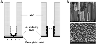 | ||
| Fig. 6 (A) Influence of the contact sputtering process of a blocked and unblocked membrane onto the seed formation and the following electrodeposition of nanomaterials. (B) SEM images of the resulting CoPt nanotubes and nanowires. Reproduced with permission from J. Fu, S. Cherevko and C.-H. Chung, Electrochem. Commun., 2008, 10, 514.57 | ||
When the authors only sputtered a thin conductive film (10 min of sputtering) on the backside of the AAO membrane, the 200 nm wide pore openings were blocked to a lesser extent and the diameter was only decreased by about 50%. Furthermore, some gold was also deposited inside the channels, acting as a conductive coating on the inner walls of the pores (Fig. 6A). For the electrodeposition into this open pore configuration, a slightly different growth mechanism was proposed, as platinum rather starts to nucleate at the small gold particles inside the pores than on the gold layer on the pore bottom. After seed formation, Pt ions are more likely electroplated on the freshly deposited platinum at the pore walls, which lead to the formation of hollow nanotubes instead of dense wires formed at the blocked pores.
For cobalt, it was found that the nanotubes closed and formed wires after relatively short deposition times, which is attributed to a higher cobalt diffusion rate through the AAO channels. Due to diffusion limitation, it was possible to form CoPt alloy nanotubes analogue to the pure platinum growth mechanism. Here, the pH buffer impeded diffusion and, therefore, supported tube formation. A wire like growth of CoPt was, however, observed after several hours of deposition time due to a slow filling/closing of the nanotubes.
With these experiments, it was shown that the initial seed formation process, as well as the properties of the conductive electrode material are heavily influenced by the confined geometry and mass transport inside nanopores.
As the main part of electrodeposition into nanopores is strongly dependent on diffusion under confinement, zones II to IV are of particular interest, which is reflected by a significantly larger number of articles addressing these deposition stages. Due to the large overlap and smooth transition between these zones they will be discussed in a coherent relation.
A qualitative kinetic model for the potentiostatic deposition of copper into ion-track etched polycarbonate membranes was presented by Schuchert et al.58 This nanochannel membrane setup was utilized to study the effect of 1D confinement on mass transport and reaction kinetics using potential step experiments. The used 30 μm thick TEPC membrane showed pore diameters of 400 to 450 nm and a mean interpore distance of 1.4 μm. It should be noted that in contrast to AAO the number of nanopores is significant smaller while the interpore distance is drastically larger which therefore influences the mass transport into the pores.
According to the Cottrell equation
 | (1) |
While zone I was not discussed in more detail because of the complexity of processes, zones II to IV were analysed by the i vs. t−0.5 plot (Fig. 7).
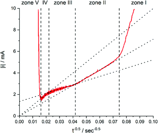 | ||
| Fig. 7 Current of the electrodeposition of copper into 30 μm thick TEPC membranes with 400 to 450 nm nanopores plotted against t−0.5. The electrolyte for the deposition contained 0.25 mol L−1 CuSO4·5H2O and 2 mol L−1 H2SO4. Reproduced with permission from I. U. Schuchert, M. E. T. Molares, D. Dobrev, J. Vetter, R. Neumann and M. Martin, J. Electrochem. Soc., 2003, 150, C189.58 | ||
In zone II, the formed diffusion layer is much smaller than the remaining unfilled pore length. Thus, linear diffusion is rate determining inside the nanochannel. Comparable models for diffusion under these conditions would be those for recessed microelectrodes with a moving electrode/electrolyte boundary.59–61
After a time of around 570 seconds, the diffusion zone reached the pore mouth and started to form a mixed diffusion pattern consisting of a radial part above the pore opening and the linear part inside the pore (zone III, Fig. 5). The authors pointed out that this form of diffusion shows some similarities to the diffusion of recessed microelectrodes at long reaction times, but available expressions from literature59,62 were not sufficient to describe the ongoing processes. From the line fit and its intersection with the y-axis of the i–t−0.5 plot, they concluded that the radial diffusion governs the overall process.
After about 2066 s of deposition, the diffusion zones start to overlap, which results in a quasi-linear diffusion towards the membrane (zone IV). Here, it was demonstrated that the linear diffusion towards the membrane was the rate determining step. The model used to describe the diffusion in this zone is based on an ensemble of microelectrodes in plane with an insulator. By again using the Cottrell eqn (1), it was found that the experimentally obtained diffusion coefficient was equal to the bulk value (Dbulk), obtained in unconfined conditions. This is attributable to the fact that a significant part of the diffusion profile is located outside of the nanochannels.
Kostevšek et al.63 demonstrated the influence of confinement on kinetic parameters during the electrodeposition of metals by comparing the deposition properties on flat substrates with those inside AAO nanochannels. In their study, a flat gold electrode was compared with a gold sputtered AAO membrane (200 nm pore diameter) for the electrodeposition of iron from Fe3+-Cit, palladium from [Pd(NH3)4]2+ and an iron palladium alloy via cyclic voltammetry at scan ranges between 5 and 150 mV s−1. For their experiments the deposition potential was varied between −0.8 and −1.3 V versus an Ag/AgCl (3.5 M) reference electrode. It was possible to extract diffusion- and charge-transfer coefficients (α) using the Randles–Ševčík (2) and Delahay (3) equation64
 | (2) |
 | (3) |
From the plot in Fig. 8A, the diffusion coefficients for Fe3+-Cit and [Pd(NH3)4]2+ on the flat electrode (2.1 × 10⁻⁵ cm2 s−1 and 5.1 × 10⁻⁵ cm2 s−1 respectively) have shown to be larger than the ones of the confined AAO sample (0.7 × 10⁻⁵ cm2 s−1 and 2.7 × 10⁻⁵ cm2 s−1). This decrease by 2–3 times is attributed by the authors and Napolskii et al.65 to the interaction of the diffusing species with the electrical double layer in the nanochannel. The charge transfer coefficient for Fe3+-Cit reduction was determined to be close to 0.5 for the flat and the confined sample (0.46 and 0.63), indicating a symmetric process, while it was slightly more asymmetric for [Pd(NH3)4]2+ reduction, with coefficients of 0.42 and 0.35.
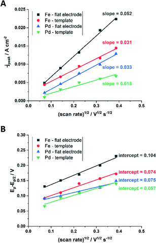 | ||
| Fig. 8 Determination of the diffusion coefficient (A) and the charge transfer coefficient (B) from extracted data of the cyclic voltammograms. Reproduced with permission from N. Kostevšek, K. Ž. Rožman, D. Pečko, B. Pihlar and S. Kobe, Electrochim. Acta, 2014, 125, 320.63 | ||
The authors attributed these observations to the fact that at the experimental pH of 9, deprotonated, negatively charged [AlO]− groups at the membrane walls change the formed electrical double layer with respect to that obtained on flat gold electrodes. Accordingly, a positive shift of the open circuit potential for Pd/[Pd(NH3)4]2+ was observed and attributed to an attractive electrostatic interaction between the positively charged ions and the negatively charged AAO structure. This decreases the effective [Pd(NH3)4]2+ concentration at the nanochannel Au electrode, as compared to the flat Au surface. As the iron-citrate complex is mostly negatively charged, it is less affected by the electrostatic interactions, which leads to only slightly shifted open circuit potentials. Finally, the chemical composition of FePd alloys, deposited in relation to the deposition potential was investigated for the two types of Au electrodes. The authors found no effect of nanochannel confinement on the alloy composition, indicating that the above-mentioned confinement effects had no significant effect on the deposition kinetics during FePd alloy formation. They suggested that the conditions for the alloy deposition differ from the single ion ones and therefore cannot directly be correlated.67
While the authors in this example compared the kinetic and mass transport influence between a confined and a non-confined sample experimentally, theoretical modelling of the kinetic and thermodynamic parameters was used by Bograchev et al.66,68,69 In their theoretical study, a more detailed model for the diffusion dynamics and kinetic parameters was proposed for the electrodeposition of metals into a nanopore. For their numerical simulation, they made use of the diffusion domain approximation, by assuming a uniform distribution of equally sized pores and converted the hexagonal unit cell to a circular one. Since their model involves a continuous pore filling process, where the concentration and deposition current are determined by steady-state diffusion, zones II–IV (see Fig. 5) are covered by this simulation.
In order to find a theoretical solution for the proposed model, the mass transport was separated into an approximated 1D-diffusion inside the pore and the axisymmetric region above the pore mouth. It was assumed that the cation concentration in the pore mouth depends on the averaged flux in the outer diffusion layer.
By using the following equation for mixed kinetics
 | (4) |
 is a pre-exponential factor and η is the overpotential, the current density inside a single pore (jp) can be related to the charge-transfer overpotential. This can be used to develop a model that shows the influence of the cathodic potential, the resistance and the exchange current density to the degree of pore filling and corresponding rate. Furthermore, the authors provide an analytical solution for the pore filling mechanism, which allows multiple theoretical studies of the process.
In this model (Fig. 9B), three values of potential difference (U) have been analysed under various deposition conditions. In Fig. 9B two values for the exchange current density have been compared. In (a) and (b), a low value similar to the one for nickel has been used while in (c) and (d) a high value, corresponding to the one for copper was considered. Additionally, the resistance of the solution has been varied between 0 Ω cm2 for plots (a) and (c) and 2 Ω cm2 for plots (b) and (d). From the evaluation of the quasi-linear relation in plots (a) and (b) it was concluded that for low potentials, the deposition process shows a behaviour similar to a galvanostatic process, while for high potentials the deposition is diffusion limited.
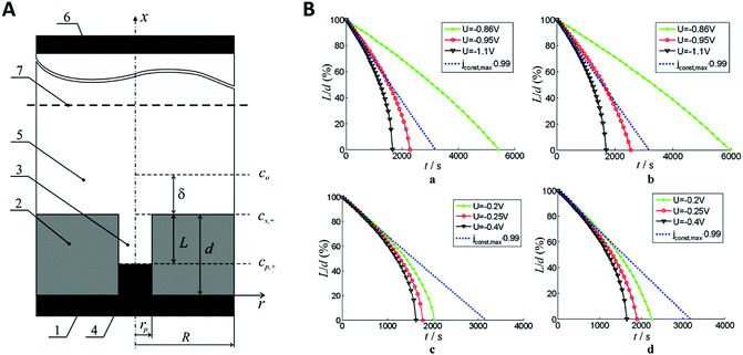 | ||
| Fig. 9 (A) The model used for the simulation shows the metal deposition into a nanopore. Here, rp is the radius of the nanopore, R the radius of the axisymmetric region of the simulation, d the thickness of the membrane, L the length of the empty pore, δ the thickness of the outer diffusion layer, cp,+ the concentration of metal at the pore bottom, cs,+ the concentration of metal at the pore mouth c0 the concentration of metal in the bulk solution, (1) is the metal contact, (2) the oxide template, (3) the empty pore, (4) the deposited metal, (5) the electrolyte, (6) the counter electrode and (7) the plane of the reference electrode. (B) Plots of the simulated unfilled pore length (L) versus the time under various potentials (U). Reproduced with permission from D. A. Bograchev, V. M. Volgin and A. D. Davydov, Electrochim. Acta, 2016, 207, 247.66 | ||
Here, the authors presented a model system for the separate analysis of mass transfer and kinetic parameters of electrodeposition into nanopores. This can be used to calculate a theoretical dataset for comparison with experimentally determined values. While this was set up to further optimize and plan nanomaterial fabrication processes in nanochannels, it may also serve as a suitable tool to determine confinement effects in 1D confined systems.
Finally, when the metal deposition reaches the pore mouth and starts to overfill the pores, caps are formed on the openings and the current response sharply increases as a result of the increased surface area and the purely linear diffusion (zone V, Fig. 5). From this point onwards, the diffusion pattern and processes fully behave like for deposition on a macroscopic, flat surface.
For electrodeposition, a variety of different growth models exists, therefore we will focus on the growth mechanisms of electrochemical nanowire fabrication with respect to kinetics and thermodynamics as discussed in the articles of Zhang et al.,70,71 Shin et al.72 and Dou et al.73 Several different growth modes, including the plane growth, tilted growth and curved plane growth were identified under varying conditions. While it is well accepted that the specific growth mode is dependent on a wide set of parameters, it can be generally described by an interplay of growth kinetics and thermodynamics. The crystal growth rate is governed by either the 2D nucleation rate or the thermodynamic layer growth rate, while the deposition process is mostly limited by kinetics.74 Therefore, by varying the deposition potential, the limiting factors can be shifted to one side of the equilibrium between those two processes. This approach can be used to explain the formation of nanowires and nanotubes. It should be noted that crystallographic properties are also a crucial factor, as the different crystal lattices and planes strongly influenced the preferred growth mode and can change the deposition process regardless of kinetic or thermodynamic limitation. In the following, the growth mechanisms for the examples of zinc, cobalt and nickel are demonstrated in dependence of the deposition potential.71
When applying higher DC potentials (here, −1 V) for the metal ion reduction, a mostly perpendicular crystal growth in a 2D-plane or layer-by-layer growth mode was observed, which is thermodynamically preferred (Fig. 10A). For this study, the AAO pore diameter was 70 nm and the electrodepositions were carried out with DC voltages ranging from −1.0 to −2.5 V versus a saturated calomel electrode for 20 min.
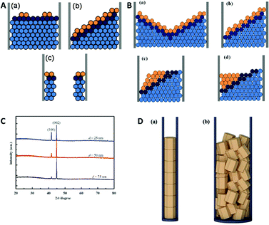 | ||
| Fig. 10 (A) Comparison between the different growth modes inside of nanochannels with orange particles representing the nucleus centre of the growth and dark cyan atoms represent the growth front. (a) 2D planar growth (b) 2D tilted plane growth mode and (c) nanotube growth. Reproduced with permission from H. Zhang, X. Zhang, J. Zhang, Z. Li, H. Sun, J. Electrochem. Soc., 2013, 160, D41–D45.71 (B) (a) shallow pan growth mode, (b) tilted plane growth at the cathodic half-cycle. (c) and (d) rearrangement of the nascent atoms during the anodic half-cycle. (C) XRD pattern of Co nanowires at different pore diameters. (D) Schematic representation of the deposited grains inside AAO nanochannels where (a) the pore diameter is approximately the same as the grain size and (b) the pore diameter is significantly larger than the grain size. Reproduced with permission from H. Zhang, W. Jia, H. Sun, L. Guo and J. Sun, J. Magn. Magn. Mater., 2018, 468, 188.70 | ||
Hereby, nanowires with a 2D-layered structure are formed. At lower overpotentials (−1.25 V), an intermediate state was observed where thermodynamics and kinetics both control the deposition, which resulted in 2D-tilted plane growth modes (Fig. 10A). With further decreasing potentials (−2.5 V), kinetics become the dominant influence and the in-axis growth rate was observed to be higher than the layer growth rate perpendicular to the pore. This constellation has been observed to result in the formation of nanotubes (Fig. 10A).
In further investigations by Zhang et al., more detailed insights into the actual deposition process during an electrodeposition of nanowires was demonstrated.70 Therefore, 20–100 nm AAO membranes were used for the alternating-current (AC) electrodeposition of cobalt from a solution containing 0.1 M CoSO4·7H2O and 0.1 M H3BO3 at AC-potentials of 10, 15 and 20 V. The ongoing processes during single AC half-cycles could be identified and shown in this example. In contrast to the before discussed DC deposition techniques, the potential needed for the kinetically controlled nanowire deposition is at around 10 V or higher in AC deposition. Here, one potential cycle can be split into an anodic and a cathodic half-cycle during which different electrochemical reactions occur. The authors assumed that the nanowire growth in the 2D tilted plane mode takes place during the cathodic half cycle and the tip of the nanowire grows in shape of a “shallow pan” (Fig. 10B).
After the potential is inverted for the second (the anodic) half-cycle, the nascent atoms in the topmost layers of the nanowire rearrange to thermodynamically stable crystallographic conformations as the atoms at the tip of the nanowire have sufficient time and energy to relocate to the thermodynamically favourable flat surface. To verify this growth model experimentally, Co nanowires were AC deposited at 20 V in three different pore diameters and subsequently analysed by X-ray diffraction (XRD). The XRD measurements (Fig. 10C) show two peaks representing the kinetically favoured crystallographic plane (100) and the thermodynamic (002) plane. From this data it can be assumed that these Co nanowires preferable grow along the thermodynamically favourable (002) plane, which is in good agreement with the proposed model. For smaller pore sizes the XRD peak of the (100) plane gets significantly stronger which is explained by the authors to be linked to the orientation of the deposited grains along the pore axis (Fig. 10D). If the pore diameter is in the order of the grain size the grains will be stacked along the axis on top of each other resulting in an increase in the (100) peak. With increasing pore diameter, the crystal grains are deposited in a more unordered fashion, resulting in a smaller (100) peak.
A similar but slightly more complex study of electrodeposition of Bi/BiSb multilayer nanowires was performed by Dou et al.73 In their experiments a charge-controlled pulse deposition technique was used for the formation of thin Bi/Bi0.5Sb0.5 multilayer nanowires from an aqueous solution of their chloride salts into a 60 nm pore diameter AAO membrane.
Bi/BiSb nanowires have been electrodeposited in a two-electrode pulse plating setup by applying 11.5 and −2.0 V in pulses of 8 ms and an off-time of 12 ms between them.
For these deposition conditions, a highly ordered bilayer structure was observed with equally distributed and reproducible thicknesses of the different layers. The deposited layers show a strictly normal orientation to the nanowire axis, which was interpreted as the confined equivalent of a layer-by-layer bulk deposition (Fig. 11A). The deposition process has been considered as thermodynamically equilibrated and therefore happening via the thermodynamically favoured growth mode. Selected area electron diffraction (SAED) analysis of the sample verified the single crystalline structure of the deposits. Under same experimental conditions also a second growth mode has been observed for the first time, which was not observed for the single element or alloy deposition: step growth or tilted growth mechanism (Fig. 11B). In this case, the deposition process was controlled by kinetics and the deposited ions had enough energy to diffuse to the step edge. Here, the deposition rate is relatively high, while ion diffusion on the surface is relatively low. A transition between the two growth modes has been observed (Fig. 11C) for specific conditions, like temperature or ion concentration changes, which caused a transition from the tilted plane growth to a layer-by-layer growth mode. In the transient zone, several layers of deposited material showed an intermediate structure between the two modes. The authors hypothesise that a fluctuation in the thermal conditions provided sufficient energy to the ions (red in Fig. 11C) to overcome the energetic diffusion barrier at the edge of the crystal plane (Ehrlich–Schwoebel barrier), which enables Frank–Van der Merwe growth and is explained elsewhere in more detail.75,76 In this theory of local fluctuations of ion concentrations, it is assumed that the reduced ions have enough time to relax to a more stable state before the deposition of the next ions occurs. Thus, it is assumed that also the transition from layered growth to tilted growth is possible under comparable conditions. Furthermore, a kinetically controlled bowl-like growth has been observed, which was identified as a stable layer-by-layer growth, once the bowl shape had evolved (Fig. 11D). Based on the work of Wang et al.78 and Valizadeh et al.,79 it was assumed that the bowl-shape is attributed to the electrode contact material, which entered the pores and adhered on the nanochannel walls during sputtering.
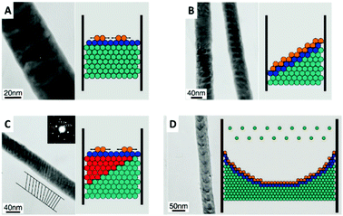 | ||
| Fig. 11 TEM image and schematic representation of (A) 2D plane growth mechanism with arrows representing extending of nucleus in the plane. (B) Tilted plane with layer by layer growth. (C) Transition from tilted plane growth to plane growth with red atoms representing atoms that jumped the Ehrlich–Schwoebel barrier. (D) Bowl like growth mode. Reproduced with permission from X. Dou, G. Li and H. Lei, Nano Lett., 2008, 8, 1286.73 | ||
A completely different growth mechanism was proposed for an electroless deposition process into nanochannels by Ji et al.77 Here, the growth of Cu nanowires was divided into two reactive steps. First, the seed formation or nucleation process which follows the bulk reaction pathway, subsequently followed by a new growth mechanism which explains the continuous growth even in a confined nanochannel setup (Fig. 12).
The formation of CuTCNQ (TCNQ: 7,7,8,8-tetracyanoquinodimethane) nanowires in AAO membranes of 40 μm length with 200 nm pores, based on macroscopic ion transfer through the nanowires was investigated. In their experiment, a conductive copper film was evaporated on one side of an AAO membrane, which was subsequently sealed from the outside with a protective and inert PTFE film so that a reactive interface is only present inside the nanochannels. The sample was immersed into TCNQ containing solution, which leads to a chemical reaction forming CuTCNQ inside the nanochannels at the interface to the Cu working electrode. It was observed that the Cu surface reaction was preferred over the bulk reaction in the confined nanochannel environment and therefore, fully covered by CuTCNQ crystals. A continuous deposition of CuTCNQ was also observed in a later stage of the nanochannel filling process. Because it is unlikely that the relatively large TCNQ molecules diffuse through the length of the already deposited material to react with the Cu electrode, a new mechanism based on ionic transport was proposed. According to the established mechanism by Duan et al.,80 TCNQ is adsorbed and reacts on the Cu surface in stage I and II (nucleation). At the point of a full CuTCNQ surface coverage, TCNQ molecules can only adsorb on the top of the nanowire which leads to a continuous layer-by-layer growth. In this model, the difference in redox potential between Cu and TCNQ generates an electron conduction from the Cu at the base through the nanowire to the adsorbed TCNQ molecules at the top. Since the chemical potential of copper at the bottom of the nanowire is significantly larger than on the top, Cu+ ions are expected to migrate through the nanowire to the top where they react with the adsorbed molecules to form CuTCNQ. The authors suggest that this novel growth mechanism is observable only in confined experimental setups, while the traditional direct reaction mechanism is dominant in open systems where bulk reaction occurs.
2.3. Geometric confinement
The likely most intuitive effect of nanochannel confinement is the geometric aspect. Here, the spatial characteristics of the nanochannel are used to alter the shape of a material, which gains special properties that would be much harder or impossible to achieve with conventional production techniques, such as mechanical modification. Additionally, some effects or properties differ from bulk or flat surfaces, when subjected to nanochannel confinement. Only a few examples for this will be provided here, as the underlying principle is rather simple, although the experimental setup and parameter selection is not in most cases.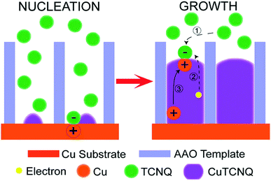 | ||
| Fig. 12 CuTCNQ nanowire formation with ion transfer mechanism. Reproduced with permission from H.-X. Ji, J.-S. Hu, Y.-G. Guo, W.-G. Song and L.-J. Wan, Adv. Mater., 2008, 20, 4879.77 | ||
Spatial confinement can be used to generate a variety of shape and size modulated products, based on rigid templates. These templates can be modulated by carefully controlling critical reaction parameters, like anodization parameters, temperature or electrolyte composition during the AAO anodization, which alters the shape in multiple ways. Additionally, by using pre-patterning techniques, the relative position between the self-assembled nanochannels can be influenced. These custom shaped and orientated nanochannels can be used to deposit nanowires, which represent the negative of the AAO shape.81 Exemplary, some possible nanochannel geometries and arrangements are shown in Fig. 13.
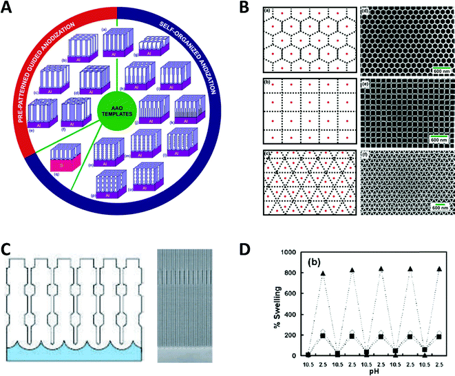 | ||
| Fig. 13 (A) Schematic overview of documented nanochannel geometries grouped by their type of formation. (B) Cell representations and SEM images of prepatterned AAO in three exemplary geometries. Reproduced with permission from G. D. Sulka, A. Brzózka, L. Zaraska, E. Wierzbicka and A. Brudzisz in Submicron Porous Materials (ed. P. Bettotti), Springer International Publishing, Cham, 2017.83 C Schematic and SEM image of a diameter modulated AAO membrane. Reproduced with permission from W. Lee, R. Ji, U. Gösele and K. Nielsch, Nat. Mater., 2006, 5, 741–747.84 D pH dependent swelling behaviour of PAH/PSS multilayers on flat Si substrate (▲) and inside of 400 nm TEPC membranes (■ and ◊ for different methods of determination). Reproduced with permission from D. Lee, A. J. Nolte, A. L. Kunz, M. F. Rubner and R. E. Cohen, J. Am. Chem. Soc., 2006, 128, 8521.82 | ||
Particularly remarkable in the context of spatial confinement is the deposition of polymers into nanochannels of complex geometries (Fig. 13A–C). By using nanochannels with complex geometries as a mask, the resulting deposits also follow this geometry. Thereby, special confinement allows the easy production of nanomaterials in various shapes and geometries which would be impossible to achieve with traditional fabrication methods.
The behaviour of softer materials, like polymers under nanochannel confinement has also been studied and shows some interesting effects. The geometry effect of nanochannel confinement was shown by Lee et al.,82 who compared the pH induced reversible swelling behaviour of polymer multilayers on a planar surface with that inside nanochannel confinement (Fig. 13D). For the experiments, planar silicon substrates as well as track-etched polycarbonate membranes were modified with poly-(allylamine hydrochloride) and poly(sodium 4-styrenesulfonate) multilayers (PAH/PSS). These multilayers undergo a discontinuous swelling and deswelling cycle when exposed to solutions of varying pH. The reversible swelling and deswelling transition was induced by changes of the PAH amine group ionization which therefore induced a conformational change of the chain. A shift in its pKa value is attributed to the hydrophobic association of free amine groups. When comparing this behaviour on a planar substrate with that inside the nanochannel confinement under identical conditions, a significantly smaller swelling of the polymer resulted inside the confined space. The authors proposed that stress is induced in multilayer nanotubes, which arises due to the volume limitation inside the nanochannels and counteracts the swelling phenomenon. Besides this ability to reduce usually undesired stress in functional polymers, it was shown that a swelling polymer modified membrane can be utilized as a pH sensitive gate/valve as it can reversible open and close the nanochannels.
The spatial confinement of rigid membranes can also be used as nanoreactors, exhibiting different properties compared to the bulk reaction. In a study by Giussi et al.,85 the radical polymerization kinetics and confinement effects of styrene inside a 35 nm pore size AAO membrane have been investigated and compared to bulk polymerization. The reaction inside the nanochannels was performed by introduction of monomer into the nanochannels and thermal polymerization under nitrogen atmosphere. The same procedure without the AAO membrane was performed for the bulk reaction.
The characterization of both obtained polymers showed several differences in the polystyrene properties, which were attributed to the nanoreactor confinement. While molecular weight and polydispersity index of both polystyrene samples were similar at low conversion (up to 50%), significantly smaller values were achieved in the nanoreactor with increasing conversion (>65%). The authors ascribed this behaviour to the enhanced thermal control inside the nanoreactor, due to the smaller reaction and heat transfer volume. They additionally demonstrated that the nanoreactor-derived polystyrene sample shows a higher thermal stability, which was attributed to a higher syndiotactic degree by Chen et al.86 Moreover, a confinement effect on the glass transition temperature and the mobility of polystyrene was observed, which was further discussed by Shin et al.,88 who affiliate this with an influence of the confined reaction to the cooperative movements of the polymer. These examples showcase promising directions for the utilization of confinement to improve the quality of polymer materials, a field that may greatly benefit and grow once the underlying effects and, hence, future development potentials are better understood.
Another application of spatial confinement is demonstrated by Liu et al.87 in their article about stabilization of lithium metal anodes by utilization of nanochannel confinement effects. Since the dendrite formation in lithium containing batteries is a tremendous problem, known to cause device failure, a new approach is presented that uses polyimide nanochannels with high aspect ratios. Therein, dendrite formation is suppressed by levelling the deposition through nanoconfinement between multiple nanochannels. By using numerical simulations, the Li+ flux on a non-confined electrode (Fig. 14A c) was shown to be drastically enhanced around the non-uniformly deposited lithium nuclei, which led to the typically observed formation of dendrites. This beneficial influence of the nanochannels can be rationalized via simulations of the associated mass transport of Li+ to the electrode. The derived contour plot (Fig. 14A d) shows a homogeneously distributed ion flux in all nanochannels, which indicates a uniform growth without the formation of dendrite structures. The simulated results support the experimental observations, shown in the SEM images (Fig. 14B). Here, the deposition of lithium on a non-confined electrode at different current densities and deposition capacities (a–c) is compared with the one on an electrode modified with 350 nm polyimide nanochannels (d–l). By numerical simulation and experimental testing, it was shown that the spatial confinement resulted in a uniform nucleation and deposition, based on a more equally distributed Li+ flux inside the nanochannels which therefore could prevent critical dendrite formation processes.
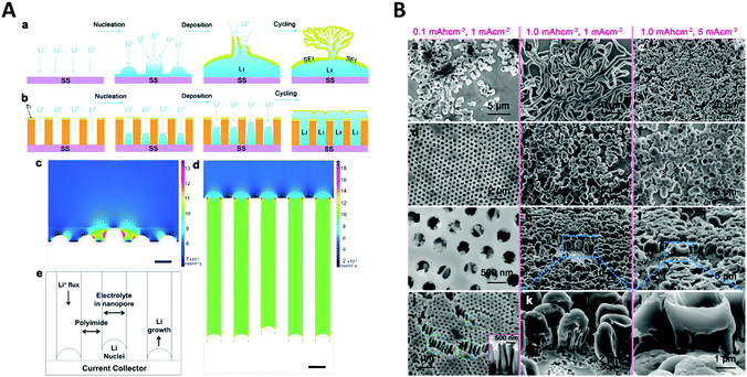 | ||
| Fig. 14 A Schematic comparison of lithium deposition and the associated dendrite formation on a flat substrate (a) compared to a nanochannel (b). Simulations showing the local ion flux during the deposition on a flat substrate (c) and inside a nanochannel electrode (d). (e) Representation of the cell geometry used for the nanochannel simulation. (B) SEM image of the lithium deposition at different current densities and deposition capacities on a flat electrode (a–c) and on a nanochannel modified electrode (d–l). Reproduced with permission from W. Liu, D. Lin, A. Pei and Y. Cui, J. Am. Chem. Soc., 2016, 138, 15443.87 | ||
Thus far, this part was focused on nanochannel confinement for templated electrodeposition with applications for use in electrocatalysis. In addition to that, nanochannel confinement allows for a multitude of unique features, which can be employed for electrochemical sensing, which will be explored in the next section.
3. 1D and 2D confinement in electrochemical sensing
3.1. Types of confining geometry
A significant number of experiments in modern electrochemistry is conducted in the presence of rigid structures, applying geometric confinement onto the system. Such structures can modify the electrode, separate electrochemical cells into compartments or confine whole electrochemical cells. Rigid confining geometries are found in a range of important applications, such as the separation of electrochemical half cells in industry via ion filtering membranes, which are used for example in drinking water treatment or in fuel cells. The application of confined electrochemical cells is mostly relevant in research and includes, e.g. thin layer cells for investigations of unstable electrochemical species, ultra-fast reaction kinetics, local electrochemistry or for coupling with different spectroscopic techniques. Electrode modification by confining structures, in contrast, is relevant in a variety of applications, ranging from porous electrodes utilized to characterize and enhance electrocatalytic effects at newly developed catalyst materials all the way to the industrial application of sacrificial electrodes in batteries and of templates for nano structuring via electrodeposition in nanochannels.17Since electrochemically active species are transported from an unconfined bulk to the electrode, these structural confinements are either considered one- or two-dimensional. Due to the high variety of different systems, we separate them into four main groups, according to the position of the electrodes with regard to the confining geometry and the appearing confinement effects:
3.2. Signal enhancement due to target species regeneration
An obvious effect that a confining system can impose on the electrochemical behaviour of a target species is created by a decreased distance between the two half cells. In an unconfined system, the two electrochemical half cells are embodied by the working and counter electrodes, both separated by millimetres, up to several centimetres.94 These distances are several orders of magnitude larger than the concentration gradients, which are created by the conversion of redox-active species on both electrodes.95 Thus, both half-cell reactions can be considered separately and do not interfere with each other. In such systems, the faradaic limiting current is determined by the mass transport of redox-active species from the bulk to the electrode. The diffusional flux is dependent on electrode geometry, diffusion coefficients and the timescale of the experiment. An in-depth discussion of these effects is beyond the scope of this review and can be found in several elaborate reviews and books about this topic.96,97 Reducing the distance between the electrochemical half-cells to a value, which is smaller than the diffusion layer thickness, leads to a mass transport related coupling of both half cells. Within this distance, electrochemically generated species at one electrode can diffuse to another one, which can be held at a different potential. This way, the species of interest can be generated at one and then measured and regenerated at another electrode. This principle has been exploited in so-called generator-collector experiments for more than 60 years, by using convection as the predominant form of mass transport in rotating ring disk electrodes (RRDE). Electrochemical species are generated at the central disk electrode and subsequently collected at the concentric outer ring electrode, which allows to investigate reaction selectivity, lifetime of intermediates, volatile products, etc. For thin-layer and nanogap electrodes, the electrode distance can become so small, that the collection efficiency approaches 100%, as the majority of the diffusion layer is blocked by the opposing electrode. When sensing an electrochemically reversible redox pair, the target redox-active species can be effectively cycled between both electrodes, enhancing the faradaic response by up to several orders of magnitude. Additionally, the short time that is needed for mass transport between the electrodes (μs range), enables the investigation of quickly degrading products, such as radicals. The collection of the highly unstable oxalate anion radicals (C2O4˙−), formed by electroreduction of oxalate (C2O42−) on a Pt UME by an SECM tip is a suitable example for this, and was observed by Bard and co-workers.93 The authors created a nanogap electrode setup within a TBAPF6 supported N,N-dimethylformamide solution by placing the Pt nanoelectrode that forms the SECM tip at distances between 73 and 500 nm from the Pt UME. By applying potentials of 0.05 V and −1.25 V vs. Pt/PPy- on the tip electrode and the Pt UME (Es), respectively, C2O42− is oxidized on the tip electrode. The generated C2O4˙− radical anions quickly decompose into carbon dioxide and carbon dioxide radicals (CO2˙−) in the solution. Following a slower rate constant, two CO2˙− recombine to C2O42− in the electrolyte. The oxidation of CO2˙− at both electrodes is competing with chemical recombination in the electrolyte and the oxidation of C2O4˙− on the Pt UME (Fig. 16A). With reduced tip/substrate distance (d), the steady state current of the substrate becomes more negative between 500 nm and 140 nm, as the amount of CO2˙− reaching the substrate electrode is increasing. Approaching a distance of 140 nm, the current rapidly increases with decreasing gap distance, as the time needed for inter electrode mass transfer becomes shorter than the decomposition rate of C2O4˙−. This leads to a detectable current associated with C2O4˙− oxidation on the substrate (Fig. 16B). By fitting simulated data at different decomposition rates to the experimentally obtained current–distance curves, the rate constants, radical half-life, and concentration profiles of both radical species were derived with respect to the generator electrode (Fig. 16C and D). Nanogaps created by an SECM system were also used by Sun et al. to enhance the oxygen evolution reaction on a NiO catalyst, utilizing the tip electrode as a collector for the generated oxygen.98 Utilizing fixed nanogap distances, Lemay and co-workers managed to enhance the current response of individual redox molecules in a 40 nm gap by a factor of 104 compared to single molecule conversion at the electrode.99 This enabled the authors to electrochemically detect single molecules and develop an elaborate understanding of diffusion behaviour within nanoconfinement. Within the field of nanoelectrode arrays (NEA) Ma et al.100 and Hüske et al.101 observed current enhancements of more than 15 times, when redox cycling was activated on recessed ring-disk electrodes with an interelectrode distance of around 100 nm for Ru(NH3)63+ and Fc(MeOH)2, respectively. In the above discussed publications we showed, that a lot of limitations, given by the slow process of mass transfer, can be overcome by shrinking the electrode to electrode distance into the nanoscale, for low conductive electrolytes this operation leads to the overlap of the electrical double layers within the cell.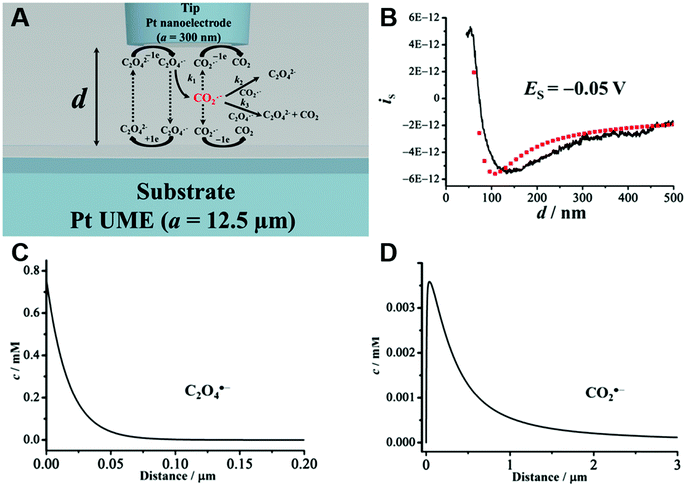 | ||
| Fig. 16 Measurements of the homogenous rate constants of electrogenerated C2O4˙− decomposition in 100 mM N,N-dimethylformamide- via SECM built Pt/Pt nanogap electrode.93 (A) Schematic description of the nanogap setup and the parallel chemical/electrochemical competing reaction steps for a tip generator/substrate collector electrochemical cycling of C2O42−. (B) Measured Steady state current of the substrate electrode in dependence of tip/substrate distance (black curve), applied potentials on the substrate and the tip are 5 mV and −1.25 V vs. Pt/PPy, respectively. Simulated approach curve with chemical rate constants of k1 = 0.55 × 10⁶ s−1 and k3 = 1.5 × 10¹¹ M−1 s−1 for C2O4˙− decomposition (red dotted line). (C) Simulated concentration profiles of C2O4˙− and (D) CO2˙− as function of distance to the generator electrode at steady state and under diffusion limited regime. Reproduced with permission from T. Kai, M. Zhou, S. Johnson, H. S. Ahn and A. J. Bard, J. Am. Chem. Soc., 2018, 140, 16178.93 | ||
3.3. Electrical double layer overlapping
The electrical double layer (EDL) of an interface in an electrolyte solution is dependent on the surface charge of the non-electrolyte phase and the ionic strength of the electrolyte phase. Indicated by the Debye length, the EDL95,102 can protrude less than 1 nm at high electrolyte concentrations (1 M KCl) up to micrometres in unsupported solvents (ultrapure water and inert atmosphere). Since electrode-to-electrode distance in nanoconfined systems is often in a similar magnitude or even smaller than the Debye length of the respective electrode, these systems are called sub-Debye length cells. The resulting overlapping of the participating EDL leads to ion migration and accumulation effects, which influence mass transport within the confined region and electrode kinetics at the EDL. | (5) |
The first term on the right side of eqn (5) describes mass transport by diffusion, the second by migration and the third by convection. The variables Di, Ci, zi represent the diffusion coefficient, concentration, and charge of species i respectively, ∇Ci and ∇ϕ symbolize a concentration and electric field gradient over all three spatial dimensions respectively, ν is the velocity of the surrounding fluid.
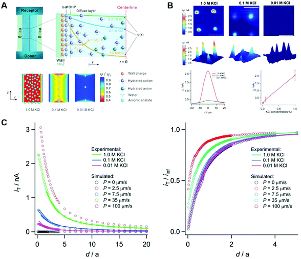
Steeper concentration gradients established at the confining walls lead to an increased diffusional driving force, which opposes the reduced diffusion coefficient of the target species in a confined system. The reduced diffusion in parallel to solid surfaces is imposed by shear forces and temporary surface adsorption and is well defined in literature for electrochemical systems103 or other experimental setups utilizing thin film cells, like liquid cell transmission electron microscopy.104 These shear forces increase with the capacity of the EDL as shown by Saha et al. in ion pump experiments.105 If both walls of a nanochannel bear a similar surface charge and wall-to-wall distances are smaller than the Debye length of both respective surfaces, surface charge cannot be compensated across the channel, leading to an ion current rectification (ICR) effect for bulk ions with the same charge sign as the wall material. ICR is defined as asymmetric electrochemical current–voltage dependencies, caused by a charge selective asymmetry in the potential-dependent ion flux through confining geometry. The intensity of ICR is measured by the rectification ratio, which is directly proportional to the asymmetry of mass transport for the participating ions within the confined area.106 A completely blocked mass transport of negatively charged species, through silica nanochannels, due to ion rectification at low electrolyte concentrations was shown for Ru(CN)64−(aq) by Yao et al.107 Utilizing the collection mode of a Pt tip SECM setup in a aqueous KCl solution, the authors showed that the anion permeability in ultrathin silica nanochannel membranes (SNM) with a pore diameter of 2.3 nm exhibits a strong dependency on the KCl concentration. The tip was immersed into an electrolyte solution and the potential was set to 0.9 V vs. Ag/AgCl. A second liquid pool containing a 5 mM solution of K4Ru(CN)6 dissolved in the same electrolyte was separated from the collector electrode by a SiN chip. The used chip possessed a perforated window with micrometre-sized openings, while its electrode terminated surface was fully covered by the SNM. To observe a faradaic current signal, the Ru(CN)64− anions must pass the nanometre scale pores within the separating membrane and reach the electron transfer plane of the tip electrode. Due to the negative surface charge of the silica walls, an overlapping EDL forms across the nanochannel, leading to a system where the effective potential at any position between both walls is ruled by the Debye length (Fig. 17A).
 | ||
| Fig. 17 Measurements of the EDL dependent Ru(CN)64− ion rectification and permeability within 3 nm silica nanochannels at different concentration of aqueous solution measured via SECM.107 The Pt tip collector electrode, Pt wire counter electrode and Ag/AgCl reference electrode are placed in a Ru(CN)64− free solution separated from 5 mM K4Ru(CN)6 in the same amount of electrolyte by 150 nm thick SNM membrane. (A) Schematic description of the double layer formation in sub 3 nm silica channels at KCl concentrations of 0.01, 0.1 and 1.0 M (top), and simulated propagation of the electric field through the channel at the examined concentrations (bottom). (B) SECM mapping of the membrane surface at different electrolyte concentrations. (C) Experimentally obtained and simulated limiting current (total = left, normalised for bulk current = right) as function of the electrode-membrane separation for different KCl concentrations (experimental) and simulated permittivity factors P. Reproduced with permission from L. Yao, F. P. Filice, Q. Yang, Z. Ding and B. Su, Anal. Chem., 2019, 91, 1548.107 | ||
At high KCl concentrations, the EDL exhibits a thickness of around 0.3 nm, leading to a rapid decay of the electric field around the walls of the nanochannel. At decreasing electrolyte concentrations, the ionic strength in the channel is reduced, causing the formation of a negative electric field across the whole nanogap diameter, repelling negatively charged Ru(CN)64− ions, reducing the effective diameter for diffusion. The microscopic nature of the SECM systems allows to differentiate permeable regions on the SNM surface given by the 18 μm windows in the underlaying SiN support. Scanning over the window positions results in a detectable current answer for a solution supported by 1.0 M KCl, peaking above the window centre. This effect is strongly reduced for lower KCl concentrations (Fig. 17B). Numerical simulations of the electrochemical cell allowed to quantify the rectification, as the acquired approach curves fit well to simulated collection curves at different membrane permeabilities (P), which were used to describe the diffusional mass transfer through the membrane (Fig. 17C) according to
| D[∇cd]z=0 = D[∇cr]z=0 = P[∇cd(x,y,0) – cr(x,y,0)] | (6) |
EDL overlapping dependent ion gating was realized in conical nanochannels, as the channel walls were polarized by an external potential. This allowed them to adjust the ion distribution in the nanochannels and thus, to control the extend of ion rectification.110 Mao and co-workers created ion rectification in a nanopipette system by decorating the pipette walls with polyimidazolium brushes.111 Having presented showcases for a confining geometry leading to an asymmetric ion mobility for sub-Debye wall-to-wall distances and equally charged walls, we will discuss how EDL overlap effects caused by such geometries can influence the reaction kinetics of non-adsorbing redox-active species.
 | (7) |
In (eqn (7)), ia0 and it0 are the apparent and “true” exchange current density, respectively, β is the transfer coefficient as described by the Butler Volmer (BV) formalism and ϕ2 is the potential at the plane of electron transfer (PET). Ion accumulation across the OHP leads to a change in reorganization energy for solvent and/or ligand shells after electron transfer, according to the Marcus–Hush–Chidsey (MHC) model. For systems with low conductivity and high overpotentials, this reorganization becomes the rate determining step. In such systems the MHC model deviates from the regular BV model.96 Such non-BV systems are strongly influenced by the change in OHP composition due to EDL overlapping. Being combined, the Frumkin effect and the solvent reorientation can lead to strongly altered electron transfer kinetics within the confinement of sub-Debye length nanogaps. White and co-workers115 reported a field assisted current increase during the redox-cycling of Ru(NH3)63+/2+ with decreasing solvent conductivity in 147 nm nanogaps. The authors utilized a circular Pt/Pt nanogap electrode, fabricated by the nanogap cell method, first reported by Zevenbergen et al.,116 where nanometre thin Pt layers are separated by a sacrificial Cr layer and subsequently passivated by a sputtered SiO2 layer. Chemical etching of the Cr layer creates a cavity between both Pt layers, dependent on the previous height of the Cr layer (150–450 nm). The used circular SiO2 structure is than covered with a droplet of aqueous solution, diffusing through a drilled hole into the nanogap. The usage of such a macroscopic droplet allows the application of a commercial Ag/AgCl reference electrode (Fig. 18A). The thickness of such, so called ultra-thin layer electrodes can be derived from its limiting current Ilim, the overlap area of both electrodes A, the bulk concentration c and diffusion coefficient D of the species i.
 | (8) |
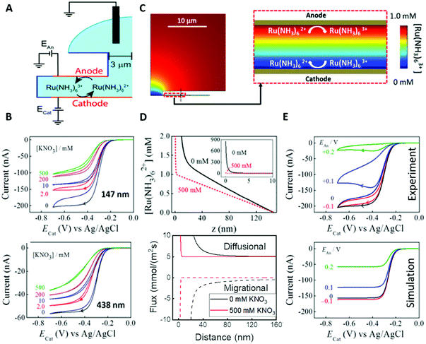 | ||
| Fig. 18 Enhancement of the Ru(NH3)63+/2+ redox process due to overlapping double layer effects in a nanogap electrode. (A) Schematic description of the electrochemical cell. Pt microelectrodes form anode and cathode, aqueous solution of Ru(NH3)6Cl3 in varying concentrations of KNO3 form a droplet on the thinlayer cell. (B) Obtained CVs at different KNO3 concentrations for 147 nm (top) and 438 nm (bottom) wall to wall distance. (C) Simulated cell geometry and concentration mapping of Ru(NH3)63+ concentrations within the electrochemical cell. (D) Simulated Ru(NH3)62+ concentrations (top) and ionic fluxes (bottom) at 0 and 500 mM KNO3, respectively (z = 0 marks the cathode). (E) Experimental (top) and simulated (bottom) CVs for the unsupported Ru(NH3)63+/2+ couple within a 147 nm gap, under varying anode potentials. Reproduced with permission from Q. Chen, K. McKelvey, M. A. Edwards and H. S. White, J. Phys. Chem. C, 2016, 120, 17251.115 | ||
By utilizing an aqueous solution of 2.6 mM Ru(NH3)6Cl3 the authors showed an enhancement for the current response of the Ru(NH3)63+/2+ redox pair in sub 500 nm nanogap electrodes with decreasing concentration of KNO3 as supporting electrolyte (Fig. 18B), this effect is more pronounced for smaller gap widths. The experimental conditions of the nanogap, with a Pt anode held at 0.0 V vs. Ag/AgCl and a Pt cathode cycled from 0 to −0.7 V were numerically simulated to track concentration profiles and mass transport of the Ru(NH3)63+/2+ pair (Fig. 18C). In good agreement with the experimental data, a migrational flux of Ru(NH3)63+/2+ towards the cathode was predicted, leading to an ion enrichment at its OHP (Fig. 18D). The observed electric field, governing the migrational flux, reached values of −33 mV at the OHP and decayed to 0 mV within the first 2 nm for the highly supported solution, while a less steep potential decay led to a potential of −86 mV at the OHP and a nonzero negative potential over the whole gap width for the unsupported solution. Despite the high difference in potential drop across the OHP, for both cases the authors identified the migrational supported regeneration and enrichment of Ru(NH3)63+ on the cathode as the main reason for the enhancement. This is due to the already fast kinetics of the redox couple under investigation and the rather slow scan rates. By applying a positive bias on the Pt anode the beneficial effect of migration was reversed as its positive surface charge repelled Ru(NH3)63+ ions, leading to a reduced regeneration efficiency (Fig. 18E). The deviations in limiting current and hysteresis between the experimental data and simulations were credited towards reactant adsorption. Electrochemical noise created by such adsorption effects within nanogap electrodes were investigated by Kätelhöhn et al.117,118
In their previous work, White and co-workers reported activity dampening of the oxidation of FcTMA+ within a similar electrochemical cell at low electrolyte concentrations.108 These findings strongly agree with the aforementioned enhancement due to the formation of an electric field across the nanogap, as the positively charged working electrode repels the FcTMA+/2+ couple. Concluding their work, the authors suggest an enhancement effect for redox couples with a formal potential E0 below the potential of zero charge (PZC) of the used electrodes and a dampening effect for couples with E0 above the PZC.
Kwon et al. reported a ca. 250-fold current enhancement at a rectification ratio of about six for the Fe(CN)63/4− couple in an unsupported aqueous solution, confined in a nanogap-like nanopore system.119,120 Utilizing the ability of SECM to form Nanogaps of variable distances, Mirkin and co-workers showed that a detectable enhancement in electron transfer kinetics can also occur in well-supported solutions.121 In a 1.0 M aqueous KCl solution, they observed increasing electron transfer kinetics with decreasing gap size for the Fe(CN)63/4− redox couple. The above discussed effects of nanoconfinement on the electrical double layer only considered effects caused by ion accumulation and migration. While the established Gouy–Chapmann–Stern (GCS) model of the EDL is currently revisited for regular electrochemical systems, for electrochemistry under confinement significant deviations from the GCS model have clearly been shown.122,123 By analogy to the solvated ions, the molecular dipoles can orient along the electric field,124 leading to local changes in polarity and thus in free energy of solvation or adsorption. Especially the effect of the latter impede the predictability of the EDL structures under biased potentials as shown by Alfrano et al.125 Unusual alignment of single molecules and formations of ice-like networks from solvent molecules126 under confinement might facilitate these deviations even further and will be introduced in the next section.
3.4. Sub-nm effects in electrochemical confinement
As distances between confining structures get smaller and eventually reach single digit nanometre separation, short-range interactions might influence the measured electrochemical signal. These short-range interactions arise from the molecular dynamics of the confined system and are only briefly discussed in this review, as their investigation is mainly conducted via ab initio simulations, which are complicated to simulate under electrochemical conditions as discussed in the introduction (Section 1.4). Structures separated by single digit nanometre lengths are hardly realized and often degrade under experimental conditions, although recent developments in nanogap technology and electrochemical sensitivity might change this.16,131–133 One effect that may arise due to this confinement is the influence of specifically adsorbed molecules on the OHP and ion mobility. Zhao et al. used a polyelectrolyte covered nanopore to effectively gate ionic permeability by pH adjustment.127 They measured the ionic current of solvated NaCl flowing through the polyelectrolyte decorated nanopore orifice at different pH values. Due to the high electric field imposed by the polyethylenimine, no ion flow is observed at high pH values. Below pH 4, the polyelectrolyte charge is balanced by H+, leading to a polymer swelling, and thus distribution of the charge within the nanopore orifice. The charge distribution strongly reduces the electric field and permits ion flow (Fig. 19A). A similar effect of surface immobilized species on ion transport was found by Wang and co-workers, as they utilized metal organic framework sub-nanochannels as light triggered gating devices.134 Another example for short-range effects is site selective substrate processing in nanoconfinement, which is a fast growing field in organic chemistry, as it can impose regioselectivity. In their recent work, Bayley and co-workers utilized the ionic current through protein based nanopores to investigate the site specific cleavage of a polymer, catalysed by thiol species immobilized on the nanopore walls.128 The ionic current is completely blocked by the polymer in the nanopore (Fig. 19B, right). When the thiol species adsorbed on the nanopore and the disulfide group of the polymer overlap in this configuration, the polymer is cleaved at its disulfide group, reenabling ion transport through the blocked nanopore. In dependence of the thiol position, either the upper peptide part or the lower oligo saccharide part binds to the thiol group, leading to different current responses (Fig. 19B, left and middle). Moving to smaller confined species, Alexa et al. presented a 2D layer of covalent organic frameworks (COF) on a Au electrode as suitable confinement to beneficially influence HER activity.135 They showed that the polarity of the functional groups within the COF influences water orientation and free energy of adsorption, leading to an energetically more favourable water splitting on the Au electrode for a polymer with a nitrogen to water ratio of 0.5. Under extreme confinement (<1 nm), the available space is not sufficient for full solvation of molecules and ions, which leads to an altered dielectric behaviour, activity and perturbed shear movement of the solvent. Effects like these are mainly investigated in silico and on non-biased systems and are only shortly discussed within this review. Nevertheless, the experimental awareness towards short range confinement effects should be raised, as two-dimensional materials and intercalation processes become more prominent in electrochemistry, such effects may gravely affect electrochemical measurements in the near future.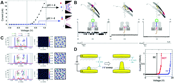 | ||
| Fig. 19 Effects of altered molecular orientation under single digit nanometre confinement on the electrochemical response of the observed system. (A) Utilization of a polyelectrolyte complex adsorbed on the orifice of a glass nanopore for ion gating triggered by pH changes. The swelling behaviour of a zwitter-ionic polyelectrolyte allows the passage of anions through the orifice at high pH. Reproduced with permission from Y. Zhao, J.-M. Janot, E. Balanzat and S. Balme, Langmuir, 2017, 33, 3484.127 (B) Site-selective polymer splitting within a protein nanochannel investigated via ionic current blocking measurements (see Section 3.3.1). The pink circle in the nanopore marks the catalytic site, while the pink circles in the polymers mark the target region for the splitting process. Reproduced with permission from Y. Qing, H. Tamagaki-Asahina, S. A. Ionescu, M. D. Liu and H. Bayley, Nat. Nanotechnol., 2019, 14, 1135.128 (C) Altered structural properties of ionic liquids in a 2 nm wide gap of positive charged surfaces, derived from nonequilibrium molecular dynamics simulations. A total of 5 ionic layers where confined. Dependent on the size and dipole of the anion, the density profile changes to a more crystalline structure. Reproduced with permission from S. Di Lecce, A. A. Kornyshev, M. Urbakh and F. Bresme, ACS Nano, 2020, 14, 13256.129 (D) Single-molecular bridging within a gold nanogap electrode separated by a sub 2 nm, electrically modifiable gap. The gap distance is manipulated by electric migration of surface gold atoms and terminated by a adsorption of BDT on both sides of the gap. Reproduced with permission from Y. Naitoh, Y. Tani, E. Koyama, T. Nakamura, T. Sumiya, T. Ogawa, G. Misawa, H. Shima, K. Sugawara and H. Suga, et al., J. Phys. Chem. C, 2020, 124, 14007.130 | ||
A compelling example is the lateral ordering of an ionic liquid between charged surfaces, which was simulated by Lecce et al.129 The authors simulated the structural properties of different ionic liquids confined in a biased 2 nm gap and its implications for IL lubricity by non-equilibrium molecular dynamics (Fig. 19C). They conclude that bulky ILs form highly ordered crystal-like structures under confinement, which is unintuitively increasing their lubricity.
A final type of confinement effects we want to highlight in this section are those on the confining material itself. A well-known problem for nanogap production is the so called electric migration, where metal atoms of the nanogap electrode migrate in the electric field in line with the flowing current, leading to a merging event of the confining walls.136 Naitoh et al. used electronic migration to form 2 nm gaps between Au electrodes.130 They observed the gap shrinkage by measuring the transferred current between both electrodes as conductivity strongly increases with decreasing electrode distance. 1,4-benzenedithiol (BDT) was used as a spacer to prevent merging of the surfaces (Fig. 19D). At the minimum distance, this leads to a measurable bridging resistance of single BDT, as both thiol ligands are adsorbed to different sides of the nanogap, leading to an electron flow directly through the mesomeric molecule.
In this section we elucidated how confinement can affect the polarity and spatial orientation of single molecules, and thus can change the thermodynamics of an electrochemical system. On the contrary, confinement can also lead to an asymmetric polarity of the participating electrodes and thus to long range mass transport effects in some cell geometries.
3.5. Electroosmosis and long-distance confinement effects
For nanopipettes, the specific geometry of the confining structure leads to a series of long-range effects, which can be utilized for ion gating and nanoparticle electrochemistry. Long and co-workers presented quartz nanocapillaries with a nanoscopic Ag coating as wireless bipolar electrodes.137 Utilizing the strong electric field between a working electrode inside the nanopipette and a counter electrode placed in a 10 mM KCl aqueous bulk solution, a potential gradient is implied to the Ag coating of a 50 nm nanopipette (Fig. 20A). Due to this polarization, the Ag at the orifice works as a cathode, reducing H+ to H2, while the Ag closest to the working electrode oxidizes to Ag+. As the formed H2 builds gas bubbles at the pipette orifice and thus blocks the ionic current collected at the working electrode, the faradaic process can be directly monitored. Utilizing a similar high filed gradient at the orifice of carbon covered nanopipettes, Zhou et al. showed an increased collision rate of nanoparticles during impact experiments, as the particles were trapped within the pipettes.138 The authors trapped single IrOx nanoparticles in a 30 wt% H2O2 filled carbon nanopipette with an orifice diameter of around 200 nm (Fig. 20B). Upon collision with the pipette walls, the nanoparticles catalytically split H2O2, leading to a spike shaped current response in the sub-millisecond timescale. Notably, the impact frequency lies far above the value estimated via Brownian motion for a single entrapped nanoparticle. Lastly, a long-range electroosmotic flow (EOF) was found by Mc Hugh et al., emitted by glass nanopipettes containing a biased electrode.139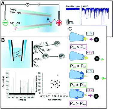 | ||
| Fig. 20 Examples of confinement effects in nanopipette electrodes that induce long range effects, propagating over several μm. (A) The strong electric field near the orifice of a silver coated nanopipette is used to induce a polarity gradient on the silver layer, leading to a utilization of the silver as wireless bipolar electrode, shown by the ionic current blocking experiments, as H2 evolves near the orifice. Reproduced with permission from R. Gao, Y.-L. Ying, Y.-X. Hu, Y.-J. Li and Y.-T. Long, Anal. Chem., 2017, 89, 7382.137 (B) Trapping of a single, catalytically active IrOx nanoparticle in a carbon coated biased nanopipette, leading to peak shaped collision events associated with OER. A long dwell time and increased impact frequency due to the bouncing of the particle from wall to wall was observed. Reproduced with permission from M. Zhou, Y. Yu, K. Hu, H. L. Xin and M. V. Mirkin, Anal. Chem., 2017, 89, 2880.138 (C) Potential dependent electro osmotic flow at a glass nanopipette induced by the ion migration at the wall material. Potential fields propagate across the inner and outer surface of the nanopipette. The direction of electroosmotic flow is influenced by the ratio of the inner and outer field strength. Reproduced with permission from J. Mc Hugh, K. Andresen and U. F. Keyser, Appl. Phys. Lett., 2019, 115, 113702.139 | ||
In an original experimental setup, utilizing a polystyrene bead fixed several micrometres away from the nanopipette by optical tweezers, the authors were able to measure the extent and direction of the emitted EOF. They found that the electric field extends over the outside of the nanopipette and defined the energy, which is required to maintain this field as P, with an outside contribution Pout and an inside contribution Ppore. Dependent on the ratio of inside and outside field strength, the electroosmotic flow can be guided to the pipette's orifice or away from it (Fig. 20C). Remarkably, a direct dependence of this ratio with different used supporting cations was found, exhibiting a high repulsive current for all alkali metal ions at a positively biased electrode, except of Cs, where the current direction is reversed, as Pout increased. Effects like these can be utilized to draw nanoparticles to the electrode, multiply the event frequency of nanoparticle/electrode collision events and enhance the overall performance of single entity impact electrochemistry.
3.6. Conclusion
While the underlying theories behind electron- and mass transfer under sub-Debye conditions were developed more than 50 years ago, experimental access to these domains was obtained rather recently, due to developments in nanofabrication and electronic sensitivity. As it is still highly demanding to fabricate nanostructures and utilize them in experiments, it is still difficult to obtain quantitatively reproducible results. Thus, the full extent of the implications posed by the aforementioned confinement effects onto electrocatalysis, electrosynthesis and electroanalysis is still poorly understood. Nevertheless, the publications discussed in this work already presented a range of beneficial effects such nanoconfined systems exhibit: Nanopores and nanopipettes show an unrivalled sensitivity towards single entities, nanogaps and nanochannels are used for the detection of short-lived products and can be tailored to permit a highly selective increase in current response for the ions under investigation. We expect the implications of double layer effects, such as ion rectification and accumulation to become highly important in electrocatalysis, as it may be used to remove rate limiting products from the electron transfer plane, or to decrease the amount of inhibitor species within the double layer, to name only two examples. Of similar importance is the fast development in the field of sensing via nanoconfined structures, such as the electrochemical detection of single polymer chains with self-assembled nanopores. The utilization of increasingly efficient data processing by machine learning approaches and by tailoring self-assembled structures to quantitatively form arrays of sub-nanometre pores is expected to enable unprecedented sensitivity and resolution. We suggest the investigation of electrolyte effects, such as a cation dependent stabilization of the product as another interesting application of these overlapping double layers. Within fine-tuned systems with high rectification factors, the influence of cation accumulation may lead to altered reaction pathways or transferred chirality, dependent on the type and size of used cations. Especially the ability of sub-Debye length nanogap electrodes to split unsupported water, as shown by Wang et al.,140 is now more up to date than ever, since paragon plants for industrial electrochemical water splitting advance world-wide. While nanopore and nanopipette experiments already exhibit outstanding selectivity and sensitivity, the possibilities for improvement are given by the confining systems, e.g. as ion rectification and electroosmosis can be used to hold the target in place or to increase selectivity. Due to the above-mentioned possible developments and the multitude of benefits already discussed for the single publications, we expect electrochemistry in confined systems to establish as a fast growing, highly important research field over the next years.The fourth and final section of this review will be dedicated to the upcoming field of nanodroplet electrochemistry. In the following section, we want to introduce the term confinement- and elucidate the progression in this field, the techniques to investigate it and why we consider the often long-range effects within nanodroplets as confinement effects.
4. Colloidal single entity confinement
4.1. Introduction
Hereby, the influence of wall interactions is not restricted to certain types, like Van der Waals or other short-range interactions, which are typically used in combination with the term confinement.141,142 Instead, all effects are considered that distinguish a confined species from its bulk counterpart. The systems investigated in this case are clearly differentiated from the aforementioned cases of 1D- and 2D confinement, as the electrode is not part of the investigated systems but is only used to facilitate the measurement. In 0D colloidal confinement, the observed species are completely encapsulated within single entities of a subsystem that is clearly separated from the surrounding fluid.
On the one hand, this definition opens the field of 0D confinement into dimensions that are highly accessible via single entity electrochemical measurements. On the other hand, it restricts the confined system to kinetically or thermodynamically stable entities, which are available by electrochemical means. Cavities consisting of different systems, such as nanocapillaries, self-assembled monolayers and domains of insoluble phases that are forming during an electrochemical reaction are not considered, as one of their boundaries is given by the electrode and is, thus, part of a different subsystem. An immiscible second solvent within a nanocapillary is a special case for 0D confinement, as two dimensions are restricted by the walls of the nanocapillary, while the boundaries of the last dimension consist of the electrode and the liquid/liquid interface between inner and outer solvent. To enable electrochemical characterization, the subsystem needs to be able to move freely within a conductive solvent. The different target systems included in this definition, their respective sizes and typical examples are depicted graphically in Fig. 21.
A less strong form of colloidal confinement can be observed in clathrates and enzymes, where the confined species consist of one target molecule accompanied by smaller solvent molecules. Usually, the number of solvent molecules is too small to form a full solvation shell, since a typical size scale for such cavities lies between 1 to 3 nm. As neither target molecule nor solvent molecules can freely move within the cavity, electric confinement effects are mostly undamped and conformational freedom is reduced.145 This leads to confinement effects related with incomplete solvation, such as changed dissociation rates, altered ion mobility and perturbed solvent dielectric constants. The effects expected for these systems are similar to the sub nanometre confinement effects found in carbon nanotubes or in the nanogap between two graphene sheets, as discussed in Section 3.4. The close-range effects appearing in such geometries are predominantly addressed by means of molecular dynamics and discussed in detail in recent reviews such as the ones by Khlobystov and co-workers146 and Marx and Muñoz–Santiburcio.147
Closed shell soft nanoparticle systems are studied more frequently regarding electrochemistry. Examples ranging from single entity confined colloids over micelles, micro- and nanoemulsions to other liquid/liquid interface-based core shell particles. This group of soft single entities scales from a few nanometre up to several hundreds of nanometres. Fig. 22 depicts the types of nanoscopic droplets that can be investigated by electrochemical measurements.148 A nanometric droplet comprised of a liquid immiscible with the bulk solution and, thus, only protected by the liquid/liquid interface is easily accessible via electrochemistry. These kinetically stabilized systems follow the colloidal behaviour of uncapped nanoparticles and merge with other droplets upon contact. Accordingly, the size distribution of droplets is typically broad and exhibits an evolution to bigger entities over time.149 In contrast to this, the colloidal behaviour of micelles is controlled by their thermodynamics. Micelles consist of amphiphilic molecules with a hydrophobic tail and a hydrophilic head, so called surfactants. Dependent on several factors, like headgroup area to tail length ratio and polarity differences, the curvature and, hence, the micelle size can be varied. For micelles with small curvatures, the surfactant aggregates form a cavity and poorly dissolved molecules with similar polarities to the micelle wall can be encapsulated during micelle formation. Microemulsions are soft particle systems, in which the nanocarriers encapsulate a solvent phase immiscible with the bulk solution and exhibit a surfactant wall. In contrast to nanoemulsions, they are thermodynamically stable.149 By introducing increasing amounts of immiscible liquid into a solution of micelles, the liquid will be distributed within the micelle cavities. This process increases the micelle cavity size and consequently decreases the surfactant curvature. Hence, the micelles grow until the reduction of surface energy, by protection of the liquid/liquid interface with surfactants is in equilibrium with the increase in surface energy due to the decreasing curvature of surfactant wall.150 Up to this point, colloidal behaviour of swollen micelles is thermodynamically driven. Confinement effects on water encapsulated in micellar pockets were first proven by means of infrared spectroscopy by Fayer et al.,151 proving a strongly inhibited relaxation behaviour, when compared to bulk water, in AOT reverse micelles with 1.6 nm diameter.
One special case of microemulsions are trapped droplets, where the micelle cavity contains poorly miscible species of different polarities.152 In such a case, the encapsulated liquid with a polarity similar to the inner micelle wall will form a layered structure within the micelle, creating an additional interface. In contrast to clathrates and supramolecular cages, molecules confined within micelles are not directly constrained by the physical presence of the cavity walls. The electric field within the cavity is strongly damped by the presence of other, freely moving confined species and in most cases, the molecules exhibit a solvation shell. Here, confinement effects usually arise from the ultralow volume within nanodroplets, not from the presence of a confining wall that restricts mass transport and influences the conservation of charge and the presence of multiple liquid/liquid interfaces. As these effects are directly related to the electrochemical behaviour, we will focus on the investigation of corresponding soft nanoparticle systems within the following section.
(I) Transferability; the colloidal system needs to be stable within an ion-conductive phase and maintain its properties during the timeframe of a measurement. This is especially critical as the salts, which are often used as supporting electrolyte, trigger agglomeration processes of protected nano entities as the increased ionic strength in the solution decreases the Debye length.
(II) Measurable faradaic process; the system under investigation must contain an adequate number of molecules that can be electrochemically transformed at the working electrode.
(III) Interaction with the electrode; the droplet must form an interface with the electrode, which allows electrons or ions to enter the cavity and induce the faradaic process of confined molecules. This contact area is strongly influenced by intrinsic system properties, such as wettability of the electrode material, adsorption of surfactant molecules and propagation of the electrical double layer through the droplet.
(IV) Conservation of charge; as the electrode either injects or removes electrons from the confined system, an ionic counter flux must be established that removes excess charges from the system. Such a flux can be formed by parts of the supporting electrolyte entering or leaving the droplet. In the case of a polarity change during the faradaic process, the formed product might leave the droplet to maintain electroneutrality.
4.2. Application
In particular, the work of Dick and co-workers158,163 reveals the outstanding control over nanoparticle size, morphology, roughness and electrode coverage within a water-in-oil emulsion system (Fig. 24C). They prepared aqueous nano droplets, filled with metal precursor salts, such as H2PtCl6, AgNO3, HAuCl4, CuSO4, in a solution of 1,2-dichloroethane and 100 mM tetrabutyl ammonium perchlorate (TBAClO4), by horn sonication. Complementary data from electrochemistry and electron microscopy revealed that the electrode was covered with metal particles ranging from 40 to 1000 nm in diameter. The size of these particles was controlled by the concentration of precursor salt within the droplet. In this way, the authors could generate Pt nanoparticles with a diameter ranging from 40 to 160 nm by varying the concentration of H2PtCl6 within the aqueous phase from 5 mM to up to 100 mM.
| H2PtCl6(aq) + 4e− ⇌ Pt(s) + 6Cl−(aq) + 2H+(aq) − 0.2 V vs. Ag/AgCl | (9) |
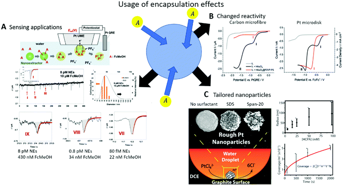 | ||
| Fig. 24 Recent applications of electrochemical transformations conducted on species encapsulated within colloidal single entity confinement: (A) Accumulation of FcMeOH traces from aqueous bulk into organic nanoemulsions and their electrochemical sensing on a Pt UME by single entity electrochemistry (top), different peak sizes associated with the concentration of FcMeOH absorbed into single droplets, while maintaining droplet size (bottom). Reproduced with permission from S. G. Sabaragamuwe, H. Madawala, S. R. Puri and J. Kim, Anal. Chim. Acta, 2020, 1139, 129.156 (B) LSV of colloid HAuCl4 and HAuCl4 confined in polystyrene-vinylpyridine on Pt and carbon micro electrodes conducted in ionic liquid, vs. a Pt quasi reference electrode (QRE) and Ferrocene (Fc)/Fc+ internal standard. Reproduced with permission from M. V. Evers, M. Bernal, B. Roldan Cuenya and K. Tschulik, Angew. Chem., Int. Ed., 2019, 58, 8221.157 (C) Aqueous, microscopic droplets of H2PtCl6 in DCE are reduced on a carbon electrode, to from PtNPs with a high control over NP properties like morphology (left), size (right, top) and surface coverage (right, bottom) by changing the used surfactant, droplet loading and deposition time respectively. Reproduced with permission from M. W. Glasscott, A. D. Pendergast and J. E. Dick, ACS Appl. Nano Mater., 2018, 10, 5702.158 | ||
In addition, a shape governing process was found for the nanoemulsion system, as the deposited Pt nanoparticles exhibited, a spherical shape – unlike their directly deposited counterpart. This effect was proven to be even stronger for protected droplets, as the addition of sodium dodecyl sulfate (SDS) or sorbitan monolaurate (span-20) increased the roughness of formed Pt NPs by about 5%. Following the theory of bulk electrolysis, the content of the droplet is, completely or partially transformed within a split second, depending on the droplet volume and the droplet/electrode contact area.
 | (10) |
Here i0 is the peak current, m is the mass-transfer coefficient [ms−1], Vdrop is the volume of the colliding droplet, A is the contact area between the electrode and the droplet and t is the elapsed time since the initial collision. Thus, varying the deposition time does not influence the size and shape of formed NPs, but only their number, emphasizing the deposition time as tool for coverage control. Following this, the authors could increase the coverage of a highly oriented pyrolytic graphite (HOPG) electrode with Pt NPs from 1 × 10¹¹ to 5 × 10¹¹ for deposition times of 100 and 2000 s, respectively. The obtained data reflect the theoretical coverage behaviour, described by the Cottrell equation, fitted for a colloidal emulsion system.
 | (11) |
Here c and D are the concentration and the diffusion coefficient of the nanodroplets respectively, t is the deposition time and NA the Avogadro constant. The same authors showed, that nanoparticle morphology and porosity can be controlled by varying the viscosity within the droplets.164
In a different approach by Ahn and co-workers, the stoichiometry and composition of precursor salts was varied to yield mixed metal nanoparticles.165,166 A more precise description of metal nanoparticle electrodeposition from aqueous nanoreactors and its benefits can be found in the minireview on this topic devised by Glasscott and Dick.167
| HAuCl4(aq) + 3e− ⇌ Au(s) + H+ + 4Cl− − 1.21 V vs. Fc/Fc+ | (12) |
HAuCl4 was encapsulated within reverse micelles composed of the P2VP-PS and according to spectral analysis, the resulting micelle cavities contained negligible amounts of water.168 Besides the already known effects of a narrow size distribution, which is comparable to the established nucleation method utilizing oxygen plasma,169 and controlled coverage, the electrodeposition reaction exhibited severe differences to blank depositions from bulk solution. To grant electrochemical conductivity, the micelle solution was transferred into the ionic liquid (IL) 1-ethyl-3-methylimidazolium bis(trifluoromethylsulfonyl)imide. A direct reduction of HAuCl4 dissolved within the IL resulted in two distinct reduction peaks at −0.4 and −1.0 V vs. Fc/Fc+, respectively while the encapsulated species exhibited one single reduction peak at −0.7 V.
4.3. Experimental techniques
In this section, we introduce electrochemical methods, mostly based on classic electrochemical experiments, such as chronoamperometry or cyclic voltammetry, frequently used to study colloidal single entity confinement. | (13) |
Here, A is the electrode area, and ν is the scan rate. Due to the limited kinetic information provided by CV measurements, their usability for investigations of ongoing processes within the confined colloid is narrow. Such studies are mainly used to acquire first information about the formal potential of the target faradaic process and the average size of the nano carriers, which can be derived via the Stokes–Einstein equation from Dapp171
 | (14) |
Here rh is the hydrodynamic radius of the colloid and η is the dynamic viscosity of the outer solvent.
More information about the kinetics of nanometric electrochemical systems can be obtained through voltammetric ensemble studies. For ensemble studies, the sensitivity of an electrochemical system is enhanced by simultaneously observing a multitude of target processes at a time, e.g. achieved by immobilizing them at an electrode. This approach is commonly used to investigate electrocatalytic properties of nanoparticles. Here, the working electrode is decorated with a large amount of objects to probe faradaic reactions, like the intensively investigated oxygen evolution reaction (OER), simultaneously occurring on many of those objects. Mass transport limitations can be further reduced by convection; induced by rotating ring disk electrodes (RRDE) or magnetohydrodynamics (MHD). In the early 2000's, Davies et al. applied the principles of ensemble studies on microscopic water droplets, which were immobilized on a graphite electrode immersed into a 200 mM solution of tetrabutylammonium phosphate in 1,2-dichloroethane (TBAP/DCE) (Fig. 25A).172 The reversible transformation of ruthenium hexamine (Ru(NH3)62+) was used to probe the mass transport at the liquid/liquid interface. By observing the peak separation for varying concentrations of TBAP in the bulk phase, the authors demonstrated that electroneutrality within the aqueous droplet was maintained by ion transfer through the DCE/water interface. They identified a TBA+ insertion into the droplet as the rate determining step for the ongoing faradaic process (Fig. 25B). They also showed the effect of the ionic strength on the Gibbs free energy of the outer shell reduction of Ru(NH3)63+, as the introduction of 100 mM KCl into the water droplets shifted the mid potential of the reaction by 32 mV (Fig. 25C).
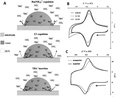 | ||
| Fig. 25 Cyclic voltammetry of aqueous, microscopic Ru(NH3)6Cl2 droplets in DCE adsorbed on a glassy carbon electrode: (A) schematic representation of the three different mechanisms, to maintain electroneutrality within the aqueous droplet during Ru3+ reduction. (B) CV of Ru(NH3)6Cl2 confined within surface immobilized, aqueous microdroplets at 0.05 M, (thin line) 0.1 M (dotted line) and 0.2 M (thick line) of TBAClO4 in the DCE bulk phase on a glassy carbon electrode vs. SCE. (C) CV of Ru(NH3)6Cl2 confined within surface immobilized, aqueous microdroplets, without (dotted line) and with addition of 0.1 M KCl as a supporting electrolyte (thick line) confined in the aqueous phase, at 0.2 M TBAClO4 in the DCE bulk phase on a glassy carbon electrode vs. SCE. Reproduced with permission from T. J. Davies, S. J. Wilkins and R. G. Compton, J. Electroanal. Chem., 2006, 586, 260.172 | ||
This example highlights the ability of cyclic voltammetry to characterize large numbers of nano entities at once: However, to achieve insights into the single droplet level, more localized probing techniques are required to analyse individual entities.
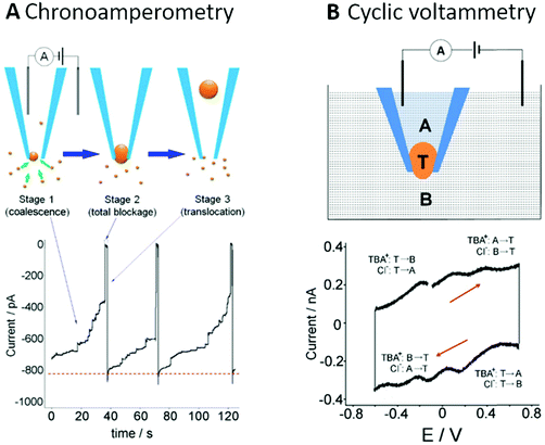 | ||
| Fig. 26 Electrochemical sensing of single droplets by blocking: the ionic current of TBACl in water between two Ag/AgCl electrodes, one within the bulk phase, the other one confined within a quartz nanopipette with 200 nm orifice diameter is damped by the blockage of the orifice by adsorbed toluene + IL-PA droplets. (A) Amperometric current response of TBACl ionic current damped by adsorption and following droplet coalescence (stage 1). Complete blockage of the orifice exhibits a recorded current of 0 pA (stage 2), as the coalescent droplet translocates from the orifice into the pipette and the ionic current is fully restored (stage 3). (B) CV of ion transfer of TBA+ and Cl− through a toluene +IL-PA coalescent nanodroplet, completely blocking the nanopipette orifice. Red lines indicate the scan direction. The recorded scan-rate is 20 V s−1. Reproduced with permission from C. G. Gunderson, Z. Peng and B. Zhang, Langmuir, 2018, 34, 2699.174 | ||
The employment of a two-electrode setup, containing only Ag/AgCl quasi reference electrodes, one of them placed within the capillary and one within an aqueous 5 mM TBACl solution, guaranteed a weakly potential-dependent background current, which can be allocated to ionic current of the supporting electrolyte. The gradual change of the time resolved current response indicates the adsorption of single droplets on the capillary wall. These coalesce with incoming droplets and, hence, grow over the course of a 40 s experiment, while the measured current is gradually decreasing. After 40 s, the growing droplet reaches a critical size to completely block the nanopore and shuts off the electrochemical signal. Driven by osmotic pressure, the blocking droplet eventually deforms and detaches from the capillary walls, translocating into the bulk of the capillary (Fig. 26A). This results in a re-opening of the nanopore and an immediate spike in the current response. The authors attributed this to a potential dependence of the coalescence, as the blockage led to a 99% decrease of baseline-current at −0.2 V and a 87% decrease at −0.4 V vs. Ag/AgCl. In addition to these electrochemical measurements, the authors traced the droplet's translocation by fluorescence imaging. Similar to measurements on a supported liquid membrane system by Velický et al.,175 Zhang and co-workers used the entrapped state of the droplet to probe ion transfer trough the liquid/liquid interface. In the short dwell time of the full-grown droplet, they completed a voltammetric cycle by ramping the potential from 0.8 to −0.8 V with a scan rate of 20 V s−1.
The corresponding CV clearly exhibits characteristic peak currents associated with the transfer of TBA+ and Cl− from bulk solution in the droplet and vice versa (Fig. 26B). The difference in current responses between single molecules and aggregates passing a nanopipette orifice can also be utilized in medicinal research. For instance, Yu et al. utilized it to study the medical aggregation behaviour of amyloid-β relevant for Alzheimer's disease.176 Analogous to nanocapillaries, micro- or nanofluidic devices are used to detect the current response of single, transient droplets, as they temporally block the diffuse layer of a sensing electrode.177 Recent developments in the fabrications of such nanofluidic devices109,178 will soon lead to lower detection limits, allowing the recording of nanoscopic droplets. We consider these devices to play a crucial role in the investigation of single entity confinement by then.
| fems = 4DemsCemsreNA | (15) |
Here fems is the collision frequency, Dems and Cems are the diffusion coefficient and concentration of the nanodroplets within the nanoemulsion, and re is the electrode radius. The stochastic nature of impacts, e.g. driven by Brownian motion, causes a multitude of single events within a short time period. These collision events are observable as short current spikes in chronoamperograms. The high frequency and random nature of collision events allows statistical investigation of peak size, peak shape and dwell time, marking single entity impacts as a versatile probing tool for colloid nano entities.181 In case of total conversion, the transferred charge during a collision event can be used to calculate the size of the nano entity, dependent on its activity or the activity of redox-active species within its cavity.
 | (16) |
Here ddrop is the diameter of the nano droplet, Q is the measured charge, F the Faraday constant, and credox is the concentration of the electrochemically active species inside the droplet. For setups with sufficiently high time resolution,182 conclusions about the nature of the probed electrochemical process can be drawn from the peak shape. Typically, a nearly vertical change from the background current occurs as the entity collides with the electrode. If followed by a steep current decay, the peak shape indicates a faradaic transformation of the target species and the rapid consumption of this species.6 If instead a plateau-shaped current response follows, this indicates a catalytic nano-impact. Such an event occurs for entities that catalyse the redox reaction of species present in the bulk solution.183 Blocking impacts are another common case of single entity electrochemistry. There the associated current response is also stepwise, but the current signal decreases during the experiment, as the collision with the UME blocks an electrochemical process at the affected electrode region.
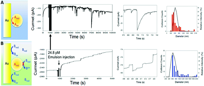 | ||
| Fig. 27 Electrochemical single entity impact method adjusted for nano- and microscopic droplets: collision measurements of Fc filled toluene + IL-PA droplets in aqueous solution, at a biased 10 μm Au electrode. (A) Schematic representation and current response of single droplets, impacting at the Au UME, held at a potential of 0.5 V vs. Ag/AgCl, sufficient to trigger the oxidation of the encapsulated Fc. Schematic representation of the oxidation process during collision (left), over the whole recorded chronoamperogram, incl. a zoom in on a single impact event (middle) and comparison of estimated droplet size with dynamic light scattering (DLS) data (right, red bars and line respectively). (B) Schematic representation and current response of single droplets impacting the Au UME, held at a potential of 0.2 V vs. Ag/AgCl, not sufficient to trigger the oxidation of the encapsulated Fc. Schematic representation of the blockage of the electrode for background effects (left), complete recorded amperogram incl. zoom in on a single impact event (middle) and comparison of estimated droplet size with DLS data (right, blue bars and line respectively). Reproduced with permission from B.-K. Kim, A. Boika, J. Kim, J. E. Dick and A. J. Bard, J. Am. Chem. Soc., 2014, 136, 4849.184,185 | ||
Bard and co-workers first applied the concept of single entity impacts to a colloidal confinement system, as they studied single colloid collisions of Fc filled toluene droplets at a UME.184,185 Utilizing the well-known redox-process of Fc encapsulated in toluene + IL-PA, H2O as bulk phase and a 10 μm Au UME as a working electrode, they showed that the above-described impact shapes also fit to explain the current responses of small droplets (Fig. 27).
| Fc ⇌ Fc+ + e− 0.4 V vs. NHE | (17) |
Holding the WE at 0.2 V vs. Ag/Ag+ resulted in a step-like current response associated with a blocking collision, as this potential is not sufficient to oxidize the entrapped Fc. By increasing the potential to 0.4 V vs. Ag/Ag+, clear, blip shaped current spikes arise from single event collisions, as the Fc within the droplets is completely oxidized to Fc+. Using eqn (16), the size of impacting droplets was estimated to range from 300 nm to 1000 nm in diameter, which is in good agreement with the dynamic light scattering (DLS) measurements of the nanoemulsion. In contrast to the DLS measurements, the electrochemical investigation also reveals droplets of more than 2 μm in diameter and exhibits a lognormal-type size distribution. This distribution can be associated with nano entities growing via the processes of Ostwald ripening and coalescence.186 The observed behaviour shows a major weakness of the nano-impact method, i.e. that an electrolyte solution needs to be identified that allows charge transfer between electrode and redox species to occur, without altering the nano entities previous to their investigation. In the reported work, the increased ionic strength of the bulk electrolyte solution, induced particle aggregation, and therefore the detection of larger particles.
Liu et al. extended the single droplet nano-impact method, by applying single colloid fast-scan cyclic voltammetry (FSCV) to it.187 By cycling a carbon UME 0.3 to 1.3 V vs. Ag/Ag+ at a scan rate of 40 V s−1 they resolved multiple CV cycles during the collision of toluene droplets filled with rubrene (Rb) as redox-active species and IL-PA as supporting electrolyte (Fig. 28A). In contrast to regular CV measurements, the current is plotted versus time (Fig. 28B-I). The resulting chronoamperogram is treated with a background correction to identify single event blips (Fig. 28B-II). These are processed by a Fourier transform to obtain the first cycle for every impact even (Fig. 28B-III). To prove the viability of the processing method, the resulting CVs were compared with results from finite element simulations.
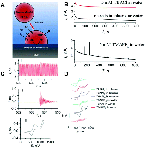 | ||
| Fig. 28 Combination of single entity impact experiments with fast CV methods for the investigation of ion transfer into nanodroplets: toluene droplets filled with Rb and IL-PA in an aqueous bulk collide with a biased carbon UME. (A) Schematic representation of the maintenance of electroneutrality during the oxidation of rubrene encapsulated within the droplet by ion transfer trough the toluene/water interface. (B) Schematic description of FSCV background subtraction shown in three steps: the raw current–time profile of a nanoemulsion-electrode collision event (I), subtraction of the background (II) and derived CV at 56 V s−1 (III). (C) FSCV derived current response for 5 mM Rb filled toluene droplets colliding with a carbon UME at 0.8 V vs. Ag/AgCl wire for different electrolyte concentrations and types. (D) Derived CVs from FSCV for rubrene encapsulated in toluene for different supporting electrolytes in the bulk and the confined phase. Reproduced with permission of C. Liu, P. Peljo, X. Huang, W. Cheng, L. Wang and H. Deng, Anal. Chem., 2017, 89, 9284.187 | ||
Using FSCV, the authors showed a significant change in the redox behaviour of rubrene, dependent on the used supporting electrolyte, as peak position and separation change. By varying the lipophilicity of the ions forming the supporting electrolyte, they identified the conservation of charge by ion transfer at the liquid/liquid interface as the rate-determining step in the occurring redox process. Hereby, the shift of the half-wave potential decreased with increasing anion- and decreasing cation lipophilicity (Fig. 28C and D).
Single entity electrochemical impacts can also be used to evaluate critical micelle concentrations and micelle sizes by electrochemical transformation of redox-active surfactant species, as shown by Compton and Toh.188 The authors oxidized the bromide in cetyltrimethylammonium bromide (CTAB) surfactants, contained in large micelles and liposomes in the aqueous phase. The single soft particle collision method was also applied to a variety of soft nanoparticles,189 including biologic entities, such as viruses,190,191 enzymes192 and vesicles.173
4.4. Confinement effects in soft particles
 | (18) |
 | (19) |
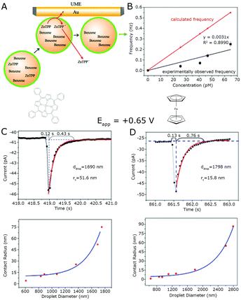 | ||
| Fig. 29 Single entity impacts of benzene droplets encapsulating different hydrophobic species on Au UME: (A) schematic description of the oxidation of ZnTPP and following escape of ZnTPP+ from the droplet during collision. (B) Comparison of calculated and experimentally observed frequency of collision events at different emulsion concentrations for ZnTPP filled benzene droplets on a 0.65 V vs. Ag/AgCl biased Au UME. (C) Current response of a single ZnTpp containing benzene droplet colliding with the biased Au UME, together with evaluated droplet and droplet/electrode interface-area estimated from eqn (18). Derived droplet/electrode contact radius in dependence of droplet diameter for ZnTpp in benzene nanoemulsions on Au UME at 0.65 V vs. Ag/AgCl. (D) Current response of a single Fc containing benzene droplet colliding with the biased Au UME, together with evaluated droplet and droplet/electrode interface-area estimated from eqn (18). Derived droplet/electrode contact radius in dependence of droplet diameter for Fc in benzene nanoemulsions on Au UME at 0.65 V vs. Ag/AgCl. Reproduced with permission from Y. Li, H. Deng, J. E. Dick and A. J. Bard, Anal. Chem., 2015, 87, 11013.193 | ||
Here rmd is the radius of the micro disk electrode and Di and ci are the diffusion coefficient and concentration of the encapsulated species, respectively. By using eqn (18) with the diffusion coefficients derived from eqn (19), they estimated the electrode/droplet contact area for every collision event from the tail shape of the single entity impact events (Fig. 29C and D). By using eqn (16) to calculate the droplet size and (18) to calculate the contact area, an exponential dependency of the contact area with droplet diameter was found (Fig. 29C and D). This effect correlates with the wettability of the used Au UME as the respective contact area of more hydrophilic benzene droplets is bigger than the respective contact area of a cyclohexane droplet of the same size. Notably, no correlation between electrode wettability and the deviation of calculated impact frequency from the experimentally observed one was found (Fig. 29B).
Finite element simulations are often used to evaluate peak currents according to the bulk electrolysis model using the steady state current of a micro disc electrode and taking the rapid change of ccS in the cavity into account.194 In their recent publication, Glasscott et al. derived an analytical solution for the nucleation of H2PtCl6 encapsulated within a water/glycerol nanoemulsion in a 100 mM TBAClO4 in DCE bulk solution.195 Considering bulk electrolysis and the classical growth theory described by Kucernak and co-workers,196 they formulated equations that describe the complete current response of single impact and nucleation events for nano droplets of 200 to 1000 nm radius with outstanding precision.195 They derived the following equations for the two limiting cases of mass transport limitation and kinetic limitation.
 | (20) |
 | (21) |
 | (22) |
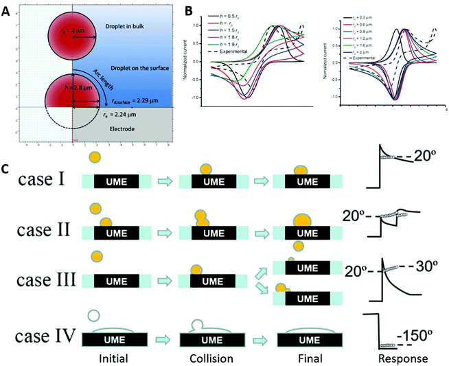 | ||
| Fig. 30 Investigation of the effects of droplet deformation on the current response for a droplet-electrode collision event: (A) Schematic description of the used droplet geometry for the simulation model, V is maintained from droplet in bulk to droplet on the surface, leading to a change in rdrop by changing hhS according to eqn (22). (B) Comparison of simulated CV and experimental CV of a single Rb+ IL-PA filled benzene nanoemulsion, carbon UME collision event, potential is given vs. Ag/AgCl. Simulated CV shape in dependence of droplet deformation (variation of h) and size (variation of rd) is shown. (C) Four mechanisms of droplet-electrode collision events are derived from experimental FSCV data. Reproduced with permission from C. Liu, P. Peljo, X. Huang, W. Cheng, L. Wang and H. Deng, Anal. Chem., 2017, 89, 9284.187 | ||
By varying hhS from 50% of the original droplet radius up to 190%, the resulting shape of the adsorbed hemisphere was stepwise changed from a lying to a standing ellipsoid, while the total volume was maintained. Utilizing this approach the authors showed an increasing current and decreasing peak width with reduced hhS (Fig. 30B). Similar considerations can also be found in the work of Glasscott et al.158
While the peak position and separation remained similar for most considered values of hhS, the peak separation is reduced for hhS = 0.5rd and increased for hhS = 1.9rd, where the peak position is also shifted to more negative potentials. Similar results were observed by varying rd of the original droplet from 0.3 μm to 2 μm. With increasing rd, the peak current and width of the simulated CV increased (Fig. 30B). The peak position and separation remained similar, except for rd = 0.3 μm, exhibiting a strongly reduced peak separation. Both cases imply a limiting case for mass transport if one of the dimensional parameters is below 300 nm. The experimental data cannot be fit to a single one of the studied cases, but resemble a convolution of multiple cases, which might imply a constant change of droplet shape during electrolysis. Using the different observed peak shapes, the authors were also able to derive various cases of electrode/droplet collisions (Fig. 30C). They found that a step-like current increase, coupled with an initial exponential current decay, can be associated with the impact of a single droplet (case I), implying a high dwell time for droplet/electrode contact. A twin peak with a small capacitive spike on the second blip was ascribed to the coalescence of two droplets on the electrode (case II). The case of a prolonged, steeper exponential current decay, while arriving at lower background current increase compared to case I, was attributed to the splitting of the droplets upon collision with the electrode (case III). A blocking impact can be observed for the collision of toluene droplets, without a redox-active species included (case IV).
Considering the behaviour of a surfactant stabilized droplet, Li et al. simulated the current response of an example redox-active species confined within a liposome of 100 nm diameter.197 To simulate a protected droplet, the cavity walls were designed as no flux boundaries, prohibiting mass transfer of encapsulated species into the bulk. A hole with a 50 nm diameter at the droplet surface allows mass transfer through the droplet/bulk interface to mirror a nanopore opening behaviour upon electrode collision. This was previously shown by several groups and associated with intrinsic properties of the vesicle solution198 and the strong electric field applied on the wall-material of nano-scale membranes in proximity to a biased electrode.175
By comparing peak sizes and shapes for single entity impacts of dopamine confined in liposomes, peptide-covered liposomes and chromaffin cells, Lovrić et al. demonstrated the potential and wall-material dependence of pore formation.199 Despite a similar vesicle diameter (≈330 nm), the average full width half maximum (FWHM) of a single impact event increased from 0.57 ms for the liposome control to 7.2 ms for chromaffin. The main contribution for this elongated time was found in the slow decay after the maximum, suggesting a mass transport governed release, which was attributed to the dense core within chromaffin. The authors concluded that an increase in thickness of the vesicle wall decreased both, the probability of pore formation and the pore opening time. The authors simulated the peak shape for varying vesicle positions on disc- and conic electrodes and different pore positions on the vesicles (Fig. 31A). On disk electrodes, the pore position did not alter the peak shape significantly (Fig. 31B), while their simulations for conical electrodes revealed a strong dependence of both, vesicle and pore positions (Fig. 31C and D). The influence of the pore position is most pronounced for vesicles at the cone tip (Fig. 31C).
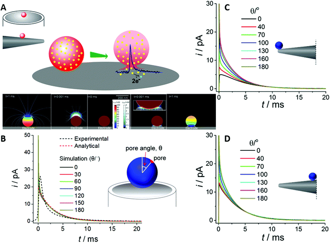 | ||
| Fig. 31 Finite element simulations of current dependency on pore position in liposome/electrode collision events: (A) schematic representation of the simulated system: a redox-active species encapsulated in 100 nm liposome is set to be completely transformed upon contact with the electrode, the redox-active species is set to only leave the liposome through a pore only and bulk solution is set to be permeable for redox-active species. Simulated concentration profile changing over time, as the redox-active species is consumed, for pore facing away from the electrode (bottom left) and pore in contact with electrode (bottom right). (B) Simulated current response of single liposome collision events on micro disk electrode at different pore positions (θ). (C) and (D) Simulated current response of single liposome collision events on a micro pipette electrode at different pore positions (θ) and droplet positions. Reproduced with permission from X. Li, L. Ren, J. Dunevall, D. Ye, H. S. White, M. A. Edwards and A. G. Ewing, ACS Nano, 2018, 12, 3010.197 | ||
In conclusion, the authors showcased that electroporation is strongly influenced by electrode geometry and, thus, highlights the importance of cell design in such experiments. It is worth noting, that the simulation data did not match the experimental behaviour at any point. Assuming that this does not have to be correlated to strong filtering or smoothing of the data, this suggests the appearance of nanoscale effects during single entity impact experiments of dopamine containing vesicles that cannot be considered by means of microkinetic simulations and might be attributable to confinement.
In contrast to the nano pore formation discussed above, Compton and Cheng proposed a “full collapse fusion” mechanism for the collision of a single liposome with a biased WE.200
For confined electrochemically active species that are insoluble in the bulk solvent, their release through a nanopore is prohibited. Therefore, a faradaic process can only occur through the interface formed by the electrode and the cavitand walls, which is highly dependent on the wall material. This causes geometric effects, such as wall thickness and rigidity, to influence the probability of electron transfer processes. Increased wall complexity often leads to an increase of the zeta (ζ) potential and, thus, the overpotential necessary to initiate the faradaic process.
Sabaragamuwe et al. investigated the influence of the wall thickness on Fc oxidation in castor oil-filled (DOS) nanocarriers of around 40 nm, which were protected by the surfactant F-127 and supported by potassium tetrakis[3,5-bis((trifluoromethyl)phenyl)borate] (KTFPB).201 An insufficient amount of F-127 led to surfactant stabilized droplets with two distinct shells, an outer, perforated shell, formed by F-127 and a second, closed shell formed by encapsulated TFPB−, gathering at the outer boundaries of the cavitand. In contrast to the freely moving TFPB− in sufficiently protected droplets, this leads to an increased wall thickness, visible via stained EM measurements and to an increased ζ-potential, prohibiting the oxidation of Fc on the biased UME (Fig. 32A). At a constant bias of 0.85 V vs. Pt/Pt+, no current response was found for the multiwall nanodroplets, while discrete collision events with the Pt UME were recorded after the injection of the single-walled species (Fig. 32B). A capacitive change in the background current during the injection of the latter was associated with the double layer reorientation due to free F-127 in the aqueous bulk. Applying a bias of 1.0 V vs. Pt/Pt+ caused current spikes due to Fc oxidation in the multiwall microemulsions (Fig. 32C). These spikes were strongly permuted in comparison to the unlayered species, the latter exhibiting a slow peak rise, followed by a sharp decrease. This indicates a kinetically controlled impact event, as shown above.195 Notably, the obtained small size distribution is quite similar for both species in DLS and single entity electrochemistry (SEE) (Fig. 32C). In comparison to other SEE measurements shown in this review, especially for surfactant free nanodroplets, the obtained size distribution is very small, suggesting highly stabilized nanocarriers during the experiment.
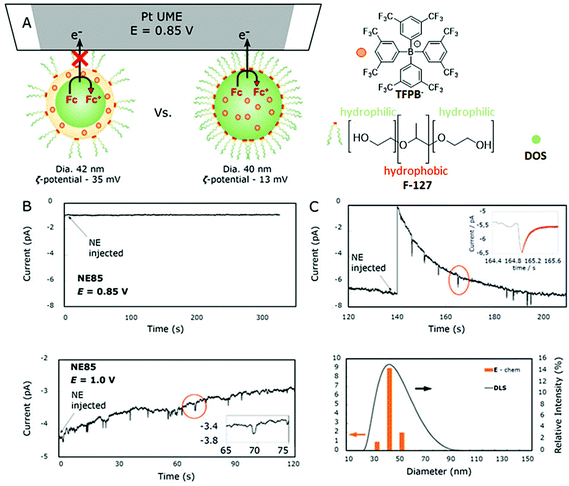 | ||
| Fig. 32 Altered cavity accessibility with interface intrinsic change in zeta potential: (A) schematic description of Fc filled DOS droplet protected with the surfactant F-127 and supported with KTFPB colliding with Pt UME biased at 0.85 V vs. Pt QRE in at high (right) and low (left) concentrations of F-127. (B) Current response of single collision events of Fc encapsulated in a surfactant capped cavity with a zeta potential of −35 mV at 0.85 V (top) and 1.0 V (bottom) vs. Pt QRE with a Pt UME. (C) Current response of single collision events of Fc encapsulated with a zeta potential of −15 mV at 0.85 V (top) vs. Pt QRE with a Pt UME and microemulsion size evaluated from SEE (orange bars) and DLS (line). Reproduced with permission from S. G. Sabaragamuwe, D. Conti, S. R. Puri, I. Andreu and J. Kim, Anal. Chem., 2019, 91, 9599.201 | ||
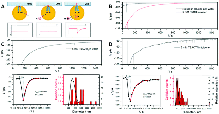 | ||
| Fig. 33 Ion transfer across the toluene/water interface probed by SEE: toluene nanoemulsions encapsulating 5 mM rubrene +400 mM IL-PA, dispersed in a water bulk collide with a Pt UME at 0.9 V vs. Ag wire. (A) Schematic representation of the mechanism to maintain electroneutrality during the faradaic process, A characterizes the hydrophobic rubrene and thus is not able to leave the benzene droplet, exhibiting no current response (left), a hydrophilic anion D− is not able to enter the droplet, leading to no current transfer (middle). If either a less hydrophilic anion N− or a less hydrophobic cation X+ can enter or leave the droplet, the electroneutrality can be maintained and a current response is observable. (B) Chronoamperogram of the rubrene toluene emulsion droplets in water containing no supporting electrolyte in both phases (black line) and 5 mM NaOH in the aqueous phase (red line). (C) Chronoamperogram of rubrene toluene emulsion droplets in water containing 5 mM TBAClO4 in the aqueous phase (top), zoom in on the current response of a single collision event and derived droplet size and droplet/electrode contact radius (bottom left), particle size distribution derived from SEE (red bars) and DLS (black line) (bottom right). (D) Chronoamperogram of the rubrene toluene emulsion droplets in water containing 5 mM TBAOTf in the toluene droplet (top), zoom in on the current response of a single collision event and derived droplet size and droplet/electrode contact radius (bottom left), particle size distribution derived from SEE (red bars) and DLS (black line) (bottom right). Reproduced with permission from H. Deng, J. E. Dick, S. Kummer, U. Kragl, S. H. Strauss and A. J. Bard, Anal. Chem., 2016, 88, 7754.202 | ||
Since electroneutrality must be maintained, the charge was balanced by supporting electrolyte ions crossing the liquid/liquid interface. The two cases of cations (C+) leaving the toluene droplet and anions (A−) entering the organic droplet during the rubrene (Rb) oxidation were investigated.
| Rb(o) + C+(o) ↔ Rb+(o) + C+(w) + e− | (23) |
| Rb(o) + A−(w) ↔ Rb+(o) + A−(o) + e− | (24) |
At a constant potential of 0.9 V vs. Ag/Ag+ they found no current blips for the highly hydrophilic supporting electrolyte NaOH, which was dissolved in the aqueous phase (Fig. 33B). In contrast, the usage of tetrabutylammonium-perchlorate (TBAClO4) and sodium tetraphenylborate (NaTPB) as an aqueous phase supporting electrolyte led to the observation of current transients (Fig. 33C), associated with droplet/electrode collision events. An ion transfer through the water/toluene interface is permitted for the less hydrophilic ClO4− and TPB− anions, while prohibited for OH−. Also, for low concentrations of TBA+ and tetra hexyl ammonium (THA+) within the toluene nanodroplet, ion coupled electron transfer (Fig. 33D) with clearly distinguishable current blips was observed for the more hydrophilic TBA+. Entangled current steps, blips, and plateaus were observed for THA+. Utilizing the average, normalized current transient for single droplet collisions of the TBAClO4 system at different potentials, the authors estimated a bulk voltammogram for encapsulated rubrene. The difference of 0.153 V, found in the half-wave potential of the estimated voltammogram, compared to a similar bulk voltammogram of rubrene, allowed to calculate a formal ion transfer potential of 0.754 V vs. NHE for TBA+ .
.
 | (25) |
 ,
,  the potential of the used reference electrodes, respectively. The parameters c0R, cTBA+, Dr and DTBA+ are the concentration and diffusion coefficients of rubrene in the bulk and TBA respectively, the superscripts “o” and “w” denote the organic and aqueous phases, respectively. Fostering the generality of the described findings, Zhang et al. described an ion coupled electron transfer for ferrocyanide, confined in protected water in oil emulsions.194 For ion transfer from an organic bulk phase into a confined aqueous phase, they found a promotion of the faradaic reaction by weakly hydrophilic and water soluble supporting electrolytes. The authors increased the scope of investigated ions and also considered the influence of emulsifying species within the cavitand. Investigations of ion transfer across the oil/water interface were recently presented for bromide204 and acetate.187 In contrast to this, Peng et al. presented a quasi-reversible Fc/Fc+ redox process for Fc confined in toluene nanodroplets, maintaining electroneutrality through the surfactant Tween20.205 They proposed a liquid/liquid interface electron transfer by a respective capture and release of potassium ions in the electrical double layer of the surfactant.
Recent developments in the stabilization of sessile, microscopic droplets, which are located on the working electrode, allow a direct measurement of the ion transfer potential at the ITIES, which is not constrained to faradaic processes.203,206
By applying a sufficient potential between an electrode located in the organic phase and another electrode located in the aqueous phase, ion transfer through the ITIES can be observed. If the electrolyte salt in the organic phase consists of a strongly hydrophobic ion and a weakly hydrophobic counterion, the latter passes the ITIES and is transferred into the aqueous phase at a sufficient driving potential. This leads to a charge separation and double layer reorientation which can be detected via the current response.207 As the transferred charge is small and high capacitance arises from the liquid/liquid interface, this process is difficult to probe by means of cyclic voltammetry or microscopic techniques, like SECM90 alone. By combining ITIES measurements on sessile droplets with the single entity impact method for solid nanoparticles208 and electrolyte filled nano emulsions,206,209 the sensitivity for ion transfer is greatly enhanced. Laborda et al.206 observed discrete events for electrolyte filled, microscopic DCE droplets, dispersed in an aqueous phase, colliding with a sessile DCE droplet. By adjusting the hydrophilicity of ions confined in DCE droplets and tuning the applied potential, the authors created two different cases of ion transfer during one collision event (Fig. 34A). If the applied Galvani potential (Δϕapp) is more negative than the ion transfer potential for both, electrolyte cation  and anion
  , the cation is transferred into the aqueous phase, leading to a charge separation and an observable current spike. For values of Δϕapp lying between
  and
and  both ions are either transferred into the aqueous phase (for
  ) or remain in the organic phase (for
  ), leading to a net charge transfer of zero. Positive current spikes were observed for the transfer of chloride into the aqueous solution at an applied Galvani potential more negative than
  (Fig. 34B), as positively charged TDDA+ remained in the organic phase. Notably, the recoded frequency and average transferred net charge is highest for a small overpotential. The usage of the weakly hydrophobic cation TMA+ and the highly hydrophobic anion TClPB− led to negative current spikes for
  , as TMA+ is transferred into the aqueous phase and to no current spikes for
  (Fig. 34C).
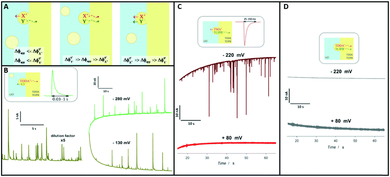 | ||
| Fig. 34 Single emulsion impacts of DCE nanoemulsions on a DCE/water ITIES: microscopic nanoemulsions of DCE containing supporting electrolyte of different hydrophilicity are suspended in an aqueous LiCl phase, the macroscopic DCE phase is supported by TDDATClPB, both phases contain a Pt wire and an Ag wire as working and quasi reference electrode, respectively. (A) Schematic description of the ongoing ion transfer in dependence of the potential difference for applied potential and the different ion transfer potentials across the ITIES, light blue marks the aqueous phase, light yellow marks the DCE phase. (B) Observed amperometric current response of DCE nanoemulsions, encapsulating TDDACl colliding with the ITIES at different applied potentials. (C) Observed amperometric current response of DCE nanoemulsions, encapsulating TMATClPB colliding with the ITIES at different applied potentials. (D) Observed amperometric current response of DCE nanoemulsions, encapsulating TDDATClPB colliding with the ITIES at different applied potentials. Reproduced with permission from E. Laborda, A. Molina, V. F. Espín, F. Martínez-Ortiz, J. García de la Torre and R. G. Compton, Angew. Chem., 2017, 129, 800.206 | ||
For strongly hydrophobic anions and cations confined within the colloid DCE droplets, no current spikes were observed for Galvani potentials higher or lower than the formal transfer potential, as both ions either stayed within the organic phase or were transferred into the aqueous phase, respectively (Fig. 34D). Taking the presented method one step further, Samec and co-workers investigated single ITIES collision events within a sessile aqueous microdroplet, filled with smaller, salt filled DCE microdroplets.209,210 They observed a sharp decrease in the open circuit potential upon impact, followed by a strongly restrained current drop during collision events. This was associated with a spontaneous reorganization of the electrical double layer at the ITIES of the sessile droplet, as Cl− was egressed in the DCE bulk phase and TDDA+ gathered on the outer boundaries of the water droplet, leading to a Cl− migration to the interface for charge compensation. As TDDA+ and Cl− disperse into the DCE bulk, the positive charge on the droplets outer boundaries decreases, leading to a relaxation of the double layer to its original state. These findings suggest the formation of a temporary, dense double layer, dependent on size and curvature of the sessile droplet.
4.5. Conclusion
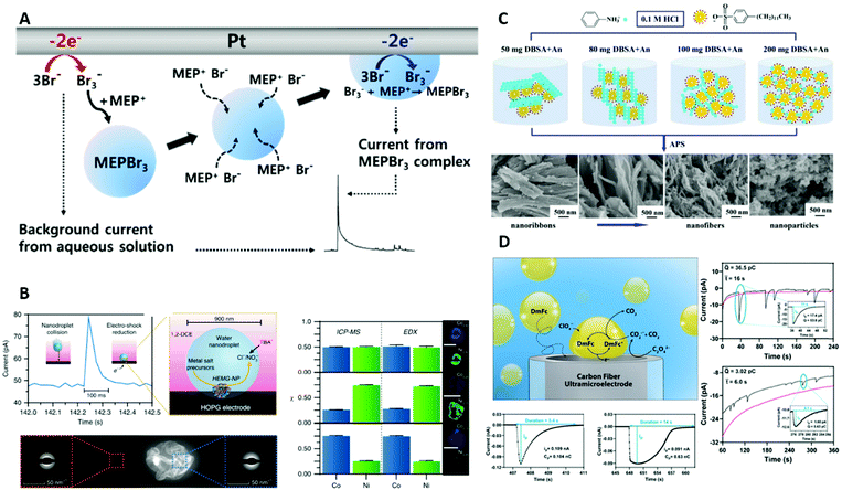 | ||
| Fig. 35 Recent developments in the field of single entity colloid confinement in electrochemical systems, showcasing future directions: (A) operando formation of nanoemulsions during Br− oxidation in aqueous solution on a Pt electrode, exploitable as nanocarriers and accumulators for Br− in battery applications. Reproduced with permission of S. Park, H. Kim, J. Chae and J. Chang, J. Phys. Chem. C, 2016, 120, 3922.213 (B) Rapid reduction and subsequent nucleation of several precursor salts encapsulated in aqueous micro droplets by bulk electrolysis leads to formation of kinetically controlled mixed metal nanoparticles. Reproduced with permission of M. W. Glasscott, A. D. Pendergast, S. Goines, A. R. Bishop, A. T. Hoang, C. Renault and J. E. Dick, Nat. Commun., 2019, 10, 2650.214 (C) Control of polyaniline polymerization behaviour by variation of spacer volume, realized through DBSA microemulsions. Reproduced with permission from L. Ren, G. Zhang, H. Li, D. Hu and S. Dou, Int. J. Electrochem. Sci., 2019, 238.215 (D) Strong signal enhancement of the DmFc electrochemical oxidation for DmFc encapsulated in DCE microdroplets amplified by reactant regeneration through radical annihilation promoted by oxalate at water/DCE interface. Reproduced with permission of R. Kazemi, N. E. Tarolla and J. E. Dick, Anal. Chem., 2020, 24, 16260.216 | ||
Since bulk electrolysis of the droplet is finished within milliseconds and no further electron transfer occurs, the encapsulated metal atoms maintain their initial, amorphous configuration, instead of relaxing, even if other configurations would be thermodynamically more favoured. These kinetically controlled particle configurations remain amorphous, in contrast to the highly oriented state, which is usually favoured for metals. With decreasing metal/metal solubility, the formed nanoparticles become high entropy alloys, usually known to only form under extreme conditions, such as carbon shock nucleation.220 Using the unique properties of droplets for spacing and patterning, Ren and co-workers synthesized electrode materials, ranging from lamellar structures over nanotubes and nanofibers to nanoparticles by varying the droplet concentration.215 An increasing concentration of dodecylbenzene sulfonic acid (DBSA) was dispersed in an aqueous solution of aniline at a low pH value, leading to the formation of an aniline/DBSA-micellar network, forming sheets, broad and thin chains and distributed spherical droplets of aniline between the micelles (Fig. 35C). In the presented work, the polymerization was induced by a chemical compound, but this process might be replaced by electropolymerization221 for a more controlled electrode decoration. Recently, Dick and co-workers216 presented a promising technique to greatly amplify electrochemical sensitivity in single-droplet impact measurements by radical amplification, usually known from nano gap experiments.222
Toluene nanocarriers, encapsulating bis-(pentamethylcyclopentadienyl) iron (DmFc) were dispersed in an aqueous solution supported by sodium perchlorate. Upon collision, the perchlorate serves as a supporting electrolyte and maintains electroneutrality during the oxidation of DmFc by transferring into the droplet. At potentials of +0.8 V vs. Ag/AgCl on a Pt UME, oxalate is oxidized and forms the radical form of CO2. By traversing the water/toluene interface, these radicals reduce the electrochemically generated DmFc+ back to DmFc (Fig. 35D). Due to the small scale of the system, diffusion is very efficient, granting a highly enhanced transferred charge per collision event. As DmFc is oxidized at the electrode, reduced by CO2˙− and re-oxidized in a sequence, signals are amplified by up to 5 orders of magnitude. In combination with the ability to accumulate certain pollutants,156 as mention above, this exciting technique might lead to detection limits in the sub femtomolar region. Moreover, the amplification allows for detection of much lower amounts of redox-active species, making single entity impact methods available for smaller systems, enabling the investigation of highly confined clathrates and nanometric micelles.
The formation of unexpected products and unknown electron transfer steps within some of the discussed confined systems, together with the high local electric fields applied by spontaneous double layer reformations, indicate a significant, catalyst-like, enhancement of the reaction rates of confined molecules.
5. Future perspectives
In the four sections of this educational review, we discussed the different types of confinement, the geometries and experiments considered as confined in an electrochemistry context, how to measure the effects of confinement and how they could manifest in an electrochemical experiment. We reason, how confinement might influence the results of SECM and nanogap experiments and why even electrochemical reactions in suspensions of micrometre sized droplets could be considered ‘confined’ electrochemistry in a non-classical sense. Additionally, we suggest how the rapid development in experiment design and nano-device fabrication will lead to significantly improved sensitivity. This will eventually enable experimental investigations of the short-range effects induced by sub nanometre geometric confinement and be predictable by theoretical models. To provide an overview of how to tackle confinement in modern electrochemistry, we have discussed publications that, in our opinion, give a flavour of the exciting progress that electrochemistry under confinement will likely undergo in the next years. Addressing this anticipated progress, we want to put a special emphasis on the upcoming field of combining electrochemistry and highly-ordered two-dimensional structures, such as metal organic frameworks (MOFs) and covalent organic frameworks (COFs), briefly mentioned in the sub-nanometre Section 3.4 of this review. First results of electrode materials covered with such structures often show a remarkable increase in catalytic activity of the respective electrode material, due to a change in free energy of adsorption of either reactants or products induced by the polarity of functional groups within the wall material.223 Recently, Lotsch and co-workers studied the role that interactions of functional groups within three-dimensional COFs play in photocatalysis.224 While newly developed experimental methods allow electrochemical investigations of smaller and more confined systems, providing the ability to correctly analyse the obtained data, electrochemical measurements of complex systems yield convoluted signals. The latter contain a multitude of individual influences, difficult to properly dissect and evaluate, as demonstrated for instance in the works of Bard193 and Dick.195 They avoided wall molecules and utilized large curvature and droplet surface areas, easily transferable electrolyte ions and small concentrations to reduce interface effects. Additionally, geometric effects were minimized, as the usage of large droplets reduced the influence of droplet deformation and increased the dwell time of droplets on the measurement electrode, while low droplet concentrations were used to minimize merging behaviour. Together with utilising rather simple electrochemical reactions, the complexity of the investigated system was minimized. This simplification enabled the authors to formulate their rate determining bulk electrolysis theory in dependence of the electrode/droplet interface areas. The above-mentioned effects influencing the interface were excluded, as a precise knowledge of the interface properties was pre-requisite for the authors to gain meaningful insights from the detected signal. For more complex systems, this often leads to circular references, as the interface area, which is often estimated based on assumptions, is then used to interpret the unknown properties dictating its behaviour. Investigating the measured signal by numerical methods225 requires a simplification of the system based on assumptions, which may reduce the detectable influences for a specific simulation design.226 A reliable method to experimentally overcome the problem of too many unknowns lies in the quickly developing field of correlated, complementary electrochemical and spectroscopic methods.227–229 For these experiments, the knowledge gain from one method is used to interpret the signal of the other method. A very recent example for simplifying the interpretation of electrochemical data by fixing one of its parameters to a value, which is known via spectroscopic measurements in nanoemulsion electrochemistry, was presented by Dick and co-workers.230 They used electro-generated chemiluminescence of [Ru(bpy)3]Cl2 confined within a water droplet to optically observe the droplet/electrode interface. Using this technique, the contact area was acquired independently from electrochemistry, reducing the amount of unknown system properties by a crucial one. Approaches like this will lead to analytical, or more detailed numerical solutions of the rate laws, describing the electrochemical transformation of electrochemical active species under confinement. A comprehensive understanding of underlying kinetics of such systems might establish electrochemistry under confinement as a benchmark tool for nano scale investigations. Heavily discussed topics, like interface and double layer formations, purely kinetic electrocatalysis, drug delivery via nanocarriers and changes in chemical reactivity under confinement are some of the ample fields we expect to strongly benefit from these gained insights.Important recent developments we anticipate to become at least equally beneficial for the field of electrochemistry under confinement are presently being made in theoretical chemistry, ranging from classical approaches to ab initio molecular dynamics.
In a recently published article, Oleinick et al.231 formulated theoretical situations for modern electrochemical systems, like single molecule electrochemistry, ionic liquids as solvents and transient electrochemistry. In a follow up article, the authors pointed out that the very low timescales considered in modelling of transient electrochemistry lead to significant deviations from commonly used electrochemical approximations, such as constant reaction rates and the classic electrical double layer model.232 Within these situations, the common approximations for electrochemical simulations no longer hold true, leading to a large deviation between simulated models and experimental results. Additionally, experimental conditions to create suitable blank measurements grow increasingly difficult at the considered time scales.232 The lack of reliable analytical methods and experimental solutions requires the implementation of new theoretical models, such as a change in the treatment of capacitance and electron transfer resistance233 in electrochemical simulations. To resolve this issue, Dickinson et al.234 recommended simulating the investigated system, deviating from classical behaviour, with more dedicated simulation methods. We want to put a special emphasis on this recommendation, as approximations like the conservation of electroneutrality, equality of diffusion coefficients and other typical boundary conditions, may conceal original confinement effects. Regardless, the awareness on these challenges might facilitate the development of analytical or classical solutions without losing the benefits of continuum models in terms of speed and simplicity. Similarly important developments are made in the investigation of the behaviour of water molecules at charged interfaces and 2D confinement, realised by molecular dynamics simulations.235 An example of such investigations was set by Netz and co-workers, revealing that water hydration strongly deviates for hydrophobic and hydrophilic surfaces under sub-nanometre confinement, leading to a gas-like water state for the former and a fully hydrated layer for the latter.236 Knowledge about the change in hydration state, polarity and free energy of adsorption for solvent and reactant alike, will open up a new route to tailor chemical reactions under confinement, for improved efficiency and selectivity.
Achieving equal predictive power for charge transfer reactions at electrified interfaces, however, is everything but a simple task. Until very recently, ab initio simulations were accessible for electrochemical systems only through major workarounds, as two electrodes on their own do not form a suitable canonical assemble, since both the total amount of species (in form of reacting species and species diffusing into the bulk) and the chemical potential (in form of electrons being supplied into the electrode) have to change.47 In their very recent seminal work, Neugebauer and his group pioneered utilizing the electronic structure of doped semiconductor electrodes to simulate a potential drop independent of the difference between the Fermi level of the metal electrode and the conduction band of the semiconductor electrode, allowing for a constant potential drop across the cell over the whole simulation time.237,238
As exemplified by these recent developments, essentially the entire range of computational methods is becoming available to tackle confinement effects in electrochemistry-related tasks, making it the more important to choose the correct type of simulation for the questions at hand, as computational time easily skyrockets for such systems.
Considering all the discussed developments, the plethora of individual confinement effects has already started to consolidate electrochemistry under confinement as an emerging discipline of its own in the electrochemical research context. Evolving particularly strongly in the field of fundamental research to date, the many promising effects across this new discipline can be expected to transfer into industrial applications, with large potential for disruptive technological advance in the mid-term future.
Author contributions
All authors contributed to the preparation of the manuscript text. MJ, NB and MK additionally prepared figures and schemes, KT headed the conceptualization and content selection.Conflicts of interest
There are no conflicts to declare.Acknowledgements
This work was supported by the Deutsche Forschungsgemeinschaft (DFG) under Research Training group “Confinement-controlled Chemistry”, grant GRK2376/331085229. This work was also funded by DFG under Germany's Excellence Strategy-EXC-2033-Projektnummer 390677874 – RESOLV and Transregio 247 Projektnummer 388390466–TRR 247 (A2). The Ministry of Innovation, Science and Research of North Rhine-Westphalia is acknowledged for support through a “NRW Rückkehrerprogramm”. The authors thank Luis Jaugstetter for his support in graphic design and the Center for Solvation Science ZEMOS, funded by BMBF and MKW NRW, for access to research facilities.References
- X. Xiao and A. J. Bard, Observing single nanoparticle collisions at an ultramicroelectrode by electrocatalytic amplification, J. Am. Chem. Soc., 2007, 129, 9610–9612 CrossRef CAS PubMed.
- H. Ma, J.-F. Chen, H.-F. Wang, P.-J. Hu, W. Ma and Y.-T. Long, Exploring dynamic interactions of single nanoparticles at interfaces for surface-confined electrochemical behavior and size measurement, Nat. Commun., 2020, 11, 1–9 CrossRef PubMed.
- K. Tschulik, W. Cheng, C. Batchelor-McAuley, S. Murphy, D. Omanović and R. G. Compton, Non-Invasive Probing of Nanoparticle Electrostatics, ChemElectroChem, 2015, 2, 112–118 CrossRef CAS.
- J. Ustarroz, M. Kang, E. Bullions and P. R. Unwin, Impact and oxidation of single silver nanoparticles at electrode surfaces: one shot versus multiple events, Chem. Sci., 2017, 8, 1841–1853 RSC.
- S. M. Oja, D. A. Robinson, N. J. Vitti, M. A. Edwards, Y. Liu, H. S. White and B. Zhang, Observation of Multipeak Collision Behavior during the Electro-Oxidation of Single Ag Nanoparticles, J. Am. Chem. Soc., 2017, 139, 708–718 CrossRef CAS PubMed.
- E. N. Saw, M. Kratz and K. Tschulik, Time-resolved impact electrochemistry for quantitative measurement of single-nanoparticle reaction kinetics, Nano Res., 2017, 10, 3680–3689 CrossRef CAS.
- A. N. Patel, A. Martinez-Marrades, V. Brasiliense, D. Koshelev, M. Besbes, R. Kuszelewicz, C. Combellas, G. Tessier and F. Kanoufi, Deciphering the Elementary Steps of Transport-Reaction Processes at Individual Ag Nanoparticles by 3D Superlocalization Microscopy, Nano Lett., 2015, 15, 6454–6463 CrossRef CAS PubMed.
- E. Katz, R. Baron and I. Willner, Magnetoswitchable electrochemistry gated by alkyl-chain-functionalized magnetic nanoparticles: control of diffusional and surface-confined electrochemical processes, J. Am. Chem. Soc., 2005, 127, 4060–4070 CrossRef CAS PubMed.
- A. J. Medford, A. Vojvodic, J. S. Hummelshøj, J. Voss, F. Abild-Pedersen, F. Studt, T. Bligaard, A. Nilsson and J. K. Nørskov, From the Sabatier principle to a predictive theory of transition-metal heterogeneous catalysis, J. Catal., 2015, 328, 36–42 CrossRef CAS.
- S. Fleischmann, M. A. Spencer and V. Augustyn, Electrochemical Reactivity under Confinement Enabled by Molecularly Pillared 2D and Layered Materials, Chem. Mater., 2020, 32, 3325–3334 CrossRef CAS.
- L. Huang, J. Jiang and L. Ai, Interlayer Expansion of Layered Cobalt Hydroxide Nanobelts to Highly Improve Oxygen Evolution Electrocatalysis, ACS Appl. Mater. Interfaces, 2017, 9, 7059–7067 CrossRef CAS PubMed.
- A. D. Doyle, J. H. Montoya and A. Vojvodic, Improving Oxygen Electrochemistry through Nanoscopic Confinement, ChemCatChem, 2015, 7, 738–742 CrossRef CAS.
- A. Walcarius, Mesoporous materials and electrochemistry, Chem. Soc. Rev., 2013, 4098–4140 RSC.
- J. H. Bae, J.-H. Han and T. D. Chung, Electrochemistry at nanoporous interfaces: new opportunity for electrocatalysis, Phys. Chem. Chem. Phys., 2012, 448–463 RSC.
- Y. Wang, K. R. Ward, E. Laborda, C. Salter, A. Crossley, R. M. J. Jacobs and R. G. Compton, A joint experimental and computational search for authentic nano-electrocatalytic effects: electrooxidation of nitrite and L-ascorbate on gold nanoparticle-modified glassy carbon electrodes, Small, 2013, 9, 478–486 CrossRef CAS PubMed.
- H. S. White and K. McKelvey, Redox cycling in nanogap electrochemical cells, Curr. Opin. Electrochem., 2018, 7, 48–53 CrossRef CAS.
- S. Kang, A. F. Nieuwenhuis, K. Mathwig, D. Mampallil, Z. A. Kostiuchenko and S. G. Lemay, Single-molecule electrochemistry in nanochannels: probing the time of first passage, Faraday Discuss., 2016, 193, 41–50 RSC.
- S. Sen, D. Liu and G. T. R. Palmore, Electrochemical Reduction of CO 2 at Copper Nanofoams, ACS Catal., 2014, 4, 3091–3095 CrossRef CAS.
- M. A. Edwards, D. A. Robinson, H. Ren, C. G. Cheyne, C. S. Tan and H. S. White, Nanoscale electrochemical kinetics & dynamics: the challenges and opportunities of single-entity measurements, Faraday Discuss., 2018, 210, 9–28 RSC.
- M. Seo and T. D. Chung, Nanoconfinement effects in electrochemical reactions, Curr. Opin. Electrochem., 2019, 13, 47–54 CrossRef CAS.
- A. Avid and I. V. Zenyuk, “Confinement effects for nano-electrocatalysts for oxygen reduction reaction”, Curr. Opin. Electrochem., 2021, 25, 100634 CrossRef CAS.
- W. Luc and F. Jiao, Nanoporous Metals as Electrocatalysts: State-of-the-Art, Opportunities, and Challenges, ACS Catal., 2017, 7, 5856–5861 CrossRef CAS.
- K. Fu, S.-R. Kwon, D. Han and P. W. Bohn, Single Entity Electrochemistry in Nanopore Electrode Arrays: Ion Transport Meets Electron Transfer in Confined Geometries, Acc. Chem. Res., 2020, 53, 719–728 CrossRef CAS PubMed.
- H. Sun, J. Zhu, D. Baumann, L. Peng, Y. Xu, I. Shakir, Y. Huang and X. Duan, Hierarchical 3D electrodes for electrochemical energy storage, Nat. Rev. Mater., 2019, 4, 45–60 CrossRef.
- S. E. Fosdick, K. N. Knust, K. Scida and R. M. Crooks, Bipolar electrochemistry, Angew. Chem., Int. Ed., 2013, 52, 10438–10456 CrossRef CAS PubMed.
- J.-C. Bradley, H.-M. Chen, J. Crawford, J. Eckert, K. Ernazarova, T. Kurzeja, M. Lin, M. McGee, W. Nadler and S. G. Stephens, Creating electrical contacts between metal particles using directed electrochemical growth, Nature, 1997, 389, 268–271 CrossRef CAS.
- T. J. Stockmann, L. Angelé, V. Brasiliense, C. Combellas and F. Kanoufi, Platinum Nanoparticle Impacts at a Liquid|Liquid Interface, Angew. Chem., Int. Ed., 2017, 56, 13493–13497 CrossRef CAS PubMed.
- Y.-L. Ying, J. Wang, A. R. Leach, Y. Jiang, R. Gao, C. Xu, M. A. Edwards, A. D. Pendergast, H. Ren, C. K. T. Weatherly, W. Wang, P. Actis, L. Mao, H. S. White and Y.-T. Long, Single-entity electrochemistry at confined sensing interfaces, Sci. China: Chem., 2020, 63, 589–618 CrossRef CAS.
- S.-M. Lu, Y.-Y. Peng, Y.-L. Ying and Y.-T. Long, Electrochemical Sensing at a Confined Space, Anal. Chem., 2020, 92, 5621–5644 CrossRef CAS PubMed.
- Z. Zhu, D. Wang, Y. Tian and L. Jiang, Ion/Molecule Transportation in Nanopores and Nanochannels: From Critical Principles to Diverse Functions, J. Am. Chem. Soc., 2019, 141, 8658–8669 CrossRef CAS PubMed.
- Q. Ma, Z. Si, Y. Li, D. Wang, X. Wu, P. Gao and F. Xia, Functional solid-state nanochannels for biochemical sensing, TrAC, 2019, 115, 174–186 CAS.
- J. Zhang, L. Zhang, Z. Li, Q. Zhang, Y. Li, Y. Ying and Y. Fu, Nanoconfinement Effect for Signal Amplification in Electrochemical Analysis and Sensing, Small, 2021, 17, e2101665 CrossRef PubMed.
- M. E. Snowden, A. G. Güell, S. C. S. Lai, K. McKelvey, N. Ebejer, M. A. O'Connell, A. W. Colburn and P. R. Unwin, Scanning electrochemical cell microscopy: theory and experiment for quantitative high resolution spatially-resolved voltammetry and simultaneous ion-conductance measurements, Anal. Chem., 2012, 84, 2483–2491 CrossRef CAS PubMed.
- T. A. Shifa and A. Vomiero, Confined Catalysis: Progress and Prospects in Energy Conversion, Adv. Energy Mater., 2019, 9, 1902307 CrossRef CAS.
- C. Andronescu, J. Masa, R. D. Tilley, J. J. Gooding and W. Schuhmann, Electrocatalysis in confined space, Curr. Opin. Electrochem., 2021, 25, 100644 CrossRef CAS.
- M. A. Tekalgne, H. H. Do, A. Hasani, Q. van Le, H. W. Jang, S. H. Ahn and S. Y. Kim, Two-dimensional materials and metal-organic frameworks for the CO2 reduction reaction, Mater. Today Adv., 2020, 5, 100038 CrossRef.
- J. C. Chen and A. S. Kim, Brownian Dynamics, Molecular Dynamics, and Monte Carlo modeling of colloidal systems, Adv. Colloid Interface Sci., 2004, 112, 159–173 CrossRef CAS PubMed.
- X. Deng, Z. Huang, W. Wang and R. N. Davé, Investigation of nanoparticle agglomerates properties using Monte Carlo simulations, Adv. Powder Technol., 2016, 27, 1971–1979 CrossRef CAS.
- S. D. Goldt and E. M. Terentjev, Role of the potential landscape on the single-file diffusion through channels, J. Chem. Phys., 2014, 141, 224901 CrossRef CAS PubMed.
- F. Grün, M. Jardat, P. Turq and C. Amatore, Relaxation of the electrical double layer after an electron transfer approached by Brownian dynamics simulation, J. Chem. Phys., 2004, 120, 9648–9655 CrossRef PubMed.
- R. Lazim, D. Suh and S. Choi, Advances in Molecular Dynamics Simulations and Enhanced Sampling Methods for the Study of Protein Systems, Int. J. Mol. Sci., 2020, 21, 6339 CrossRef CAS PubMed.
- H. H. Heenen, J. A. Gauthier, H. H. Kristoffersen, T. Ludwig and K. Chan, Solvation at metal/water interfaces: An ab initio molecular dynamics benchmark of common computational approaches, J. Chem. Phys., 2020, 152, 144703 CrossRef CAS PubMed.
- F. Sofos, T. Karakasidis and I. E. Sarris, Molecular Dynamics Simulations of Ion Drift in Nanochannel Water Flow, Nanomaterials, 2020, 10, 2373 CrossRef CAS PubMed.
- J. Vatamanu and O. Borodin, Ramifications of Water-in-Salt Interfacial Structure at Charged Electrodes for Electrolyte Electrochemical Stability, J. Phys. Chem. Lett., 2017, 8, 4362–4367 CrossRef CAS PubMed.
- G. Feng, X. Jiang, R. Qiao and A. A. Kornyshev, Water in ionic liquids at electrified interfaces: the anatomy of electrosorption, ACS Nano, 2014, 8, 11685–11694 CrossRef CAS PubMed.
- Z. Futera, K. Sodeyama, J. V. Burda, Y. Einaga and Y. Tateyama, A double-QM/MM method for investigating donor-acceptor electron-transfer reactions in solution, Phys. Chem. Chem. Phys., 2014, 16, 19530–19539 RSC.
- M. Nielsen, M. E. Björketun, M. H. Hansen and J. Rossmeisl, Towards first principles modeling of electrochemical electrode–electrolyte interfaces, Surf. Sci., 2015, 631, 2–7 CrossRef CAS.
- U. Tallarek, D. Hlushkou, J. Rybka and A. Höltzel, Multiscale Simulation of Diffusion in Porous Media: From Interfacial Dynamics to Hierarchical Porosity, J. Phys. Chem. C, 2019, 123, 15099–15112 CrossRef CAS.
- S. Faucher, N. Aluru, M. Z. Bazant, D. Blankschtein, A. H. Brozena, J. Cumings, J. Pedro de Souza, M. Elimelech, R. Epsztein, J. T. Fourkas, A. G. Rajan, H. J. Kulik, A. Levy, A. Majumdar, C. Martin, M. McEldrew, R. P. Misra, A. Noy, T. A. Pham, M. Reed, E. Schwegler, Z. Siwy, Y. Wang and M. Strano, Critical Knowledge Gaps in Mass Transport through Single-Digit Nanopores: A Review and Perspective, J. Phys. Chem. C, 2019, 123, 21309–21326 CrossRef CAS.
- Y. Lin, Y.-L. Ying and Y.-T. Long, Nanopore confinement for electrochemical sensing at the single-molecule level, Curr. Opin. Electrochem., 2018, 7, 172–178 CrossRef CAS.
- C. Mijangos, R. Hernández and J. Martín, A review on the progress of polymer nanostructures with modulated morphologies and properties, using nanoporous AAO templates, Prog. Polym. Sci., 2016, 54-55, 148–182 CrossRef CAS.
- R. M. Michell, I. Blaszczyk-Lezak, C. Mijangos and A. J. Müller, Confined crystallization of polymers within anodic aluminum oxide templates, J. Polym. Sci., Part B: Polym. Phys., 2014, 52, 1179–1194 CrossRef CAS.
- R. M. Michell, I. Blaszczyk-Lezak, C. Mijangos and A. J. Müller, Confinement effects on polymer crystallization: From droplets to alumina nanopores, Polymer, 2013, 54, 4059–4077 CrossRef CAS.
- Q. Jiang and M. D. Ward, Crystallization under nanoscale confinement, Chem. Soc. Rev., 2014, 43, 2066–2079 RSC.
- Y. Zhang, X.-Y. Kong, L. Gao, Y. Tian, L. Wen and L. Jiang, Fabrication of Nanochannels, Materials, 2015, 8, 6277–6308 CrossRef CAS PubMed.
- X. Chen and L. Zhang, Review in manufacturing methods of nanochannels of bio-nanofluidic chips, Sens. Actuators, B, 2018, 254, 648–659 CrossRef CAS.
- J. Fu, S. Cherevko and C.-H. Chung, Electroplating of metal nanotubes and nanowires in a high aspect-ratio nanotemplate, Electrochem. Commun., 2008, 10, 514–518 CrossRef CAS.
- I. U. Schuchert, M. E. T. Molares, D. Dobrev, J. Vetter, R. Neumann and M. Martin, Electrochemical Copper Deposition in Etched Ion Track Membranes, J. Electrochem. Soc., 2003, 150, C189 CrossRef CAS.
- A. M. Bond, D. Luscombe, K. B. Oldham and C. G. Zoski, A comparison of the chronoamperometric response at inlaid and recessed disc microelectrodes, J. Electroanal. Chem. Interfacial Electrochem., 1988, 249, 1–14 CrossRef CAS.
- P. N. Bartlett and S. L. Taylor, An accurate microdisc simulation model for recessed microdisc electrodes, J. Electroanal. Chem., 1998, 453, 49–60 CrossRef CAS.
- R. Ferrigno, P. F. Brevet and H. H. Girault, Finite element simulation of the chronoamperometric response of recessed and protruding microdisc electrodes, Electrochim. Acta, 1997, 42, 1895–1903 CrossRef CAS.
- Z. G. Soos and P. J. Lingane, Derivation of the Chronoamperometric Constant for Unshielded, Circular, Planar Electrodes 1, J. Phys. Chem., 1964, 68, 3821–3828 CrossRef CAS.
- N. Kostevšek, K. Ž. Rožman, D. Pečko, B. Pihlar and S. Kobe, A comparative study of the electrochemical deposition kinetics of iron-palladium alloys on a flat electrode and in a porous alumina template, Electrochim. Acta, 2014, 125, 320–329 CrossRef.
- R. S. Nicholson and I. Shain, Theory of Stationary Electrode Polarography. Single Scan and Cyclic Methods Applied to Reversible, Irreversible, and Kinetic Systems, Anal. Chem., 1964, 36, 706–723 CrossRef CAS.
- K. S. Napolskii, I. V. Roslyakov, A. A. Eliseev, D. I. Petukhov, A. V. Lukashin, S.-F. Chen, C.-P. Liu and G. A. Tsirlina, Tuning the microstructure and functional properties of metal nanowire arrays via deposition potential, Electrochim. Acta, 2011, 56, 2378–2384 CrossRef CAS.
- D. A. Bograchev, V. M. Volgin and A. D. Davydov, Mass transfer during metal electrodeposition into the pores of anodic aluminum oxide from a binary electrolyte under the potentiostatic and galvanostatic conditions, Electrochim. Acta, 2016, 207, 247–256 CrossRef CAS.
- J. J. Mallett, E. B. Svedberg, S. Sayan, A. J. Shapiro, L. Wielunski, T. E. Madey, W. F. Egelhoff and T. P. Moffat, Compositional Control in Electrodeposition of FePt Films, Electrochem. Solid-State Lett., 2004, 7, C121 CrossRef CAS.
- D. A. Bograchev, V. M. Volgin and A. D. Davydov, Simple model of mass transfer in template synthesis of metal ordered nanowire arrays, Electrochim. Acta, 2013, 96, 1–7 CrossRef CAS.
- D. A. Bograchev, V. M. Volgin and A. D. Davydov, Modeling of metal electrodeposition in the pores of anodic aluminum oxide, Russ. J. Electrochem., 2015, 51, 799–806 CrossRef CAS.
- H. Zhang, W. Jia, H. Sun, L. Guo and J. Sun, Growth mechanism and magnetic properties of Co nanowire arrays by AC electrodeposition, J. Magn. Magn. Mater., 2018, 468, 188–192 CrossRef CAS.
- H. Zhang, X. Zhang, J. Zhang, Z. Li and H. Sun, Template-Based Electrodeposition Growth Mechanism of Metal Nanotubes, J. Electrochem. Soc., 2013, 160, D41–D45 CrossRef CAS.
- S. Shin, B. S. Kim, K. M. Kim, B. H. Kong, H. K. Cho and H. H. Cho, Tuning the morphology of copper nanowires by controlling the growth processes in electrodeposition, J. Mater. Chem., 2011, 21, 17967 RSC.
- X. Dou, G. Li and H. Lei, Kinetic versus thermodynamic control over growth process of electrodeposited Bi/BiSb superlattice nanowires, Nano Lett., 2008, 8, 1286–1290 CrossRef CAS PubMed.
- E. Budevski, G. Staikov and W. J. Lorenz, Electrocrystallization, Electrochim. Acta, 2000, 45, 2559–2574 CrossRef CAS.
- G. Ehrlich and F. G. Hudda, Atomic View of Surface Self-Diffusion: Tungsten on Tungsten, J. Chem. Phys., 1966, 44, 1039–1049 CrossRef CAS.
- R. L. Schwoebel and E. J. Shipsey, Step Motion on Crystal Surfaces, J. Appl. Phys., 1966, 37, 3682–3686 CrossRef CAS.
- H.-X. Ji, J.-S. Hu, Y.-G. Guo, W.-G. Song and L.-J. Wan, Ion-Transfer-Based Growth: A Mechanism for CuTCNQ Nanowire Formation, Adv. Mater., 2008, 20, 4879–4882 CrossRef CAS.
- L. Wang, K. Yu-Zhang, A. Metrot, P. Bonhomme and M. Troyon, TEM study of electrodeposited Ni/Cu multilayers in the form of nanowires, Thin Solid Films, 1996, 288, 86–89 CrossRef CAS.
- S. Valizadeh, L. Hultman, J. M. George and P. Leisner, Template Synthesis of Au/Co Multilayered Nanowires by Electrochemical Deposition, Adv. Funct. Mater., 2002, 12, 766–772 CrossRef CAS.
- H. Duan, D. O. Cowan and J. Kruger, Electrochemical Studies of the Mechanism of the Formation of Metal-TCNQ Charge-Transfer Complex Film, J. Electrochem. Soc., 1993, 140, 2807–2815 CrossRef CAS.
- W. J. Stępniowski and M. Salerno, Fabrication of nanowires and nanotubes by anodic alumina template-assisted electrodeposition, One Central Press (OCP), 2015 Search PubMed.
- D. Lee, A. J. Nolte, A. L. Kunz, M. F. Rubner and R. E. Cohen, pH-induced hysteretic gating of track-etched polycarbonate membranes: swelling/deswelling behavior of polyelectrolyte multilayers in confined geometry, J. Am. Chem. Soc., 2006, 128, 8521–8529 CrossRef CAS PubMed.
- G. D. Sulka, A. Brzózka, L. Zaraska, E. Wierzbicka and A. Brudzisz, in Submicron Porous Materials, ed. P. Bettotti, Springer International Publishing, Cham, 2017, pp. 107–156 Search PubMed.
- W. Lee, R. Ji, U. Gösele and K. Nielsch, Fast fabrication of long-range ordered porous alumina membranes by hard anodization, Nat. Mater., 2006, 5, 741–747 CrossRef CAS PubMed.
- J. M. Giussi, I. Blaszczyk-Lezak, M. S. Cortizo and C. Mijangos, In-situ polymerization of styrene in AAO nanocavities, Polymer, 2013, 54, 6886–6893 CrossRef CAS.
- K. Chen, K. Harris and S. Vyazovkin, Tacticity as a Factor Contributing to the Thermal Stability of Polystyrene, Macromol. Chem. Phys., 2007, 208, 2525–2532 CrossRef CAS.
- W. Liu, D. Lin, A. Pei and Y. Cui, Stabilizing Lithium Metal Anodes by Uniform Li-Ion Flux Distribution in Nanochannel Confinement, J. Am. Chem. Soc., 2016, 138, 15443–15450 CrossRef CAS PubMed.
- K. Shin, S. Obukhov, J.-T. Chen, J. Huh, Y. Hwang, S. Mok, P. Dobriyal, P. Thiyagarajan and T. P. Russell, Enhanced mobility of confined polymers, Nat. Mater., 2007, 6, 961–965 CrossRef CAS PubMed.
- T. Li, W. Hu and D. Zhu, Nanogap electrodes, Adv. Mater., 2010, 22, 286–300 CrossRef CAS PubMed.
- C. Wei, A. J. Bard and M. V. Mirkin, Scanning Electrochemical Microscopy. 31. Application of SECM to the Study of Charge Transfer Processes at the Liquid/Liquid Interface, J. Phys. Chem., 1995, 99, 16033–16042 CrossRef CAS.
- V. Mareček and Z. Samec, Ion transfer kinetics at the interface between two immiscible electrolyte solutions supported on a thick-wall micro-capillary. A mini review, Curr. Opin. Electrochem., 2017, 1, 133–139 CrossRef.
- M. A. Fahie, Nanopore Technology, Springer US, New York, NY, 2021 Search PubMed.
- T. Kai, M. Zhou, S. Johnson, H. S. Ahn and A. J. Bard, Direct Observation of C2O4˙− and CO2˙− by Oxidation of Oxalate within Nanogap of Scanning Electrochemical Microscope, J. Am. Chem. Soc., 2018, 140, 16178–16183 CrossRef CAS PubMed.
- R. G. Compton, C. Batchelor-McAuley and E. J. F. Dickinson, Understanding Voltammetry. Problems and Solutions, Imperial College Press, 2011 Search PubMed.
- A. J. Bard and L. R. Faulkner, Electrochemical methods. Fundamentals and applications, Wiley, Hoboken, NJ, 2nd edn, 2001 Search PubMed.
- C. Lin and R. G. Compton, Understanding mass transport influenced electrocatalysis at the nanoscale via numerical simulation, Curr. Opin. Electrochem., 2019, 14, 186–199 CrossRef CAS.
- Electroanalytical Methods, ed. F. Scholz, A. Bond, R. Compton, D. Fiedler, G. Inzelt, H. Kahlert, Š. Komorsky-Lovrić, H. Lohse, M. Lovrić, F. Marken, A. Neudeck, U. Retter, F. Scholz and Z. Stojek, Springer Berlin Heidelberg, Berlin, Heidelberg, 2010 Search PubMed.
- T. Sun, D. Wang, M. V. Mirkin, H. Cheng, J.-C. Zheng, R. M. Richards, F. Lin and H. L. Xin, Direct high-resolution mapping of electrocatalytic activity of semi-two-dimensional catalysts with single-edge sensitivity, Proc. Natl. Acad. Sci. U. S. A., 2019, 116, 11618–11623 CrossRef CAS PubMed.
- S. Kang, A. F. Nieuwenhuis, K. Mathwig, D. Mampallil, Z. A. Kostiuchenko and S. G. Lemay, Single-molecule electrochemistry in nanochannels: probing the time of first passage, Faraday Discuss., 2016, 193, 41–50 RSC.
- C. Ma, N. M. Contento and P. W. Bohn, Redox cycling on recessed ring-disk nanoelectrode arrays in the absence of supporting electrolyte, J. Am. Chem. Soc., 2014, 136, 7225–7228 CrossRef CAS PubMed.
- M. Hüske, R. Stockmann, A. Offenhäusser and B. Wolfrum, Redox cycling in nanoporous electrochemical devices, Nanoscale, 2014, 6, 589–598 RSC.
- David R. Lide, CRC handbook of chemistry and physics. A ready-reference book of chemical and physical data, CRC Taylor & Francis, Boca Raton, Fla., 89th edn, 2008 Search PubMed.
- S. Eloul, E. Kätelhön and R. G. Compton, When does near-wall hindered diffusion influence mass transport towards targets?, Phys. Chem. Chem. Phys., 2016, 18, 26539–26549 RSC.
- L. R. Parent, E. Bakalis, M. Proetto, Y. Li, C. Park, F. Zerbetto and N. C. Gianneschi, Tackling the Challenges of Dynamic Experiments Using Liquid-Cell Transmission Electron Microscopy, Acc. Chem. Res., 2018, 51, 3–11 CrossRef CAS PubMed.
- P. Saha, C. Nam, M. A. Hickner and I. V. Zenyuk, Electrokinetic Streaming-Current Methods to Probe the Electrode–Electrolyte Interface under Applied Potentials, J. Phys. Chem. C, 2019, 123, 19493–19505 CrossRef CAS.
- T. Xiong, K. Zhang, Y. Jiang, P. Yu and L. Mao, Ion current rectification: from nanoscale to microscale, Sci. China: Chem., 2019, 62, 1346–1359 CrossRef CAS.
- L. Yao, F. P. Filice, Q. Yang, Z. Ding and B. Su, Quantitative Assessment of Molecular Transport through Sub-3 nm Silica Nanochannels by Scanning Electrochemical Microscopy, Anal. Chem., 2019, 91, 1548–1556 CrossRef CAS PubMed.
- J. Xiong, Q. Chen, M. A. Edwards and H. S. White, Ion Transport within High Electric Fields in Nanogap Electrochemical Cells, ACS Nano, 2015, 9, 8520–8529 CrossRef CAS PubMed.
- Z. A. Kostiuchenko, J. Z. Cui and S. G. Lemay, Electrochemistry in Micro- and Nanochannels Controlled by Streaming Potentials, J. Phys. Chem. C, 2020, 124, 2656–2663 CrossRef CAS PubMed.
- W.-J. Lan, M. A. Edwards, L. Luo, R. T. Perera, X. Wu, C. R. Martin and H. S. White, Voltage-Rectified Current and Fluid Flow in Conical Nanopores, Acc. Chem. Res., 2016, 49, 2605–2613 CrossRef CAS PubMed.
- X. He, K. Zhang, Y. Liu, F. Wu, P. Yu and L. Mao, Chaotropic Monovalent Anion-Induced Rectification Inversion at Nanopipettes Modified by Polyimidazolium Brushes, Angew. Chem., 2018, 130, 4680–4683 CrossRef.
- A. M. Limaye and A. P. Willard, Modeling Interfacial Electron Transfer in the Double Layer: The Interplay between Electrode Coupling and Electrostatic Driving, J. Phys. Chem. C, 2020, 124, 1352–1361 CrossRef CAS.
- S. Kang, K. Mathwig and S. G. Lemay, Response time of nanofluidic electrochemical sensors, Lab Chip, 2012, 12, 1262–1267 RSC.
- B. Timmer, M. Sluyters-Rehbach and J. H. Sluyters, Electrode kinetics and double layer structure, Surf. Sci., 1969, 18, 44–61 CrossRef CAS.
- Q. Chen, K. McKelvey, M. A. Edwards and H. S. White, Redox Cycling in Nanogap Electrochemical Cells. The Role of Electrostatics in Determining the Cell Response, J. Phys. Chem. C, 2016, 120, 17251–17260 CrossRef CAS.
- M. A. G. Zevenbergen, B. L. Wolfrum, E. D. Goluch, P. S. Singh and S. G. Lemay, Fast electron-transfer kinetics probed in nanofluidic channels, J. Am. Chem. Soc., 2009, 131, 11471–11477 CrossRef CAS PubMed.
- E. Kätelhön and B. Wolfrum, Simulation-based investigations on noise characteristics of redox-cycling sensors, Phys. Status Solidi A, 2012, 209, 881–884 CrossRef.
- E. Kätelhön, K. J. Krause, K. Mathwig, S. G. Lemay and B. Wolfrum, Noise phenomena caused by reversible adsorption in nanoscale electrochemical devices, ACS Nano, 2014, 8, 4924–4930 CrossRef PubMed.
- S.-R. Kwon, K. Fu, D. Han and P. W. Bohn, Redox Cycling in Individually Encapsulated Attoliter-Volume Nanopores, ACS Nano, 2018, 12, 12923–12931 CrossRef CAS PubMed.
- C. Ma, W. Xu, W. R. A. Wichert and P. W. Bohn, Ion Accumulation and Migration Effects on Redox Cycling in Nanopore Electrode Arrays at Low Ionic Strength, ACS Nano, 2016, 10, 3658–3664 CrossRef CAS PubMed.
- J. H. Bae, Y. Yu and M. V. Mirkin, Diffuse Layer Effect on Electron-Transfer Kinetics Measured by Scanning Electrochemical Microscopy (SECM), J. Phys. Chem. Lett., 2017, 8, 1338–1342 CrossRef CAS PubMed.
- K. Doblhoff-Dier and M. T. M. Koper, Modeling the Gouy–Chapman Diffuse Capacitance with Attractive Ion–Surface Interaction, J. Phys. Chem. C, 2021, 125, 16664–16673 CrossRef CAS.
- M. A. Sani, N. G. Pavlopoulos, S. Pezzotti, A. Serva, P. Cignoni, J. Linnemann, M. Salanne, M.-P. Gaigeot and K. Tschulik, On the Unexpectedly High Capacitance of the Metal Nanoparticle/Water Interface – Molecular Level Insights into the Electrical Double Layer, Angew. Chem., Int. Ed., 2022, 61, e202112679 Search PubMed.
- A. Schlaich, A. P. Dos Santos and R. R. Netz, Simulations of Nanoseparated Charged Surfaces Reveal Charge-Induced Water Reorientation and Nonadditivity of Hydration and Mean-Field Electrostatic Repulsion, Langmuir, 2019, 35, 551–560 CrossRef CAS PubMed.
- S. R. Alfarano, S. Pezzotti, C. Stein, Z. Lin, F. Sebastiani, S. Funke, K. Mauelshagen, C. Hoberg, I. Kolling, C. Y. Ma, T. Ockelmann, G. Schwaab, L. Fu, J. B. Brubach, R. Pascale, M. Head-Gordon, M.-P. Gaigeot, K. Tschulik and M. Havenith, Stripping away ion hydration shells in electrical double-layer formation: Water networks matter, Proc. Natl. Acad. Sci. U. S. A., 2021, 118(47), e2108568118 CrossRef CAS PubMed.
- K. Koga, G. T. Gao, H. Tanaka and X. C. Zeng, Formation of ordered ice nanotubes inside carbon nanotubes, Nature, 2001, 412, 802–805 CrossRef CAS PubMed.
- Y. Zhao, J.-M. Janot, E. Balanzat and S. Balme, Mimicking pH-Gated Ionic Channels by Polyelectrolyte Complex Confinement Inside a Single Nanopore, Langmuir, 2017, 33, 3484–3490 CrossRef CAS PubMed.
- Y. Qing, H. Tamagaki-Asahina, S. A. Ionescu, M. D. Liu and H. Bayley, Catalytic site-selective substrate processing within a tubular nanoreactor, Nat. Nanotechnol., 2019, 14, 1135–1142 CrossRef CAS PubMed.
- S. Di Lecce, A. A. Kornyshev, M. Urbakh and F. Bresme, Lateral Ordering in Nanoscale Ionic Liquid Films between Charged Surfaces Enhances Lubricity, ACS Nano, 2020, 14, 13256–13267 CrossRef CAS PubMed.
- Y. Naitoh, Y. Tani, E. Koyama, T. Nakamura, T. Sumiya, T. Ogawa, G. Misawa, H. Shima, K. Sugawara, H. Suga and H. Akinaga, Single-Molecular Bridging in Static Metal Nanogap Electrodes Using Migrations of Metal Atoms, J. Phys. Chem. C, 2020, 124, 14007–14015 CrossRef CAS.
- S. Tan, D. Perry and P. R. Unwin, Double layer effects in voltammetric measurements with scanning electrochemical microscopy (SECM), J. Electroanal. Chem., 2018, 819, 240–250 CrossRef CAS.
- D. Wei, Y. Liu, L. Cao, H. Zhang, L. Huang, G. Yu, H. Kajiura and Y. Li, Selective Electrochemical Etching of Single-Walled Carbon Nanotubes, Adv. Funct. Mater., 2009, 19, 3618–3624 CrossRef CAS.
- D. C. Sabarirajan, J. Liu, Y. Qi, A. Perego, A. T. Haug and I. V. Zenyuk, Determining Proton Transport in Pseudo Catalyst Layers Using Hydrogen Pump DC and AC Techniques, J. Electrochem. Soc., 2020, 167, 84521 CrossRef CAS.
- T. Qian, H. Zhang, X. Li, J. Hou, C. Zhao, Q. Gu and H. Wang, Efficient Gating of Ion Transport in Three-Dimensional Metal-Organic Framework Sub-Nanochannels with Confined Light-Responsive Azobenzene Molecules, Angew. Chem., Int. Ed., 2020, 59, 13051–13056 CrossRef CAS PubMed.
- P. Alexa, J. M. Lombardi, P. Abufager, H. F. Busnengo, D. Grumelli, V. S. Vyas, F. Haase, B. V. Lotsch, R. Gutzler and K. Kern, Enhancing Hydrogen Evolution Activity of Au(111) in Alkaline Media through Molecular Engineering of a 2D Polymer, Angew. Chem., Int. Ed., 2020, 59, 8411–8415 CrossRef CAS PubMed.
- R. Aso, Y. Ogawa, T. Tamaoka, H. Yoshida and S. Takeda, Visualizing Progressive Atomic Change in the Metal Surface Structure Made by Ultrafast Electronic Interactions in an Ambient Environment, Angew. Chem., 2019, 131, 16174–16178 CrossRef.
- R. Gao, Y.-L. Ying, Y.-X. Hu, Y.-J. Li and Y.-T. Long, Wireless Bipolar Nanopore Electrode for Single Small Molecule Detection, Anal. Chem., 2017, 89, 7382–7387 CrossRef CAS PubMed.
- M. Zhou, Y. Yu, K. Hu, H. L. Xin and M. V. Mirkin, Collisions of Ir Oxide Nanoparticles with Carbon Nanopipettes: Experiments with One Nanoparticle, Anal. Chem., 2017, 89, 2880–2885 CrossRef CAS PubMed.
- J. Mc Hugh, K. Andresen and U. F. Keyser, Cation dependent electroosmotic flow in glass nanopores, Appl. Phys. Lett., 2019, 115, 113702 CrossRef.
- Y. Wang, S. R. Narayanan and W. Wu, Field-Assisted Splitting of Pure Water Based on Deep-Sub-Debye-Length Nanogap Electrochemical Cells, ACS Nano, 2017, 11, 8421–8428 CrossRef CAS PubMed.
- A. B. Grommet, M. Feller and R. Klajn, Chemical reactivity under nanoconfinement, Nat. Nanotechnol., 2020, 15, 256–271 CrossRef CAS PubMed.
- S. Li and W. H. Thompson, Proton transfer in nanoconfined polar solvents. 1. Free energies and solute position, J. Phys. Chem. B, 2005, 109, 4941–4946 CrossRef CAS PubMed.
- M. Morimoto, S. M. Bierschenk, K. T. Xia, R. G. Bergman, K. N. Raymond and F. D. Toste, Advances in supramolecular host-mediated reactivity, Nat. Catal., 2020, 3, 969–984 CrossRef CAS.
- P. T. Smith, B. P. Benke, Z. Cao, Y. Kim, E. M. Nichols, K. Kim and C. J. Chang, Iron Porphyrins Embedded into a Supramolecular Porous Organic Cage for Electrochemical CO2 Reduction in Water, Angew. Chem., Int. Ed., 2018, 57, 9684–9688 CrossRef CAS PubMed.
- M. Russina, E. Kemner and F. Mezei, Intra-cage dynamics of molecular hydrogen confined in cages of two different dimensions of clathrate hydrates, Sci. Rep., 2016, 6, 27417 CrossRef CAS PubMed.
- S. A. Miners, G. A. Rance and A. N. Khlobystov, Chemical reactions confined within carbon nanotubes, Chem. Soc. Rev., 2016, 45, 4727–4746 RSC.
- D. Muñoz-Santiburcio and D. Marx, Confinement-Controlled Aqueous Chemistry within Nanometric Slit Pores, Chem. Rev., 2021, 121, 6293–6320 CrossRef PubMed.
- M. Antonietti, Colloid Chemistry II, Springer Berlin Heidelberg, Germany, 2003 Search PubMed.
- D. J. McClements, Nanoemulsions versus microemulsions: terminology, differences, and similarities, Soft Matter, 2012, 8, 1719–1729 RSC.
- A. I. Rusanov, The mass-action-law theory of micellization revisited, Langmuir, 2014, 30, 14443–14451 CrossRef CAS PubMed.
- M. D. Fayer and N. E. Levinger, Analysis of water in confined geometries and at interfaces, Annu. Rev. Anal. Chem., 2010, 3, 89–107 CrossRef CAS PubMed.
- J. Wang, Y. Gao, H. Kong, J. Kim, S. Choi, F. Ciucci, Y. Hao, S. Yang, Z. Shao and J. Lim, Non-precious-metal catalysts for alkaline water electrolysis: operando characterizations, theoretical calculations, and recent advances, Chem. Soc. Rev., 2020, 49, 9154–9196 RSC.
- D. M. Vriezema, M. Comellas Aragonès, J. A. A. W. Elemans, J. J. L. M. Cornelissen, A. E. Rowan and R. J. M. Nolte, Self-assembled nanoreactors, Chem. Rev., 2005, 105, 1445–1489 CrossRef CAS PubMed.
- F. N. Crespilho, F. Huguenin, V. Zucolotto, P. Olivi, F. C. Nart and O. N. Oliveira, Dendrimers as nanoreactors to produce platinum nanoparticles embedded in layer-by-layer films for methanol-tolerant cathodes, Electrochem. Commun., 2006, 8, 348–352 CrossRef CAS.
- A. Kaliyaraj Selva Kumar, Y. Zhang, D. Li and R. G. Compton, A mini-review: How reliable is the drop casting technique?, Electrochem. Commun., 2020, 121, 106867 CrossRef CAS.
- S. G. Sabaragamuwe, H. Madawala, S. R. Puri and J. Kim, Towards ultralow detection limits of aromatic toxicants in water using pluronic nanoemulsions and single-entity electrochemistry, Anal. Chim. Acta, 2020, 1139, 129–137 CrossRef CAS PubMed.
- M. V. Evers, M. Bernal, B. Roldan Cuenya and K. Tschulik, Piece by Piece-Electrochemical Synthesis of Individual Nanoparticles and their Performance in ORR Electrocatalysis, Angew. Chem., Int. Ed., 2019, 58, 8221–8225 CrossRef CAS PubMed.
- M. W. Glasscott, A. D. Pendergast and J. E. Dick, A Universal Platform for the Electrodeposition of Ligand-Free Metal Nanoparticles from a Water-in-Oil Emulsion System, ACS Appl. Nano Mater., 2018, 1, 5702–5711 CrossRef CAS.
- J. V. Zoval, R. M. Stiger, P. R. Biernacki and R. M. Penner, Electrochemical Deposition of Silver Nanocrystallites on the Atomically Smooth Graphite Basal Plane, J. Phys. Chem., 1996, 100, 837–844 CrossRef CAS.
- R. M. Penner, Mesoscopic Metal Particles and Wires by Electrodeposition, J. Phys. Chem. B, 2002, 106, 3339–3353 CrossRef CAS.
- B. R. Cuenya, Synthesis and catalytic properties of metal nanoparticles: Size, shape, support, composition, and oxidation state effects, Thin Solid Films, 2010, 518, 3127–3150 CrossRef CAS.
- Y. E. Jeun, B. Baek, M. W. Lee and H. S. Ahn, Surfactant-free electrochemical synthesis of metallic nanoparticles via stochastic collisions of aqueous nanodroplet reactors, Chem. Commun., 2018, 54, 10052–10055 RSC.
- A. D. Pendergast, M. W. Glasscott, C. Renault and J. E. Dick, One-step electrodeposition of ligand-free PdPt alloy nanoparticles from water droplets: Controlling size, coverage, and elemental stoichiometry, Electrochem. Commun., 2019, 98, 1–5 CrossRef CAS.
- M. W. Glasscott and J. E. Dick, Fine-Tuning Porosity and Time-Resolved Observation of the Nucleation and Growth of Single Platinum Nanoparticles, ACS Nano, 2019, 13, 4572–4581 CrossRef CAS PubMed.
- Y. E. Jeun, B. Baek, M. W. Lee and H. S. Ahn, Surfactant-free electrochemical synthesis of metallic nanoparticles via stochastic collisions of aqueous nanodroplet reactors, Chem. Commun., 2018, 54, 10052–10055 RSC.
- Y. E. Jeun, J. H. Park, J. Y. Kim and H. S. Ahn, Stoichiometry-Controlled Synthesis of Nanoparticulate Mixed-Metal Oxyhydroxide Oxygen Evolving Catalysts by Electrochemistry in Aqueous Nanodroplets, Chem. – Eur. J., 2020, 26, 4039–4043 CrossRef CAS PubMed.
- M. W. Glasscott and J. E. Dick, Electrodeposition in aqueous nanoreactors, Curr. Opin. Electrochem., 2021, 25, 100637 CrossRef CAS.
- F. Novelli, M. Bernal Lopez, G. Schwaab, B. Roldan Cuenya and M. Havenith, Water Solvation of Charged and Neutral Gold Nanoparticles, J. Phys. Chem. B, 2019, 123, 6521–6528 CrossRef CAS PubMed.
- T. F. Jaramillo, S.-H. Baeck, B. R. Cuenya and E. W. McFarland, Catalytic activity of supported Au nanoparticles deposited from block copolymer micelles, J. Am. Chem. Soc., 2003, 125, 7148–7149 CrossRef CAS PubMed.
- M. Kunitake, E. Kuraya, D. Kato, O. Niwa and T. Nishimi, Electrochemistry in bicontinuous microemulsions based on control of dynamic solution structures on electrode surfaces, Curr. Opin. Colloid Interface Sci., 2016, 25, 13–26 CrossRef CAS.
- M. Kuroboshi, T. Yoshida, J. Oshitani, K. Goto and H. Tanaka, Electroorganic synthesis in oil-in-water (O/W) nanoemulsion: TEMPO-mediated electrooxidation of amphiphilic alcohols in water, Tetrahedron, 2009, 65, 7177–7185 CrossRef CAS.
- T. J. Davies, S. J. Wilkins and R. G. Compton, The electrochemistry of redox systems within immobilised water droplets, J. Electroanal. Chem., 2006, 586, 260–275 CrossRef CAS.
- D. A. Holden, J. J. Watkins and H. S. White, Resistive-pulse detection of multilamellar liposomes, Langmuir, 2012, 28, 7572–7577 CrossRef CAS PubMed.
- C. G. Gunderson, Z. Peng and B. Zhang, Collision and Coalescence of Single Attoliter Oil Droplets on a Pipet Nanopore, Langmuir, 2018, 34, 2699–2707 CrossRef CAS PubMed.
- M. Velický, K. Y. Tam and R. A. W. Dryfe, Mechanism of ion transfer in supported liquid membrane systems: electrochemical control over membrane distribution, Anal. Chem., 2014, 86, 435–442 CrossRef PubMed.
- R.-J. Yu, S.-M. Lu, S.-W. Xu, Y.-J. Li, Q. Xu, Y.-L. Ying and Y.-T. Long, Single molecule sensing of amyloid-β aggregation by confined glass nanopores, Chem. Sci., 2019, 10, 10728–10732 RSC.
- S. Liu, Y. Gu, R. B. Le Roux, S. M. Matthews, D. Bratton, K. Yunus, A. C. Fisher and W. T. S. Huck, The electrochemical detection of droplets in microfluidic devices, Lab Chip, 2008, 8, 1937–1942 RSC.
- Y. Li, C. Sella, F. Lemaître, M. Guille-Collignon, C. Amatore and L. Thouin, Downstream Simultaneous Electrochemical Detection of Primary Reactive Oxygen and Nitrogen Species Released by Cell Populations in an Integrated Microfluidic Device, Anal. Chem., 2018, 90, 9386–9394 CrossRef CAS PubMed.
- J. Ellison, K. Tschulik, E. J. E. Stuart, K. Jurkschat, D. Omanović, M. Uhlemann, A. Crossley and R. G. Compton, Get more out of your data: a new approach to agglomeration and aggregation studies using nanoparticle impact experiments, ChemistryOpen, 2013, 2, 69–75 CrossRef CAS PubMed.
- T. Albrecht, J. MacPherson, O. Magnussen, D. Fermin, R. Crooks, J. Gooding, T. Hersbach, F. Kanoufi, W. Schuhmann, C. Bentley, N. Tao, S. Mitra, K. Krischer, K. Tschulik, S. Faez, W. Nogala, P. Unwin, Y. Long, M. Koper, Z. Tian, M. A. Alpuche-Aviles, H. White, V. Brasiliense, C. Kranz, W. Schmickler, K. Stevenson, C. Jing and M. Edwards, Electrochemistry of single nanoparticles: general discussion, Faraday Discuss., 2016, 193, 387–413 RSC.
- K. J. Stevenson and K. Tschulik, A materials driven approach for understanding single entity nano impact electrochemistry, Curr. Opin. Electrochem., 2017, 6, 38–45 CrossRef CAS.
- K. Kanokkanchana, E. N. Saw and K. Tschulik, Nano Impact Electrochemistry: Effects of Electronic Filtering on Peak Height, Duration and Area, ChemElectroChem, 2018, 5, 3000–3005 CrossRef CAS.
- A. El Arrassi, Z. Liu, M. V. Evers, N. Blanc, G. Bendt, S. Saddeler, D. Tetzlaff, D. Pohl, C. Damm, S. Schulz and K. Tschulik, Intrinsic Activity of Oxygen Evolution Catalysts Probed at Single CoFe2O4 Nanoparticles, J. Am. Chem. Soc., 2019, 141, 9197–9201 CrossRef PubMed.
- B.-K. Kim, A. Boika, J. Kim, J. E. Dick and A. J. Bard, Characterizing emulsions by observation of single droplet collisions--attoliter electrochemical reactors, J. Am. Chem. Soc., 2014, 136, 4849–4852 CrossRef CAS PubMed.
- J. E. Dick, E. Lebègue, L. M. Strawsine and A. J. Bard, Millisecond Coulometry via Zeptoliter Droplet Collisions on an Ultramicroelectrode, Electroanalysis, 2016, 28, 2320–2326 CrossRef CAS.
- N. T. K. Thanh, N. Maclean and S. Mahiddine, Mechanisms of nucleation and growth of nanoparticles in solution, Chem. Rev., 2014, 114, 7610–7630 CrossRef CAS PubMed.
- C. Liu, P. Peljo, X. Huang, W. Cheng, L. Wang and H. Deng, Single Organic Droplet Collision Voltammogram via Electron Transfer Coupled Ion Transfer, Anal. Chem., 2017, 89, 9284–9291 CrossRef CAS PubMed.
- H. S. Toh and R. G. Compton, Electrochemical detection of single micelles through 'nano-impacts', Chem. Sci., 2015, 6, 5053–5058 RSC.
- T. H. T. Nguyen, J. Lee, H.-Y. Kim, K. M. Nam and B.-K. Kim, Current research on single-entity electrochemistry for soft nanoparticle detection: Introduction to detection methods and applications, Biosens. Bioelectron., 2020, 151, 111999 CrossRef CAS PubMed.
- J. E. Dick, A. T. Hilterbrand, A. Boika, J. W. Upton and A. J. Bard, Electrochemical detection of a single cytomegalovirus at an ultramicroelectrode and its antibody anchoring, Proc. Natl. Acad. Sci. U. S. A., 2015, 112, 5303–5308 CrossRef CAS PubMed.
- L. Sepunaru, B. J. Plowman, S. V. Sokolov, N. P. Young and R. G. Compton, Rapid electrochemical detection of single influenza viruses tagged with silver nanoparticles, Chem. Sci., 2016, 7, 3892–3899 RSC.
- A. N. Sekretaryova, M. Y. Vagin, A. P. F. Turner and M. Eriksson, Electrocatalytic Currents from Single Enzyme Molecules, J. Am. Chem. Soc., 2016, 138, 2504–2507 CrossRef CAS PubMed.
- Y. Li, H. Deng, J. E. Dick and A. J. Bard, Analyzing Benzene and Cyclohexane Emulsion Droplet Collisions on Ultramicroelectrodes, Anal. Chem., 2015, 87, 11013–11021 CrossRef CAS PubMed.
- H. Zhang, L. Sepunaru, S. V. Sokolov, E. Laborda, C. Batchelor-McAuley and R. G. Compton, Electrochemistry of single droplets of inverse (water-in-oil) emulsions, Phys. Chem. Chem. Phys., 2017, 19, 15662–15666 RSC.
- M. W. Glasscott, C. M. Hill and J. E. Dick, Quantifying Growth Kinetics of Single Nanoparticles in Sub-Femtoliter Reactors, J. Phys. Chem. C, 2020, 124, 14380–14389 CrossRef CAS.
- S. Chen and A. Kucernak, Electrodeposition of Platinum on Nanometer-Sized Carbon Electrodes, J. Phys. Chem. B, 2003, 107, 8392–8402 CrossRef CAS.
- X. Li, L. Ren, J. Dunevall, D. Ye, H. S. White, M. A. Edwards and A. G. Ewing, Nanopore Opening at Flat and Nanotip Conical Electrodes during Vesicle Impact Electrochemical Cytometry, ACS Nano, 2018, 12, 3010–3019 CrossRef CAS PubMed.
- R. Dimova, Recent developments in the field of bending rigidity measurements on membranes, Adv. Colloid Interface Sci., 2014, 208, 225–234 CrossRef CAS PubMed.
- J. Lovrić, N. Najafinobar, J. Dunevall, S. Majdi, I. Svir, A. Oleinick, C. Amatore and A. G. Ewing, On the mechanism of electrochemical vesicle cytometry: chromaffin cell vesicles and liposomes, Faraday Discuss., 2016, 193, 65–79 RSC.
- W. Cheng and R. G. Compton, Investigation of single-drug-encapsulating liposomes using the nano-impact method, Angew. Chem., Int. Ed., 2014, 53, 13928–13930 CrossRef CAS PubMed.
- S. G. Sabaragamuwe, D. Conti, S. R. Puri, I. Andreu and J. Kim, Single-Entity Electrochemistry of Nanoemulsion: The Nanostructural Effect on Its Electrochemical Behavior, Anal. Chem., 2019, 91, 9599–9607 CrossRef CAS PubMed.
- H. Deng, J. E. Dick, S. Kummer, U. Kragl, S. H. Strauss and A. J. Bard, Probing Ion Transfer across Liquid-Liquid Interfaces by Monitoring Collisions of Single Femtoliter Oil Droplets on Ultramicroelectrodes, Anal. Chem., 2016, 88, 7754–7761 CrossRef CAS PubMed.
- E. Laborda and A. Molina, Impact experiments at the Interface between Two Immiscible Electrolyte Solutions (ITIES), Curr. Opin. Electrochem., 2021, 26, 100664 CrossRef CAS.
- L. Chang and A. J. Bard, Electrochemical Characterization of Bromine Reduction to Tribromide in Individual Nitrobenzene-in-Water Emulsion Droplets, J. Electrochem. Soc., 2020, 167, 66505 CrossRef CAS.
- J. Peng, N. M. Cantillo, K. M. Nelms, L. S. Roberts, G. Goenaga, A. Imel, B. A. Barth, M. Dadmun, L. Heroux, D. G. Hayes and T. Zawodzinski, Electron Transfer in Microemulsion-Based Electrolytes, ACS Appl. Mater. Interfaces, 2020, 12, 40213–40219 CrossRef CAS PubMed.
- E. Laborda, A. Molina, V. F. Espín, F. Martínez-Ortiz, J. García de la Torre and R. G. Compton, Single Fusion Events at Polarized Liquid-Liquid Interfaces, Angew. Chem., 2017, 129, 800–803 CrossRef.
- Z. Samec, Dynamic electrochemistry at the interface between two immiscible electrolytes, Electrochim. Acta, 2012, 84, 21–28 CrossRef CAS.
- B. Su, J.-P. Abid, D. J. Fermín, H. H. Girault, H. Hoffmannová, P. Krtil and Z. Samec, Reversible voltage-induced assembly of au nanoparticles at liquid/liquid interfaces, J. Am. Chem. Soc., 2004, 126, 915–919 CrossRef CAS PubMed.
- A. Trojánek and Z. Samec, Study of the emulsion droplet collisions with the polarizable water/1,2-dichloroethane interface by the open circuit potential measurements, Electrochim. Acta, 2019, 299, 875–885 CrossRef.
- A. Trojánek, V. Mareček and Z. Samec, Origin of chronoamperometric responses associated with impacts of single electrolyte droplets at a polarized liquid/liquid interface, Electrochim. Acta, 2020, 354, 136653 CrossRef.
- C. K. Terry Weatherly, M. W. Glasscott and J. E. Dick, Voltammetric Analysis of Redox Reactions and Ion Transfer in Water Microdroplets, Langmuir, 2020, 36, 8231–8239 CrossRef CAS PubMed.
- C. K. Terry Weatherly, H. Ren, M. A. Edwards, L. Wang and H. S. White, Coupled Electron- and Phase-Transfer Reactions at a Three-Phase Interface, J. Am. Chem. Soc., 2019, 141, 18091–18098 CrossRef CAS PubMed.
- S. Park, H. Kim, J. Chae and J. Chang, Electrochemical Generation of Single Emulsion Droplets and In Situ Observation of Collisions on an Ultramicroelectrode, J. Phys. Chem. C, 2016, 120, 3922–3928 CrossRef CAS.
- M. W. Glasscott, A. D. Pendergast, S. Goines, A. R. Bishop, A. T. Hoang, C. Renault and J. E. Dick, Electrosynthesis of high-entropy metallic glass nanoparticles for designer, multi-functional electrocatalysis, Nat. Commun., 2019, 10, 2650 CrossRef PubMed.
- L. Ren, G. Zhang, H. Li, D. Hu and S. Dou, Electrode materials based on Micro-emulsion Polymerized Polyaniline and Their Capacitive Property, Int. J. Electrochem. Sci., 2019, 238–249 CrossRef.
- R. Kazemi, N. E. Tarolla and J. E. Dick, Ultrasensitive Electrochemistry by Radical Annihilation Amplification in a Solid-Liquid Microgap, Anal. Chem., 2020, 92, 16260–16266 CrossRef CAS PubMed.
- J. H. Park, A. Boika, H. S. Park, H. C. Lee and A. J. Bard, Single Collision Events of Conductive Nanoparticles Driven by Migration, J. Phys. Chem. C, 2013, 117, 6651–6657 CrossRef CAS.
- M. Suwa and H. Watarai, Magnetoanalysis of micro/nanoparticles: a review, Anal. Chim. Acta, 2011, 690, 137–147 CrossRef CAS PubMed.
- M. Suwa and H. Watarai, Magnetophoretic velocity of microorganic droplets adsorbed by dysprosium(III) laurate in water, J. Chromatogr. A, 2003, 1013, 3–8 CrossRef CAS PubMed.
- E. P. George, D. Raabe and R. O. Ritchie, High-entropy alloys, Nat. Rev. Mater., 2019, 4, 515–534 CrossRef CAS.
- M. W. Lee, D.-J. Kwon, J. Park, J.-C. Pyun, Y.-J. Kim and H. S. Ahn, Electropolymerization in a confined nanospace: synthesis of PEDOT nanoparticles in emulsion droplet reactors, Chem. Commun., 2020, 56, 9624–9627 RSC.
- H. Zhang, H. Yang, F. Wang, H. Zhao, X. Li, B. Zhou, M. Zhang, W. Kang, B. Sarsenbekuly, S. Aidarova and M. Gabdullin, Study on the stabilization of emulsion formed by Two different inclusion Complexes, Colloids Surf., A, 2020, 594, 124651 CrossRef CAS.
- J. Wang, N. Li, Y. Xu and H. Pang, Two-Dimensional MOF and COF Nanosheets: Synthesis and Applications in Electrochemistry, Chemistry, 2020, 26, 6402–6422 CrossRef CAS PubMed.
- K. Gottschling, G. Savasci, H. Vignolo-González, S. Schmidt, P. Mauker, T. Banerjee, P. Rovó, C. Ochsenfeld and B. V. Lotsch, Rational Design of Covalent Cobaloxime-Covalent Organic Framework Hybrids for Enhanced Photocatalytic Hydrogen Evolution, J. Am. Chem. Soc., 2020, 142, 12146–12156 CrossRef CAS PubMed.
- R. G. Compton, E. Laborda and K. R. Ward, Understanding Voltammetry. Simulation of Electrode Processes, Imperial College Press, 2014 Search PubMed.
- P. Peljo, M. D. Scanlon and T. J. Stockmann, Simulations employing finite element method at liquid|liquid interfaces, Curr. Opin. Electrochem., 2018, 7, 200–207 CrossRef CAS.
- W. Xiang, N. Yang, X. Li, J. Linnemann, U. Hagemann, O. Ruediger, M. Heidelmann, T. Falk, S. DeBeer, M. Muhler, K. Tschulik and T. Li, 3D atomic-scale imaging of mixed Co-Fe spinel oxide nanoparticles during oxygen evolution reaction, Nat. Commun., 2022, 13, 179 CrossRef CAS PubMed.
- K. Wonner, M. V. Evers and K. Tschulik, Simultaneous Opto- and Spectro-Electrochemistry: Reactions of Individual Nanoparticles Uncovered by Dark-Field Microscopy, J. Am. Chem. Soc., 2018, 140, 12658–12661 CrossRef CAS PubMed.
- K. J. Lee, N. Elgrishi, B. Kandemir and J. L. Dempsey, Electrochemical and spectroscopic methods for evaluating molecular electrocatalysts, Nat. Rev. Chem., 2017, 1, 6879 Search PubMed.
- M. W. Glasscott and J. E. Dick, Visualizing Phase Boundaries with Electrogenerated Chemiluminescence, J. Phys. Chem. Lett., 2020, 11, 4803–4808 CrossRef CAS PubMed.
- A. Oleinick, I. Svir and C. Amatore, A few key theoretical issues of importance in modern molecular electrochemistry, Curr. Opin. Electrochem., 2019, 13, 33–39 CrossRef.
- A. Oleinick, I. Svir and C. Amatore, Transient cyclic voltammetry: new theoretical challenges to bring up to date a famous electrochemical lady, J. Solid State Electrochem., 2020, 24, 2023–2025 CrossRef CAS.
- P. Charoen-amornkitt, T. Suzuki and S. Tsushima, Effects of Voltage-Dependence of the Constant Phase Element and Ohmic Parameters in the Modeling and Simulation of Cyclic Voltammograms, J. Electrochem. Soc., 2020, 167, 166506 CrossRef CAS.
- E. J. F. Dickinson, J. G. Limon-Petersen and R. G. Compton, The electroneutrality approximation in electrochemistry, J. Solid State Electrochem., 2011, 15, 1335–1345 CrossRef CAS.
- G. Gonella, E. H. G. Backus, Y. Nagata, D. J. Bonthuis, P. Loche, A. Schlaich, R. R. Netz, A. Kühnle, I. T. McCrum, M. T. M. Koper, M. Wolf, B. Winter, G. Meijer, R. K. Campen and M. Bonn, Water at charged interfaces, Nat. Rev. Chem., 2021, 5, 466–485 CrossRef CAS.
- M. Kanduč, A. Schlaich, E. Schneck and R. R. Netz, Water-Mediated Interactions between Hydrophilic and Hydrophobic Surfaces, Langmuir, 2016, 32, 8767–8782 CrossRef PubMed.
- S. Surendralal, M. Todorova and J. Neugebauer, Impact of Water Coadsorption on the Electrode Potential of H-Pt(1 1 1)-Liquid Water Interfaces, Phys. Rev. Lett., 2021, 126, 166802 CrossRef CAS PubMed.
- J. Janssen, S. Surendralal, Y. Lysogorskiy, M. Todorova, T. Hickel, R. Drautz and J. Neugebauer, pyiron: An integrated development environment for computational materials science, Comput. Mater. Sci., 2019, 163, 24–36 CrossRef CAS.
Footnote |
| † Joint first author. |
| This journal is © The Royal Society of Chemistry 2022 |


