 Open Access Article
Creative Commons Attribution 3.0 Unported Licence
Progress in nickel chalcogenide electrocatalyzed hydrogen evolution reaction†
S.
Anantharaj
 *a,
Subrata
Kundu
 *b and
Suguru
Noda
 *ac
*ac
aDepartment of Applied Chemistry, School of Advanced Science and Engineering, Waseda University, 3-4-1 Okubo, Shinjuku-ku, Tokyo 169-8555, Japan. E-mail: anantharaj1402@gmail.com; noda@waseda.jp
bMaterials Electrochemistry Division, CSIR – Central Electrochemical Research Institute (CECRI), Karaikudi, Tamil Nadu 630003, India. E-mail: kundu.subrata@gmail.com
cWaseda Research Institute for Science and Engineering, Waseda University, 3-4-1 Okubo, Shinjuku-ku, Tokyo 169-8555, Japan
First published on 4th February 2020
Abstract
Electrochemical water splitting powered by electrical energy derived from renewable sources is a green and faster way of producing bulk hydrogen with the highest purity. Unfortunately, the cost-inefficiency associated with energy loss (as overpotential) and costs of electrode materials have been forbidding this technology to surpass the currently dominant industrial process (steam reforming of hydrocarbons). With the recent evolution of transition metal chalcogenides, efficient commercial electrochemical water splitting is not too far. Transition metal chalcogenides are better in the hydrogen evolution reaction (HER) than pristine metals as they have negatively polarized chalcogenide anions with relatively lower free energy for proton adsorption. Moreover, chalcogenides are relatively easy to prepare and handle. Several metal chalcogenides have been reported with good HER activity among which Ni chalcogenides are reported to be exceptional ones. In recent years, growth of the nickel chalcogenide catalysed HER is massive. This review is devoted to bringing out a comprehensive understanding of what had happened in the recent past of this field with highlights on future prospects. In addition, we have also briefed the key physico-chemical properties of these materials and highlighted what one should anticipate while screening an electrocatalyst for electrochemical water splitting.
1. Introduction
The carbon economy is expected to be transitioned to a hydrogen fuel based one in order to avoid negative global environmental impacts caused by the excessive and rapidly increasing use of hydrocarbons and coal.1 However, the currently available hydrogen consuming combustion engines and fuel cells require it in its highest possible purity.2,3 Unfortunately, the current industrially cost-efficient method (steam reforming of hydrocarbons) of production of hydrogen emits CO2 and consumes fossil fuel during H2 production.4–6 To replace this, many other methods such as photochemical generation of hydrogen,7,8 photoelectrochemical water splitting,7,9 acid-hydrolysis of metallic hydrides10 and electrochemical water splitting11–15 have been proposed and are being intensively investigated. Among them, electrochemical water splitting is the rapid and easier way of producing bulk hydrogen with 99.999% purity.16–20 In electrochemical water splitting, the following reactions take place during which oxygen and hydrogen gases are evolved, respectively, at the anode and cathode.| At anode: 2H2O → 4H+ + O2 + 4e− (in acid) | (1) |
| 4OH− → O2 + 2H2O + 4e− (in alkali) | (2) |
| At cathode: 4H+ + 4e− → 2H2 (in acid) | (3) |
| 2H2O + 4e− → H2 + 2OH− (in alkali) | (4) |
The overall reaction of water splitting (2H2O → 2H2 + O2) must occur with a cell potential of 1.229 V vs. the reversible hydrogen electrode (RHE) as theorized. As pure water is electrically resistive (>18 MΩ) in nature, it does require huge cell voltage to split which in turn increases the amount of applied input energy which further increases the cost of the hydrogen produced. Hence, electrochemical water splitting is performed either in highly acidic solutions or in alkaline solutions.17,20–22 As we can see from eqn (1)–(4), the anodic OER is facile in an alkaline medium, whereas the cathodic HER is facile in an acidic medium. It is simply because the oxidation potential of hydroxide anions is lower than that of water and the reduction potential of protons is higher than that of water. Although electrochemical water splitting is a promising and interesting way of producing hydrogen, this is not a cost-efficient method as it loses a significant part of the applied energy as overpotential and requires noble metals and their compounds as electrocatalysts. As far as the HER under acidic conditions is concerned, there are many recent non-precious electrocatalysts that could possibly replace Pt in proton exchange membrane (PEM) water electrolysers.23,24 Unfortunately, the OER side is still dominated by IrO2 and RuO2 which are the currently known best catalysts with low overpotentials under these conditions.25–31 In an alkaline medium, the story is exactly in the opposite trend. There are many non-precious OER electrocatalysts that could catalyse with overpotentials lower than those of IrO2 and RuO2, whereas the HER electrocatalysis on the other side faces the consequences of unavailability of direct protons for reduction under such extremely high alkaline conditions.9,11,16 Because of this, the state-of-the-art Pt/C also does struggle to catalyse the HER in alkali by requiring huge overpotentials for achieving benchmarking current densities while exhibiting high Tafel slopes.32
There have been plenty of non-precious metal based electrocatalytic systems reported recently for both the OER and HER that mainly include Ni, Co, Fe, Mo and W.9,11,12,33 Among these metals, non-oxide/hydroxide compounds of Ni, Co and Fe are often found to be good OER precatalysts too.34 OER precatalysts are materials that do not have any oxide/hydroxide anion in their pristine form but form one upon exposure to anodic overpotential in an alkaline medium during the OER.24 These metal based electrocatalysts are mainly classified into four categories such as oxides/hydroxides,15,35,36 layered double hydroxides (LDHs),14,37 chalcogenides9 and pnictides.11
Among these, oxides and hydroxides are the easiest ones to prepare as they often require just a colloidal base induced precipitation and a simple heating in the range of 150 to 250 °C. However, they do not possess any appreciable HER activity in both acid and alkali despite having an excellent OER activity in alkali. Pnictides on the other hand are the hardest ones to prepare which almost always require high temperature and pressure conditions with an inert atmosphere.38 These difficulties associated with the synthesis of pnictides drag them down to chalcogenides though they have better HER activity. Hence, it is promising that chalcogenides could be superior in terms of ease of preparation. The key advantages and disadvantages of preparing oxides/hydroxides, chalcogenides and pnictides are shown in Table 1.11,12,15 There are a couple of potential reviews on the chalcogenides of various metals.9,12 However, the recent evolution of Ni chalcogenides for HER electrocatalysis is not summarized anywhere in the literature. Hence, this review is dedicated exclusively to narrate the recent progress and future perspectives of Ni chalcogenide electrocatalysts in electrochemical hydrogen evolution. All the discussed electrocatalysts were benchmarked at the end taking the kinetic activity parameters and the overpotential at benchmarking current density indicating the loading of the catalyst which has direct influences on the geometrical surface area normalized current density.
| Type of catalyst | Methods of preparation | Advantages | Disadvantages |
|---|---|---|---|
| Metal oxides/hydroxides | (i) Base induced precipitation and co-precipitation | (i) Simple and easy to carry out. Does not require a sophisticated experimental set up | (i) Often results in amorphous and poorly crystalline phases |
| (ii) Hydrothermal precipitation and growth | (ii) Can tune the morphological outcome with better crystallinity | (ii) Requires autoclave vessels, an electrically powered oven and is potentially explosive | |
| (iii) Electrochemical anodization of metal precursors and deposition | (iii) Simple and clean | (iii) Requires an electrochemical workstation and accessories. Not suitable for bulk production | |
| (iv) High temperature annealing in open atmosphere | (iv) High crystallinity | (iv) Requires a heating set up and uses high temperature | |
| (v) Physical deposition methods (sputtering and thermal evaporation) | (v) Thickness and crystallinity of deposited films can be controlled | (v) Requires sophisticated instruments | |
| Metal chalcogenides | (i) Co-precipitation with desired anions | The same as that of metal oxides/hydroxides | The same as that of metal oxides/hydroxides |
| (ii) Hydro/solvothermal co-precipitation and growth | Additionally, there is a possibility of polluting the environment with the accidental release of chalcogens. This is highly possible in the case of high temperature annealing in an inert atmosphere with the desired anion source | ||
| (iii) Electrodeposition | |||
| (iv) High temperature annealing with the desired anion source in an inert atmosphere | |||
| (v) Physical deposition methods (sputtering and thermal evaporation) | |||
| Metal pnictides | (i) High temperature annealing with N2 gas for metal nitrides and phosphorous sources (in an Ar atmosphere) for metal phosphides | (i) High crystallinity and control over extent of phosphidation | (i) Produced PH3 is extremely explosive even at a very low concentration and highly toxic |
| (ii) Solution based (alkyl amine + alkyl/aryl phosphate + trialkyl phosphine) high temperature synthesis | (ii) Suitable for nanoparticle preparation | (ii) Equally explosive as that of method (i) as PH3 is produced here too |
2. An overview on nickel chalcogenides
Before proceeding to the recent developments of nickel chalcogenide based electrocatalysts for electrochemical hydrogen generation, it is essential to know the physical and chemical properties of these materials. Nickel chalcogenides that include sulphides, selenides and tellurides have been discussed in this section with highlights on their key physico-chemical properties that are useful in electrode fabrication and electrolyte selection.2.1. Nickel sulphides39
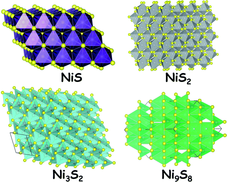
Sulphides of nickel are some of the most studied forms of nickel chalcogenides for electrocatalytic hydrogen generation. Their reasonable stability (but still poor) under reductive applied potential in both acid and alkali makes them attractive electrocatalysts for the HER. In general,39,40 sulphides of nickel are stoichiometric such as NiS. Sometimes, they do form non-stoichiometric polymorphs including Ni9S8 and Ni3S2. Apart from these sulphides, there is another nickel sulphide (NiS2) which contains a disulphide dianion and forms pyrite-type crystals. The naturally occurring mineral millerite (NiS) and the stoichiometric NiS are odourless. Interestingly, the nickel sulphides are insoluble in water which makes them a suitable and stable candidate for neutral, near-neutral and alkaline water splitting electrocatalysis. However, these materials when exposed to strong nitric acid medium dissolve in no time. This pitfall with these electrocatalysts is overcome by maintaining a reductive atmosphere while electrocatalyzing the HER in acid. The most common polymorph of nickel sulphide is NiS (millerite) which has a trigonal crystal system with the space group R3m. Fig. 1 shows the crystal structures of NiS, NiS2, Ni3S2 and Ni9S8. The stability of these materials is quite high under extremely alkaline conditions as there is a spontaneous formation of an oxide/hydroxide layer over the surface of the sulphides. Hence, these materials act as good HER electrocatalysts as well as good OER precatalysts.12 The OER activity under alkaline conditions is highly enhanced when these sulphides are doped with ions of Fe and Co.2.2. Nickel selenides39
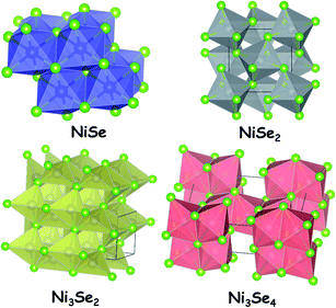
Nickel selenides are the second ones of nickel chalcogenides that are vastly studied for electrocatalytic water splitting. There are four different types of nickel selenides which are Ni1−xSe (0 < x < 0.15), NiSe2, Ni3Se4 and Ni2Se3.39 Unlike the simple stoichiometric nickel sulphide, the most common nickel selenide (Ni1−xSe (0 < x < 0.15)) is usually non-stoichiometric. All nickel selenides in general are black in colour and do not get dissolved in water. The insolubility of nickel selenides in water is one of the crucial parameters that make them perfect for electrocatalytic water splitting application like nickel sulphides. Not only water, there is no other solvent which could dissolve nickel selenides. However, like nickel sulphides, these selenides of nickel tend to dissolve readily in highly oxidizing acids such as HNO3.As far as the stability is concerned, they are perfectly stable in neutral water and neutral water solutions of other electrolytes. This is an advantageous factor when these materials are deployed for electrochemical water splitting in neutral and near-neutral media. However, the stability of nickel selenides in acid is poor particularly under anodic conditions in which these materials get dissolved in no time within the electrolyte solution. In contrast, they are quite stable under cathodic conditions. In terms of this property, nickel selenides resemble nickel sulphides. Under alkaline conditions, these materials also form surface layers of oxides/hydroxides of nickel which makes them a better catalyst for the OER. In general, all nickel selenides are semiconducting in nature. Hence, their electrocatalytic activity is greatly influenced by the support materials used as substrate electrodes. Similarly, the electrocatalytic activities of nickel selenides are highly sensitive to the local surface electronic structure. By tuning this via doping with other metal ions and anions, their activity can be regulated in a way one wants it to be in electrocatalytic water splitting. Fig. 2 shows the crystal structures of NiSe, NiSe2 (pyrite type), Ni3Se2 and Ni3Se4. All these polymorphs have been studied with different morphologies and with varying substrate materials which are discussed in the upcoming sections of this review. Depending on the medium of electrocatalysis and the nature of the substrate electrode, the same polymorph was found to show different electrocatalytic activity trends towards the HER.
2.3. Nickel tellurides39
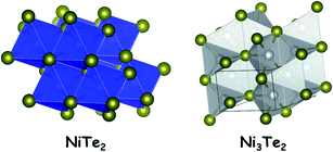
The tellurides of nickel are not the thoroughly studied ones in electrocatalytic water splitting when compared to the sulphides and selenides. Unlike the sulphides and selenides of nickel, nickel tellurides have the advantage of possessing a relatively more metallic anion in their crystal structure which provides additional electronic conductivity to the bulk material. Nickel tellurides have been reported to exist in three different stoichiometric forms such as NiTe, NiTe2 and Ni3Te2. All of them are non-stoichiometric in nature.39Also, they are equally conductive and provide an excellent catalytic surface for HER electrocatalysis. Other properties of nickel tellurides are common to the sulphides and the selenides. The stability of nickel telluride electrocatalysts in the HER is better than that of both nickel sulphides and nickel selenides. This can be attributed to the improved reluctance towards surface reconstruction when exposed to acidic and alkaline environments under reductive conditions. However, the activity is relatively poor which is attributed to the decreased electronegativity of the telluride anion which poorly attracts protons when compared to sulphides and selenides. On the other hand, the same reluctance towards surface reconstruction of nickel tellurides is one of the reasons for their relatively poor OER performance as precatalysts under alkaline conditions. Fig. 3 shows the crystal structures of NiTe2 and Ni3Te2.
Major differences in the structural and electronic features of sulphides, selenides, and tellurides of nickel lie in Ni–X (X = S, Se, and Te) bond length, band gap and energetics of X–H (X= S, Se, and Te) bonds39 which have significant roles in their HER activity trend. Specifically, the average range of the Ni–S bond length is from 2.02 to 2.13 Å while the same for Ni–Se and Ni–Te bonds are 2.338 to 2.442 Å and 2.492 to 2.667 Å, respectively. This is in accordance with the periodic property expected from the position of S, Se, and Te in group VI. This difference in bond length is crucial in determining the HER activity as these anions usually begin H2 evolution by trapping H+. Similarly, the band gap of these semi-conducting chalcogenides also plays important roles in the HER. Nickel sulphides and selenides have band gaps in the range of 1.92–2.41 eV and 1.95–2.05 eV, respectively. Interestingly, Ni–Te is a zero band gap semiconductor which is mainly due to the Te being more metallic in character rather than a metalloid. However, Ni–Te possesses similar physical and chemical properties to other semiconducting nickel chalcogenides. These observations clearly imply that Ni–Te has HER favouring zero band gap. Nevertheless, it must be concluded here that the zero band gap nature of Ni–Te makes it better in the HER. In fact, it is the energetics of X–H (X= S, Se, and Te) bonds that tend to control the HER activity more than the Ni–X (X = S, Se, and Te) bond length and band gap. The energies of S–H, Se–H, and Te–H bonds are 363, 273, and 238 kJ mol−1, respectively. For a better HER performance, the energy of X–H (X = S, Se, and Te) bonds must neither be too strong (as this would poison the catalyst surface after forming the X–H bond) nor too weak (as this would make initial adsorption of protons harder). In that viewpoint, the Se–H bond has the optimum energy.
Though the sulphides, selenides and tellurides of nickel are frequently studied for electrocatalytic water splitting, there are only a few reports that intended to explain the role of electronegativity of these anions in HER electrocatalysis and their influence in activating the OER electrocatalysis as a synergistic support. The upcoming sections of this review are dedicated to discussing the developments in utilizing these nickel chalcogenides in electrocatalytic hydrogen evolution of water splitting.
3. What to anticipate while screening electrocatalysts
Prior to discussing the chronological developments of nickel chalcogenide electrocatalysts in hydrogen evolution, it would be highly useful if the screening parameters and the highlights on what should one anticipate while screening OER and HER electrocatalysts are briefed. There are many research studies, reviews and perspectives on the best practices of screening electrocatalysts for electrochemical water splitting.12,41–43 Hence, this section is limited to just highlighting what one should anticipate from the electrocatalyst that is under screening. This will also enable the reader to understand the forthcoming discussion of this review.3.1. Low overpotential
Overpotential is nothing but the additional potential an electrode (catalyst modified) requires to perform an electrochemical charge transfer reaction of interest from its standard redox potential. In electrochemical water splitting, anodic and cathodic charge transfer reactions are the OER and HER, respectively, which are theorized to occur at 1.229 and 0.0 V vs. the reversible hydrogen electrode (RHE). However, due to various kinetics and thermodynamics reasons, these reactions always occur at potentials that are far from their equilibrium potential. Hence, it is always better to have the lowest possible overpotential for any given electrocatalyst. One should also be vigilant in perceiving the overpotential data in the literature as different normalization methods will result in different values. Because, for the same electrocatalyst, the geometrical surface area, electrochemical surface area (ECSA) and specific surface area may differ drastically. As a consequence of which the calculated overpotential would also vary. Apart from this, it is also common to come across a few catalysts for which the mass activity is preferred for calculating the overpotential. There are a few potential reviews and perspectives which elaborate the difference among these normalization techniques that would give a deep understanding of calculating overpotential from current densities that are normalized by different methods.12,41,43 In general, the performance of an electrode is primarily assessed by calculating its overpotential at 10 mA cm−2. Nonetheless, this overpotential at 10 mA cm−2 will vary with varying catalyst loading, normalization method and percentage of iR drop compensation.42 The effect of different percentages of iR drop compensation on the overpotential was exclusively discussed in our earlier perspective.413.2. Low Tafel slope and high exchange current density
Tafel analysis is an important one in any electrocatalytic study which sheds light on the mechanism of the rate determining step (RDS) of the HER.44,45 With this analysis, one would get two important activity markers of an electrocatalyst, which are Tafel slope and exchange current density. Eqn (1) is the famous Tafel equation which is just a simplified form of Butler–Volmer equation at the high overpotential region where the current–potential relationship is no longer linear.| η = A × log(j/j0) | (5) |
In the above equation, η represents the overpotential, j represents the current density, j0 represents the exchange current density and A represents the Tafel slope. The Tafel slope can further be expanded as given in eqn (2).
A = 2.303![[thin space (1/6-em)]](https://www.rsc.org/images/entities/char_2009.gif) RT/αnF RT/αnF | (6) |
In this equation, R represents the gas constant, T represents the absolute temperature in K, α represents the charge transfer coefficient, n represents the number of electrons transferred in the rate-determining step and F represents the Faraday constant (96![[thin space (1/6-em)]](https://www.rsc.org/images/entities/char_2009.gif) 485 C mol−1). It has already been stated that the best catalyst should always possess a lower overpotential. According to eqn (5) and (6), the electrocatalyst under study must have a lower Tafel slope and high charge transfer coefficient to have a lower overpotential and the kinetics information that we get here is solely of the RDS and not of the whole HER. Similarly, exchange current density (j0) is the second activity marker that one could obtain from Tafel analysis. It is defined as the rate of oxidation and reduction reactions of the electroactive species under study at zero overpotential (i.e., at equilibrium potential). Hence, it is always advantageous to have an electrocatalyst which performs the desired electrochemical reaction at equilibrium potential to have a lower overpotential. Methods of obtaining Tafel plots and ways of interpreting activity markers from Tafel plots were elaborated in our earlier perspective.41
485 C mol−1). It has already been stated that the best catalyst should always possess a lower overpotential. According to eqn (5) and (6), the electrocatalyst under study must have a lower Tafel slope and high charge transfer coefficient to have a lower overpotential and the kinetics information that we get here is solely of the RDS and not of the whole HER. Similarly, exchange current density (j0) is the second activity marker that one could obtain from Tafel analysis. It is defined as the rate of oxidation and reduction reactions of the electroactive species under study at zero overpotential (i.e., at equilibrium potential). Hence, it is always advantageous to have an electrocatalyst which performs the desired electrochemical reaction at equilibrium potential to have a lower overpotential. Methods of obtaining Tafel plots and ways of interpreting activity markers from Tafel plots were elaborated in our earlier perspective.41
3.3. High faradaic efficiency
Electrochemical water splitting, in particular the OER, can be accompanied by various other reactions such as superoxide formation, hydrogen peroxide formation and ozone formation at high overpotential regions. In addition to this, there is always oxidation and reduction of catalytic species when a catalyst performs the OER. All these factors together result in a high probability of wasting the applied energy. Hence, to ensure that the catalyst under study is selective to the desired water splitting reaction, faradaic efficiency (FE) measurements are generally made. Ways of obtaining FE can be found in many earlier reviews and perspectives.12,41 As FE reflects the selectivity of an electrocatalyst, it must be as high as 100% for both the HER and OER. Unfortunately, the OER is not always very selective and does not have 100% FE in most of the cases. However, there are some exceptions.3.4. Good stability
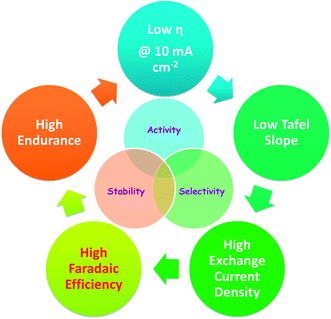
Apart from activity and selectivity, stability of an electrocatalyst is an essential criterion that promotes its use in commercial water electrolysers. An electrocatalyst of poor stability despite having high activity and selectivity is not considered as a good one. Hence, an electrocatalyst must possess good stability along with activity and selectivity. In electrochemical water splitting, stability is tested by rapid CV cycling for several hundreds to a few thousand cycles. A higher number of CV cycles is usually reported for the HER which is the relatively facile half-cell reaction of electrochemical water splitting. At the end of this cycling study, the change in overpotential at a fixed current density is measured and reported as the marker of stability of the catalyst under study. An increase by ∼30 mV in overpotential is generally accepted for a good catalyst. Similarly, the endurance under static (potential/galvanic) mode is also tested for several hours to a few days. At the end of this endurance test, the percentage degradation in activity is reported as the stability marker of the catalyst. Any electrocatalyst that shows activity degradation no more than 5% is generally accepted as a good one. Scheme 1 depicts the overall desired characteristics discussed above for a given electrocatalyst. Other than the above listed characteristics, a given electrocatalyst must also possess a large ECSA to accommodate as many electroactive species as possible (i.e., water in this case) at the electrochemical interface and low charge transfer resistance under catalytic turnover conditions. These two factors are behind observing a lower overpotential, lower Tafel slope and high exchange current density.4. Nickel chalcogenides in electrocatalytic water splitting
From the origin of electrocatalytic water splitting for hydrogen production with non-precious electrocatalysts, nickel based electrocatalysts are being intensively investigated. In this section of the review, the developments in using nickel chalcogenides are discussed in the order of sulphides, selenides and tellurides. Meanwhile, the challenges and opportunities for furthering this field with these electrocatalysts are also simultaneously elaborated.4.1. Early studies
Electrochemical hydrogen evolution with nickel sulphides was known even in the 70s and 80s of the 20th century. Vandenborre et al.46 were the first ones to show the transient behaviour of a NiS cathode in an alkaline medium (1 N NaOH). Such a transient behaviour of the electrodeposited NiS cathode was attributed to the oxidation of strongly bonded and weakly adsorbed hydrogen at the surface during anodic scan of potential. Later, Han et al.47 deposited NiS electrochemically with a modified procedure in which they used thiourea as the source of sulphur. This method led them to fabricate an amorphous NiS film which showed lower activation energy for the HER than many other cathodes studied along. The same group of researchers extended this study soon after their first study by incorporating Co into the NiS cathode.48 This time, the amorphous Ni–S–Co alloy obtained through a similar electrodeposition method with added CoCl2 showed better HER activity in alkali. These are the few significant studies which employed NiS as a catalytic cathode for the HER in alkali in earlier days. In those periods, other chalcogenides such as selenides and tellurides were yet to be examined for electrocatalytic water splitting studies.4.2. Sulphides of nickel in electrochemical hydrogen evolution
As indicated earlier nickel sulphides are some of the extensively studied HER electrocatalysts in the literature. Though a variety of nickel sulphides were known to catalyse the HER decades earlier, significant improvement in their activity was brought about in recent years only. A notable study of fabricating NiSx thin films through a gas phase deposition of a Ni precursor using bis(N,N′-di-tert-butylacetamidinato)nickel(II)(Ni(amd)2) vapor and hydrogen sulphide was shown by Çimen et al.49 When the fabricated (optimized) thin film of NiSx was screened for the HER in acid and PBS, it demanded 440 and 576 mV, respectively, to deliver the benchmarking current density of 10 mA cm−2. These overpotential values were still higher than the ones reported earlier which could be attributed to the lower catalyst loading achieved with this fabrication method. Around the same time, Lin et al.50 proposed an intriguing way of increasing the number of electrochemically accessible sites in Ni3S2 by making a composite with multi-walled carbon nanotubes (MWCNTs). This particular electrode (Ni3S2/CNT) was found to have just one-third of the activation energy required by the pristine Ni3S2 which implied that there was a synergism between Ni3S2 and CNTs for the HER in an alkaline medium. Then arrived the revolutionary 3D electrodes of nickel sulphides on Ni foam and carbon cloth (CC) electrodes. These 3D electrodes had both highly active surface area and capability to get loaded with greater quantities of catalysts. Such advantageous features of these 3D electrodes brought down the overpotential values lower than never before. Significant studies that utilized these 3D substrate electrodes are as follows. Zhu et al.51 sulphurized the Ni foam electrode directly by taking the S powder at high temperature in an inert atmosphere which resulted in the formation of NiS microspheres with high loading. As a consequence of this high catalyst loading, this catalytic HER electrode demanded a relatively lower overpotential of 158 mV for delivering 20 mA cm−2 in 0.1 M KOH. In a closely resembling study, Ouyang et al.52 made a Ni3S2/Ni foam electrode by a two-step process in which the acid treated Ni foam was thermally oxidized at the surface by annealing first. Then, the same was hydrothermally treated with thiourea to form Ni3S2via an anion exchange reaction. However, the required HER overpotential at 10 mA cm−2 was higher (200 mV) than that of the NiS microspheres on Ni foam reported by Zhu et al.51 This difference could either be due to the stoichiometric difference (i.e., Ni![[thin space (1/6-em)]](https://www.rsc.org/images/entities/char_2009.gif) :
:![[thin space (1/6-em)]](https://www.rsc.org/images/entities/char_2009.gif) S ratio) or loading differences. Tang et al.53 came up with another polymorph of nickel sulphide, the pyrite type NiS2. This pyrite-type NiS2 was grown as nanoarrays on a CC electrode following a two-step process in which Ni(OH)2 nanoarrays were first hydrothermally fabricated on the CC which was then subjected to sulphurization with sulphur. This electrode also showed good HER electrocatalytic activity demanding 243 mV at 10 mA cm−2. This overpotential value is higher than that of both NiS/Ni foam reported by Zhu et al.51 and Ni3S2/Ni foam reported by Ouyang et al.52 The difference in activity with this electrode could be attributed to the same factors discussed above. In addition, the relatively lower degree of 3D structure with the CC could also be a reason for not observing closer overpotentials which might have not let it accommodate as much nickel sulphide as Ni foam did. Apart from these studies, Qin et al.54 studied the HER electrocatalytic activity of NiS/Ni3S4 by changing the NiS
S ratio) or loading differences. Tang et al.53 came up with another polymorph of nickel sulphide, the pyrite type NiS2. This pyrite-type NiS2 was grown as nanoarrays on a CC electrode following a two-step process in which Ni(OH)2 nanoarrays were first hydrothermally fabricated on the CC which was then subjected to sulphurization with sulphur. This electrode also showed good HER electrocatalytic activity demanding 243 mV at 10 mA cm−2. This overpotential value is higher than that of both NiS/Ni foam reported by Zhu et al.51 and Ni3S2/Ni foam reported by Ouyang et al.52 The difference in activity with this electrode could be attributed to the same factors discussed above. In addition, the relatively lower degree of 3D structure with the CC could also be a reason for not observing closer overpotentials which might have not let it accommodate as much nickel sulphide as Ni foam did. Apart from these studies, Qin et al.54 studied the HER electrocatalytic activity of NiS/Ni3S4 by changing the NiS![[thin space (1/6-em)]](https://www.rsc.org/images/entities/char_2009.gif) :
:![[thin space (1/6-em)]](https://www.rsc.org/images/entities/char_2009.gif) Ni3S4 molar ratio. This study revealed that the best composition for observing better HER activity was 1
Ni3S4 molar ratio. This study revealed that the best composition for observing better HER activity was 1![[thin space (1/6-em)]](https://www.rsc.org/images/entities/char_2009.gif) :
:![[thin space (1/6-em)]](https://www.rsc.org/images/entities/char_2009.gif) 1. The above discussed studies were mainly focused on the optimization of parameters to achieve the best HER activity with a single polymorph of nickel sulphide. No attempt was made to reveal the effect of stoichiometric differences of nickel sulphides on the HER activity until the study of Jiang et al.55 In this case study, they prepared a series of nickel sulphide nanoparticles (NPs) with varying stoichiometries such as NiS, NiS2 and Ni3S2. The order of HER activity of these stoichiometrically different nickel sulphide NPs was found to be Ni3S2 > NiS2 > NiS. The superior activity of Ni3S2 was attributed to the high ECSA and electrical conductivity of the same. The results of this study are contradicting with the results of the earlier studies discussed above. This contradiction might be a consequence of the different morphologies, loadings, electrochemical conditions and substrate electrodes used in those studies. This led us to conclude here that as far as monometallic nickel sulphides for the HER are concerned, their activity trend is still elusive and systematic studies are yet to be conducted.
1. The above discussed studies were mainly focused on the optimization of parameters to achieve the best HER activity with a single polymorph of nickel sulphide. No attempt was made to reveal the effect of stoichiometric differences of nickel sulphides on the HER activity until the study of Jiang et al.55 In this case study, they prepared a series of nickel sulphide nanoparticles (NPs) with varying stoichiometries such as NiS, NiS2 and Ni3S2. The order of HER activity of these stoichiometrically different nickel sulphide NPs was found to be Ni3S2 > NiS2 > NiS. The superior activity of Ni3S2 was attributed to the high ECSA and electrical conductivity of the same. The results of this study are contradicting with the results of the earlier studies discussed above. This contradiction might be a consequence of the different morphologies, loadings, electrochemical conditions and substrate electrodes used in those studies. This led us to conclude here that as far as monometallic nickel sulphides for the HER are concerned, their activity trend is still elusive and systematic studies are yet to be conducted.
Apart from being reported as efficient monometallic HER electrocatalysts, nickel sulphides were often combined with other metals such as Mo, Co, Fe, V, Cu, W and even Pt to boost their HER electrocatalytic activity. In some cases, Ni was used to boost the HER electrocatalytic activity of other known catalysts such as MoSx, CoSx and WSx. Some of such important studies and their significant results are discussed below. MoSx are well-known for their HER electrocatalytic properties in both acid and alkali.33,56–58 Their activity was further advanced by incorporating Ni into their lattices.
First such example was shown by Yu et al.59 who prepared Ni–Co–MoS2 nanoboxes via a two-step process in which first the nanoboxes of the Ni–Co Prussian blue analogue (PBA) were precipitated and treated solvothermally with ammonium thiomolybdate at high temperature to form Ni–Co–MoS2 hollow nanoboxes. This catalyst when screened for the HER in comparison with MoS2 delivered better activity by requiring 30 mV less than that of MoS2 to drive 10 mA cm−2 in 0.5 M H2SO4. Such an enhanced activity of Ni–Co–MoS2 hollow nanoboxes was attributed to high ECSA, better charge transfer and improved kinetics. Another instance where such enhanced activity of MoS2 in the HER observed was with the MoS2|NiS|MoO3/Ti foil. Wang et al.60 prepared this electrode through a two-step process in which a NiMoO4 array was made first by hydrothermal treatment of polished Ti foil with Ni and Mo precursors at high temperature. This NiMoO4 array was then sulphurized with sublimed S powder at 500 °C. This catalytic electrode has shown an all-time record in HER overpotential requiring just 90 mV to reach 10 mA cm−2 that too under alkaline conditions (Fig. 4a–d). Another metal sulphide that benefited from the inclusion of Ni is CoSx. It was Sivanantham et al.61 who first fabricated a Ni–Co carbonate precursor on a Ni foam electrode using urea under hydrothermal conditions followed by sulphurization of the same using Na2S solution under hydrothermal conditions at a relatively higher temperature. This catalytic electrode has shown better HER activity than NiCo2S4, NiCo2O4, Ni3S2 and Ni foam under identical experimental conditions requiring low overpotential. In another attempt to prepare such a Ni and Co containing sulphide HER electrode using Ni foam, Ma et al.62 electrodeposited Co onto the surface of Ni foam from a solution mixture of cobaltous chloride, cobaltous sulphide and boric acid which was then treated with thiourea hydrothermally resulting in the formation of a NiS–CoS/Ni foam catalytic electrode. This 3D electrode needed just 90 and 105 mV for delivering 10 mA cm−2 in acid and alkali, respectively. Liu et al.63 later came up with a heterostructured NiCo2S4@NiFe LDH/Ni foam electrode which was fabricated by a multi-step hydrothermal process. This heterostructured electrode showed appreciable HER electrocatalytic activity demanding 200 mV at 10 mA cm−2. Apart from Co and Mo, Fe was used to make a binary iron–nickel-sulphide (INS) for HER application through topotactic conversion of Fe–Ni LDH by Long et al.64 This catalyst showed better activity than pristine β-NiS in 0.5 M H2SO4 requiring 105 mV at 10 mA cm−2.
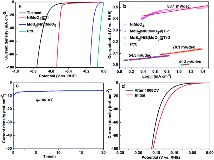 | ||
| Fig. 4 (a) HER LSVs of MoS2|NiS|MoO3/Ti foil in comparison with other studied electrodes in 1 M KOH. (b) Corresponding Tafel plots. (c) CA response of MoS2|NiS|MoO3/Ti foil for more than 20 h. (d) HER LSVs of MoS2|NiS|MoO3/Ti foil before and after 1000 CV cycles. Reproduced with permission from ref. 60 (Copyright 2017 American Chemical Society). | ||
This enhancement was attributed to the higher relative ECSA determined from the double layer capacitance of β-INS (Fig. 5a–d). Recently, Feng et al.65 in their study found that when Ni3S2 sheets were decorated with Cu nanodots, they tend to double their HER activity. Such a Cu nanodot decorated Ni3S2 electrode necessitated 128 mV to reach 10 mA cm−2 while having a relatively smaller Tafel slope of 76.2 mV dec−1 in 1 M KOH. Around the same time, Qu et al.66 reported the HER enhancing effect of a V-dopant when it is doped with Ni3S2. This catalyst was fabricated on a Ni foam 3D electrode following a simple single-step hydrothermal treatment of sodium orthovanadate, thioacetamide and pre-treated Ni foam pieces at high temperature.
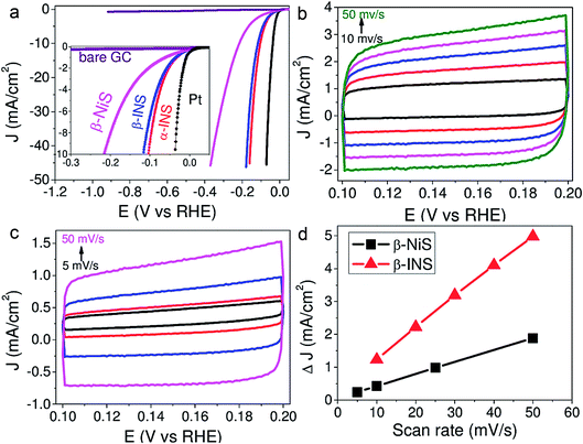 | ||
| Fig. 5 (a) HER LSVs of β-NiS, β-INS, α-INS and Pt showing the superiority of INS electrodes over NiS. (b and c) CVs recorded at different scan rates to calculate the relative ECSA of β-NiS and β-INS, respectively. (d) The plot of scan rate against the difference in the double layer charging current density of the same showing higher relative ECSA for β-INS. Reproduced with permission from ref. 64 (Copyright 2015 American Chemical Society). | ||
This catalytic HER electrode broke the earlier record of 90 mV at 10 mA cm−2 necessitated by MoS2|NiS|MoO3/Ti foil60 by requiring just 68 mV for achieving the same current density under identical alkaline conditions. Wang et al.67 reported a systematic study of converting a compositionally segregated Pt–Ni nanowire electrode into a Pt–Ni/NiS heterostructured electrode for HER application in alkali. In this study, the Pt![[thin space (1/6-em)]](https://www.rsc.org/images/entities/char_2009.gif) :
:![[thin space (1/6-em)]](https://www.rsc.org/images/entities/char_2009.gif) Ni ratio was systematically varied and the effect of forming a heterostructure with NiS through a gas phase sulphurization in the HER was studied. Among the studied compositions, the best HER activity was observed with a Pt3Ni2 NW–NiS heterostructured catalyst (Fig. 6a and b). Key activity markers such as overpotential at 10 mA cm−2, Tafel slope and loading of the above discussed reports are summarized in Table 2. The results of the above discussed studies have shown us that the field of utilizing nickel sulphides as HER electrocatalysts has significantly grown in recent years during which much notable advancements such as the use of 3D and flexible electrodes for the in situ fabrication of nickel sulphides and alloying/doping with another metal were made.
Ni ratio was systematically varied and the effect of forming a heterostructure with NiS through a gas phase sulphurization in the HER was studied. Among the studied compositions, the best HER activity was observed with a Pt3Ni2 NW–NiS heterostructured catalyst (Fig. 6a and b). Key activity markers such as overpotential at 10 mA cm−2, Tafel slope and loading of the above discussed reports are summarized in Table 2. The results of the above discussed studies have shown us that the field of utilizing nickel sulphides as HER electrocatalysts has significantly grown in recent years during which much notable advancements such as the use of 3D and flexible electrodes for the in situ fabrication of nickel sulphides and alloying/doping with another metal were made.
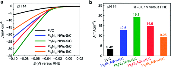 | ||
| Fig. 6 (a) HER LSVs of compositionally segregated Pt–Ni NWs/NiS heterostructured electrodes in alkali (pH 14) recorded at 10 mV s−1 with 1600 rpm and presented without iR drop compensation. (b) Histogram showing the current density of the studied catalysts at −0.07 V vs. RHE. Adapted from ref. 67. | ||
| Catalyst | Medium | Loading/mg cm−2 | Overpotentiala/mA | Tafel slope/mV dec−1 | Reference |
|---|---|---|---|---|---|
| a Overpotentials are calculated at 10 mA cm−2 unless otherwise mentioned. NA represents that the respective information was not available in the cited report. | |||||
| a-Fe–Ni–S | 0.5 M H2SO4 | NA | 105 | 40 | Long et al.64 |
| Ni–Co–MoS2 nanoboxes | 0.5 M H2SO4 | NA | 185 | 51 | Yu et al.59 |
| NiSx film | 0.5 M H2SO4 | 0.004 | 440 | 62 | Çimen et al.49 |
| Ni/Co–S | 0.5 M H2SO4 | NA | 85 | 61 | Ma et al.62 |
| MoS2|NiS\MoO3 | 1 M KOH | 2 | 91 | 54.5 | Wang et al.60 |
| Cu nanodots@Ni3S2 | 1 M KOH | 0.52 | 128 | 76.2 | Feng et al.65 |
| V-doped Ni3S2 | 1 M KOH | NA | 68 | 112 | Qu et al.66 |
| Ni3S2 nanorods | 1 M KOH | NA | 200 | 107 | Ouyang et al.52 |
| Ni3S2@CNT | 1 M KOH | 0.6 | 340 | 102 | Lin et al.50 |
| NiCo2S4@Ni foam | 1 M KOH | NA | 210 | 58.9 | Sivanantham et al.61 |
| NiCo2S2@NiFe LDH | 1 M KOH | NA | 200 | 101.1 | Liu et al.63 |
| NiS@Ni foam | 1 M KOH | 158 @ 20 mA cm−2 | 83 | Zhu et al.51 | |
| NiS | 1 M KOH | 0.283 | 474 | 124 | Jiang et al.55 |
| NiS2 | 1 M KOH | 0.283 | 454 | 128 | Jiang et al.55 |
| Ni3S2 | 1 M KOH | 0.283 | 335 | 97 | Jiang et al.55 |
| NiS2@CC | 1 M KOH | 4.1 | 149 | 69 | Tang et al.53 |
| Ni/Co–S | 1 M KOH | NA | 102 | 92 | Ma et al.62 |
| NiSx film | PBS | 0.004 | 576 | 123 | Çimen et al.49 |
These advancements have certainly improved the electrocatalytic performance of nickel sulphides in the HER under both acidic and alkaline conditions. However, the major issue, that is, poor electrochemical stability upon prolonged use has not been addressed yet. Similarly, though the above discussed advancements resulted in improvement of the performance, the HER activity of these advanced catalysts is not still comparable to that of pnictides and noble metals. Hence, the opportunities available for furthering this field are as follows: (i) exchanging anions with high corrosion stability, (ii) incorporating other d and p block elements, (iii) improving the bulk conductivity of semiconducting nickel sulphides, and (iii) creating defect sites for enhanced HER activity. Stating these ways, we hope that further advancements are not so far in future.
4.3. Selenides of nickel in electrochemical hydrogen evolution
Nickel selenides are another class of nickel chalcogenide based HER electrocatalysts that have been extensively investigated in recent years. As described earlier, almost all nickel selenides are non-stoichiometric in nature and always form a defect rich structure in both bulk and nano dimensions.39 In addition, they also have better bulk electrical conductivity than nickel sulphides as a result of having a relatively more metallic anion (selenide). Both these advantages together fetch better HER electrocatalytic activity for nickel selenides.Like nickel sulphides, nickel selenides have been studied in mono-metallic form, with other metal dopants and synergistically HER enhancing support materials, which often served as substrate electrodes in most of the studies. In the impending discussion, mono-metallic nickel selenides are discussed prior to bi- and multi-metallic versions of the same. In the monometallic version of nickel selenides, NiSe/Ni0.85Se is the most studied polymorph for HER electrocatalysis. Gao et al.68 first showed the HER electrocatalytic activity of urchin-like NiSe nanofiber assemblies in 0.5 M sulphuric acid with a lower Tafel slope of 64 mV dec−1. This catalyst's performance was comparable to that of the then highly active non-precious metal chalcogenide MoS2. Later, Tang et al.69 grew NiSe nanowires on a Ni foam substrate electrode through hydrothermal treatment of Ni foam and NaHSe obtained by dissolving Se in NaBH4. This catalytic electrode required an overpotential of 96 mV to reach 10 mA cm−2 while showing better stability in both cycling and chronoamperometry analysis (Fig. 7a–d). However, the same electrode has shown poor kinetics demanding a relatively higher Tafel slope of 120 mV dec−1 which is attributed to the highly proton deficient alkaline environment (1 M KOH). Soon after this, Wang et al.70 proposed a way of electrodepositing NiSe on the composite film of reduced graphene oxide-polyimide/CNTs. Though this electrodeposited NiSe exhibited promising kinetics having a lower Tafel slope (61 mV dec−1), it required a relatively higher overpotential (270 mV) due to lower catalyst loading compared to that of NiSe/NF reported by Tang et al.69 earlier. This implies that for achieving better kinetics while securing high activity, both catalyst loading and film thickness should be optimized. An interesting comparison of the HER activities of nanocrystalline Ni0.85Se prepared by the dimethyl formamide (DMF)-solvothermal method and the hydrothermal method was made by Yu et al.71 In this study, it was shown that the one prepared by the DMF-solvothermal method performed better than the other one, showing better kinetics in terms of a typical Tafel slope of 49.3 mV dec−1. However, this study did not disclose why such a difference is observed in the HER activities of these catalysts prepared in two different ways.
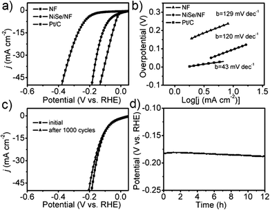 | ||
| Fig. 7 (a) HER LSVs of NiSe/NF, NF and Pt/C in 1 M KOH. (b) Tafel slopes of the same. (c) LSVs of NiSe/NF before and after 1000 cycles. (d) CA response of the same in 1 M KOH (NF denotes Ni foam). Reproduced with permission from ref. 69 (Copyright 2105 Wiley Publications). | ||
Very recently, Wu et al.72 reported a facile way of fabricating ultrathin 2D layered NiSe nanosheets on Ni foam through a two-step process. In this study, the substrate Ni foam was acid-etched to facilitate the hydrolysis of nickel as Ni2+ and re-deposition of the same as Ni(OH)2 on its surface first. Then, this was selenized topotactically without destructing the microstructural properties. Because of such non-destructive selenization, the resultant catalytic electrode retained high ECSA which consequently led to high activity. In particular, when this catalytic electrode was screened for the HER in 1 M NaOH, it required 170 mV to achieve 10 mA cm−2. Around the same time, Bhat and Nagaraja73 compared the HER activity of NiSe2/Ni foam prepared by a two-step hydrothermal and anion exchange process and NiSe/Ni foam prepared by direct hydrothermal treatment of the same with Se. Activity markers of this study showed that the NiSe2/Ni foam performed better in HER electrocatalysis under identical electrochemical conditions. However, these results cannot be taken directly for comparing the HER activity of NiSe and NiSe2 as there are chances for huge variation in the loaded mass of the catalyst due to the difference in total reaction times. Following this study, the effect of a NiSe–Ni0.85Se heterostructure on the HER electrocatalytic activity was recently shown by Chen et al.74 For making such heterostructures, NiO nanostructures were first grown on carbon paper which was then selenized through the standard hydrothermal treatment using NaHSe solution (Fig. 8a–f). The thus fabricated heterostructure delivered better HER activity in alkali than others as shown in Fig. 8e while having a lower Tafel slope of 74 mV dec−1. The reason behind such an activation with this heterostructure was found to be its moderate –OH adsorption free energy which is much closer to zero when compared to others for the reduction of protons to hydrogen molecules.
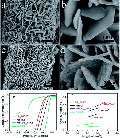 | ||
| Fig. 8 (a and b) SEM image of NiO/CP. (c and d) SEM image of NiSe–Ni0.85Se/CP. (e and f) HER LSVs and the Tafel slope of NiSe–Ni0.85Se/CP in comparison with other studied catalysts in 1 M KOH. Reproduced with permission from ref. 74 (Copyright 2018 Wiley Publications). | ||
Nickel diselenide (NiSe2) is relatively less explored in the HER when compared to the simple NiSe which is mainly due to the difficulties associated with its synthesis. However, there has been increasing interest in this polymorph of nickel selenide recently. Pu et al.75 were the first to electrodeposit this polymorph of nickel selenide on a Ti substrate. This NiSe2/Ti electrode when tested for the HER in 1 M KOH necessitated just 96 mV for achieving the benchmarking current density with a smaller Tafel slope of 82 mV dec−1. Soon after this study, Wang et al.76 achieved the lowest ever Tafel slope of 32 mV dec−1 in sulphuric acid electrolyte with NiSe2 nanosheet arrays.
This was the first study to show that the proton adsorption free energy was much lower on Se sites (0.13 eV) than on Ni sites (0.87 eV) which indeed explained the better HER activity of nickel selenides and selenized nickel electrodes than Ni metal. Later, Swesi et al.77 showed that texturing a NiSe2 film could improve it's HER activity under alkaline conditions by lowering the overpotential at 10 mA cm−2. However, such a textured film of NiSe2 also showed poor kinetics in terms of having a high Tafel slope (107 mV dec−1).
Other than this, Li et al.78 showed an intriguing way of improving the stability of NiSe2 in HER electrocatalysis for more than 24 h by decorating it with NiO NPs. Though there have been several studies on the fabrication and evaluation of nickel selenide polymorphs recently, the primary way of selenization was either high temperature inert atmosphere annealing of the precursor material with Se or direct hydrothermal selenization of the precursor material with Se powder/NaHSe solution. Both methods required high temperature, pressure and an inert atmosphere for successful selenization. A significant advancement in the synthesis of nickel selenides on a Ni foam substrate was recently reported by our group.79 In this study, we have taken pieces of acid treated Ni foam and submerged them in a solution of NaHSe taken in a glass beaker. This solution was then irradiated with microwaves for just 3 min with a power of 300 W to initiate the nucleation of NixSey. The same was then subjected to aging at room temperature for 5 h (Scheme 2). By this way, a fine assembly of Ni3Se4 was obtained on the Ni foam electrode. When characterized for the HER in solutions of varying pH from 7 to 14.5, this catalytic electrode performed well delivering very high current densities with low overpotentials (206 mV @ −50 mA cm−2 in 3 M KOH and 282 mV @ −50 mA cm−2 in 1 M PBS) while securing better kinetics in terms of lower Tafel slopes (Fig. 9a–d). All the studies discussed above were carried out under different electrochemical conditions with different polymorphs of nickel selenide and with different catalyst loadings. Such differences witnessed in all these studies do not let us to come to a conclusion on the HER activity trend of stoichiometrically distinguishable nickel selenides. Hence, to shed light on the effect of stoichiometry and Ni![[thin space (1/6-em)]](https://www.rsc.org/images/entities/char_2009.gif) :
:![[thin space (1/6-em)]](https://www.rsc.org/images/entities/char_2009.gif) Se ratio, we have very recently carried out a systematic study synthesizing Ni0.85Se, Ni3Se4 and NiSe2 through a co-precipitation technique taking nickel chloride and NaHSe in desired molar ratio.80 The HER electrocatalytic activities of all three synthesized polymorphs of nickel selenides were characterized in sulphuric acid solution (pH 0). Fig. 10a shows the HER LSVs of Ni0.85Se, Ni3Se4 and NiSe2 with identical catalyst loading recorded at 5 mV s−1 without iR drop compensation. It can be witnessed from Fig. 10a that NiSe2 is the best among the three and delivered a very high current density and required the lowest Tafel slope (Fig. 10c and d). These results showed a direct dependence of the HER activity on the total selenium content.
Se ratio, we have very recently carried out a systematic study synthesizing Ni0.85Se, Ni3Se4 and NiSe2 through a co-precipitation technique taking nickel chloride and NaHSe in desired molar ratio.80 The HER electrocatalytic activities of all three synthesized polymorphs of nickel selenides were characterized in sulphuric acid solution (pH 0). Fig. 10a shows the HER LSVs of Ni0.85Se, Ni3Se4 and NiSe2 with identical catalyst loading recorded at 5 mV s−1 without iR drop compensation. It can be witnessed from Fig. 10a that NiSe2 is the best among the three and delivered a very high current density and required the lowest Tafel slope (Fig. 10c and d). These results showed a direct dependence of the HER activity on the total selenium content.
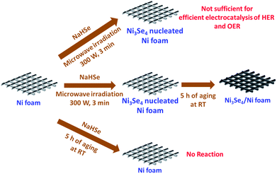 | ||
| Scheme 2 Synthesis of Ni3Se4 on Ni foam utilizing quick microwave irradiation and room temperature aging. Reproduced with permission from ref. 79 (Copyright 2017 American Chemical Society). | ||
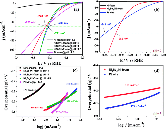 | ||
| Fig. 9 (a and b) HER LSVs of a Ni3Se4/Ni electrode in various alkaline pHs and in PBS, respectively. (c and d) The Tafel plots of the same under identical electrochemical conditions. Reproduced with permission from ref. 79 (Copyright 2017 American Chemical Society). | ||
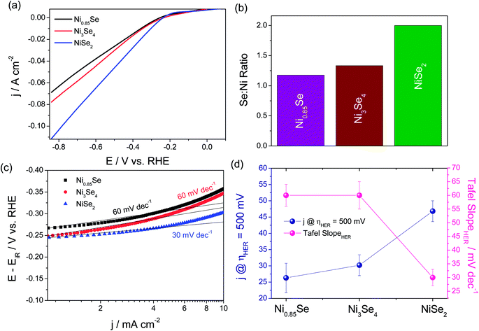 | ||
Fig. 10 (a) HER LSVs of Ni0.85Se, Ni3Se4 and NiSe2 with identical catalyst loading in 0.5 M H2SO4. (b) Histogram showing the Ni![[thin space (1/6-em)]](https://www.rsc.org/images/entities/char_2009.gif) : :![[thin space (1/6-em)]](https://www.rsc.org/images/entities/char_2009.gif) Se ratio. (c) The Tafel plots of Ni0.85Se, Ni3Se4 and NiSe2. (d) Comparison of activity and kinetics of Ni0.85Se, Ni3Se4 and NiSe2 in terms of HER current density at an overpotential of 500 mV and the Tafel slope. Reproduced with permission from ref. 80 (Copyright 2019 Elsevier Publications). Se ratio. (c) The Tafel plots of Ni0.85Se, Ni3Se4 and NiSe2. (d) Comparison of activity and kinetics of Ni0.85Se, Ni3Se4 and NiSe2 in terms of HER current density at an overpotential of 500 mV and the Tafel slope. Reproduced with permission from ref. 80 (Copyright 2019 Elsevier Publications). | ||
This could be due to the fact that the increased number of Se sites in NiSe2 might provide an easier reaction pathway for proton adsorption as a result of which high HER activity is witnessed. According to this study, we revealed that the HER activity trend of stoichiometrically different nickel selenides is in the order of NiSe2 > Ni3Se4 > Ni0.85Se. Though we have carried out a systematic study, it is still possible to witness ambiguities in the activity trend of nickel selenides as we did not account for actual ECSA available in Ni0.85Se, Ni3Se4 and NiSe2. Hence, we anticipate further systematic studies taking all significant factors into consideration in near future. So far, only mono-metallic nickel selenides and their HER activity trends were discussed. Apart from this, there are a few important studies performed with nickel selenides incorporating other metals such as Mo and Co which are discussed below. Zhou et al.81 revealed an interesting finding of enhanced HER kinetics while maintaining a decent overpotential at benchmarking current density. They revealed that making a heterostructure of NiSe with MoSe2 could lower the Tafel slope significantly to 56 mV dec−1 in an acidic medium. In a related study, Wang et al.82 fabricated a 3D heterostructure of MoSe2@Ni0.85Se through a hydrothermal method which upon HER characterization showed a smaller overpotential of 117 mV at 10 mA cm−2. This is one of the lowest overpotentials ever reported for the HER under alkaline conditions. These two studies showed the advantages of having such an all selenium heterostructure between Ni and Mo. However, there is no study on S and Se containing Ni–Mo heterostructures which possess the potential of having better activity towards the HER. On the other hand, Co did not form a heterostructure with nickel selenides. Instead, it resulted in a single phase material either as Ni0.33Co0.67Se2 or as Ni0.89Co0.11Se2.83,84 Between these two, the latter one demanded the lowest overpotential of 52 mV at 10 mA cm−2 in acid. These studies were the ones which showed the HER enhancing effect of Co in both low and high molar ratios. Key activity parameters of the above discussed nickel selenide studies for HER electrocatalysis are summarized in Table 3. From the preceding discussions, it is clear that nickel selenides are indeed better candidates for the electrochemical hydrogen evolution reaction in both acid and alkali.
| Catalyst | Medium | Loading/mg cm−2 | Overpotentiala/mV | Tafel slope/mV dec−1 | Reference |
|---|---|---|---|---|---|
| a Overpotentials were measured at a current density of 10 mA cm−2 unless otherwise mentioned. b The respective value was calculated from the data given in the cited report. NA represents that the respective data were not available in the cited reports. | |||||
| Ni0.85Se | 0.5 M H2SO4 | NA | 275 @ 30 mA cm−2 | 49.3 | Yu et al.71 |
| Ni0.33Co0.67Se2 | 0.5 M H2SO4 | NA | 65 | 30 | Xia et al.84 |
| Ni0.89Co0.11Se2/Ni foam | 0.5 M H2SO4 | NA | 52 | 52 | Xia et al.84 |
| NiSe2 nanosheets | 0.5 M H2SO4 | 0.4 | 198 | 72.1 | Bhat and Nagaraja73 |
| NiSe nanoflakes | 0.5 M H2SO4 | 0.35 | 217 | 28.6 | Bhat and Nagaraja73 |
| NiSe nanofibers | 0.5 M H2SO4 | 0.28 | 206b | 64 | Gao et al.68 |
| NiSe-rGO/CNT | 0.5 M H2SO4 | 0.04 | 270 | 61 | Wang et al.70 |
| Se rich NiSe | 0.5 M H2SO4 | NA | 117 | 32 | Wang et al.76 |
| Ni0.8Fe0.2Se2 | 0.5 M H2SO4 | NA | 64 | 43 | Wang et al.85 |
| NiSe–MoSe2 | 0.5 M H2SO4 | 0.285 | 210 | 74 | Zhou et al.81 |
| NiSe/Ni foam | 1 M KOH | 20 | 137 | 118 | Ren et al.86 |
| Ni3Se4/Ni foam | 1 M KOH | 2.4 | 206 @ 50 mA cm−2 | 156 | Anantharaj et al.79 |
| Ni0.89Co0.11Se2/Ni foam | 1 M KOH | NA | 85 | 39 | Xia et al.84 |
| NiSe nanowires/Ni foam | 1 M KOH | 2.8 | 96 | 43 | Tang et al.69 |
| Co doped NiSe | 1 M KOH | 1.67 | 64 | 63 | Liu et al.87 |
| NiSe2/Au | 1 M KOH | 0.13 | 140 | 48.7 | Swesi et al.77 |
| NiSe2/CFP | 1 M KOH | 1.4 | 220 | 56.6 | Swesi et al.77 |
| Electrodeposited NiSe2/Ti | 1 M KOH | 2.5 | 70 | 82 | Pu et al.75 |
| NiSe2–NiO | 1 M KOH | 1 | 174 @ 20 mA cm−2 | 87.2 | Li et al.78 |
| MoSe2@Ni0.85Se | 1 M KOH | 6.48 | 117 | 66 | Wang et al.82 |
| NiSe–Ni0.85Se | 1 M KOH | 1.68 | 101 | 74 | Chen et al.74 |
| NiSe | 1 M NaOH | NA | 190 @ 100 mA cm−2 | NA | Gao et al.88 |
| NiSe | 1 M NaOH | 0.46 | 177 | 58.2 | Wu et al.72 |
| Ni3Se4/Ni foam | PBS | 2.4 | 282 @ 50 mA cm−2 | 101 | Anantharaj et al.79 |
| Ni0.89Co0.11Se2/Ni foam | PBS | NA | 82 | 78 | Xia et al.84 |
However, there still remain a few unaddressed concerns with nickel selenides similar to nickel sulphides, which include poor stability and surface anion-exchange with hydroxide when exposed to an alkaline medium. In addition, the origin of activity enhancement with nickel selenides and the role of stoichiometry in the same are still subtle as there is no systematic study on them except the one we did recently. However, our study also did not consider the role of different real-time ECSA besides Ni![[thin space (1/6-em)]](https://www.rsc.org/images/entities/char_2009.gif) :
:![[thin space (1/6-em)]](https://www.rsc.org/images/entities/char_2009.gif) Se ratio. Hence, in order to have well optimized HER electrocatalysts out of nickel selenides, further studies are necessary.
Se ratio. Hence, in order to have well optimized HER electrocatalysts out of nickel selenides, further studies are necessary.
4.4. Tellurides of nickel in electrochemical hydrogen evolution
Nickel tellurides are a relatively new class of nickel chalcogenides that have been comparatively less explored for HER electrocatalysis. As indicated earlier, nickel tellurides exhibit polymorphism forming simple NiTe and pyrite-type NiTe2.39 Both of the polymorphs of nickel telluride were studied earlier. It was Chia et al.89 who exposed the appreciable HER electrocatalytic activity of layered NiTe2 in sulphuric acid. This layered NiTe2 when characterized for the HER in comparison with CoTe2 and Pt/C showed slightly better activity than CoTe2 but the activity was still worse when compared to Pt/C. Specifically, the layered NiTe2 demanded 560 mV as overpotential to reach 10 mA cm−2 which is huge when compared to nickel selenides and nickel sulphides. This might be attributed to low catalyst loading and poor distribution of active sites. Around the same time, Bhat et al.90 came up with the idea of making porous NiTe2 directly by a hydrothermal tellurization of precursor Ni(OH)2 nanosheets using Te and NaBH4 which was ultimately used as a HER electrocatalyst in acid. By making such porous NiTe2 nanosheets, they achieved a relatively lower overpotential of 422 mV at 10 mA cm−2 with a Tafel slope of 87.4 mV dec−1. Though minor enhancements in the activity markers were achieved in this study by making porous NiTe2, the HER performance was still very poor when compared to selenides and sulphides of nickel. It was our group91 who first prepared NiTe2 on Ni foam directly by a facile hydrothermal treatment of Ni foam with two different Te precursors viz., H2Te and NaHTe derived by taking Te with hydrazine hydrate and Te with NaBH4, respectively. We found that H2Te led to the formation of NiTe2 nanowires (NiTe2 NWs) while NaHTe led to the formation of NiTe2 nanoflakes (NiTe2 NFs) as shown in Fig. 11a–f. Such 3D substrate electrode supported NiTe2 electrocatalysts exhibited a very high HER activity delivering current densities in the order of hundreds of milli-amperes within 500 mV overpotential.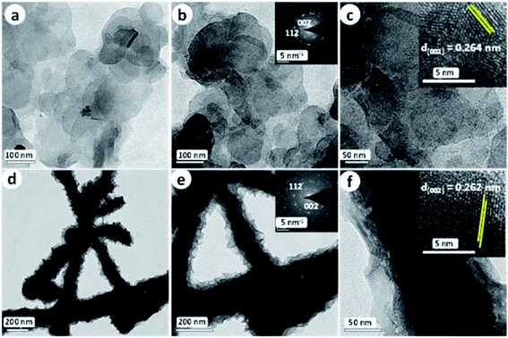 | ||
| Fig. 11 (a–c) TEM images of NiTe2 NFs. The insets of (b) and (c) are the respective SAED pattern and HRTEM image. (d–f) TEM images of NiTe2 NWs. The insets of (e) and (f) are the respective SAED pattern and HRTEM image. Reproduced with permission from ref. 91 (Copyright 2018 American Chemical Society). | ||
Interestingly, NiTe2 NWs actually outperformed the state-of-the-art HER electrocatalyst (Pt/C) in the higher overpotential region in both acidic and alkaline electrolytes while having comparable and slightly better Tafel slopes (Fig. 12a–d). Apart from this, Yang et al.92 have very recently reported the HER performance of NiTe nanorods that are vertically grown on a Ni foam electrode via a similar facile hydrothermal method. In this study, they also fabricated CoTe nanorods which upon electrochemical characterization were found to show a slightly better activity for the HER than NiTe nanorods. However, these catalysts did not deliver such high HER current densities within 500 mV as we observed earlier for our NiTe2 NW and NiTe2 NF catalysts.
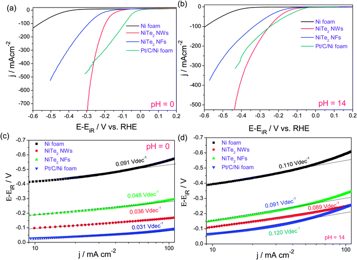 | ||
| Fig. 12 (a and b) HER LSVs of NiTe2 NWs, NiTe2 NFs, Ni foam and Pt/C–Ni foam in 0.5 M H2SO4 and 1.0 M KOH, respectively (sweep rate – 5 mV s−1). (c and d) Tafel plots of the same. Reproduced with permission from ref. 91 (Copyright 2018 American Chemical Society). | ||
This difference could be attributed to two factors, viz., (i) lower Te![[thin space (1/6-em)]](https://www.rsc.org/images/entities/char_2009.gif) :
:![[thin space (1/6-em)]](https://www.rsc.org/images/entities/char_2009.gif) Ni ratio in NiTe than in NiTe2 and (ii) higher difference in catalyst's mass loading. The above discussed are the only four reports on the utilization of nickel tellurides in the electrochemical hydrogen generation and the key activity markers are tabulated in Table 4. This implies that the use of nickel tellurides in the HER is a relatively new area of research and is at its young stage. Hence, we anticipate much more contributions from the research community in near future. As nickel tellurides have been poorly (relatively) explored, the opportunities and room to work with this material for HER electrocatalysis are abundant.
Ni ratio in NiTe than in NiTe2 and (ii) higher difference in catalyst's mass loading. The above discussed are the only four reports on the utilization of nickel tellurides in the electrochemical hydrogen generation and the key activity markers are tabulated in Table 4. This implies that the use of nickel tellurides in the HER is a relatively new area of research and is at its young stage. Hence, we anticipate much more contributions from the research community in near future. As nickel tellurides have been poorly (relatively) explored, the opportunities and room to work with this material for HER electrocatalysis are abundant.
| Catalyst | Medium | Loading/mg cm−2 | Overpotentiala/mV | Tafel slope/mV dec−1 | Reference |
|---|---|---|---|---|---|
| a Overpotentials were measured at a current density of 10 mA cm−2 unless otherwise mentioned. NA represents that the respective data were not available in the cited reports. | |||||
| NiTe | 0.5 M H2SO4 | NA | 422 | 87.4 | Bhat et al.90 |
| Layered NiTe2 | 0.5 M H2SO4 | NA | 560 | 41 | Chia et al.93 |
| NiTe2 nanowires/Ni foam | 0.5 M H2SO4 | 1.98 | 125 | 36 | Anantharaj et al.91 |
| NiTe2 nanoflakes/Ni foam | 0.5 M H2SO4 | 2.02 | 193 | 48 | Anantharaj et al.91 |
| NiTe nanorods/Ni foam | 1 M KOH | 1.3 | 202 | 185 | Yang et al.92 |
| NiTe2 nanowires/Ni foam | 1 M KOH | 1.98 | 113 | 69 | Anantharaj et al.91 |
| NiTe2 nanoflakes/Ni foam | 1 M KOH | 2.02 | 157 | 91 | Anantharaj et al.91 |
4.5. The most obvious question: which is the best? Sulphide or selenide or telluride?
This is the most obvious question that arises at the end of discussing all the key studies utilizing nickel chalcogenides in HER electrocatalysis. Even though the sulphides and selenides have been extensively studied for HER electrocatalysis, the attempts made to compare the HER activity between them and also with tellurides are unfortunately few. There have been only two studies which did such a comparison. Ren et al.86 recently prepared Ni3S2 and NiSe on nickel foam via a hydrothermal method and compared their HER activity in 1 M KOH. In this study, it is shown that Ni3S2 supported on Ni foam did perform better requiring 14 mV less than NiSe to deliver the benchmarking current density of 10 mA cm−2. However, this result cannot be taken as such to conclude that sulphides are better than selenides in catalysing the HER as this study has the following issues. The first one is the difference in the stoichiometry of Ni3S2 and NiSe which obviously shows that these two materials have two different crystal phases depending on which the active sites at the surface could vary. The second issue is that this study did not calculate the precise loading difference between these two. Moreover, this study did not include nickel telluride for comparison. This implies that a more systematic study was required then. Later, Ge et al.94 reported an interesting and systematic pilot study of comparing the HER activity of NiX2 in which X is varied from S to Te in the oxygen group of elements. To have a reasonable comparison, they maintained identical stoichiometry, identical mass loading and identical electrochemical conditions for HER studies in both acid and alkali. In this study, they found that NiS2, NiSe2 and NiTe2 required 213, 156 and 276 mV as overpotentials to deliver 10 mA cm−2 in acid and the same catalysts required 207, 164 and 256 mV as overpotentials in KOH. These observations clearly indicate that selenides of nickel are the best HER electrocatalysts in the pyrite-type NiX2 polymorph. Moreover, the calculated Tafel slopes were in accordance with the activity trend observed with LSVs. Though this study has shed light on the activity trend on the nickel chalcogenide catalysed HER electrocatalysis, it is limited only to the pyrite-type nickel dichalcogenides. Hence, we can anticipate many such studies for other forms of nickel chalcogenides in future. Such an improved performance of nickel selenides is generally related to moderate strength of Se–H bonds formed during the HER. As indicated in Section 2 of this review, only Se–H bonds have intermediate bond strength while S–H bonds are relatively stronger thereby requiring more activation energy for the desorption of H2 from the catalytic site and Te–H bonds are relatively weaker thereby requiring more activation energy for the adsorption of protons or water through H atoms. This clearly shows that the effect of these chalcogenide anions is crucial in determining the HER activity trend. Taking this view, one can interplay among these chalcogenide anions making heterostructured catalysts to get an optimized catalyst composition.Besides, other attractive areas of this field of nickel chalcogenide catalysed hydrogen generation are the study of the effect of the chalcogenide anions to nickel ratio, effect of electronegativity of chalcogenide anions, and effect of chalcogenide anions on the number of real-time electrochemically accessible sites. Based on the above discussion, we conclude here that at present, it is difficult to answer this question of deciding which is the best nickel chalcogenide to catalyse the HER. However, in an attempt to answer this question, researchers may add much new knowledge to this field which would overall benefit the development of non-precious metal based water electrolysers in future.
Finally, based on our own survey, we have provided a rough comparison among Ni–S, Ni–Se, and Ni–Te catalysts taking overpotential @ 10 mA cm−2, Tafel slope, stability and selectivity as activity markers (Fig. 13). In this scheme, an arbitrary unit in the range of 1 to 5 has been adopted to show the relative performance and nowhere the values directly indicate the actual values of the corresponding activity markers. For Tafel slope and overpotential a value of 1 is the best while for stability and selectivity a value of 5 is the best. Fig. 13 reveals that in terms of activity (overpotential and Tafel slope), Ni–Se catalysts are better than both Ni–S and Ni–Te catalysts. The same is also true for selectivity. On the other side, the stability of Ni–S catalysts is relatively superior to both Ni–Se and Ni–Te catalysts.
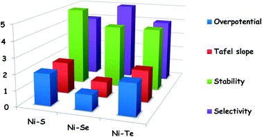 | ||
| Fig. 13 Mean HER performances of reported Ni–S, Ni–Se, and Ni–Te catalysts in terms of overpotential @ 10 mA cm−2, Tafel slope, stability, and selectivity. | ||
Having made such a comparison, it must be emphasized here that the trend shown above has been derived from catalysts with different stoichiometries, different loadings, different electroactive areas, and different substrate electrodes which have a significant effect on altering HER activity markers. Hence, there is a very high probability for deviation in the provided trend of these materials. Readers are strongly advised not to depend largely on this comparison.
5. Summary and outlook
Electrochemical generation of hydrogen from water has long been regarded as an efficient way of storing intermittent energies as hydrogen fuel and also as the fastest method of producing pure H2 with no apparent negative environmental impacts. The use of precious oxides and noble metals has so far been forbidding the successful commercialization of water electrolysers for cost-efficient production of hydrogen. However, there have always been significant efforts from the research community to replace these materials with non-precious ones such as 3d transition metal oxides/hydroxides, chalcogenides and pnictides. Among them, the chalcogenides of nickel are of interest to many groups of researchers due to their attractive HER electrocatalytic properties in both acid and alkali. Some of them have even been shown to possess appreciable HER activity in neutral water and sea water. To comprehensively summarize the recent progress in utilizing these nickel chalcogenides towards electrochemical hydrogen generation, we have dedicated this review to discuss all the noteworthy contributions made using sulphides, selenides and tellurides. Based on the preceding discussions of this review, it is concluded here that the nickel chalcogenides have promising HER activity with low overpotentials and Tafel slopes. However, their poor long-term stability, requirement for relatively higher catalyst loading and readiness towards surface anion exchange with hydroxides in alkali are the ones to be optimized to get the best out of them. In our discussions, we also indicated the available opportunities and challenges to be addressed with each type of nickel chalcogenide. Though there have been sufficient experimental studies showing the HER activity of nickel chalcogenides, the origin of HER activity with these materials remains elusive. Because, no one knew or showed (except a few DFT studies) how a poorly HER active metallic nickel which is easily poisoned at the surface due to the formation of strong M–H bonds could become a highly active HER electrocatalyst when it is chalcogenized. Theoretical modelling and calculations performed to reveal this puzzle had insisted one thing in common that the chalcogenide anions in nickel chalcogenides act as the proton adsorption hubs with relatively lower free energy of adsorption of protons when compared to Ni sites. This could be attributed to the negative charge on chalcogenide anions. However, such proton adsorbing abilities of chalcogenide anion sites cannot be attributed to the equally good HER activity observed in an alkaline medium. Hence, efforts must be taken to reveal other roles of chalcogenide anions in alkaline HER electrocatalysis.In future, many such theoretical and additional experimental studies must be carried out to investigate the origin of activity which would lead us to further optimize and formulate the best nickel chalcogenide HER electrocatalyst. Though nickel chalcogenides have shown promising HER activity, it is not comparable to that of Pt/C. To overcome this issue, it is expected that the strategy of noble metal (Pt or Ru) dilution by incorporating a small amount of either Pt or Ru into nickel chalcogenides should be deployed. In addition, to understand the real-time catalytic site evolution during the HER, new, highly advanced and sophisticated analytical techniques are also anticipated to evolve in near future. Overall, any new addition of knowledge to the field of electrochemical hydrogen generation from water either with nickel chalcogenides or with other materials will undoubtedly benefit the global community progressing towards the eco-friendly hydrogen-economy.
Conflicts of interest
The authors declare no conflicts of interest.Acknowledgements
S. A. wishes to acknowledge the Japan Society for the Promotion of Science (JSPS) for the award of a Standard Postdoctoral Fellowship (Fellowship ID: P18346). This work is supported in part by Grant-in-Aid for JSPS Fellows (JP19F18346) from the JSPS, Japan.References
- H. B. Gray, Nat. Chem., 2009, 1, 7 CrossRef CAS PubMed.
- A. Kirubakaran, S. Jain and R. K. Nema, Renewable Sustainable Energy Rev., 2009, 13, 2430–2440 CrossRef CAS.
- Y. Wang, K. S. Chen, J. Mishler, S. C. Cho and X. C. Adroher, Appl. Energy, 2011, 88, 981–1007 CrossRef CAS.
- L. Barelli, G. Bidini, F. Gallorini and S. Servili, Energy, 2008, 33, 554–570 CrossRef CAS.
- A. P. Simpson and A. E. Lutz, Int. J. Hydrogen Energy, 2007, 32, 4811–4820 CrossRef CAS.
- D. K. Liguras, D. I. Kondarides and X. E. Verykios, Appl. Catal., B, 2003, 43, 345–354 CrossRef CAS.
- T. Hisatomi, J. Kubota and K. Domen, Chem. Soc. Rev., 2014, 43, 7520–7535 RSC.
- A. Kudo and Y. Miseki, Chem. Soc. Rev., 2009, 38, 253–278 RSC.
- M.-R. Gao, Y.-F. Xu, J. Jiang and S.-H. Yu, Chem. Soc. Rev., 2013, 42, 2986–3017 RSC.
- Y. Kojima, K. Suzuki, K. Fukumoto, M. Sasaki, T. Yamamoto, Y. Kawai and H. Hayashi, Int. J. Hydrogen Energy, 2002, 27, 1029–1034 CrossRef CAS.
- Y. Shi and B. Zhang, Chem. Soc. Rev., 2016, 45, 1529–1541 RSC.
- S. Anantharaj, S. R. Ede, K. Sakthikumar, K. Karthick, S. Mishra and S. Kundu, ACS Catal., 2016, 6, 8069–8097 CrossRef CAS.
- J. Wang, W. Cui, Q. Liu, Z. Xing, A. M. Asiri and X. Sun, Adv. Mater., 2016, 28, 215–230 CrossRef CAS PubMed.
- S. Anantharaj, K. Karthick and S. Kundu, Materials Today Energy, 2017, 6, 1–26 CrossRef.
- E. Fabbri, A. Habereder, K. Waltar, R. Kötz, T. J. Schmidt, R. Kotz, T. J. Schmidt, R. Kötz, T. J. Schmidt, R. Kotz and T. J. Schmidt, Catal. Sci. Technol., 2014, 4, 3800–3821 RSC.
- M. Gong and H. Dai, Nano Res., 2014, 8, 23–39 CrossRef.
- H. Wendt and G. Imarisio, J. Appl. Electrochem., 1988, 18, 1–14 CrossRef CAS.
- M. Wang, Z. Wang, X. Gong and Z. Guo, Renewable Sustainable Energy Rev., 2014, 29, 573–588 CrossRef CAS.
- M. Gong, D. Y. Wang, C. C. Chen, B. J. Hwang and H. Dai, Nano Res., 2016, 9, 28–46 CrossRef CAS.
- M. Carmo, D. L. Fritz, J. Mergel and D. Stolten, Int. J. Hydrogen Energy, 2013, 38, 4901–4934 CrossRef CAS.
- A. T. Marshall, S. Sunde, M. Tsypkin and R. Tunold, Int. J. Hydrogen Energy, 2007, 32, 2320–2324 CrossRef CAS.
- S. Natarajan, S. Anantharaj, R. J. Tayade, H. C. Bajaj and S. Kundu, Dalton Trans., 2017, 46, 14382–14392 RSC.
- S. Anantharaj, P. E. Karthik, B. Subramanian and S. Kundu, ACS Catal., 2016, 6, 4660–4672 CrossRef CAS.
- S. Anantharaj, K. Karthick, M. Venkatesh, T. V. S. V. Simha, A. S. Salunke, L. Ma, H. Liang and S. Kundu, Nano Energy, 2017, 39, 30–43 CrossRef CAS.
- V. A. Alves, L. A. Da Silva, J. F. C. Boodts and S. Trassati, Electrochim. Acta, 1994, 39, 1585 CrossRef CAS.
- A. Di Blasi, C. D'Urso, V. Baglio, V. Antonucci, A. S. Arico', R. Ornelas, F. Matteucci, G. Orozco, D. Beltran, Y. Meas and L. G. Arriaga, J. Appl. Electrochem., 2009, 39, 191–196 CrossRef CAS.
- M. Yagi, E. Tomita, S. Sakita, T. Kuwabara and K. Nagai, J. Phys. Chem. B, 2005, 109, 21489 CrossRef CAS PubMed.
- T. Audichon, T. W. Napporn, C. Canaff, C. Morais, C. Comminges and K. B. Kokoh, J. Phys. Chem. C, 2016, 120, 2562–2573 CrossRef CAS.
- L. Ouattara, S. Fierro, O. Frey, M. Koudelka and C. Comninellis, J. Appl. Electrochem., 2009, 39, 1361–1367 CrossRef CAS.
- S. Anantharaj, P. E. Karthik and S. Kundu, J. Mater. Chem. A, 2015, 3, 24463–24478 RSC.
- S. Anantharaj and S. Kundu, Curr. Nanosci., 2017, 13, 333–341 CAS.
- R. Subbaraman, D. Tripkovic, D. Strmcnik, K.-C. Chang, M. Uchimura, A. P. Paulikas, V. Stamenkovic and N. M. Markovic, Science, 2011, 334, 1256–1260 CrossRef CAS.
- Y. Yan, B. Xia, Z. Xu and X. Wang, ACS Catal., 2014, 4, 1693–1705 CrossRef CAS.
- S. Jin, ACS Energy Lett., 2017, 2, 1937–1938 CrossRef.
- B. Han, M. Risch, Y. L. Lee, C. Ling, H. Jia and Y. Shao-Horn, Phys. Chem. Chem. Phys., 2015, 17, 22576–22580 RSC.
- J. O. M. Bockris and T. Otagawa, J. Electrochem. Soc., 1984, 131, 290 CrossRef CAS.
- X. Long, Z. Wang, S. Xiao, Y. An and S. Yang, Mater. Today, 2015, 19, 213–226 CrossRef.
- A. E. Henkes, Y. Vasquez and R. E. Schaak, J. Am. Chem. Soc., 2007, 129, 1896–1897 CrossRef CAS.
- T. F. Connolly, in Groups IV, V, and VI Transition Metals and Compounds: Preparation and Properties, ed. T. F. Connolly, Springer US, Boston, MA, 1972, pp. 179–197 Search PubMed.
- A. Ghezelbash and B. A. Korgel, Langmuir, 2005, 21, 9451–9456 CrossRef CAS PubMed.
- S. Anantharaj, S. R. Ede, K. Karthick, S. Sam Sankar, K. Sangeetha, P. E. Karthik, S. Kundu, E. K. Pitchiah and S. Kundu, Energy Environ. Sci., 2018, 11, 744–771 RSC.
- S. Anantharaj and S. Kundu, ACS Energy Lett., 2019, 1260–1264 CrossRef CAS.
- D. Voiry, M. Chhowalla, Y. Gogotsi, Y. Li, R. M. Penner and R. E. Schaak, ACS Nano, 2018, 12, 9635–9638 CrossRef CAS PubMed.
- T. Shinagawa, A. T. Garcia-Esparza and K. Takanabe, Sci. Rep., 2015, 5, 13801–13821 CrossRef PubMed.
- B. V. Tilak and C. P. Chen, J. Appl. Electrochem., 1993, 23, 631–640 CrossRef CAS.
- H. Vandenborre, P. Vermeiren and R. Leysen, Electrochim. Acta, 1984, 29, 297–301 CrossRef CAS.
- Q. Han, K. Liu, J. Chen and X. Wei, Int. J. Hydrogen Energy, 2003, 28, 1207–1212 CrossRef CAS.
- Q. Han, K. Liu, J. Chen, X. Li and X. Wei, Int. J. Hydrogen Energy, 2004, 29, 243–248 CrossRef CAS.
- Y. Çimen, A. W. Peters, J. R. Avila, W. L. Hoffeditz, S. Goswami, O. K. Farha and J. T. Hupp, Langmuir, 2016, 32, 12005–12012 CrossRef.
- T. W. Lin, C. J. Liu and C. S. Dai, Appl. Catal., B, 2014, 154–155, 213–220 CrossRef CAS.
- W. Zhu, X. Yue, W. Zhang, S. Yu, Y. Zhang, J. Wang and J. Wang, Chem. Commun., 2016, 52, 1486–1489 RSC.
- C. Ouyang, X. Wang, C. Wang, X. Zhang, J. Wu, Z. Ma, S. Dou, S. Wang, A. Canbin, O. Xin, W. Chen, W. Xiaoxu, C. Ouyang, X. Wang, C. Wang, X. Zhang, J. Wu, Z. Ma, S. Dou and S. Wang, Electrochim. Acta, 2015, 174, 297–301 CrossRef CAS.
- C. Tang, Z. Pu, Q. Liu, A. M. Asiri and X. Sun, Electrochim. Acta, 2015, 153, 508–514 CrossRef CAS.
- Z. Qin, Y. Chen, Z. Huang, J. Su, Z. Diao and L. Guo, J. Phys. Chem. C, 2016, 120, 14581–14589 CrossRef CAS.
- N. Jiang, Q. Tang, M. Sheng, B. You, D. E. Jiang and Y. Sun, Catal. Sci. Technol., 2016, 6, 1077–1084 RSC.
- Y. Deng, L. R. L. Ting, P. H. L. Neo, Y. J. Zhang, A. A. Peterson and B. S. Yeo, ACS Catal., 2016, 6, 7790–7798 CrossRef CAS.
- J. D. Benck, T. R. Hellstern, J. Kibsgaard, P. Chakthranont and T. F. Jaramillo, ACS Catal., 2014, 4, 3957–3971 CrossRef CAS.
- L. R. L. Ting, Y. Deng, L. Ma, Y. J. Zhang, A. A. Peterson and B. S. Yeo, ACS Catal., 2016, 6, 861–867 CrossRef CAS.
- X. Y. Yu, Y. Feng, Y. Jeon, B. Guan, X. W. D. Lou and U. Paik, Adv. Mater., 2016, 28, 9006–9011 CrossRef CAS PubMed.
- C. Wang, B. Tian, M. Wu and J. Wang, ACS Appl. Mater. Interfaces, 2017, 9, 7084–7090 CrossRef CAS PubMed.
- A. Sivanantham, P. Ganesan and S. Shanmugam, Adv. Funct. Mater., 2016, 26, 4661–4672 CrossRef CAS.
- Z. Ma, Q. Zhao, J. Li, B. Tang, Z. Zhang and X. Wang, Electrochim. Acta, 2018, 260, 82–91 CrossRef CAS.
- J. Liu, J. Wang, B. Zhang, Y. Ruan, L. Lv, X. Ji, K. Xu, L. Miao and J. Jiang, ACS Appl. Mater. Interfaces, 2017, 9, 15364–15372 CrossRef CAS PubMed.
- X. Long, G. Li, Z. Wang, H. Zhu, T. Zhang, S. Xiao, W. Guo and S. Yang, J. Am. Chem. Soc., 2015, 137, 11900–11903 CrossRef CAS PubMed.
- J. X. Feng, J. Q. Wu, Y. X. Tong and G. R. Li, J. Am. Chem. Soc., 2018, 140, 610–617 CrossRef CAS PubMed.
- Y. Qu, M. Yang, J. Chai, Z. Tang, M. Shao, C. T. Kwok, M. Yang, Z. Wang, D. Chua, S. Wang, Z. Lu and H. Pan, ACS Appl. Mater. Interfaces, 2017, 9, 5959–5967 CrossRef CAS PubMed.
- P. Wang, X. Zhang, J. Zhang, S. Wan, S. Guo, G. Lu, J. Yao and X. Huang, Nat. Commun., 2017, 8, 14580–14588 CrossRef CAS PubMed.
- M. R. Gao, Z. Y. Lin, T. T. Zhuang, J. Jiang, Y. F. Xu, Y. R. Zheng and S. H. Yu, J. Mater. Chem., 2012, 22, 13662–13668 RSC.
- C. Tang, N. Cheng, Z. Pu, W. Xing and X. Sun, Angew. Chem., Int. Ed., 2015, 54, 9351–9355 CrossRef CAS.
- T. Wang, X. Li, Y. Jiang, Y. Zhou, L. Jia and C. Wang, Electrochim. Acta, 2017, 243, 291–298 CrossRef CAS.
- B. Yu, Y. Hu, F. Qi, X. Wang, B. Zheng, K. Liu, W. Zhang, Y. Li and Y. Chen, Electrochim. Acta, 2017, 242, 25–30 CrossRef CAS.
- H. Wu, X. Lu, G. Zheng and G. W. Ho, Adv. Energy Mater., 2018, 8, 1702704–1702712 CrossRef.
- K. S. Bhat and H. S. Nagaraja, Int. J. Hydrogen Energy, 2018, 43, 19851–19863 CrossRef CAS.
- Y. Chen, Z. Ren, H. Fu, X. Zhang, G. Tian and H. Fu, Small, 2018, 14, 1800763–1800772 CrossRef.
- Z. Pu, Y. Luo, A. M. Asiri and X. Sun, ACS Appl. Mater. Interfaces, 2016, 8, 4718–4723 CrossRef CAS PubMed.
- F. Wang, Y. Li, T. A. Shifa, K. Liu, F. Wang, Z. Wang, P. Xu, Q. Wang and J. He, Angew. Chem., Int. Ed., 2016, 55, 6919–6924 CrossRef CAS PubMed.
- A. T. Swesi, J. Masud, W. P. R. Liyanage, S. Umapathi, E. Bohannan, J. Medvedeva and M. Nath, Sci. Rep., 2017, 7, 2401–2411 CrossRef.
- H. Li, S. Chen, H. Lin, X. Xu, H. Yang, L. Song and X. Wang, Small, 2017, 13, 1701487–1701494 CrossRef PubMed.
- S. Anantharaj, J. Kennedy and S. Kundu, ACS Appl. Mater. Interfaces, 2017, 9, 8714–8728 CrossRef CAS PubMed.
- S. Anantharaj, E. Subhashini, K. C. Swaathini, T. S. Amarnath, S. Chatterjee, K. Karthick and S. Kundu, Appl. Surf. Sci., 2019, 487, 1152–1158 CrossRef CAS.
- X. Zhou, Y. Liu, H. Ju, B. Pan, J. Zhu, T. Ding, C. Wang and Q. Yang, Chem. Mater., 2016, 28, 1838–1846 CrossRef CAS.
- C. Wang, P. Zhang, J. Lei, W. Dong and J. Wang, Electrochim. Acta, 2017, 246, 712–719 CrossRef CAS.
- B. Liu, Y.-F. Zhao, H.-Q. Peng, Z.-Y. Zhang, C.-K. Sit, M.-F. Yuen, T.-R. Zhang, C.-S. Lee and W.-J. Zhang, Adv. Mater., 2017, 1606521–1606529 CrossRef PubMed.
- C. Xia, H. Liang, J. Zhu, U. Schwingenschlögl and H. N. Alshareef, Adv. Energy Mater., 2017, 7, 1602089–1602097 CrossRef.
- T. Wang, D. Gao, W. Xiao, P. Xi, D. Xue and J. Wang, Nano Res., 2018, 11, 6051–6061 CrossRef CAS.
- H. Ren, Z. H. Huang, Z. Yang, S. Tang, F. Kang and R. Lv, J. Energy Chem., 2017, 26, 1217–1222 CrossRef.
- T. Liu, A. M. Asiri and X. Sun, Nanoscale, 2016, 8, 3911–3915 RSC.
- Z. Gao, J. Qi, M. Chen, W. Zhang and R. Cao, Electrochim. Acta, 2017, 224, 412–418 CrossRef CAS.
- X. Chia, Z. Sofer, J. Luxa and M. Pumera, Chem.–Eur. J., 2017, 23, 11719–11726 CrossRef CAS PubMed.
- K. S. Bhat, H. C. Barshilia and H. S. Nagaraja, Int. J. Hydrogen Energy, 2017, 42, 24645–24655 CrossRef CAS.
- S. Anantharaj, K. Karthick and S. Kundu, Inorg. Chem., 2018, 57, 3082–3096 CrossRef CAS PubMed.
- L. Yang, H. Xu, H. Liu, D. Cheng and D. Cao, Small Methods, 2019, 3, 1900113–1900123 CrossRef.
- X. Chia, Z. Sofer, J. Luxa and M. Pumera, Chem.–Eur. J., 2017, 23, 11719–11726 CrossRef CAS PubMed.
- Y. Ge, S.-P. Gao, P. Dong, R. Baines, P. M. Ajayan, M. Ye and J. Shen, Nanoscale, 2017, 9, 5538–5544 RSC.
Footnote |
| † Dedicated to the parents (Mr Sengeni Ramakrishnan and Mrs Rani Sengeni) of Dr S. Anantharaj on the occasion of their 35th wedding anniversary. |
| This journal is © The Royal Society of Chemistry 2020 |

