Research progress on vanadium-based cathode materials for sodium ion batteries
Qinghong
Wang
ab,
Jiantie
Xu
 *cd,
Wenchao
Zhang
d,
Minglei
Mao
a,
Zengxi
Wei
a,
Lei
Wang
a,
Chunyu
Cui
a,
Yuxuan
Zhu
b and
Jianmin
Ma
 *ae
*ae
aSchool of Physics and Electronics, Hunan University, Changsha 410082, P. R. China. E-mail: nanoelechem@hnu.edu.cn
bSchool of Chemistry and Chemical Engineering, Jiangsu Key Laboratory of Green Synthetic Chemistry for Functional Materials, Jiangsu Normal University, Xuzhou 221116, P. R. China
cSchool of Environment and Energy, Guangdong Provincial Key Laboratory of Atmospheric Environment and Pollution Control, South China University of Technology, Guangzhou 510640, China. E-mail: jiantiexu@scut.edu.cn
dInstitute for Superconducting and Electronic Materials, University of Wollongong, Wollongong 2500, Australia
eKey Laboratory of Advanced Energy Materials Chemistry (Ministry of Education), Nankai University, Tianjin 300071, P. R. China
First published on 11th April 2018
Abstract
Sodium ion batteries (SIBs) have attracted increasing attention as one of the most promising candidates for cost-effective, high-energy rechargeable batteries. Owing to their high theoretical capacity and energy density, and rich electrochemical interaction with Na+ (V2+–V5+), a large number of vanadium(V)-based cathode materials, including vanadium oxides (e.g., V2O5 and VO2), vanadium bronzes (e.g., NaxVO2, NaV3O8, NaV6O15 and δ-NH4V4O10), V-based phosphates (e.g., Na3V2(PO4)3, VOPO4, NaVOPO4, Na7V3(P2O7)4 and Na2(VO)P2O7) and F-containing V-based polyanions (e.g., NaVPO4F, Na3V2(PO4)2F3 and Na3(VOx)2(PO4)2F3−2x), have been explored for SIBs. In this review, we mainly summarize the basic structures, modified/optimized structures, synthetic methods and morphology control of V-based cathode materials for SIBs. Additionally, major drawbacks, emerging challenges and some perspectives on the development of V-based cathode materials for SIBs are also discussed.
1. Introduction
In recent years, efficient energy storage systems (ESSs) have attracted significant attention with the increasing exploration of clean and renewable energy sources (e.g., solar, wind, tide, hydropower, biomass and geothermal energy).1 Lithium ion batteries (LIBs) have dominated the market of portable and smart electronic devices for nearly three decades. This is mainly due to their high energy and power densities, long cycle life and environmental friendliness.2 However, owing to the resource shortage, high cost and geographic distribution of Li in the Earth's crust, a candidate for LIBs is needed.3 Alternatively, sodium ion batteries (SIBs) have recaptured attention mainly due to the abundance of Na (2.83 wt% vs. 0.01 wt% for Li), as well as similar chemical properties of Na to Li (the alkali metal family) and electrochemical mechanisms of SIBs to LIBs.4 Therefore, SIBs have been considered as an alternative to LIBs for ESSs in the future.The initial research on room-temperature SIBs dates back to the 1980s,5 not far behind that of LIBs initially developed in the 1970s. However, the studies on SIBs were almost interrupted in the following three decades. This is mainly attributed to the lower energy density of SIBs than LIBs, and the safety issues caused by the use of Na in SIBs. The former results from the higher potential of Na (∼0.3 V, vs. Li+/Li) and higher mass of the Na counterpart (∼3 times heavier than Li). The latter is due to the low melting point (∼97.7 °C) of Na, Na dendrite formation and interface aging problems. On the other hand, the exploration of available electrodes for SIBs that could accommodate Na+ with the larger radius of 1.02 Å (vs. 0.76 Å for Li+) during the discharge–charge process, especially the anode materials, was also a big challenge.6 For example, only a few studies focused on lead7 and hard carbons8 were reported. The reported electrochemical performance of these electrode materials was also far from expectation. Recently, the smart design and nano-engineering of electrode materials for high-performance LIBs are being applied for SIBs.9 However, similar to LIBs, SIBs are often limited by the energy and power densities of cathode materials.10 The exploration and optimization of cathode materials with a suitable voltage window, high reversible capacity and stable structure are of significant importance toward the applications of SIBs.11
To date, a large number of cathode materials for SIBs, including layered transition-metal oxides, transition-metal fluorides, phosphates, fluorophosphates, pyrophosphates, sulphides, sulphates, Prussian blue and organic polymers, have been explored and well summarized in some reviews.12 Among these reported cathodes, vanadium(V)-based cathode materials have attracted more attention due to their high operating voltages, theoretical capacities and energy densities (Fig. 1), as well as their rich electrochemical reaction with Na+. V (atomic no. 23 in the periodic table) from VB group has a valence electron layer of 3d34s2. All the five valence electrons of V atom can take part in bonding, thereby giving rise to a multivalent V from V2+ to V5+. Apart from the rich electrochemical properties of V (V2+ to V5+), the low price and abundant source also make V-based materials promising cathode candidates for SIBs. To date, the reported V-based materials can be mainly divided into four categories: vanadium oxides (e.g., V2O5 and VO2), vanadium bronzes (e.g., NaxVO2, NaV3O8, NaV6O15 and δ-NH4V4O10), V-based phosphates (e.g., Na3V2(PO4)3, VOPO4, NaVOPO4, Na7V3(P2O7)4, Na2(VO)P2O7) and F-containing V-based polyanions (e.g., NaVPO4F, Na3V2(PO4)2F3 and Na3(VOx)2(PO4)2F3−2x). In this review, we will summarize the basic structures, modified/optimized structures, synthetic methods and morphology control of V-based cathode materials for SIBs. In addition, major drawbacks, emerging challenges and some perspectives on the development of V-based electrode materials for SIBs will also be discussed.
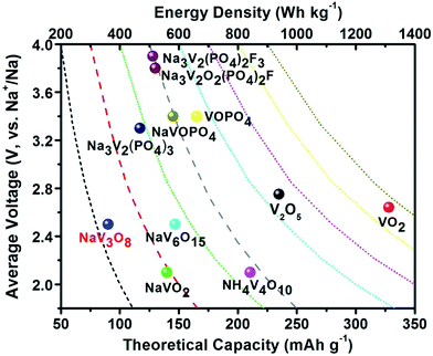 | ||
| Fig. 1 Average discharge potential (V, vs. Na+/Na) as a function of theoretical capacity (mA h g−1) and energy density (W h kg−1) of representative V-based materials as cathodes for SIBs. | ||
2. Vanadium oxides
For the construction of vanadium oxides, the multiple oxidation states of V, adjusting various coordination polyhedra and abundant two-dimensional structural frameworks are key factors.13 Generally, two-dimensional (2D) layered structures of vanadium oxides are formed by two units of [VO6] octahedra sharing corners, faces and/or edges. The [VO6] octahedra tend to be distorted into a square pyramid with a long V–O bond (2.1–2.79 Å, e.g., 2.79 Å for V2O5) and a short V![[double bond, length as m-dash]](https://www.rsc.org/images/entities/char_e001.gif) O bond (1.55–1.75 Å). As a result of this distortion, many layered structures appeared to form vanadium oxides. These layered structures together with large interlayer spacing are beneficial to accommodate Na+ and facilitate Na+ diffusion.14
O bond (1.55–1.75 Å). As a result of this distortion, many layered structures appeared to form vanadium oxides. These layered structures together with large interlayer spacing are beneficial to accommodate Na+ and facilitate Na+ diffusion.14
2.1. V2O5
V2O5 possesses a typical layered structure. The single-layered V2O5 is formed by two units of “double chain of edge-sharing VO6 octahedra” connected to each other.14a Within an α-V2O5 (orthorhombic, space group Pmmn) crystal structure, one of the terminal bonds (weak V–O bond) is shorter than other V–O bonds, which causes the vanadium coordination polyhedron to form a square pyramid (Fig. 2a). Due to the corner sharing of the double chains, adjacent [VO5] pyramids alternate in an up-up-down-down arrangement with every third row being vacant, as shown in Fig. 2b. On the other hand, because each single-layer of V2O5 is interconnected by the weak V–O bond, the interlayer spacing can be adjusted by intercalate species (e.g., organic or inorganic molecules) to form double layer δ-MxV4O10 (Fig. 2c).14a,15 When the intercalate species are removed, the δ-MxV4O10 structure collapses to form metastable vanadium dioxide VO2(B) (Fig. 2d).14a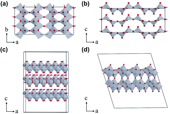 | ||
| Fig. 2 Crystal structures of vanadium oxides: (a) single layer and (b) layered-structure of orthorhombic V2O5, (c) δ-MxV4O10, (d) VO2(B). | ||
The layered V2O5 as a host material for Na+ storage was initially proposed early in 1988,16 however, very few reports focused on the study of the sodium storage properties of V2O5 in the following decades.17 Recently, V2O5 has been recaptured as a cathode material for SIBs due to its high theoretical capacity, as well as tremendous progress achieved towards its application in LIBs. Additionally, Mai's group investigated the Na+ storage mechanism of α-V2O5 on the basis of ex situ X-ray diffraction (XRD) measurements and Fourier transform infrared (FTIR) spectroscopy.18 They found that the initial phase transformation from α-V2O5 to NaV2O5, corresponding to a discharge capacity of 170 mA h g−1, was not completely reversible after subsequently charging back to 4.0 V. The irreversible phase change was suggested to be responsible for the quick capacity fading of α-V2O5 in the following cycles. Ali et al. also employed ex situ XRD and near edge X-ray absorption fine structure (NEXAFS) spectroscopy to study the Na+ insertion/extraction behavior of V2O5.19 They revealed that the full-discharged products of V2O5 were both NaV2O5 and Na2V2O5, indicating an oxidation state mixture of V (V4+/V5+) within the discharge product (Fig. 3a and b). Based on the redox reaction of V (V4+/V5+), V2O5 almost reached its theoretical capacity of ∼235 mA h g−1 (Fig. 3c). During the Na+ insertion process, V2O5 retained the high integrity in its structure, as evidenced by the increase of its lattice parameter c (also the unite cell) by only 9.09% after the full-sodiation process. The clear Na+ storage mechanism of α-V2O5 inspires more researchers to explore related studies.
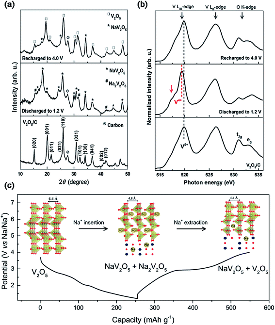 | ||
| Fig. 3 (a) XRD patterns and (b) NEXAFS of V2O5/C at the fully charged and discharged states. (c) Discharge–charge profiles and crystal structures (inset of (c)) at different voltage steps of V2O5/C. Reproduced with permission.19 Copyright 2016, American Chemical Society. | ||
Although the layer spacing of orthorhombic V2O5 (4.37 Å) is conducive for Li+ insertion/extraction, it is difficult for Na+ because of the larger radius of Na+ than Li+.17a,20 Moreover, the intrinsic low conductivity and diffusion coefficient of Na+ and large volume expansion also make V2O5 exhibit poor electrochemical performance.21 To address these issues, many strategies have been developed, including the morphological control of V2O5, modification of the crystal structure, surface and crystallinity of V2O5, and the hybridization of V2O5 with other conductive agents.
First of all, in order to mostly expose the active (110) plane of V2O5 to the electrolyte, Su et al.22 realized orthorhombic V2O5 hollow nanospheres with more exposure of (110) planes achieving good rate capability (e.g., 93.1 mA h g−1 at 320 mA g−1 after 100 cycles). Moreover, V2O5 with various other nanostructures also presented improved performance, like V2O5 nanobelts. V2O5 nanobelts with reduced particle size and carbon coating were prepared by an ambient dissolution–recrystallization process. Compared to the commercial V2O5 powder, orthorhombic V2O5 nanobelts exhibited a higher discharge capacity of 216 mA h g−1 at 0.5C.23 Furthermore, orthorhombic V2O5 encapsulated in nanoporous carbon, prepared by ambient hydrolysis deposition with a subsequent hydrolysis reaction, also delivered a high discharge capacity of 276 mA h g−1 at 40 mA g−1.24 The morphology control realizes the performance improvement of orthorhombic V2O5via the exposure of the active plane. Solution-phase synthetic methods are efficient to control the morphology of V2O5 nanostructures, however, the yield is usually low. Therefore, it is important to explore efficient methods for the morphological control of V2O5 for practical applications.
On the other hand, several studies have demonstrated that bilayered-V2O5 (with a larger interlayer spacing, and also belonging to an orthorhombic system) exhibited better Na+ storage performance than normal orthorhombic V2O5 due to the larger interlayer spacing of bilayered-V2O5.25 The large interlayer spacing of (001) provides bilayered-V2O5 with open channels for facile Na+ insertion and extraction. A bilayered-V2O5 electrode was prepared by using chemical deposition from VOSO4 solution on Ni foil, followed by a vacuum annealing process.26Fig. 4 shows the short/long range order of the bilayered-V2O5, which was well characterized by high resolution transmission electron microscopy (HRTEM), selected area electron diffraction (SAED), X-ray absorption near-edge spectra (XANES), and small and wide angle X-ray scattering (SAXS and WAXS). As shown in Fig. 4a, the bilayered-V2O5 showed void space between randomly spaced bilayers with much larger layer spacing (13.5 Å) than orthorhombic V2O5 (4.4 Å), as well as short-range order and shorter V![[double bond, length as m-dash]](https://www.rsc.org/images/entities/char_e001.gif) O bond. As a result, sodium insertion induces the formation of long- and short-range order in the bilayered-V2O5 structure, whereas sodium deintercalation causes the loss of long-range order and preserves the short-range order (Fig. 4b). When measured at 1.5–3.8 V (vs. Na+/Na), the bilayered-V2O5 delivered a high initial discharge capacity of 250 mA h g−1 at 20 mA g−1 and showed an initial capacity retention of 85% after 320 cycles. Another study also indicated that the interlayer spacing of bilayered-V2O5 nanobelts could be adjusted up to 11.53 Å (Fig. 4c). After the uptake of Na+, the interlayer spacing can be further expanded to 15.35 Å.27 Benefiting from the enlarged interlayer, the bilayered-V2O5 nanobelts displayed promising rate capability (e.g., reversible capacities of 231.4 mA h g−1 at 80 mA g−1 and 134 mA h g−1 at 640 mA g−1), as shown in Fig. 4d. The enlarged interlayer spacing endows bilayered-V2O5 with excellent rate capability. Therefore, it is necessary to explore the synthetic methods for preparing bilayered-V2O5 for cost-effective high-power SIBs. Apart from the crystalline V2O5 as electrode materials for SIBs, disordered or amorphous V2O5 also showed promising electrochemical performances.28 This is attributed to the isotropic characteristics of amorphous materials with a short-range order, which provide V2O5 with abundant-opening ion diffusion channels. In addition, amorphous materials can also be easily obtained at low temperature and in a short-time process.29 For example, the amorphous V2O5 electrode on Ni foam exhibited high reversible capacity of 241 mA h g−1 at the 2nd cycle and retained 160 mA h g−1 after 100 cycles.30 Despite the high capacity obtained, the cycling stability of amorphous V2O5 electrode should be further improved.
O bond. As a result, sodium insertion induces the formation of long- and short-range order in the bilayered-V2O5 structure, whereas sodium deintercalation causes the loss of long-range order and preserves the short-range order (Fig. 4b). When measured at 1.5–3.8 V (vs. Na+/Na), the bilayered-V2O5 delivered a high initial discharge capacity of 250 mA h g−1 at 20 mA g−1 and showed an initial capacity retention of 85% after 320 cycles. Another study also indicated that the interlayer spacing of bilayered-V2O5 nanobelts could be adjusted up to 11.53 Å (Fig. 4c). After the uptake of Na+, the interlayer spacing can be further expanded to 15.35 Å.27 Benefiting from the enlarged interlayer, the bilayered-V2O5 nanobelts displayed promising rate capability (e.g., reversible capacities of 231.4 mA h g−1 at 80 mA g−1 and 134 mA h g−1 at 640 mA g−1), as shown in Fig. 4d. The enlarged interlayer spacing endows bilayered-V2O5 with excellent rate capability. Therefore, it is necessary to explore the synthetic methods for preparing bilayered-V2O5 for cost-effective high-power SIBs. Apart from the crystalline V2O5 as electrode materials for SIBs, disordered or amorphous V2O5 also showed promising electrochemical performances.28 This is attributed to the isotropic characteristics of amorphous materials with a short-range order, which provide V2O5 with abundant-opening ion diffusion channels. In addition, amorphous materials can also be easily obtained at low temperature and in a short-time process.29 For example, the amorphous V2O5 electrode on Ni foam exhibited high reversible capacity of 241 mA h g−1 at the 2nd cycle and retained 160 mA h g−1 after 100 cycles.30 Despite the high capacity obtained, the cycling stability of amorphous V2O5 electrode should be further improved.
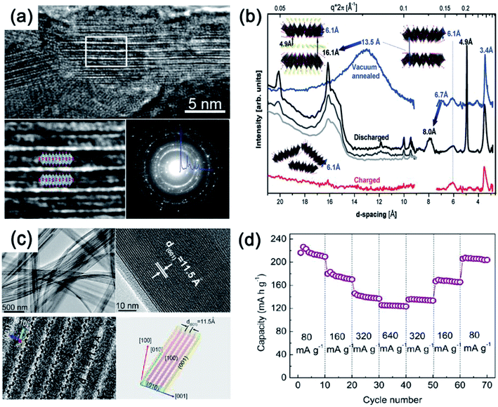 | ||
| Fig. 4 (a) HRTEM images and SAED pattern of V2O5. (b) SAXS (right) and WAXS (left) spectra of V2O5: electrochemically deposited vacuum annealed sample (blue) discharged at different currents of 630 μA (black), 120 μA (gray), 20 μA (light gray); and then charged at 120 μA (red). Inset of (b): model structures and interlayer spacing depicting transformations occurring upon Na+ intercalation and deintercalation. (c) TEM image (top-left), HRTEM (top-right and bottom-left) images and geometrical model (bottom-right) and (d) rate capability at various current densities from 80 to 640 mA g−1 of V2O5. (a, b) Reproduced with permission.26 Copyright 2013, American Chemical Society. (c, d) Reproduced with permission.27 Copyright 2012, American Chemical Society. | ||
The layered structure endows V2O5 with an ability to intercalate various organic or inorganic composites to form intercalated V2O5. The electrochemical performance of intercalated V2O5 is highly dependent on the types and quantities of inserted species.14b,31 The intercalated V2O5 xerogel with an interlayer spacing ranging from 8.8 to 13.8 Å, which usually originates from δ-HxV4O10, favors large amounts of Na+ storage within the V2O5 xerogel.32 A V2O5·nH2O (n = ∼0.55) xerogel with interconnected nanowire networks was prepared by a freeze-drying process.18 The amount of intercalated H2O (n) largely determines the interlayer spacing of V2O5·nH2O. Because large amounts of H2O may be detrimental to the electrode performance, an appropriate amount of water is highly required. As a result, benefiting from the large xerogel interlayer spacing of 12.3 Å (n = ∼0.55) and the nanowire networks, the V2O5·0.5H2O xerogel exhibited a higher initial discharge capacity of 338 mA h g−1 at 0.05 A g−1 and a high rate capacity of 96 mA h g−1 at 1.0 A g−1, which are comparable to those of orthorhombic V2O5. Both cyclic voltammetry (CV) measurements and theoretical calculation indicate that the open layer structure effectively ensures rapid Na+ diffusion and also provides V2O5 extra pseudocapacity. Nevertheless, the severe “lattice breathing” of V2O5 xerogel could cause the shrinkage and collapse of the layered V2O5 structure, leading to the deactivation of V2O5 and fast capacity decay.15,33 Besides, the conductivity of V2O5 xerogel (10−2–10−3 S cm−1) is also relatively low.34 Metal ions (e.g., Li+, Na+, Mg2+, Cu2+ and Zn2+) are also often intercalated within the V2O5 xerogel to improve the conductivity and stability of the V2O5 xerogel, leading to the high-performance of intercalated V2O5.14a,35 In particular, δ-NaxV2O5 nanowires were prepared by a chemical pre-intercalation synthesis approach with the use of orthorhombic α-V2O5 as the precursor, displaying a high discharge capacity of 365 mA h g−1 at 20 mA g−1.36 Therefore, it is important to explore optimized methods to realize the electrochemically stable V2O5 xerogel with high conductivity for high-energy/power cathode materials.
V2O5 is a promising cathode material with high capacity, as well as easy synthesis, however, several issues should still be addressed. First of all, how to delicately pre-sodiate V2O5 in practical full-cells is a great challenge when V2O5 and its composites do not contain sodium. Moreover, it is easy to synthesize V2O5 without using V5+ based salts as the precursors, however, it is not easy to achieve highly desirable performance through morphological and crystalline control as well as the intercalation of inserted species. Furthermore, the cycling stability of amorphous or intercalated V2O5 should also be considered in practical applications.
2.2. VO2
Although VO2 has a similar layered structure to V2O5, there are no vacancies in VO2, which is composed of layers of V2O4 pyramids with the up-down-up-down chess-board-like arrangement (Fig. 2d). There are four phases for VO2: VO2(R), VO2(M), VO2(A) and VO2(B). Among these phases, metastable VO2(B), which can be converted irreversibly to the thermodynamically stable VO2(M) or VO2(R) above 300 °C,37 has been widely investigated in the electrochemistry field. Within the VO2(B) crystal structure, the double layers of V4O10 share corners to form a shear-type structure containing a one-dimensional (1D) tunnel.38 Owing to the favorable characteristics of this 1D tunnel parallel to the [010] crystal orientation for insertion/extraction of Na+, VO2(B) has been investigated as the cathode for SIBs.39 During the Na+ intercalation process, the edge sharing along the direction of [010] increases the resistance to V–O bond cleavage, thereby effectively preventing the structural collapse.To reveal the Na+ insertion/extraction mechanism of single crystalline VO2 nanosheets, the theoretical calculation was performed based on the first-principles plane-wave pseudo-potential method implemented in the Cambridge Sequential Total Energy Package (CASTEP).40 As shown in Fig. 5a, the phase transformation of NaxVO2 during the Na+ insertion process becomes stable until x = 1, as evidenced by the lowest formation energy of NaxVO2 with x = 1. From x = 0.25 to x = 1.0, the volume change of NaxVO2 is only 7%, indicating the excellent structural stability of VO2 (Fig. 5b). The stable structure of VO2 nanosheets makes it possible for Na+ transportation (x < 1.0) even at high current rates, with a theoretical capacity of 323 mA h g−1 (i.e., VO2 + Na+ + e− = NaVO2). It should be noted that the Na+ storage mechanism in the following cycles may be expressed as NaVO2 ↔ NaxVO2 (0 < x < 0.5) + Na+ + e− (Fig. 5c), as indicated by the X-ray photoelectron spectroscopy (XPS) measurements on the discharged product of NaxVO2 (0 < x < 0.5) after charging to 4 V. Similar to the cases of V2O5/VOx,41–43 the hybridization of nanosized VO2 with carbon/graphene is an effective way to improve the electrochemical properties of VO2.44 For example, a “binder-free and flexible” electrode based on graphene quantum dots (GQDs) coated VO2(B) arrays/graphene displayed a high initial discharge capacity of 306 mA h g−1 at C/3 (i.e., ∼100 mA g−1) in the voltage range of 1.5–3.5 V (vs. Na+/Na). At a high rate of 5C, the electrode still delivered a high capacity of 247 mA h g−1 and retained a remarkable capacity retention of 91% after 500 cycles.45 Similar to V2O5, delicate pre-sodiation of VO2 for its application in full-cells is a great challenge. In addition, it also requires more strategies to effectively control the phases and valance of V in VO2.
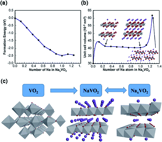 | ||
| Fig. 5 (a) The formation energy and (b) cell volume of NaxVO2 as a function of x in NaxVO2. The insets of (b): atomic structures of NaxVO2 with x = 0.25, 1 and 1.25. (c) Schematic presentation of the Na+ insertion/extraction mechanism of VO2. Reproduced and updated with permission.40 Copyright 2014, Elsevier. | ||
3. Vanadium bronzes
3.1. NaxVO2
Sodium layered oxides NaxMO2, (M = transition metal) are considered to be promising cathode candidates for SIBs mainly due to their simple layered structures, high theoretical capacities and easy synthesis routes.46 NaxMO2 is built up of edge-sharing MO6 octahedra. According to the stacking orientations of MO6 octahedral layers along the c-axis direction, NaxMO2 can be classified into O3-, P2-, and P3-type phases.47 The letters “O” and “P” represent the Na+ location site while the numbers “2” and “3” stand for distinguishable sodium layers. Electrochemical kinetics and performance are highly reliable on the phase of NaxMO2. This is because different contents of Na+ occupying various sites will result in different host structural stabilities. For example, Na+ within the O3-phase NaxMO2 (0.7 < x < 1) occupies octahedral sites and MO2 layers stack in an ABCABC pattern (Fig. 6a). Different from that for O3-phase NaxMO2, MO2 layer stacking in an ABBA pattern within P2-phase NaxMO2 occurs with x = ∼0.7 (Fig. 6b) and MO2 layer stacking of P3-phase NaxMO2 with an ABBCCA pattern occurs with x = ∼0.5 (Fig. 6c).12e Usually, O3-type NaxMO2 has the highest initial discharge capacity but poor cycling stability. This is due to the serious slab-gliding during the charge–discharge process. P3-phase NaxMO2 has the lowest capacity due to the smallest x. Compared to O3 type and P3-phase NaxMO2, P2-type NaxMO2 might be a better candidate.48It is difficult to obtain single NaxVO2 phase without impurities due to the possible phase conversion between oxygen and V3+ with high reducing activity.49 As a result, there were few studies on the structures of NaxVO2 and its related electrochemical properties.50 Recently, O3-phase and P2-phase NaxVO2 cathode materials have been investigated. Hamani et al.51 reported that both P2-Na0.7VO2 and O3-NaVO2 could reversibly accommodate 0.5 Na+ per unit formula at a voltage range of 1.6–1.7 V (vs. Na+/Na), giving rise to a reversible capacity of ∼120 mA h g−1. Delmas' group52 prepared pure NaVO2 by chemical reduction of NaVO3 in a H2 atmosphere and studied its phase transition behavior during the Na-deintercalation process. The Na-deintercalation process was reversible up to x = 0.5, corresponding to the capacity of 126.4 mA h g−1. Single-phase Na2/3VO2 and Na1/2VO2 can be electrochemically obtained at ∼1.8 V and 2.3 V, respectively. Furthermore, they also studied the structural change of P2–Na0.71VO2 by in situ XRD measurements.53 As shown in Fig. 7a, there are four single-phase-transformation steps observed during the sodium insertion/de-intercalation process (0.5 ≤ x ≤ 0.92). In situ XRD patterns (Fig. 7b) clearly show the presence of additional weak Bragg peaks in the 2θ-range of 23.4–23.8° (0.61 < x < 0.70), and 28.9–29.8° and 33.8–34.7° (0.53 < x < 0.57), indicating the existence of superstructures or modulated structures during the discharge–charge process. From the electrochemical point of view, however, the wide voltage variation and poor electrochemical performances of NaxVO2 still cannot satisfy the demand for practical application. Additionally, the control of phase purity is a requirement to realize the consistent performance of electrode materials, so the complexity in its phases also limits its applications.
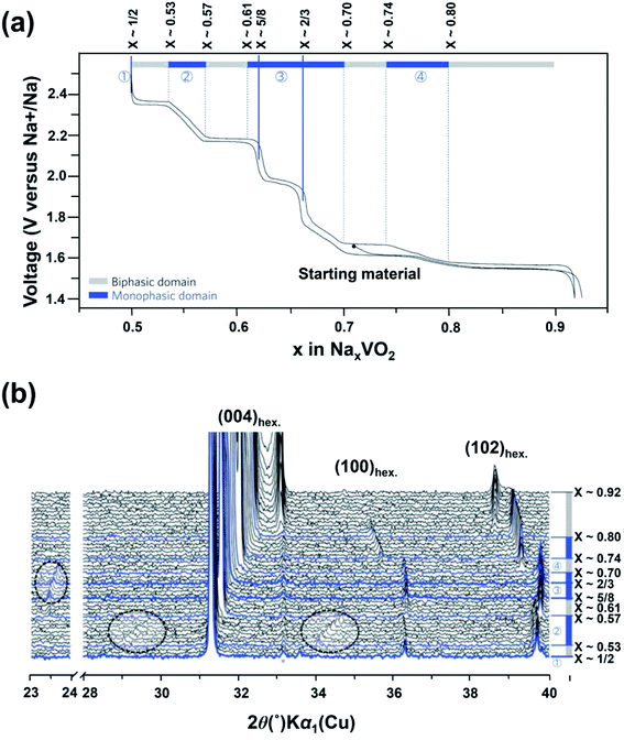 | ||
| Fig. 7 (a) Charge–discharge profile of NaxVO2 with the assigned region of biphasic domains and monophasic domains and (b) in situ XRD patterns of NaxVO2 recorded during the galvanostatic intermittent titration technique (GITT) experiments. (a, b) Reproduced and modified with permission.53 Copyright 2013, Nature Publishing Group. | ||
3.2. NaV3O8
Within the NaV3O8 crystal structure, Na+ occupies the octahedral sites between V3O8 polyhedral layers.54 Na+ can act as pillar cations to maintain the superior stability of the layered structure and thus allow NaV3O8 with Na+ insertion to form Na1+xV3O8. He et al.55 for the first time reported the Na+ storage in NaV3O8 based on a single-phase charge–discharge mechanism: NaV3O8 + xNa+ + xe− ↔ Na1+xV3O8. In order to further improve the electrochemical performance of NaV3O8, the composites and morphology of NaV3O8 were studied. A core–shell NaV3O8@ppy composite showed a discharge capacity of 99 mA h g−1 at 80 mA g−1 after 60 cycles.56 Na1.25V3O8 nanowires with a hierarchical zigzag structure were synthesized by a simple topotactic intercalation method.57 The hierarchical zigzag structure endows Na1.25V3O8 with a short Na+ diffusion pathway and prevents Na1.25V3O8 from structural collapse and self-aggregation during the Na+ insertion/extraction process. As a result, Na1.25V3O8 displayed a high initial capacity of 158.7 mA h g−1 at 200 mA g−1 in the voltage range of 1.5–4.0 V, with a capacity retention of 95% after 200 cycles. The good reversibility of Na1.25V3O8 was further revealed by in situ XRD measurements. At present, it remains challenging to precisely identify the occupancy site of Na+ in the insertion/extraction process and further determine the exact phase corresponding to each charge–discharge plateau.Similar to the case of V2O5·nH2O, Na2V6O16·nH2O with a typical layered structure is expected to provide large interstices between V3O8 layers to accommodate sodium ions. Deng et al. prepared a 1D nanostructured Na2V6O16·nH2O through a hydrothermal method.58 Na2V6O16·nH2O as an anode for aqueous LIBs displays a low reversible capacity of only ∼45 mA h g−1 and limited cycling performance in an aqueous full LIB using Na0.44MnO2 as the cathode. The poor electrochemical performance of Na2V6O16·nH2O is mainly due to its low electronic conductivity of 2.46 × 10⁻¹⁴ cm2 s−1 and the irreversible phase transition as evidenced by ex situ XRD. In order to achieve high performance Na2V6O16·nH2O for LIBs, how to stabilize the crystal structures of Na2V6O16·nH2O during the Na+ intercalation process in the initial cycles is important.
3.3. NaV6O15
To construct the NaV6O15 crystal structure, both VO5 pyramid and VO6 octahedra build up the ordered (V2O5)x frameworks with a tunnel along the b axis for Na+ location.59 Na+ can reversibly insert in/extract from the NaV6O15 nanorods along the b orientation. Several reports predicted that a maximum amount of 1.6 Na+ could be inserted into bulk NaV6O15, corresponding to a high theoretical capacity of 225 mA h g−1.60 So far, the obtained capacity of NaV6O15 is lower than the theoretical capacity, including NaV6O15 nanorods61 and NaV6O15 nanoflakes.62 For example, NaV6O15 nanorods showed a capacity of 142 mA h g−1 at 20 mA g−1 with a charge/discharge plateau at ∼2.5 V (vs. Na+/Na). Nevertheless, they still displayed reasonable rate capability due to the small size of the nanorods.3.4. δ-NH4V4O10
δ-NH4V4O10 is formed by V4O10 layers accommodating NH4+ between them (Fig. 8a).63 Each V4O10 layer is composed of two single-layer V2O5 sheets with short V![[double bond, length as m-dash]](https://www.rsc.org/images/entities/char_e001.gif) O bonds (1.6–1.7 Å). The adjacent V2O5–V2O5 sheets are linked by long trans bonds V⋯O.64 The interlayer spacing of δ-NH4V4O10 is 6.8 Å, indicating the ability for the accommodation of not only Li+ but also Na+ (Fig. 8b).63 Recently, δ-NH4V4O10 with various structures (e.g., nanorods, nanoflowers and nanobelts) have been prepared by hydrothermal methods and used as cathodes for SIBs.65 Fei et al.65b reported δ-NH4V4O10 nanorods with a high capacity of 186 mA h g−1 at 40 mA g−1 and good cycling stability in the voltage range of 1.5–3.5 V. Mitra's group66 prepared δ-NH4V4O10 nanobelts on a carbon coated Al-current collector (Fig. 8c). When it was used as a cathode for SIBs, the δ-NH4V4O10 electrode showed a high reversible capacity of 190 mA h g−1 at 200 mA g−1 (Fig. 8d) and 120 mA h g−1 at 1000 mA g−1 after 50 cycles. Sarkar et al.63 investigated the sodiation/desodiation mechanism of NaxNH4V4O10 by density functional theory (DFT) calculation. Theoretical cyclic voltammetry (CV) analysis indicated that NaxNH4V4O10 experienced multiple phase transformation in the voltage range of 1.5–3.5 V, especially with x > 1.0 at <1.88 V (Fig. 8e), which agrees well with previous experimental results. Moreover, it was found that the lattice volume of NaxNH4V4O10 decreased only by 3% at x = 1. When Na+ concentration increased from x > 1 to x = 3, the lattice volume of NaxNH4V4O10 increased by 17%, indicating the large distortion of NH4V4O10 frameworks after large uptake of Na+.
O bonds (1.6–1.7 Å). The adjacent V2O5–V2O5 sheets are linked by long trans bonds V⋯O.64 The interlayer spacing of δ-NH4V4O10 is 6.8 Å, indicating the ability for the accommodation of not only Li+ but also Na+ (Fig. 8b).63 Recently, δ-NH4V4O10 with various structures (e.g., nanorods, nanoflowers and nanobelts) have been prepared by hydrothermal methods and used as cathodes for SIBs.65 Fei et al.65b reported δ-NH4V4O10 nanorods with a high capacity of 186 mA h g−1 at 40 mA g−1 and good cycling stability in the voltage range of 1.5–3.5 V. Mitra's group66 prepared δ-NH4V4O10 nanobelts on a carbon coated Al-current collector (Fig. 8c). When it was used as a cathode for SIBs, the δ-NH4V4O10 electrode showed a high reversible capacity of 190 mA h g−1 at 200 mA g−1 (Fig. 8d) and 120 mA h g−1 at 1000 mA g−1 after 50 cycles. Sarkar et al.63 investigated the sodiation/desodiation mechanism of NaxNH4V4O10 by density functional theory (DFT) calculation. Theoretical cyclic voltammetry (CV) analysis indicated that NaxNH4V4O10 experienced multiple phase transformation in the voltage range of 1.5–3.5 V, especially with x > 1.0 at <1.88 V (Fig. 8e), which agrees well with previous experimental results. Moreover, it was found that the lattice volume of NaxNH4V4O10 decreased only by 3% at x = 1. When Na+ concentration increased from x > 1 to x = 3, the lattice volume of NaxNH4V4O10 increased by 17%, indicating the large distortion of NH4V4O10 frameworks after large uptake of Na+.
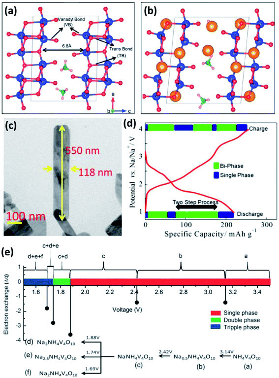 | ||
| Fig. 8 (a) Crystal structure of NH4V4O10 with short apical V–O and long trans V–O bonds, and (b) scheme of NH4V4O10 interaction with inserted ions (yellow solid spheres). (c) Field emission-scanning electron microscopy (FESEM) image and (d) initial charge–discharge profile of NH4V4O10 at 200 mA g−1. (e) Calculated potential of NaxNH4V4O10 with multiple phases in the voltage range of 1.5–3.5 V. (a, b and e) Reproduced with permission.63 Copyright 2016, Royal Society of Chemistry. (c, d) Reproduced with permission.66 Copyright 2015, American Chemical Society. | ||
4. V-based phosphates
V-based phosphates have been widely considered to be one of the most promising types of cathodes for SIBs because of their high operating potential, excellent thermal and structural stability, and high theoretical capacity.67 The distinguished features are derived from the inductive effect of the PO43− polyanion and strong P–O bond, ensuring the high working potential vs. Na+/Na and the stable structure during the charge–discharge process.68 To date, a large number of V-based phosphates have been investigated, including V-based single-phosphates (Na3V2(PO4)3, NaVOPO4, VOPO4), pyrophosphates (NaVP2O7, Na7V3(P2O7)4, t-Na2(VO)P2O7), fluorophosphates (NaVPO4F, Na3V2(PO4)2F3) and mixed-polyanions Na7V4(P2O7)4(PO4).4.1. V-based single-phosphates
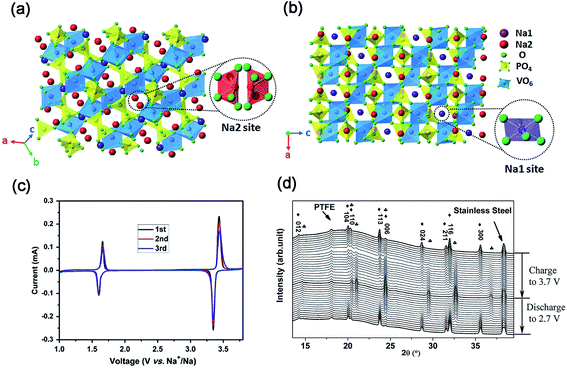 | ||
| Fig. 9 Schematic representation of the NASICON-Na3V2(PO4)3 structure in different direction-views: (a) Na1 site and (b) Na2 site. (c) CV curves of Na3V2(PO4)3/C in the voltage range of 1.0–3.8 V. (d) In situ XRD patterns of Na3V2(PO4)3/C in the voltage range of 2.7–3.7 V (♣ NaV2(PO4)3, ♦ Na3V2(PO4)3). (a, b) Reproduced with permission.71 Copyright 2015, Royal Society of Chemistry. (c) Reproduced with permission.75 Copyright 2011, Elsevier. (d) Reproduced with permission.77 Copyright 2015, Wiley-VCH. | ||
As shown in Fig. 9c, CV curves of the Na3V2(PO4)3 cell present two pairs of redox peaks at ∼3.40 and ∼1.63 V (vs. Na+/Na), corresponding to the redox reactions of V3+/V4+ and V2+/V3+, respectively.75 It demonstrates the potential use of Na3V2(PO4)3 as both cathode and anode for SIBs. To date, the electrochemical reaction mechanism of the Na3V2(PO4)3 cathode has been deeply investigated.76In situ XRD measurements revealed that a typical two-phase reaction between Na3V2(PO4)3 and NaV2(PO4)3 occurred in the voltage range of 2.7–3.7 V (vs. Na+/Na) during the charge/discharge process (Fig. 9d).77 Further analysis revealed that only Na occupying Na2 sites can be extracted from Na3V2(PO4)3 at room temperature. After two Na+ were extracted from Na2 sites, the skeleton structure of the host material is still preserved well with only a slight volume change.72d Based on the Na+ extraction from Na3V2(PO4)3 to NaV2(PO4)3, Na3V2(PO4)3 has a theoretical capacity of 117.6 mA h g−1.78 Furthermore, DFT calculation also indicated that Na+ might diffuse through two intra-layer pathways and one inter-layer pathway.79 The activated barriers for both intra-layer pathway and inter-layer pathway are 353 and 513 meV, respectively, which indicates that the diffusion of Na+ through the inside Na layers is more preferable.
Yamaki's group for the first time reported the electrochemical performance of Na3V2(PO4)3 with a high specific capacity of 140 mA h g−1 at a low current density of 0.1 mA cm−2 in the voltage range of 1.2–3.8 V (vs. Na+/Na).80 Since then, numerous effective strategies have been applied to modify Na3V2(PO4)3 to improve the intrinsic poor conductivity of Na3V2(PO4)3, including carbon decoration, downsizing the particles, designing tailored nanostructures and metal ion doping. First of all, carbon coating is one of the most preferred options for improving the electronic conductivity of electrode materials. Various carbon coated Na3V2(PO4)3 composites have been synthesized through solid state reactions,75,77 self-combustion method,81 pre-reduction-calcination process,82 glucose-assisted carbon-thermal reduction,83 C2H2-pyrolysis reduction,84 ball-milling–annealing process,85 ultrasonic spray pyrolysis process,86 sol–gel assisted method87 and so on. The as-reported Na3V2(PO4)3/C composites exhibited promising electrochemical performances as summarized in Table 1. The conductive carbon coating layer not only greatly enhances the electric conductivity of Na3V2(PO4)3/C but also effectively prevents Na3V2(PO4)3/C from severe aggregation. Jian et al.77 enhanced the electrochemical performance of Na3V2(PO4)3/C through the control of carbon coating with different contents, as well as the use of different electrolyte systems. Together with the use of sodium bis(fluorosulfonyl)imides/propylene carbonate (NaFSI/PC) as the electrolyte, a 3.8 wt% carbon coating makes Na3V2(PO4)3 deliver a high discharge capacity of 107.1 mA h g−1 at 0.1C with a high initial coulombic efficiency of 98.7%. In addition, doping carbon with non-metallic elements (e.g., N, B and S) has also been widely employed to enhance the conductivity of pristine carbon materials.71,88 It was found that doping carbon with BC2O and BCO2 could create numerous extrinsic defects and active sites, which allowed more surface Na+ absorption and fast diffusion of Na+ through the carbon coated layer, thus improving the rate performance of the Na3V2(PO4)3–C–B composites.71 Furthermore, reducing the particle size can further improve the utilization of active materials and shorten the diffusion path of Na+. Combined with an amorphous carbon shell with the thickness of few nanometers, a particle size of ∼40 nm allowed the nano-sized Na3V2(PO4)3 to deliver a high specific capacity of 94.9 mA h g−1 at 5C and superior capacity retention of 96.1% after 700 cycles.87b Recently, due to the abundant channels for Na+/electron transportation, Na3V2(PO4)3 with 3D hierarchitectures has attracted great attention.89 For example, combined with carbon coating, a 3D “foam-like” structure provides Na3V2(PO4)3 with a high specific capacity of 73 mA h g−1 at 100C and excellent cycle performance (∼100% capacity retention after 1000 cycles at 100C).89a In addition to the 3D “form-like” structure, a 3D honeycomb-type hierarchical microball also made Na3V2(PO4)3/C exhibit satisfactory electrochemical performance due to the synergistic effect of the hierarchical porous nanostructure and 3D continuous conductive framework.89b
| Electrode materials | Plateau voltage/potential range (V) | Specific capacity (mA h g−1) (1C = 117 mA g−1) | Rate capacity (mA h g−1) | Capacity retention | Reference |
|---|---|---|---|---|---|
| Na3V2(PO4)3 foam | ∼3.4, 2.5–3.8 | 112 at 1C | 51 at 200C | 99.5% after 100 cycles at 1C | 89a |
| Hierarchical Na3V2(PO4)3 particles | ∼3.4, 2.5–4.0 | 114.1 at 0.1C | 95.6 at 5C | 74% after 600 cycles at 1C | 89c |
| Na3V2(PO4)3 nanoparticles | ∼3.4, 2.5–4.0 | 83.71 at 0.1C | 48.87 at 10C | 74.3% after 100 cycles at 0.1C | 82b |
| Mesoporous Na3V2(PO4)3/C | ∼3.4, 2.8–3.8 | 98 at 0.1 A g−1 | 63 at 1 A g−1 | 74% after 450 cycles at 0.4 A g−1 | 82a |
| Na3V2(PO4)3/C | 2.5–3.8 | 100.72 at 0.1C | 61.76 at 30C | 95% after 50 cycles at 0.1C | 81 |
| Na3V2(PO4)3/C | ∼3.4, 2.7–3.7 | 107.1 at 0.1C | — | 93% after 80 cycles at 0.1C | 77 |
| Porous Na3V2(PO4)3/C | ∼3.4, 2.7–4.0 | 118.9 at 0.05C | 97.6 at 5C | 88.6% after 100 cycles at 5C | 87a |
| Na3V2(PO4)3/C porous hollow spheres | ∼3.4, 2.3–3.9 | 99.2 at 20 mA g−1 | 9.6 at 1 A g−1 | 90% after 300 cycles at 20 mA g−1 | 86 |
| Na3V2(PO4)3@C porous microspheres | ∼3.4, 2.2–3.8 | 112.8 at 0.2C | 70 at 10C | 90% after 400 cycles at 1C | 90a |
| Hierarchical porous Na3V2(PO4)3/C microballs | ∼3.4, 2.5–3.7 | 97.2 at 5C | 80.2 at 20C | 93.6% after 200 cycles at 1C | 89b |
| Na3V2(PO4)3/C nanofibers | ∼3.4, 2.7–4.0 | 112.5 at 0.1C | ∼88.9 at 50C | ∼93% after 300 cycles at 1C | 92a |
| CNTs modified Na3V2(PO4)3/C | ∼3.4, 2.5–3.8 | 107.6 at 0.5C | 81.7 at 10C | 93.9% after 500 cycles at 10C | 96b |
| Na3V2(PO4)3/C nanofibers | ∼3.4, 2.7–3.8 | 101 at 0.1C | 20 at 20C | ∼97% after 100 cycles at 2C | 92c |
| Na3V2(PO4)3@C@graphene | ∼3.4, 2.5–3.8 | 115 at 20C | 86 at 100C | 64% after 10![[thin space (1/6-em)]](https://www.rsc.org/images/entities/char_2009.gif) 000 cycles at 100C 000 cycles at 100C |
94a |
| Na3V2(PO4)3/C | ∼3.4, 2.5–3.8 | 117 at 0.33C | 65 at 2.67C | — | 76b |
| Na3V2(PO4)3/C | ∼3.4, 2.5–4.0 | 91.6 at 1C | 93.9 at 2C | 65% after 700 cycles at 2C | 84 |
| Na3V2(PO4)3/acetylene carbon | ∼3.4, 2.3–3.9 | 117.5 at 0.5 | 97 at 5C | 96.4% after 200 cycles at 5C | 91 |
| Na3V2(PO4)3@C | ∼3.4, 2.5–3.8 | 104.3 at 0.5C | 94.9 at 5C | 96.1% after 700 cycles at 5C | 87b |
| Layer-by-layer Na3V2(PO4)3@rGO | ∼3.4, 2.5–4.0 | 118 at 0.5C | 73 at 100C | 70% after 15![[thin space (1/6-em)]](https://www.rsc.org/images/entities/char_2009.gif) 000 cycles at 50C 000 cycles at 50C |
95 |
| 3D-skeleton-carbon coated Na3V2(PO4)3 | ∼3.4, 2.5–4.0 | 113 at 1C | 60 at 50C | 87.5% after 8000 cycles at 2C | 90b |
| Na3V2(PO4)3/nitrogen-decorated carbon | ∼3.4, 2.5–3.8 | 110.9 at 0.2C | 76.6 at 5C | — | 88a |
| Graphene-encapsulated Na3V2(PO4)3 | ∼3.4, 2.5–3.8 | 115.2 at 0.2C | 70.1 at 30C | 86.0% after 300 cycles at 5C | 93b |
| Graphene-supported Na3V2(PO4)3 | ∼3.4, 2.5–3.8 | 90.6 at 0.2C | 60.4 at 30C | 93% after 100 cycles at 1C | 93a |
| Na3V2(PO4)3/C nanofibers | ∼3.4, 2.5–4.0 | 106.8 at 0.2C | 103.0 at 2C | ∼100% after 125 cycles at 0.2C | 92b |
| Double-nanocarbon-modified Na3V2(PO4)3 | ∼3.4, 2.5–4.0 | 94.5 at 0.2C | 70 at 70C | 87% after 300 cycles at 30C | 96c |
| Na3V2(PO4)3/C/graphene | ∼3.4, 2.3–3.9 | 116.8 at 0.1C | 80 at 30C | 96.45% after 100 cycles at 0.2C | 88b |
| Na3V2(PO4)3@C/3D Gr | ∼3.4, 2.5–4.0 | 112 at 0.2C | 76 at 60C | 82% after 1500 cycles at 40C | 94b |
| Na3V2(PO4)3@C@CMK-3 | ∼3.4, 2.3–3.9 | 115 at 1C | 81 at 30C | 68% after 2000 cycles at 5C | 97 |
| Mg2+-Doped Na3V2(PO4)3/C | ∼3.4, 2.5–4.0 | 112.5 at 1C | 94.2 at 30C | 81% after 50 cycles at 20C | 99b |
| Na3V2−xFex(PO4)3/C (0 ≤ x ≤ 0.5) | ∼3.4, 2.0–4.3 | 115 at 0.5C | ∼110 at 2C | ∼100% after 40 cycles at 0.5C | 99a |
| Na3V1.8Al0.2(PO4)3/C | ∼3.4, 2.0–4.3 | 107 at 0.2C | 96.8 at 6C | 96% after 60 cycles at 0.5C | 99c |
| Na2.91K0.09V2(PO4)3/C | ∼3.4, 2.5–3.8 | 110.4 at 0.2C | 81.7 at 5C | >80% after 200 cycles at 1C | 98 |
| Mn-Doped Na3V2−xMnx(PO4)3/C | ∼3.4, ∼3.85, 2.0–4.3 | 104 at 0.5C | 104 at 2C | — | 99e |
| Li-Doped Na3−xLixV2(PO4)3/C | ∼3.4, 2.0–4.5 | 117.6 at 5C | 102 at 20C | — | 100 |
| B-Doping Na3V2(PO4)3/C | ∼3.4, 2.7–4.0 | 93.8 at 0.2C | 87.1 at 10C | 98% after 40 cycles at 0.2C | 101 |
| K3V2(PO4)3/C bundled nanowires | ∼1.6, ∼3.6, 1.5–4.0 | 119 at 0.1 A g−1 | ∼45 at 2 A g−1 | 99.0% after 2000 cycles at 1 A g−1 | 102 |
| Carbon coated Na3V2(PO4)3 | ∼3.4, 2.7–3.8 | 93 at 0.05C | 89 at 0.2C | 99% after 10 cycles at 5C | 75 |
Na3V2(PO4)3![[thin space (1/6-em)]](https://www.rsc.org/images/entities/char_2009.gif) : :![[thin space (1/6-em)]](https://www.rsc.org/images/entities/char_2009.gif) rGO–CNTs rGO–CNTs |
∼3.4, 2.3–4.0 | ∼117 at 1C | ∼82 at 100C | ∼96% after 2000 cycles at 10C | 89d |
| Na3V2(PO4)3/C composite | ∼3.4, 2.5–3.8 | 98.17 at 0.1C | 76.44 at 30C | 95.02% after 50 cycles at 0.1C | 83 |
| Porous sponge-like Na3V2(PO4)3/C | ∼3.4, 2.5–4.0 | 101.88 at 1C | 75.54 at 80C | 92.5% after 500 cycles at 70C | 103 |
| Na3V2(PO4)3 nanofibers/C | ∼3.4, 2.6–3.8 | 114 at 0.2C | 76 at 40C | 99.9% after 10![[thin space (1/6-em)]](https://www.rsc.org/images/entities/char_2009.gif) 000 cycles at 20C 000 cycles at 20C |
104 |
| Na3V2(PO4)3/rGO nanocomposites | ∼3.4, 2.7–3.9 | 113 at 100 mA g−1 | 98 at 2 A g−1 | 96.6% after 120 cycles at 100 mA g−1 | 105 |
| Hierarchical carbon framework wrapped Na3V2(PO4)3 | ∼3.4, 2–3.9 | 115 mA h g−1 at 0.2C | 38 at 500C | 54% after 20![[thin space (1/6-em)]](https://www.rsc.org/images/entities/char_2009.gif) 000 cycles at 30C 000 cycles at 30C |
106 |
| Na3V2(PO4)3/C nanocomposite | ∼3.4, 2.0–4.2 | 106 at 20 mA g−1 | 77 at 2 A g−1 | 90% after 50 cycles at 20 mA g−1 | 107 |
| N, S, F-doped carbon coated Na3V2(PO4)3 | ∼3.4, 2.5–3.8 | 117.5 at 1C | 93.4 at 10C | ∼95% after 1000 cycles at 10C | 108 |
| Na3V2(PO4)3/elastic carbon foam | ∼3.4, 2.5–4.0 | ∼117 at 0.5C | >60 at 20C | — | 109 |
| Porous Na3V2(PO4)3/C | ∼3.4, 2.3–3.9 | 114 at 1C | 106 at 10C | 50% after 30![[thin space (1/6-em)]](https://www.rsc.org/images/entities/char_2009.gif) 000 cycles at 40C 000 cycles at 40C |
110 |
Na3V2(PO4)3 supported on or embedded in highly conductive carbon matrixes (e.g., 0D–2D) also exhibited enhanced electrochemical kinetics.90 For example, Mai's group dispersed Na3V2(PO4)3 on 0D acetylene carbon (AC) nanospheres, 1D carbon nanotubes (CNTs) and 2D graphite nanosheets.91 These results indicated that the Na3V2(PO4)3 nanograins on the 0D AC displayed the best electrochemical performance with a high initial discharge capacity of 117.5 mA h g−1 at 0.5C and an excellent capacity retention of 96.4% at 5C after 200 cycles. Moreover, Na3V2(PO4)3 nanoparticles partly embedded in carbon nanofibers (CNFs), which were prepared by an electrospinning method,92a showed a high discharge capacity of ∼88.9 mA h g−1 at 50C and excellent capacity retention of ∼93% after 300 cycles at 1C. Furthermore, the use of 2D graphene to support or encapsulate Na3V2(PO4)3 (ref. 93) or wrap carbon coated Na3V2(PO4)3 (ref. 94) also displayed enhanced rate performances and cycling stability. As shown in Fig. 10a, the Na3V2(PO4)3@rGO composite with the “layer-by-layer” structure was prepared through modifying the surface charge of the gel precursor of Na3V2(PO4)3. Because of the confinement of Na3V2(PO4)3 nanocrystals in highly conductive rGO layers, the Na3V2(PO4)3@rGO composite showed high capacity (e.g., 118 mA h g−1 at 0.5C), excellent rate capability (73 mA h g−1 at 100C) and ultra-long cycle life (e.g., 70.0% capacity retention after 15![[thin space (1/6-em)]](https://www.rsc.org/images/entities/char_2009.gif) 000 cycles at 50C, Fig. 10b and c).95 Carbon coated nanosized Na3V2(PO4)3 embedded in a low-dimensional or 3D carbon matrix also delivered good electrochemical properties.96 Yu's group reported that carbon-coated Na3V2(PO4)3 nanoparticles impregnated into 3D mesoporous conductive and interconnected CMK-3 achieved a high reversible capacity of 81 mA h g−1 at 30C (Fig. 10d and e).97
000 cycles at 50C, Fig. 10b and c).95 Carbon coated nanosized Na3V2(PO4)3 embedded in a low-dimensional or 3D carbon matrix also delivered good electrochemical properties.96 Yu's group reported that carbon-coated Na3V2(PO4)3 nanoparticles impregnated into 3D mesoporous conductive and interconnected CMK-3 achieved a high reversible capacity of 81 mA h g−1 at 30C (Fig. 10d and e).97
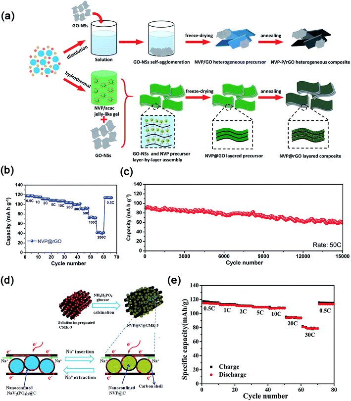 | ||
| Fig. 10 (a) Schematic illustration of the formation process, (b) rate performance and (c) ultra-long cycling stability of the layer-by-layer Na3V2(PO4)3@rGO composite. (d) Schematic illustration of the synthesis process and the reversibility of electrochemical reactions, (e) rate performance of Na3V2(PO4)3@C@CMK-3 composites. (a–c) Reproduced with permission.95 Copyright 2016, Wiley-VCH. (d, e) Reproduced with permission.97 Copyright 2015, Wiley-VCH. | ||
On the other hand, the introduction of metal ion dopants to Na3V2(PO4)3 makes Na3V2(PO4)3 display improved electrochemical performance. For example, the doping of K+ to the Na site of Na3V2(PO4)3 can greatly enhance the rate performance of Na3V2(PO4)3. This is due to the larger atomic size of K+ than that of Na+, which can significantly enlarge the lattice volume of Na3V2(PO4)3 along the c-axis and thus increase the Na+ diffusion pathway.98 As a result, K0.09–Na3V2(PO4)3/C presented a high reversible capacity of 110.4 mA h g−1 at 0.2C and ∼82 mA h g−1 at 5C. The metal (e.g., Fe, Mg, Al and Mn) doping or substitution to V can affect the electrochemical performance of Na3V2(PO4)3.99 For example, the Mg2+ doping in Na3V2−xMgx(PO4)3/C composites did not alter the host structure, which can effectively improve ionic/electronic conductivity, thus enhancing the rate capability.99b,d
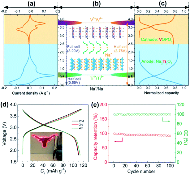 | ||
| Fig. 11 (a) CV curve of VOPO4 (orange) and Na2Ti3O7 (blue). (b) Schematic presentation of the potential of VOPO4, Na2Ti3O7 and the Na2Ti3O7//VOPO4 full cell. (c) Representative charge–discharge profiles of VOPO4 (orange) and Na2Ti3O7 (blue). (d) Charge–discharge profiles of the Na2Ti3O7//VOPO4-cell at 10 mA g−1. (e) The capacity retention and coulombic efficiency of the Na2Ti3O7//VOPO4 full cell at 100 mA g−1. Reproduced with permission.115 Copyright 2016, Royal Society of Chemistry. | ||
NaVOPO4 has several different crystal structures, such as triclinic α, tetragonal α-1 and orthorhombic β-NaVOPO4. The sodiation of VOPO4 (NaxVOPO4) with x = 1 yields NaVOPO4. The NaVOPO4 framework is composed of chains consisting of corner-sharing VO6 octahedra along the c axis in which the channels around each chain are filled by Na and P atoms.116 The framework offers NaVOPO4 3D tunnels for Na+ migration. The theoretical capacity of NaVOPO4 is 145 mA h g−1 (1 Na+ per formula unit).117 A series of β-NaxVOPO4 (x = 0, 0.1, 0.3, 0.5, 0.8 and 1.0) were prepared by a microwave-assisted solvothermal process.118 From the experimental result, β-NaxVOPO4 (x = 0 and 1.0) as a cathode material for SIBs displayed flat charge–discharge plateaus at the voltage range of 3.3–3.4 V (vs. Na+/Na) and involved the V4+/V5+ redox reactions.118 However, β-NaVOPO4 suffered from large irreversible capacity of each cycle for 50 cycles.
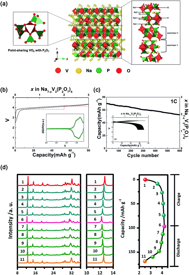 | ||
| Fig. 12 (a) Schematic illustration of the Na7V3(P2O7)4 structure together with Na+ diffusion path. (b) Charge–discharge profile of Na7V3(P2O7)4 with the calculated voltage (red dash line). Inset of (b): dQ/dV of the charge–discharge curve. (c) Cycling performance of Na7V3(P2O7)4 at 1C for 600 cycles. Inset of (c): charge–discharge profiles of Na7V3(P2O7)4 over 600 cycles. (d) Ex situ XRD patterns of Na7V3(P2O7)4 at different voltage steps of the corresponding initial charge–discharge curve. (a–c) Reproduced with permission.121 Copyright 2016, Wiley-VCH. (d) Reproduced with permission.122 Copyright 2016 Elsevier. | ||
4.2. V-based fluorophosphates
F-substitution to V-based phosphate cathodes for SIBs can significantly elevate the operating voltage of V-based phosphates due to the strong inductive effect of F anion.123 Recently, several F-containing V-based polyanions, such as NaVPO4F, Na3V2(PO4)2F3 and Na3(VOx)2(PO4)2F3−2x, have been reported as cathode materials for SIBs.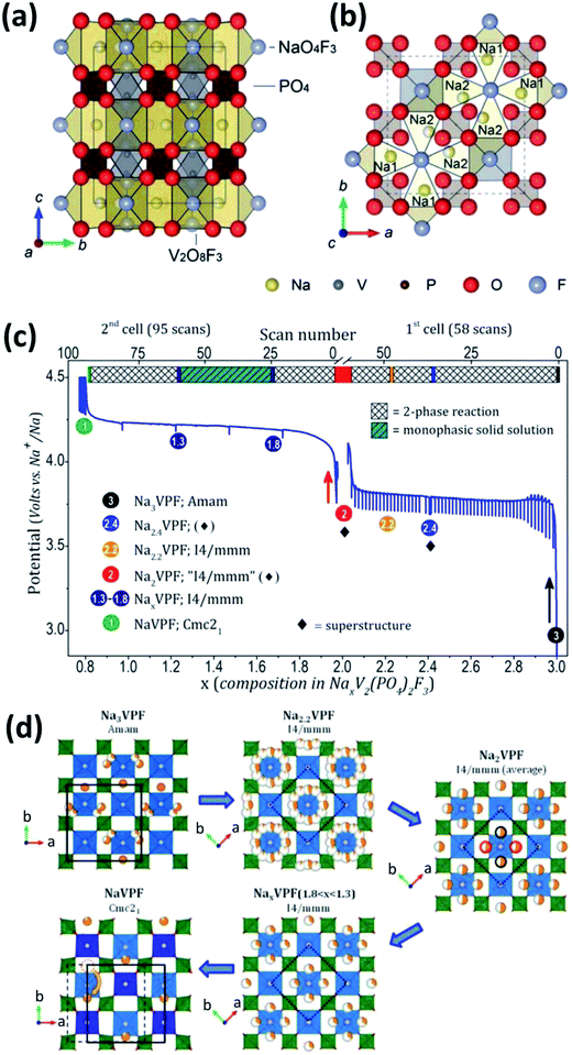 | ||
| Fig. 13 Schematic representation of the Na3V2(PO4)2F3 crystal structure viewed along the (a) a axis and (b) c axis. Na1 and Na2 in (b) are fully occupied Na sites and half occupied Na sites, respectively. (c) Electrochemical curves of potential-composition and (d) sodium distribution within NaxV2(PO4)2F3 (1 ≤ x ≤ 3). The red/black circles (extreme right of (d)) indicate that only two positions out of four are expected to be occupied. The orange dotted circle (bottom-left of (d)) shows that the sodium site in NaV2(PO4)2F3 is empty. (a, b) Reproduced with permission.130 Copyright 2012, Royal Society of Chemistry. (c, d) Reproduced with permission.132 Copyright 2015, American Chemical Society. | ||
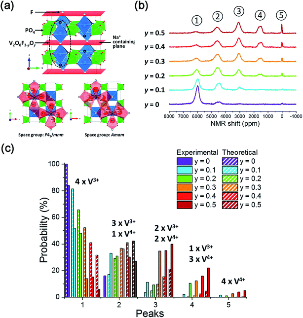 | ||
| Fig. 14 (a) Crystal structure of Na3V2(PO4)2F3–yO and possible Na Sites in Na3V2(PO4)2F3–yO. (b) 31P MAS NMR spectra of Na3V2(PO4)2F3–yOy (0 ≤ y ≤ 0.5). (c) Comparison of V4+/V3+ environments around P sites of Na3V2(PO4)2F3–yOy (0 ≤ y ≤ 0.5) obtained from the experimental and calculated results. Reproduced with permission.136 Copyright 2016, American Chemical Society. | ||
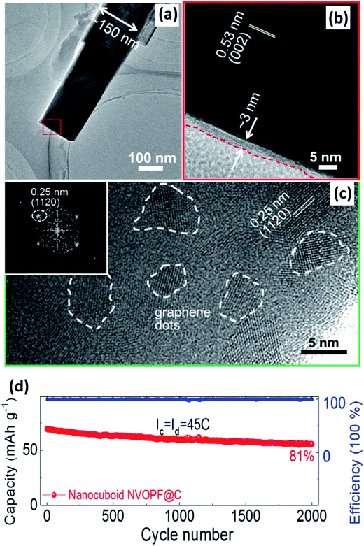 | ||
| Fig. 15 (a) TEM and (b) HRTEM of Na3(VO)2(PO4)2F@C. (c) HRTEM of GQD-anchored Na3(VO)2(PO4)2F@C with selected fast Fourier transform patterns of GQDs (inset of (c)). (d) Relatively long-term cycling performance of the GQD-anchored Na3(VO)2(PO4)2F@C electrode. Reproduced with permission.142a Copyright 2016 Elsevier. | ||
4.3. Mixed-polyanion Na7V4(P2O7)4(PO4)
The 3D framework of Na7V4(P2O7)4(PO4) can be described by the repeating (VP2O7)4PO4 unit in fourfold symmetry. In a (VP2O7)4PO4 unit, a central tetrahedron [PO4] shares corners with four [VO6] octahedra, and each diphosphate group [P2O7] bridges the two adjacent [VO6] octahedra by sharing the corners. Na+ occupies three different crystallographic positions (Na1, Na2 and Na3), adopting bipyramidal square planar and tetrahedral coordinations, respectively. Lim et al.146 reported that Na7V4(P2O7)4(PO4) displayed an initial capacity of 91.0 mA h g−1 and maintained it with an initial capacity retention of >78% over 1000 cycles. Na7V4(P2O7)4(PO4) exhibited a single potential plateau at ∼3.88 V (vs. Na+/Na), which can be attributed to the V3+/V4+ redox couple. However, Deng et al.147 found that the sodium de/intercalation within Na7V4(P2O7)4(PO4) nanorods not only involved the redox reaction of V4+/V3+ but also generated Na5V43.5+(P2O7)4(PO4) as the intermediate phase. This can be confirmed by the two pairs of potential plateaus at 3.87 V (V3+/V3.5+) and 3.89 V (V3.5+/V4+). However, the randomly distributed Na7V4(P2O7)4(PO4) nanorods suffer from limited electronic conductivity. In order to decrease the inconsecutive pathways for electron transport, they further reported a hierarchical Na7V4(P2O7)4(PO4)/C hybrid in which the Na7V4(P2O7)4(PO4)/C nanorod was coated by in situ residual carbon and enclosed by highly conductive 2D graphene.148 Benefiting from its hierarchical structure, the hybrid displayed outstanding rate capability (e.g., reversible capacities of 80.2 and 70.3 mA h g−1 at 10C and 20C, respectively). In addition, they further found that a “free-standing” 3D Na7V4(P2O7)4(PO4)–carbon foam used as a cathode for SIBs displayed a high initial capacity retention of 94% after 800 cycles at alternative rates of 20 and 3C.149 The complexity of the component limits the synthetic methods that could be used, and affects the phase purity, which in turn determines the electrochemical performance as a cathode material for SIBs.5. Conclusion and perspectives
In summary, as one of the most promising alternatives to LIBs, SIBs have attracted increasing attention for next-generation high-energy batteries. This is mainly due to the rich natural resources of Na and similar electrochemistry of SIBs to LIBs. Similar to their LIB counterparts, V-based electrode materials for SIBs have been widely demonstrated to deliver promising electrochemical performance. This is mainly attributed to their high operating voltage, theoretical capacity and energy density, along with the rich electrochemical interaction between Na and V with multiple oxidation states (V2+–V5+). Over the past several years, a large number of V-based electrode materials have been developed. They can be simply categorized into: vanadium oxides (e.g., V2O5, VOx and VO2), vanadium bronzes (e.g., NaxVO2, NaV3O8, NaV6O15 and δ-NH4V4O10), vanadium-based phosphates (e.g., Na3V2(PO4)3, VOPO4, NaVOPO4, Na7V3(P2O7)4, Na2(VO)P2O7) and F-containing V-based polyanions (e.g., NaVPO4F, Na3V2(PO4)2F3 and Na3(VOx)2(PO4)2F3−2x). In this review, we have mainly summarized research on the structural and electrochemical features of these vanadium based materials, as well as recent progress in their applications in SIBs. Despite the encouraging progress achieved in the development of V-based electrodes for SIBs, several scientific and practical issues remain, as follows:(1) The electrochemical behavior and performance of V-based materials are not only dependent on their inherent Na+ intercalation–deintercalation chemistry but also the occupancy and distribution of the constituent elements (e.g., Na, V, transition metals, O, F). Theoretical calculation is an effective tool to predict novel or optimized structures of V-based materials as high-performance cathodes for SIBs. As expected, it is highly desirable to explore novel V-based materials using theoretical calculation together with experiments.
(2) Morphology control (e.g., reduced particle-size, nanotubes, nanobelts, core–shell) and hybridization with other highly conductive materials (e.g., carbon-based materials) using various synthesis routes also significantly influence the electrochemical performance of V-based electrodes for SIBs. Therefore, novel, simple, eco-friendly and low cost synthesis methods for the preparation of V-based materials should be well developed.
(3) In order to achieve high capacity and energy density, V-based materials containing PO4− and F− anions are often employed at much higher voltages (vs. the potentials of conventional electrolytes). Thus, appropriate working electrolytes for those cell systems with the merits of larger electrochemical window and high anodic voltage, in addition to other merits (e.g., low melting point, low vaporization point, high ionic conductivity, safety and environmental friendliness), should be widely explored.
(4) The configuration of a SIB full-cell, which is based on V-based materials as both anode and cathode for SIBs, or as a high voltage cathode coupled with other promising negative anodes for SIBs, offers great advances in practical applications in the future. Although there have been a few reports on the full-cell configuration with the use of vanadium based materials (e.g., Na2Ti3O7//VOPO4 and Na3V2(PO4)3//Na3V2(PO4)3), the rate capability and cycling stability are still very limited, especially compared to their LIB counterparts. Therefore, rapid development of the high-performance SIB full-cell configuration with appropriate cathode materials (including V-based materials), as well as anodes and electrolytes, is highly necessary.
(5) Although there are a number of advantages for the development of V-based materials for SIBs, as well as LIBs, the disadvantages of the large-scale use of vanadium, in terms of vanadium being a “non-green” element (maybe harmful to the human body and the environment), and its relatively high cost should also be carefully considered in the future.
Conflicts of interest
There are no conflicts to declare.Acknowledgements
This work was supported by the National Natural Science Foundation of China (51302079, 51702138), the Natural Science Foundation of Hunan Province (2017JJ1008), the Natural Science Foundation of Jiangsu Province (BK20160213), the “Young Talent Fellowship” program from the South China University of Technology, the Australian Renewable Energy Agency (ARENA) S4 project and the 111 project (B12015).References
- (a) D. Larcher and J. M. Tarascon, Nat. Chem., 2015, 7, 19 CrossRef CAS PubMed; (b) J. Xu, Y. Chen and L. Dai, Nat. Commun., 2015, 6, 8103 CrossRef CAS PubMed; (c) C. P. Grey and J. M. Tarascon, Nat. Mater., 2016, 16, 45 CrossRef CAS PubMed; (d) L. Mei, J. Xu, Z. Wei, H. Liu, Y. Li, J. Ma and S. Dou, Small, 2017, 13, 1701441 CrossRef PubMed; (e) J. Xu, Y. Dou, Z. Wei, J. Ma, Y. Deng, Y. Li, H. Liu and S. Dou, Adv. Sci., 2017, 1700146 CrossRef PubMed; (f) C. Cui, J. Xu, L. Wang, D. Guo, M. Mao, J. Ma and T. Wang, ACS Appl. Mater. Interfaces, 2016, 8, 8568 CrossRef CAS PubMed; (g) D.-S. Bin, Z.-X. Chi, Y. T. Li, K. Zhang, X. Z. Yang, Y.-G. Sun, J.-Y. Piao, A.-M. Cao and L.-J. Wan, J. Am. Chem. Soc., 2017, 139, 13492 CrossRef CAS PubMed.
- (a) M. S. Whittingham, Chem. Rev., 2004, 104, 4271 CrossRef CAS PubMed; (b) H. Kim, J. Hong, K. Y. Park, H. Kim, S. W. Kim and K. Kang, Chem. Rev., 2014, 114, 11788 CrossRef CAS PubMed; (c) X. L. Deng, Z. X. Wei, C. Y. Cui, Q. H. Liu, C. Y. Wang and J. M. Ma, J. Mater. Chem. A, 2018, 6, 4013 RSC; (d) Z. Su, Z. X. Wei, C. Lai, H. Q. Deng, Z. X. Liu and J. Ma, Energy Storage Materials, 2018, 14, 129 CrossRef.
- (a) J. B. Goodenough and K. S. Park, J. Am. Chem. Soc., 2013, 135, 1167 CrossRef CAS PubMed; (b) M. L. Mao, C. Y. Cui, M. G. Wu, M. Zhang, T. Gao, X. L. Fan, J. Chen, T. H. Wang, J. M. Ma and C. S. Wang, Nano Energy, 2018, 45, 346 CrossRef CAS; (c) V. Etacheri, R. Marom, R. Elazari, G. Salitra and D. Aurbach, Energy Environ. Sci., 2011, 4, 3243 RSC; (d) J. Xu, J. Ma, Q. Fan, S. Guo and S. Dou, Adv. Mater., 2017, 29, 1606454 CrossRef PubMed; (e) X. Duan, J. Xu, J. Ma, S. Guo, H. Liu and S. Dou, Small Methods, 2017, 1, 1700156 CrossRef; (f) C. Y. Cui, Z. X. Wei, J. T. Xu, S. H. Liu, H. K. Liu, Y. Q. Zhang, M. L. Mao, S. Y. Wang, J. M. Ma and S. X. Dou, Energy Storage Materials, 2018, 15, 22 CrossRef.
- (a) V. Palomares, P. Serras, I. Villaluenga, K. B. Hueso, J. Carretero González and T. Rojo, Energy Environ. Sci., 2012, 5, 5884 RSC; (b) M. D. Slater, D. Kim, E. Lee and C. S. Johnson, Adv. Funct. Mater., 2013, 23, 947 CrossRef CAS; (c) N. Yabuuchi, K. Kubota, M. Dahbi and S. Komaba, Chem. Rev., 2014, 114, 11636 CrossRef CAS PubMed; (d) Q. Wang, W. Zhang, C. Guo, Y. Liu, C. Wang and Z. Guo, Adv. Funct. Mater., 2017, 27, 1703390 CrossRef; (e) J. J. Liang, X. Gao, J. Guo, C. M. Chen, K. Fan and J. M. Ma, Sci. China Mater., 2018, 61, 30 CrossRef; (f) C. Zhu, P. Yang, D. Chao, W. Mai and H. J. Fan, ChemNanoMat, 2015, 1, 458 CrossRef CAS; (g) J. J. Liang, C. C. Yuan, H. H. Li, K. Fan, Z. X. Wei, H. Q. Sun and J. M. Ma, Nano-Micro Lett., 2018, 10, 21 CrossRef.
- G. H. Newman and L. P. Klemann, J. Electrochem. Soc., 1980, 127, 2097 CrossRef CAS.
- J. Xu, M. Wang, N. P. Wickramaratne, M. Jaroniec, S. Dou and L. Dai, Adv. Mater., 2015, 27, 2042 CrossRef CAS PubMed.
- (a) Y. P. Ma, M. M. Doeff, S. J. Visco and L. C. Dejonghe, J. Electrochem. Soc., 1993, 140, 2726 CrossRef CAS; (b) T. R. Jow, L. W. Shacklette, M. Maxfield and D. Vernick, J. Electrochem. Soc., 1987, 134, 1730 CrossRef CAS.
- (a) D. A. Stevens and J. R. Dahn, J. Electrochem. Soc., 2000, 147, 4428 CrossRef CAS; (b) D. A. Stevens and J. R. Dahn, J. Electrochem. Soc., 2000, 147, 1271 CrossRef CAS; (c) P. Thomas and D. Billaud, Electrochim. Acta, 2001, 46, 3359 CrossRef CAS; (d) R. Alcántara, P. Lavela, G. F. Ortiz and J. L. Tirado, Electrochem. Solid-State Lett., 2005, 8, A222 CrossRef; (e) L. Wang, C. Yang, S. Dou, S. Wang, J. Zhang, X. Gao, J. Ma and Y. Yu, Electrochim. Acta, 2016, 219, 592 CrossRef CAS.
- J. Y. Hwang, S. T. Myung and Y. K. Sun, Chem. Soc. Rev., 2017, 46, 3529 RSC.
- (a) C. Nithya and S. Gopukumar, Energy Environ., 2015, 4, 253 CAS; (b) L. Wang, Y. Sun, L. Hu, J. Piao and J. Guo, J. Mater. Chem. A, 2017, 5, 8752 RSC; (c) J. Xu, S. Dou, H. Liu and L. Dai, Nano Energy, 2013, 2, 439 CrossRef CAS.
- P. K. Nayak, L. Yang, W. Brehm and P. Adelhelm, Angew. Chem., Int. Ed., 2018, 57, 102 CrossRef CAS PubMed.
- (a) P. Barpanda, S.-i. Nishimura and A. Yamada, Adv. Energy Mater., 2012, 2, 841 CrossRef CAS; (b) B. L. Ellis and L. F. Nazar, Curr. Opin. Solid State Mater. Sci., 2012, 16, 168 CrossRef CAS; (c) C. Masquelier and L. Croguennec, Chem. Rev., 2013, 113, 6552 CrossRef CAS PubMed; (d) H. Pan, Y. S. Hu and L. Chen, Energy Environ. Sci., 2013, 6, 2338 RSC; (e) M. H. Han, E. Gonzalo, G. Singh and T. Rojo, Energy Environ. Sci., 2015, 8, 81 RSC; (f) L. Wang, Y.-G. Sun, L.-L. Hu, J.-Y. Piao, J. Guo, A. Manthiram, J. M. Ma and A.-M. Cao, J. Mater. Chem. A, 2017, 5, 8752 RSC.
- P. Y. Zavalij and M. S. Whittingham, Acta Crystallogr., Sect. B: Struct. Sci., 1999, 55, 627 CrossRef.
- (a) N. A. Chernova, M. Roppolo, A. C. Dillon and M. S. Whittingham, J. Mater. Chem., 2009, 19, 2526 RSC; (b) L. Shao, J. W. Jeon and J. L. Lutkenhaus, Chem. Mater., 2012, 24, 181 CrossRef CAS.
- D. McNulty, D. N. Buckley and C. O'Dwyer, J. Power Sources, 2014, 267, 831 CrossRef CAS.
- K. West, Solid State Ionics, 1988, 28–30, 1128 CrossRef.
- (a) L. Y. Su, J. Winnick and P. Kohl, J. Power Sources, 2001, 101, 226 CrossRef CAS; (b) P. E. Tang, J. S. Sakamoto, E. Baudrin and B. Dunn, J. Non-Cryst. Solids, 2004, 350, 67 CrossRef CAS.
- Q. Wei, J. Liu, W. Feng, J. Sheng, X. Tian, L. He, Q. An and L. Mai, J. Mater. Chem. A, 2015, 3, 8070 CAS.
- G. Ali, J. H. Lee, S. H. Oh, B. W. Cho, K. W. Nam and K. Y. Chung, ACS Appl. Mater. Interfaces, 2016, 8, 6032 CAS.
- (a) D. W. Murphy, P. A. Christian, F. J. DiSalvo and J. V. Waszczak, Inorg. Chem., 1979, 18, 2800 CrossRef CAS; (b) A. M. Cao, J. S. Hu, H. P. Liang and L. J. Wan, Angew. Chem., Int. Ed., 2005, 44, 4391 CrossRef CAS PubMed; (c) C. K. Chan, H. Peng, R. D. Twesten, K. Jarausch, X. F. Zhang and Y. Cui, Nano Lett., 2007, 7, 490 CrossRef CAS PubMed; (d) C. Zhang, Z. Chen, Z. Guo and X. W. Lou, Energy Environ. Sci., 2013, 6, 974 RSC.
- D. Chao, X. Xia, J. Liu, Z. Fan, C. F. Ng, J. Lin, H. Zhang, Z. X. Shen and H. J. Fan, Adv. Mater., 2014, 26, 5794 CrossRef CAS PubMed.
- D. W. Su, S. X. Dou and G. X. Wang, J. Mater. Chem. A, 2014, 2, 11185 CAS.
- X. Rui, Y. Tang, O. I. Malyi, A. Gusak, Y. Zhang, Z. Niu, H. T. Tan, C. Persson, X. Chen, Z. Chen and Q. Yan, Nano Energy, 2016, 22, 583 CrossRef CAS.
- V. Raju, J. Rains, C. Gates, W. Luo, X. Wang, W. F. Stickle, G. D. Stucky and X. Ji, Nano Lett., 2014, 14, 4119 CrossRef CAS PubMed.
- H. Y. Li, C. H. Yang, C. M. Tseng, S. W. Lee, C. C. Yang, T. Y. Wu and J. K. Chang, J. Power Sources, 2015, 285, 418 CrossRef CAS.
- S. Tepavcevic, H. Xiong, V. R. Stamenkovic, X. Zuo, M. Balasubramanian, V. B. Prakapenka, C. S. Johnson and T. Rajh, ACS Nano, 2012, 6, 530 CrossRef CAS PubMed.
- D. Su and G. Wang, ACS Nano, 2013, 7, 11218 CrossRef CAS PubMed.
- (a) O. B. Chae, J. Kim, I. Park, H. Jeong, J. H. Ku, J. H. Ryu, K. Kang and S. M. Oh, Chem. Mater., 2014, 26, 5874 CrossRef CAS; (b) J. Liu, M. Zheng, X. Shi, H. Zeng and H. Xia, Adv. Funct. Mater., 2016, 26, 919 CrossRef CAS; (c) Y. Huang, Z. Lin, M. Zheng, T. Wang, J. Yang, F. Yuan, X. Lu, L. Liu and D. Sun, J. Power Sources, 2016, 307, 649 CrossRef CAS.
- S. Liu, Z. Tong, J. Zhao, X. Liu, J. Wang, X. Ma, C. Chi, Y. Yang, X. Liu and Y. Li, Phys. Chem. Chem. Phys., 2016, 18, 25645 RSC.
- E. Uchaker, Y. Z. Zheng, S. Li, S. L. Candelaria, S. Hu and G. Z. Cao, J. Mater. Chem. A, 2014, 2, 18208 CAS.
- (a) W. H. Smyrl, S. Passerini, M. Giorgetti, F. Coustier, M. M. Fay and B. B. Owens, J. Power Sources, 2001, 97–98, 469 CrossRef CAS; (b) M. Giorgetti, M. Berrettoni and W. H. Smyrl, Chem. Mater., 2007, 19, 5991 CrossRef CAS.
- (a) V. Petkov, P. N. Trikalitis, E. S. Bozin, S. J. L. Billinge, T. Vogt and M. G. Kanatzidis, J. Am. Chem. Soc., 2002, 124, 10157 CrossRef CAS PubMed; (b) A. Moretti, F. Maroni, I. Osada, F. Nobili and S. Passerini, ChemElectroChem, 2015, 2, 529 CrossRef CAS; (c) H. H. Kristoffersen and H. Metiu, J. Phys. Chem. C, 2016, 120, 3986 CrossRef CAS.
- H. He, G. Jin, H. Wang, X. Huang, Z. Chen, D. Sun and Y. Tang, J. Mater. Chem. A, 2014, 2, 3563 CAS.
- X. Zhang, H. Sun, Z. Li, J. Xu, S. Jiang, Q. Zhu, A. Jin and G. S. Zakharova, J. Electrochem. Soc., 2013, 160, H587 CrossRef CAS.
- Y. Wei, C. W. Ryu and K. B. Kim, J. Power Sources, 2007, 165, 386 CrossRef CAS.
- M. Clites, B. W. Byles and E. Pomerantseva, J. Mater. Chem. A, 2016, 4, 7754 CAS.
- (a) C. Tsang and A. Manthiram, J. Electrochem. Soc., 1997, 144, 520 CrossRef CAS; (b) D. Munozrojas and E. Baudrin, Solid State Ionics, 2007, 178, 1268 CrossRef CAS; (c) J. H. Son, J. Wei, D. Cobden, G. Cao and Y. Xia, Chem. Mater., 2010, 22, 3043 CrossRef CAS; (d) H. Liu, Y. Wang, K. Wang, E. Hosono and H. Zhou, J. Mater. Chem., 2009, 19, 2835 RSC.
- (a) F. Théobald, R. Cabala and J. Bernard, J. Solid State Chem., 1976, 17, 431 CrossRef; (b) Y. Oka, T. Yao, N. Yamamoto, Y. Ueda and A. Hayashi, J. Solid State Chem., 1993, 105, 271 CrossRef CAS.
- (a) C. Nethravathi, B. Viswanath, J. Michael and M. Rajamath, Carbon, 2012, 50, 4839 CrossRef CAS; (b) S. Yang, Y. Gong, Z. Liu, L. Zhan, D. P. Hashim, L. Ma, R. Vajtai and P. M. Ajayan, Nano Lett., 2013, 13, 1596 CrossRef CAS PubMed; (c) X. Xia, D. Chao, C. F. Ng, J. Lin, Z. Fan, H. Zhang, Z. X. Shen and H. J. Fan, Mater. Horiz., 2015, 2, 237 RSC.
- W. Wang, B. Jiang, L. Hu, Z. Lin, J. Hou and S. Jiao, J. Power Sources, 2014, 250, 181 CrossRef CAS.
- H. Kim, D. Y. Kim, Y. Kim, S. S. Lee and K. Park, ACS Appl. Mater. Interfaces, 2015, 7, 1477 CAS.
- H. Kim, R. H. Kim, S. S. Lee, Y. Kim, D. Y. Kim and K. Park, ACS Appl. Mater. Interfaces, 2014, 6, 11692 CAS.
- Q. Wei, Z. Jiang, S. Tan, Q. Li, L. Huang, M. Yan, L. Zhou, Q. An and L. Mai, ACS Appl. Mater. Interfaces, 2015, 7, 18211 CAS.
- (a) M. S. Balogun, Y. Luo, F. Lyu, F. Wang, H. Yang, H. Li, C. Liang, M. Huang, Y. Huang and Y. Tong, ACS Appl. Mater. Interfaces, 2016, 8, 9733 CrossRef CAS PubMed; (b) H. Fei, Z. Li, W. Feng and X. Liu, Dalton Trans., 2015, 44, 146 RSC.
- D. Chao, C. Zhu, X. Xia, J. Liu, X. Zhang, J. Wang, P. Liang, J. Lin, H. Zhang, Z. X. Shen and H. J. Fan, Nano Lett., 2015, 15, 565 CrossRef CAS PubMed.
- (a) J. J. Ding, Y. N. Zhou, Q. Sun and Z. W. Fu, Electrochem. Commun., 2012, 22, 85 CrossRef CAS; (b) J. Billaud, G. Singh, A. R. Armstrong, E. Gonzalo, V. Roddatis, M. Armand, T. Rojo and P. G. Bruce, Energy Environ. Sci., 2014, 7, 1387 RSC; (c) X. Li, X. Ma, D. Su, L. Liu, R. Chisnell, S. P. Ong, H. Chen, A. Toumar, J. C. Idrobo, Y. Lei, J. Bai, F. Wang, J. W. Lynn, Y. S. Lee and G. Ceder, Nat. Mater., 2014, 13, 586 CrossRef CAS PubMed.
- C. Delmas, C. Fouassier and P. Hagenmuller, Physica B+C, 1980, 99, 81 CrossRef CAS.
- (a) A. Mendiboure, C. Delmas and P. Hagenmuller, J. Solid State Chem., 1985, 57, 323 CrossRef CAS; (b) I. Saadoune, A. Maazaz, M. Menetrier and C. Delmas, J. Solid State Chem., 1996, 122, 111 CrossRef CAS; (c) D. H. Lee, J. Xu and Y. S. Meng, Phys. Chem. Chem. Phys., 2013, 15, 3304 RSC.
- (a) M. G. Barker and A. J. Hooper, Chem. Informationsdienst, 1972, 9, 1513 Search PubMed; (b) B. L. Chamberland and K. Porter, J. Solid State Chem., 1988, 73, 398 CrossRef CAS.
- (a) T. M. McQueen, P. W. Stephens, Q. Huang, T. Klimczuk, F. Ronning and R. J. Cava, Phys. Rev. Lett., 2008, 101, 166402 CrossRef CAS PubMed; (b) O. Szajwaj, E. Gaudin, F. Weill, J. Darriet and C. Delmas, Inorg. Chem., 2009, 48, 9147 CrossRef CAS PubMed; (c) Z. W. Ouyang, N. M. Xia, S. S. Sheng, J. Chen, Z. C. Xia, G. H. Rao and X. H. Zheng, Phys. Rev. B: Condens. Matter Mater. Phys., 2011, 83, 94417 CrossRef; (d) C. Didier, M. Guignard, J. Darriet and C. Delmas, Inorg. Chem., 2012, 51, 11007 CrossRef CAS PubMed.
- D. Hamani, M. Ati, J. M. Tarascon and P. Rozier, Electrochem. Commun., 2011, 13, 938 CrossRef CAS.
- C. Didier, M. Guignard, C. Denage, O. Szajwaj, S. Ito, I. Saadoune, J. Darriet and C. Delmas, Electrochem. Solid-State Lett., 2011, 14, A75 CrossRef CAS.
- M. Guignard, C. Didier, J. Darriet, P. Bordet, E. Elkaim and C. Delmas, Nat. Mater., 2013, 12, 74 CrossRef CAS PubMed.
- M. E. Spahr, P. Novak, W. Scheifele, O. Haas and R. Nesper, J. Electrochem. Soc., 1998, 145, 421 CrossRef CAS.
- H. He, G. Jin, H. Wang, X. Huang, Z. Chen, D. Sun and Y. Tang, J. Mater. Chem. A, 2014, 2, 3563 CAS.
- H. Kang, Y. Liu, M. Shang, T. Lu, Y. Wang and L. Jiao, Nanoscale, 2015, 7, 9261 RSC.
- Y. Dong, S. Li, K. Zhao, C. Han, W. Chen, B. Wang, L. Wang, B. Xu, Q. Wei, L. Zhang, X. Xu and L. Mai, Energy Environ. Sci., 2015, 8, 1267 CAS.
- C. Deng, S. Zhang, Z. Dong and Y. Shang, Nano Energy, 2014, 4, 49–55 CrossRef CAS.
- C. Presura, M. Popinciuc, P. H. van Loosdrecht, D. van der Marel, M. Mostovoy, T. Yamauchi and Y. Ueda, Phys. Rev. Lett., 2003, 90, 026402 CrossRef CAS PubMed.
- (a) S. Bach and N. Baffier, Solid State Ionics, 1989, 27, 41 CrossRef; (b) J. P. Pereira-Ramos and R. Messina, Solid State Ionics, 1990, 40–41, 970 CrossRef CAS.
- H. Liu, H. Zhou, L. Chen, Z. Tang and W. Yang, J. Power Sources, 2011, 196, 814 CrossRef CAS.
- H. He, X. Zeng, H. Wang, N. Chen, D. Sun, Y. Tang, X. Huang and Y. Pan, J. Electrochem. Soc., 2014, 162, A39 CrossRef.
- T. Sarkar, P. Kumar, M. D. Bharadwaj and U. Waghmare, Phys. Chem. Chem. Phys., 2016, 18, 9344 RSC.
- N. Wang, W. Chen, L. Mai and Y. Dai, J. Solid State Chem., 2008, 181, 652 CrossRef CAS.
- (a) S. Sarkar, P. S. Veluri and S. Mitra, Electrochim. Acta, 2014, 132, 448 CrossRef CAS; (b) H. Fei, X. Liu, Y. Lin and M. Wei, J. Colloid Interface Sci., 2014, 428, 73 CrossRef CAS PubMed.
- A. Sarkar, S. Sarkar, T. Sarkar, P. Kumar, M. D. Bharadwaj and S. Mitra, ACS Appl. Mater. Interfaces, 2015, 7, 17044 CAS.
- (a) H. Kim, H. Kim, Z. Ding, M. H. Lee, K. Lim, G. Yoon and K. Kang, Adv. Energy Mater., 2016, 6, 1600943 CrossRef; (b) Y. Fang, J. Zhang, L. Xiao, X. Ai, Y. Cao and H. Yang, Adv. Sci., 2017, 1600392 CrossRef PubMed.
- (a) A. Yamada, S. C. Chung and K. Hinokuma, J. Electrochem. Soc., 2001, 148, A224 CrossRef CAS; (b) H. Kim, I. Park, D. H. Seo, S. Lee, S. W. Kim, W. J. Kwon, Y. U. Park, C. S. Kim, S. Jeon and K. Kang, J. Am. Chem. Soc., 2012, 134, 10369 CrossRef CAS PubMed.
- (a) N. Anantharamulu, K. Koteswara Rao, G. Rambabu, B. Vijaya Kumar, V. Radha and M. Vithal, J. Mater. Sci., 2011, 46, 2821 CrossRef CAS; (b) W. Zhou, L. Xue, X. Lu, H. Gao, Y. Li, S. Xin, G. Fu, Z. Cui, Y. Zhu and J. B. Goodenough, Nano Lett., 2016, 16, 7836 CrossRef CAS PubMed; (c) X. Xiang, K. Zhang and J. Chen, Adv. Mater., 2015, 27, 5343 CrossRef CAS PubMed.
- (a) P. Senguttuvan, G. Rousse, M. E. Arroyo y de Dompablo, H. Vezin, J. M. Tarascon and M. R. Palacin, J. Am. Chem. Soc., 2013, 135, 3897 CrossRef CAS PubMed; (b) C. Fang, Y. Huang, W. Zhang, J. Han, Z. Deng, Y. Cao and H. Yang, Adv. Energy Mater., 2016, 6, 1501727 CrossRef.
- W. Shen, H. Li, C. Wang, Z. Li, Q. Xu, H. Liu and Y. Wang, J. Mater. Chem. A, 2015, 3, 15190 CAS.
- (a) H. Kabbour, D. Coillot, M. Colmont, C. Masquelier and O. Mentre, J. Am. Chem. Soc., 2011, 133, 11900 CrossRef CAS PubMed; (b) M. Pivko, I. Arcon, M. Bele, R. Dominko and M. Gaberscek, J. Power Sources, 2012, 216, 145 CrossRef CAS; (c) A. K. Padhi, K. S. Nanjundaswamy, C. Masquelier and J. B. Goodenough, J. Electrochem. Soc., 1997, 144, 2581 CrossRef CAS; (d) Z. Jian, C. Yuan, W. Han, X. Lu, L. Gu, X. Xi, Y. S. Hu, H. Li, W. Chen, D. Chen, Y. Ikuhara and L. Chen, Adv. Funct. Mater., 2014, 24, 4265 CrossRef CAS.
- S. Y. Lim, H. Kim, R. A. Shakoor, Y. Jung and J. W. Choi, J. Electrochem. Soc., 2012, 159, A1393 CrossRef CAS.
- J.-N. Chotard, G. Rousse, R. David, O. Mentré, M. Courty and C. Masquelier, Chem. Mater., 2015, 27, 5982 CrossRef CAS.
- Z. Jian, L. Zhao, H. Pan, Y.-S. Hu, H. Li, W. Chen and L. Chen, Electrochem. Commun., 2012, 14, 86 CrossRef CAS.
- (a) L. S. Plashnitsa, E. Kobayashi, Y. Noguchi, S. Okada and J.-i. Yamaki, J. Electrochem. Soc., 2010, 157, A536 CrossRef CAS; (b) J. Kang, S. Baek, V. Mathew, J. Gim, J. Song, H. Park, E. Chae, A. K. Rai and J. Kim, J. Mater. Chem., 2012, 22, 20857 RSC.
- Z. Jian, W. Han, X. Lu, H. Yang, Y.-S. Hu, J. Zhou, Z. Zhou, J. Li, W. Chen, D. Chen and L. Chen, Adv. Energy Mater., 2013, 3, 156 CrossRef CAS.
- W. Song, X. Cao, Z. Wu, J. Chen, K. Huangfu, X. Wang, Y. Huang and X. Ji, Phys. Chem. Chem. Phys., 2014, 16, 17681 RSC.
- K. M. Bui, V. A. Dinh, S. Okada and T. Ohno, Phys. Chem. Chem. Phys., 2015, 17, 30433 RSC.
- Y. Uebou, T. Kiyabu, S. Okada and J.-i. Yamaki, The Reports of Institute of Advanced Material Study, Kyushu University, 2002, vol. 16, p. 1 Search PubMed.
- H. Wang, D. Jiang, Y. Zhang, G. Li, X. Lan, H. Zhong, Z. Zhang and Y. Jiang, Electrochim. Acta, 2015, 155, 23 CrossRef CAS.
- (a) T. F. Hung, W. J. Cheng, W. S. Chang, C. C. Yang, C. C. Shen and Y. L. Kuo, Chem, 2016, 22, 10620 CrossRef CAS PubMed; (b) N. Van Nghia, S. Jafian and I. M. Hung, J. Electron. Mater., 2016, 45, 2582 CrossRef.
- G. Li, D. Jiang, H. Wang, X. Lan, H. Zhong and Y. Jiang, J. Power Sources, 2014, 265, 325 CrossRef CAS.
- L. Si, Z. Yuan, L. Hu, Y. Zhu and Y. Qian, J. Power Sources, 2014, 272, 880 CrossRef CAS.
- R. Klee, M. J. Aragón, R. Alcántara, J. L. Tirado and P. Lavela, Eur. J. Inorg. Chem., 2016, 47, 3212 CrossRef.
- J. Mao, C. Luo, T. Gao, X. Fan and C. Wang, J. Mater. Chem. A, 2015, 3, 10378 CAS.
- (a) W. Shen, C. Wang, H. Liu and W. Yang, Chem, 2013, 19, 14712 CrossRef CAS PubMed; (b) W. Duan, Z. Zhu, H. Li, Z. Hu, K. Zhang, F. Cheng and J. Chen, J. Mater. Chem. A, 2014, 2, 8668 RSC.
- (a) P. Nie, Y. Zhu, L. Shen, G. Pang, G. Xu, S. Dong, H. Dou and X. Zhang, J. Mater. Chem. A, 2014, 2, 18606 RSC; (b) J. Z. Guo, X. L. Wu, F. Wan, J. Wang, X. H. Zhang and R. S. Wang, Chem, 2015, 21, 17371 CrossRef CAS PubMed.
- (a) Y. Zhou, X. Rui, W. Sun, Z. Xu, Y. Zhou, W. J. Ng, Q. Yan and E. Fong, ACS Nano, 2015, 9, 4628 CrossRef CAS PubMed; (b) Q. Wang, B. Zhao, S. Zhang, X. Gao and C. Deng, J. Mater. Chem. A, 2015, 3, 7732 RSC; (c) H. Li, X. Bi, Y. Bai, Y. Yuan, R. Shahbazian-Yassar, C. Wu, F. Wu, J. Lu and K. Amine, Adv. Mater. Interfaces, 2016, 3, 1500740 CrossRef; (d) C. Zhu, P. Kopold, P. A. van Aken, J. Maier and Y. Yu, Adv. Mater., 2016, 28, 2409 CrossRef CAS PubMed.
- (a) S. Tao, P. Cui, W. Huang, Z. Yu, X. Wang, S. Wei, D. Liu, L. Song and W. Chu, Carbon, 2016, 96, 1028 CrossRef CAS; (b) Q. Zhang, W. Wang, Y. Wang, P. Feng, K. Wang, S. Cheng and K. Jiang, Nano Energy, 2016, 20, 11 CrossRef CAS.
- S. Li, Y. Dong, L. Xu, X. Xu, L. He and L. Mai, Adv. Mater., 2014, 26, 3545 CrossRef CAS PubMed.
- (a) J. Yang, D. W. Han, M. R. Jo, K. Song, Y. I. Kim, S. L. Chou, H. K. Liu and Y. M. Kang, J. Mater. Chem. A, 2015, 3, 1005 RSC; (b) H. Li, Y. Bai, F. Wu, Y. Li and C. Wu, J. Power Sources, 2015, 273, 784 CrossRef CAS; (c) J. Liu, K. Tang, K. Song, P. A. van Aken, Y. Yu and J. Maier, Nanoscale, 2014, 6, 5081 RSC.
- (a) Y. H. Jung, C. H. Lim and D. K. Kim, J. Mater. Chem. A, 2013, 1, 11350 RSC; (b) S. Tao, X. Wang, P. Cui, Y. Wang, Y. A. Haleem, S. Wei, W. Huang, L. Song and W. Chu, RSC Adv., 2016, 6, 43591 RSC.
- (a) X. Rui, W. Sun, C. Wu, Y. Yu and Q. Yan, Adv. Mater., 2015, 27, 6670 CrossRef CAS PubMed; (b) J. Fang, S. Wang, Z. Li, H. Chen, L. Xia, L. Ding and H. Wang, J. Mater. Chem. A, 2016, 4, 1180 RSC.
- Y. Xu, Q. Wei, C. Xu, Q. Li, Q. An, P. Zhang, J. Sheng, L. Zhou and L. Mai, Adv. Energy Mater., 2016, 6, 1600389 CrossRef.
- (a) C. Zhu, K. Song, P. A. van Aken, J. Maier and Y. Yu, Nano Lett., 2014, 14, 2175 CrossRef CAS PubMed; (b) Z. Chu and C. Yue, Solid State Ionics, 2016, 287, 36 CrossRef CAS; (c) W. Shen, H. Li, Z. Guo, C. Wang, Z. Li, Q. Xu, H. Liu, Y. Wang and Y. Xia, ACS Appl. Mater. Interfaces, 2016, 8, 15341 CrossRef CAS PubMed.
- Y. Jiang, Z. Yang, W. Li, L. Zeng, F. Pan, M. Wang, X. Wei, G. Hu, L. Gu and Y. Yu, Adv. Energy Mater., 2015, 5, 1402104 CrossRef.
- S. J. Lim, D. W. Han, D. H. Nam, K. S. Hong, J. Y. Eom, W. H. Ryu and H. S. Kwon, J. Mater. Chem. A, 2014, 2, 19623 CAS.
- (a) M. J. Aragon, P. Lavela, G. F. Ortiz and J. L. Tirado, J. Electrochem. Soc., 2015, 162, A3077 CrossRef CAS; (b) H. Li, X. Yu, Y. Bai, F. Wu, C. Wu, L. Y. Liu and X. Q. Yang, J. Mater. Chem. A, 2015, 3, 9578 RSC; (c) M. J. Aragón, P. Lavela, R. Alcántara and J. L. Tirado, Electrochim. Acta, 2015, 180, 824 CrossRef; (d) G. Xu and G. Sun, Ceram. Int., 2016, 42, 14774 CrossRef CAS; (e) R. Klee, P. Lavela, M. J. Aragón, R. Alcántara and J. L. Tirado, J. Power Sources, 2016, 313, 73 CrossRef CAS.
- Q. Zheng, X. Ni, L. Lin, H. Yi, X. Han, X. Li, X. Bao and H. Zhang, J. Mater. Chem. A, 2018, 6, 4209 CAS.
- Q. Liu, D. Wang, X. Yang, N. Chen, C. Wang, X. Bie, Y. Wei, G. Chen and F. Du, J. Mater. Chem. A, 2015, 3, 21478 CAS.
- X. Wang, C. Niu, J. Meng, P. Hu, X. Xu, X. Wei, L. Zhou, K. Zhao, W. Luo, M. Yan and L. Mai, Adv. Energy Mater., 2015, 5, 1500716 CrossRef.
- H. Li, C. Wu, Y. Bai, F. Wu and M. Wang, J. Power Sources, 2016, 326, 14 CrossRef CAS.
- X. Jiang, L. Yang, B. Ding, B. Qu, G. Ji and J. Y. Lee, J. Mater. Chem. A, 2016, 4, 14669 CAS.
- W. Zhang, Y. Liu, C. Chen, Z. Li, Y. Huang and X. Hu, Small, 2015, 11, 3822 CrossRef CAS PubMed.
- Y. Fang, L. Xiao, X. Ai, Y. Cao and H. Yang, Adv. Mater., 2015, 27, 5895 CrossRef CAS PubMed.
- X. Zhu, Y. Fang, X. Ai, H. Yang and Y. Cao, J. Alloys Compd., 2015, 646, 170 CrossRef CAS.
- L. L. Zhang, Y. X. Zhou, T. Li, D. Ma and X. L. Yang, Dalton Trans., 2018, 47, 4259 RSC.
- Y. Zhang, H. Zhao and Y. Du, J. Mater. Chem. A, 2016, 4, 7155 CAS.
- K. Saravanan, C. W. Mason, A. Rudola, K. H. Wong and P. Balaya, Adv. Energy Mater., 2013, 3, 444 CrossRef CAS.
- (a) S. Boudin, A. Guesdon, A. Leclaire and M. M. Borel, Int. J. Inorg. Mater., 2000, 2, 561 CrossRef CAS; (b) N. DuprÃ, Solid State Ionics, 2001, 140, 209 CrossRef; (c) N. Dupré, G. Wallez, J. Gaubicher and M. Quarton, J. Solid State Chem., 2004, 177, 2896 CrossRef.
- (a) B. M. Azmi, T. Ishihara, H. Nishiguchi and Y. Takita, J. Power Sources, 2003, 119–121, 273 CrossRef CAS; (b) C. Ling, R. Zhang and F. Mizuno, J. Mater. Chem. A, 2014, 2, 12330 RSC; (c) M. Zhang, S. Zhang, H. Gao, F. L. Meng and C. Deng, J. Electroanal. Chem., 2014, 713, 119 CrossRef CAS.
- G. He, W. H. Kan and A. Manthiram, Chem. Mater., 2016, 28, 682 CrossRef CAS.
- Y. Zhu, L. Peng, D. Chen and G. Yu, Nano Lett., 2016, 16, 742 CrossRef CAS PubMed.
- H. Li, L. Peng, Y. Zhu, D. Chen, X. Zhang and G. Yu, Energy Environ. Sci., 2016, 9, 3399 CAS.
- K. H. Lii, C. H. Li, T. M. Chen and S. L. Wang, Z. Kristallogr., 1991, 197, 67 CrossRef CAS.
- J. Song, M. Xu, L. Wang and J. B. Goodenough, Chem. Commun., 2013, 49, 5280 RSC.
- G. He, A. Huq, W. H. Kan and A. Manthiram, Chem. Mater., 2016, 28, 1503 CrossRef CAS.
- Y. Kee, N. Dimov, A. Staikov, P. Barpanda, Y. C. Lu, K. Minami and S. Okada, RSC Adv., 2015, 5, 64991 RSC.
- P. Barpanda, G. Liu, M. Avdeev and A. Yamada, ChemElectroChem, 2014, 1, 1488 CrossRef CAS.
- J. Kim, I. Park, H. Kim, K.-Y. Park, Y.-U. Park and K. Kang, Adv. Energy Mater., 2016, 6, 1502147 CrossRef.
- C. Deng, S. Zhang and B. Zhao, Energy Storage Materials, 2016, 4, 71 CrossRef.
- N. R. Khasanova, O. A. Drozhzhin, D. A. Storozhilova, C. Delmas and E. V. Antipov, Chem. Mater., 2012, 24, 4271 CrossRef CAS.
- J. M. Le Meins, M. P. Crosnier-Lopez, A. Hemon-Ribaud and G. Courbion, J. Solid State Chem., 1999, 148, 260 CrossRef CAS.
- J. Barker, M. Y. Saidi and J. L. Swoyer, Electrochem. Solid-State Lett., 2003, 6, A1 CrossRef CAS.
- J. Zhao, J. He, X. Ding, J. Zhou, Y. o. Ma, S. Wu and R. Huang, J. Power Sources, 2010, 195, 6854 CrossRef CAS.
- (a) Y. Lu, S. Zhang, Y. Li, L. Xue, G. Xu and X. Zhang, J. Power Sources, 2014, 247, 770 CrossRef CAS; (b) M. Xu, C. J. Cheng, Q. Q. Sun, S. J. Bao, Y. B. Niu, H. He, Y. Li and J. Song, RSC Adv., 2015, 5, 40065 RSC; (c) T. Jin, Y. Liu, Y. Li, K. Cao, X. Wang and L. Jiao, Adv. Energy Mater., 2017, 7, 201700087 Search PubMed.
- Y. L. Ruan, K. Wang, S.-D. Song, X. Han and B.-W. Cheng, Electrochim. Acta, 2015, 160, 330 CrossRef CAS.
- (a) H. Zhuo, X. Wang, A. Tang, Z. Liu, S. Gamboa and P. J. Sebastian, J. Power Sources, 2006, 160, 698 CrossRef CAS; (b) Z. Liu, X. Wang, Y. Wang, A.-p. Tang, S.-y. Yang and L.-f. He, Trans. Nonferrous Met. Soc. China, 2008, 18, 346 Search PubMed.
- R. A. Shakoor, D. H. Seo, H. Kim, Y. U. Park, J. Kim, S. W. Kim, H. Gwon, S. Lee and K. Kang, J. Mater. Chem., 2012, 22, 20535 RSC.
- M. Bianchini, N. Brisset, F. Fauth, F. Weill, E. Elkaim, E. Suard, C. Masquelier and L. Croguennec, Chem. Mater., 2014, 26, 4238 CrossRef CAS.
- M. Bianchini, F. Fauth, N. Brisset, F. Weill, E. Suard, C. Masquelier and L. Croguennec, Chem. Mater., 2015, 27, 3009 CrossRef CAS.
- Y. U. Park, D. H. Seo, H. S. Kwon, B. Kim, J. Kim, H. Kim, I. Kim, H. I. Yoo and K. Kang, J. Am. Chem. Soc., 2013, 135, 13870 CrossRef CAS PubMed.
- Z. Liu, Y. Y. Hu, M. T. Dunstan, H. Huo, X. Hao, H. Zou, G. Zhong, Y. Yang and C. P. Grey, Chem. Mater., 2014, 26, 2513 CrossRef CAS.
- Y. Qi, L. Mu, J. Zhao, Y. S. Hu, H. Liu and S. Dai, J. Mater. Chem. A, 2016, 4, 7178 CAS.
- T. Broux, T. Bamine, F. Fauth, L. Simonelli, W. Olszewski, C. Marini, M. Ménétrier, D. Carlier, C. Masquelier and L. Croguennec, Chem. Mater., 2016, 28, 7683 CrossRef CAS.
- F. Sauvage, E. Quarez, J. M. Tarascon and E. Baudrin, Solid State Sci., 2006, 8, 1215 CrossRef CAS.
- (a) P. Serras, V. Palomares, A. Goñi, P. Kubiak and T. Rojo, J. Power Sources, 2013, 241, 56 CrossRef CAS; (b) P. Serras, V. Palomares, J. Alonso, N. Sharma, J. M. López del Amo, P. Kubiak, M. L. Fdez-Gubieda and T. Rojo, Chem. Mater., 2013, 25, 4917 CrossRef CAS.
- (a) W. Massa, O. V. Yakubovich and O. V. Dimitrova, Solid State Sci., 2002, 4, 495 CrossRef CAS; (b) P. Serras, V. Palomares, A. Goñi, I. Gil de Muro, P. Kubiak, L. Lezama and T. Rojo, J. Mater. Chem., 2012, 22, 22301 RSC; (c) N. Sharma, P. Serras, V. Palomares, H. E. A. Brand, J. Alonso, P. Kubiak, M. L. Fdez-Gubieda and T. Rojo, Chem. Mater., 2014, 26, 3391 CrossRef CAS.
- Y. U. Park, D. H. Seo, H. Kim, J. Kim, S. Lee, B. Kim and K. Kang, Adv. Funct. Mater., 2014, 24, 4603 CrossRef CAS.
- (a) Y. Qi, L. Mu, J. Zhao, Y. S. Hu, H. Liu and S. Dai, Angew. Chem., Int. Ed., 2015, 54, 9911 CrossRef CAS PubMed; (b) J. Zhao, L. Mu, Y. Qi, Y. S. Hu, H. Liu and S. Dai, Chem. Commun., 2015, 51, 7160 RSC.
- (a) G. Deng, D. Chao, Y. Guo, Z. Chen, H. Wang, S. V. Savilov, J. Lin and Z. X. Shen, Energy Storage Materials, 2016, 5, 198 CrossRef; (b) P. Serras, V. Palomares, P. Kubiak, L. Lezama and T. Rojo, Electrochem. Commun., 2013, 34, 344 CrossRef CAS.
- P. R. Kumar, Y. H. Jung, J. E. Wang and D. K. Kim, J. Power Sources, 2016, 324, 421 CrossRef CAS.
- (a) M. Xu, L. Wang, X. Zhao, J. Song, H. Xie, Y. Lu and J. B. Goodenough, Phys. Chem. Chem. Phys., 2013, 15, 13032 RSC; (b) H. Jin, J. Dong, E. Uchaker, Q. Zhang, X. Zhou, S. Hou, J. Li and G. Cao, J. Mater. Chem. A, 2015, 3, 17563 RSC; (c) X. Xiang, Q. Lu, M. Han and J. Chen, Chem. Commun., 2016, 52, 3653 RSC.
- M. Peng, B. Li, H. Yan, D. Zhang, X. Wang, D. Xia and G. Guo, Angew. Chem., Int. Ed., 2015, 54, 6452 CrossRef CAS PubMed.
- S. Y. Lim, H. Kim, J. Chung, J. H. Lee, B. G. Kim, J. J. Choi, K. Y. Chung, W. Cho, S. J. Kim, W. A. Goddard III, Y. Jung and J. W. Choi, Proc. Natl. Acad. Sci. U. S. A., 2014, 111, 599 CrossRef CAS PubMed.
- C. Deng and S. Zhang, ACS Appl. Mater. Interfaces, 2014, 6, 9111 CAS.
- S. Zhang, C. Deng and Y. Meng, J. Mater. Chem. A, 2014, 2, 20538 CAS.
- Q. Li, B. Lin, S. Zhang and C. Deng, J. Mater. Chem. A, 2016, 4, 5719 CAS.
| This journal is © The Royal Society of Chemistry 2018 |

