DOI:
10.1039/C7NR07366F
(Review Article)
Nanoscale, 2018,
10, 34-68
Preparation of MoS2/TiO2 based nanocomposites for photocatalysis and rechargeable batteries: progress, challenges, and perspective†
Received
3rd October 2017
, Accepted 16th November 2017
First published on 17th November 2017
Abstract
The rapidly increasing severity of the energy crisis and environmental degradation are stimulating the rapid development of photocatalysts and rechargeable lithium/sodium ion batteries. In particular, MoS2/TiO2 based nanocomposites show great potential and have been widely studied in the areas of both photocatalysis and rechargeable lithium/sodium ion batteries due to their superior combination properties. In addition to the low-cost, abundance, and high chemical stability of both MoS2 and TiO2, MoS2/TiO2 composites also show complementary advantages. These include the strong optical absorption of TiO2vs. the high catalytic activity of MoS2, which is promising for photocatalysis; and excellent safety and superior structural stability of TiO2vs. the high theoretic specific capacity and unique layered structure of MoS2, thus, these composites are exciting as anode materials. In this review, we first summarize the recent progress in MoS2/TiO2-based nanomaterials for applications in photocatalysis and rechargeable batteries. We highlight the synthesis, structure and mechanism of MoS2/TiO2-based nanomaterials. Then, advancements and strategies for improving the performance of these composites in photocatalytic degradation, hydrogen evolution, CO2 reduction, LIBs and SIBs are critically discussed. Finally, perspectives on existing challenges and probable opportunities for future exploration of MoS2/TiO2-based composites towards photocatalysis and rechargeable batteries are presented. We believe the present review would provide enriched information for a deeper understanding of MoS2/TiO2 composites and open avenues for the rational design of MoS2/TiO2 based composites for energy and environment-related applications.
 Biao Chen | Biao Chen is a Ph. D candidate under the supervision of Prof. Naiqin Zhao at the School of Materials Science and Engineering at Tianjin University. He received his B.S. degree from Tianjin University in 2013. His current research focuses on the design, fabrication and properties of nanostructures for energy and environmental applications, including lithium-ion batteries, sodium-ion batteries, lithium–sulfur batteries, and solar cells. He has published six papers as the first author in Nano Energy, Nanoscale, ACS Applied Materials & Interfaces, etc. |
 Naiqin Zhao | Naiqin Zhao is a professor in the School of Materials Science and Engineering at Tianjin University. She obtained her B.Sc. and Ph.D. at Tianjin University. She was a visiting scholar at the Illinois Institute of Technology and The Hong Kong Polytechnic University, and a visiting professor at Tohoku University and Vanderbilt University. Her research interests are phase transformation and properties of alloys and composites, synthesis and characteristics of nanophase materials and nanocomposites, and their applications in energy storage materials. She has published 187 papers in Advanced Materials, Advanced Energy Materials, ACS Nano, Nano Energy, etc. |
1. Introduction
Currently, the severe energy crisis and environmental degradation are rampant due to the increasing depletion of fossil fuels. In order to address these problems, developing clean energy and new energy storage technologies that are environmentally friendly and inexpensive is urgently necessary. Among current candidates, photocatalysis associated with solar energy and rechargeable lithium/sodium ion batteries are emerging as promising methods to address this difficult situation.1–10 Thus, considerable research efforts have been devoted to exploring appropriate materials for practical applications. Importantly, it is well known that TiO2 is a star material in various energy-related devices, especially photocatalysis11–16 and batteries,17–24 because it has outstanding physical and chemical properties, including chemical stability, long durability, nontoxicity, abundance, and low cost. For photocatalysis, which was first achieved by Fujijshma and Honda in 1972, TiO2 was employed for the water photolysis reaction under ultraviolet (UV) light irradiation.11 Since this breakthrough, TiO2 has been the most widely studied material to remove pollutants25–27 and obtain hydrogen.28–30 However, the efficient utilization of TiO2 still suffers from rapid recombination of electron–hole pairs and low surface activation for redox reactions. In addition, its wide band gap energy (3.2 eV) allows only absorption of UV light, which is a small portion of natural light. To improve the photoactivity of TiO2, loading of a co-catalyst, especially noble metal, is a typical method to accelerate the separation of electron–hole pairs and provide active sites for molecular reactions.31–33 However, the scarcity and high cost of noble metals limit their widespread application. Moreover, TiO2/noble metal systems still can only be used for absorption of UV light. Recently, nano-sized MoS2 has attracted a great deal of attention as a promising substitute for noble metal co-catalysts because of its abundance, low cost, high activity, and excellent chemical stability.34–40 Moreover, the band gap of MoS2 changes from 1.3 to 1.9 eV as its thickness decreases to the size of a monolayer.41–43 Therefore, the obtained MoS2/TiO2 heterojunction system shows high charge carrier separation and migration efficiencies, numerous active sites for reaction, and a broad light harvesting range that endows it with excellent photocatalytic activity. Therefore, MoS2 has been very frequently investigated in recent years.
Rechargeable lithium ion batteries (LIBs) and sodium ion batteries (SIBs) are of great importance in energy storage.44–47 Among potential candidates, TiO2 has been extensively explored as a promising anode material due to its advantages of low volume variation and safe operating voltage during the charge–discharge process.17–24 However, the low theoretical specific capacity of TiO2 limits its application. In contrast, MoS2 with a layered structure shows high theoretical specific capacity but low structural stability, leading to poor electrochemical performance.48–54 Therefore, constructing composites composed of TiO2 and MoS2 is an attractive strategy to exploit their mutual advantages and address shortages to solve these problems. The study of MoS2/TiO2-based nanocomposites as anode materials for LIBs or SIBs has attracted significant attention in recent years.
Based on the abovementioned analyses, we believe that the MoS2/TiO2 based materials are attracting increasing interest in various environmental and energy-related applications as demonstrated in a number of scientific publications on MoS2/TiO2 based materials in the past four years (Fig. S1†). Recently, several review articles have focused on the synthesis and application of TiO2-based11–24 and MoS2-based34–40,48–54 composites. For example, in 2014, Tian and co-authors21 studied one-dimensional TiO2-based heterostructures for broad applications, including photocatalysis, dye-sensitized solar cells, sensors, LIBs, biomedicine, catalysis, and supercapacitors. Wang et al.49 summarized the synthesis of MoS2-based composites and their broad electrochemical energy storage applications, including LIBs, SIBs, and supercapacitors. The reported reviews discuss a wide range of MoS2-based materials and TiO2-based materials in various fields, including electrocatalysis, photocatalysis, electronic devices, sensors, bio-applications, LIBs, SIBs, solar cells, and supercapacitors; however, MoS2/TiO2 composites, which are indeed an important and exciting topic in these areas, have rarely been discussed. Therefore, there is an urgent need to focus on the recent development and progress in the synthesis of MoS2/TiO2-based composites for environment and energy-related applications, especially in photocatalysis and rechargeable batteries (LIBs and SIBs).
In this review, we aim to provide a clear understanding of the basic introduction, progress, and challenges of MoS2/TiO2-based nanomaterials for photocatalysis, LIBs, and SIBs. First, the synthetic methods for MoS2/TiO2-based nanomaterials are introduced and classified. Then, the applications of MoS2/TiO2-based nanomaterials in photocatalysis, LIBs, and SIBs, as well as their interesting associated structures, functions, and mechanisms, are elucidated. The major challenges and issues facing MoS2/TiO2-based nanomaterials are also discussed. Finally, some suggestions towards achieving high performance devices and perspectives on the future research direction of MoS2/TiO2-based composites are proposed.
2. Properties
Prior to our review of MoS2/TiO2 composites, first, in this section, the individual crystal structures and electrical properties of TiO2 and MoS2 would be briefly introduced since the properties and applications of composite materials normally depend on their individual components.
2.1 Crystal structures and electrical properties of TiO2
There are four major polymorphs of TiO2 according to research: rutile, anatase, brookite and TiO2 bronze (TiO2-B). As shown in Fig. 1 and Table 1, these structures are composed of distorted TiO6 octahedra, where each Ti4+ cation is surrounded by six O2− anions; namely, the polymorphs of TiO2 rely on the arrangement of TiO6 octahedra. Rutile, anatase, brookite and TiO2-B contain TiO6 octahedra joined by shared edges, corners, both corners and edges, and both sheets and edges, respectively.55,56 The space groups of the four polymorphs are summarized in Table 1.18 Rutile has a tetragonal structure, with a = 0.459 nm and c = 0.296 nm; anatase also exhibits a tetragonal structure, with a = 0.536 nm and c = 0.953 nm; brookite presents an orthorhombic structure, with a = 0.915 nm, b = 0.544 nm, and c = 0.514 nm; and TiO2-B possesses a monoclinic structure, with a = 1.217 nm, b = 0.374 nm, c = 0.651 nm, and β = 107.29°.57–59 It is well known that the crystal structures/phases of TiO2 can significantly affect the performance of LIBs, SIBs and photocatalysts. The structures and properties of voids in polymorphs directly influence the diffusion and storage of Li-ions and Na-ions. As can be seen in Fig. 1, TiO2-B has a very open crystal structure that can facilitate diffusion and provide large storage sites for Li-ions and Na-ions; thus, this material is of great interest in LIBs and SIBs.18,20 The differences in lattice structures also result in different electrical properties, which is important for photocatalysis performance. TiO2 is a n-type semiconductor, with band gaps of 3.0, 3.2 and 2.96 eV for the rutile, anatase and brookite phases, respectively.60 According to the molecular orbitals in TiO2, the valence band of TiO2 is formed of hybrid orbitals between the 3d orbitals of titanium and the 2p orbitals of oxygen. Meanwhile, the conduction band consists of the 3d orbitals of titanium.61 The large band gap means that electrons in TiO2 can be excited by near-UV light from the valence band to the conduction band, leaving holes. The probability of combination of electron–hole pairs is reduced due to dissimilar parity. Among the four phases, brookite and TiO2-B have been rarely reported in photocatalysis; however, anatase TiO2 has been widely accepted to possess superior photocalytic activity due to its rapid hole trapping process.62 Moreover, in addition to its polymorphs, the most important aspect of TiO2 is its exposed surface since many physical and chemical processes, particularly photocatalytic reactions, occur on the surface.28
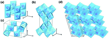 |
| | Fig. 1 Crystal structures of TiO2 polymorphs: (a) rutile; (b) anatase; (c) brookite; and (d) TiO2-B. Purple spheres represent Ti atoms, and blue octahedra represent TiO6 blocks. Oxygen atoms at the corner of the octahedra are omitted for clarity. Reproduced with permission from ref. 55. Copyright 2015, Royal Society of Chemistry. | |
Table 1 Crystal structures and electrical property parameters of four common TiO2 polymorphs
| Polymorphs |
Crystal structures |
Electrical properties |
| Space group |
Crystal system |
Unit cell (Å) |
Ref. |
Band gap (eV) |
Conductivity |
Bonding |
Ref. |
| Rutile |
P42/mnm |
Tetragonal |
a = 4.59, c = 2.96 |
21 and 55
|
3.0 indirect |
n-Type semiconductor |
Covalent bonding |
60
|
| Anatase |
I41/amd |
Tetragonal |
a = 3.79, c = 9.51 |
21 and 55
|
3.2 indirect |
n-Type semiconductor |
60
|
| Brookite |
Pbca
|
Orthorhombic |
a = 9.17, b = 5.46, c = 5.14 |
21 and 55
|
2.96 indirect |
n-Type semiconductor |
60
|
| TiO2-B |
C2/m |
Monoclinic |
a = 12.17, b = 3.74, c = 6.51, β = 107.29° |
21 and 55
|
N/A |
2.2 Crystal structures and electrical properties of MoS2
As shown in Fig. 2 and Table 2, according to previous investigations,63,64 there are three polymorphs of bulk MoS2: 1T-MoS2, 2H-MoS2, and 3R-MoS2, where the number represents the number of layers per repeat unit while the letter denotes the symmetry. 1T-MoS2 has a tetragonal unit cell that contains 1 layer with a = 0.560 nm and c = 1.838 nm.65 2H-MoS2 has a hexagonal unit cell that contains 2 layers with a = 0.315 nm, c = 1.230 nm, and γ = 120°,66 and 3R-MoS2 exhibits a rhombohedral unit cell that contains 3 layers with a = 0.317 nm, c = 1.838 nm, and γ = 120° (Fig. 2a).67 Fundamentally, the three polymorphs vary in the Mo atom coordination and the stacking orders of each layer.63,64 It is well known that a single layer of MoS2 consists of three atomic layers, where one Mo atomic layer is surrounded by double S atomic layers. Generally, there are three possible positions of the S sheets and Mo sheets, which can be labelled using the designations A, B, and C and the designations a, b, and c, respectively;68 thus, any single MoS2 layer can be described as a combination of a lowercase letter between two uppercase letters. As shown in Fig. 2b, 1T-MoS2 can be defined as AbC, as it displays octahedral coordination (Oh) of the Mo atom; namely, each S atom forms the apex of the octahedron, with the Mo atom located in its center. 2H-MoS2 and 3R-MoS2 can be described as AbA BaB AbA… and AbA BcB CaC AbA…, respectively, because both 2H-MoS2 and 3R-MoS2 represent trigonal prismatic coordination (D3h) of the Mo atom due to its d4sp hybrid orbitals.
 |
| | Fig. 2 (a) Schematics of the structural polytypes of MoS2: 2H (hexagonal symmetry, two layers per repeat unit, trigonal prismatic coordination), 3R (rhombohedral symmetry, three layers per repeat unit, trigonal prismatic coordination), and 1T (tetragonal symmetry, one layer per repeat unit, octahedral coordination). (b) Schematic crystal structures of three polytypes: 1T, 2H, and 3R. The dashed lines show how the top views and the lateral views match with each other. In the 1T and 2H polytypes, atoms of the underlying layers overlap exactly with the upper layers. However, in the 3R polytype, some atoms of the underlying layers do not overlap with the above layers; thus, they are shown faintly in the top view. Reproduced with permission from: (a) ref. 63. Copyright 2015, Nature Publishing Group; (b) ref. 64. Copyright 2015, Royal Society of Chemistry. | |
Table 2 Crystal structures and electrical property parameters of three common MoS2 polymorphs
| Polymorphs |
Crystal structures |
Electrical properties |
| Space group |
Stacking order |
Unit cell (Å) |
Ref. |
Band gap (eV) |
Conductivity |
Bonding |
Ref. |
| 1T |
P![[3 with combining macron]](https://www.rsc.org/images/entities/char_0033_0304.gif) m1 m1 |
AbC |
a = 5.60, c = 18.38 |
65
|
N/A |
Metallic |
Strong Mo–S covalent bond (about 2 eV) in single layer and weak van der Waals forces (about 200 meV) between S–Mo–S layers |
65
|
| 2H |
P63/mmc |
AbA BaB |
a = 3.15, c = 12.30, γ = 120° |
66
|
Bulk 1.29 (indirect) |
Semiconductor (P-type) |
69
|
| Monolayer 1.9 (direct) |
| 3R |
R3m |
AbA BcB CaC |
a = 3.17, c = 18.38 γ = 120° |
67
|
1.29 (indirect) |
Semiconductor (P-type) |
64
|
Among the different types, 2H-MoS2 is the most popular material in electronic, optical, and catalytic applications. Many scientists have thoroughly discussed its electronic properties. Fig. 3 shows that bulk MoS2 is an indirect semiconductor with a band gap of 1.29 eV. However, MoS2 crystals exhibit crossover from an indirect- to a direct-gap semiconductor in the monolayer limit.69 Experiments reveal a progressive confinement-induced shift in the direct-gap with decreasing number of layers, from the bulk value of 1.29 eV to over 1.90 eV. Therefore, in the monolayer, 2H-MoS2 is a direct-gap semiconductor with a band gap of 1.9 eV.69 In the 3R and 1T phases, the properties of 3R-MoS2 are similar to those of 2H-MoS2;64,70 the 1T-MoS2 phase has also attracted the attention of scientists due to its interesting properties in different areas,71–73 although the 1T-MoS2 phase has not yet been found in nature. From band structure calculations, a negative temperature coefficient and Pauli paramagnetism were observed for the electronic conductivity of 1T phase. Thus, unlike 2H phase (Fermi level in the d band gap), the 1T phase (Fermi level within the d band) is metallic. These structural and electronic distortions indicate that 1T-MoS2 is easily accessible for all electron transfer and exchange reactions.65
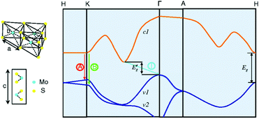 |
| | Fig. 3 Lattice structures of MoS2 in both the in- and out-plane directions and simplified band structure of bulk MoS2, showing the lowest conduction band c1 and the highest split valence bands v1 and v2. A and B are the direct-gap transitions, and I is the indirect-gap transition. E′g is the indirect-gap for the bulk, and Eg is the direct-gap for the monolayer. Reproduced with permission from ref. 69. Copyright 2010, American Physical Society. | |
3. Synthesis, structure and mechanism
Currently, increasing numbers of researchers are devoting effort to developing synthetic methods to obtain MoS2/TiO2-based composites with uniform distribution, strong interaction, and unique structures for various applications. It is generally accepted that the synthetic strategies of the composites can be roughly divided into two categories: ex situ synthetic strategies and in situ synthetic strategies. The synthetic strategies of MoS2/TiO2-based composites are illustrated in Fig. 4. We will carefully summarize recent developments as follows.
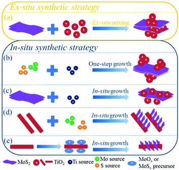 |
| | Fig. 4 Illustrations of ex situ and in situ synthetic strategies of MoS2/TiO2-based composites. | |
3.1
Ex situ synthetic strategy
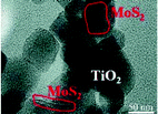
In the ex situ synthetic strategy (Fig. 4a), MoS2 and TiO2 are prepared separately in advance; then, the MoS2/TiO2 composites are synthesized by drop-casting,74 sonication assembly,75–77 impregnation,78–81 ball-milling,82,83 sol–gel,84 or hydrothermal/solvothermal assembly85–87 methods. Table 3 summarizes the various methods and parameters.
Table 3 A summary of typical MoS2/TiO2-based composites synthesized by ex situ synthetic strategies
| Composite |
SEM/TEM image |
Reaction conditions |
Ref. (year) |
| Reproduced with permission from: ref. 75. Copyright 2015, Springer; ref. 76. Copyright 2017, De Gruyte; ref. 78. Copyright 2015, Royal Society of Chemistry; ref. 79. Copyright 2015, American Chemical Society; ref. 83. Copyright 2015, Royal Society of Chemistry; ref. 82. Copyright 2016, Wiley-VCH; ref. 84. Copyright 2017, Elsevier; ref. 85. Copyright 2014, Elsevier. |
|
Sonication assembly
|
| TiO2–MoS2(1T) |
|
A mixture of a dispersion of MoS2 in ethanol and an aqueous dispersion of TiO2 was sonicated for 3 min |
75 (2015) |
| MoS2/TiO2 |
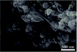
|
Mesoporous TiO2 was added to a MoS2 suspension and sonicated at a frequency of 50/60 Hz for 60 min |
76 (2017) |
| |
|
Impregnation
|
| MoS2/TiO2 mesocrystals |
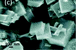
|
TiO2 mesocrystals were impregnated with exfoliated MoS2 nanosheets in Milli-Q water |
78 (2015) |
| MoS2/TiO2 nanotubes |
|
The composites were obtained by impregnation of TiO2 nanotubes with a centrifuged solution of nanosized MoS2 particles in isopropyl alcohol |
79 (2015) |
| |
|
Ball-milling
|
| TiO2/MoS2 |
|
2.0 g TiO2 was mixed with MoS2, agate balls, and 4.0 mL of absolute ethanol; then, the mixtures were ball-milled at 300 rpm for 4 h |
83 (2015) |
| Black-TiO2/MoS2/TiO2 nanosheets |

|
3.0 g TiO2 was mixed with 0.18 g MoS2, agate balls, and 5.0 mL of absolute ethanol; then, the mixtures were ball-milled at 300 rpm for 5 h |
82 (2016) |
| |
|
Sol–gel
|
| MoS2/TiO2/hollow microfibers |

|
Carboxymethyl cellulose, TiO2, and MoS2 were added to 100 mL alcohol; then, the mixture was stirred and sonicated for 2 h. The obtained paste was calcined in N2 |
84 (2017) |
| |
|
Hydrothermal/solvothermal assembly
|
| 3D MoS2/P25/graphene |

|
Degussa P25 grade and a solution of MoS2 nanosheets were added to a GO dispersion. The suspension was hydrothermally treated at 180 °C for 12 h |
85 (2014) |
The ex situ synthetic strategy has many advantages, including low cost and scalable production. However, the methods require multiple complex and time-consuming steps to prepare raw MoS2 and TiO2 materials. Moreover, it is difficult to control the preparation of the composites; MoS2 and TiO2 are randomly dispersed, with weak interactions.
3.2
In situ synthetic strategy
For the in situ synthetic strategy, the synthesis process involves ionic reactions; this results in more uniform dispersion and complex interactions compared with the ex situ synthetic strategy. Therefore, the in situ synthetic strategy is receiving an increasing amount of attention. The in situ synthetic strategy for preparing MoS2/TiO2 composites can be divided into four groups: one-step synthesis (Fig. 4b), multi-step synthesis starting with MoS2 (Fig. 4c), multi-step synthesis starting with TiO2 (Fig. 4d), and multi-step synthesis with indirect methods (Fig. 4e). We will introduce the four groups in detail as follows.
3.2.1 One-step synthesis.
As shown in Fig. 4b, the one-step synthesis method is simple and rapid. During the process, the Ti, Mo, and S sources are firstly mixed homogeneously; then, the precursor is converted into TiO2/MoS2 composites through a hydrothermal or solvothermal process.88–93Table 4 summarizes the various preparation parameters of the one-step synthesis method. The key step of this method is the preparation of the homogeneous precursor, which is composed of Ti, Mo, and S sources. The used Mo sources, such as (NH4)2MoS4, (NH4)6Mo7O24·4H2O, and (NH4)2Mo3S13·2H2O, and the S sources, such as CH4N2S and C2H5NS, are all water-soluble salts, whereas Ti sources such as Ti(OBu)4, TiOP, and TiCl4 are always water-insoluble or hydrolytic. Therefore, organic solvents such as ethanol and diethylene glycol or alkalis such as NaOH are added to stabilize the Ti, Mo, and S sources. The obtained precursors are further treated at low temperature (180 °C to 240 °C) for 12 to 24 h to prepare MoS2/TiO2 composites. In order to improve the crystallization degree of MoS2, the hydrothermal products must be annealed at a high temperature in Ar atmosphere.
Table 4 A summary of MoS2/TiO2 based composites synthesized by in situ synthetic strategies with one-step growth
| Composites |
SEM/TEM images |
Methods |
Ti sources |
Mo source/S sources |
Additives |
Conditions |
Ref. (year) |
| TiOP is titanium isopropoxide, Ti(OBu)4 is tetrabutyl titanate, NMP is N-methyl-1-pyrrolidone, IPA is isopropanol. Reproduced with permission from: ref. 88. Copyright 2013, Springer; ref. 89. Copyright 2015, Royal Society of Chemistry; ref. 90. Copyright 2016, Royal Society of Chemistry; ref. 91. Copyright 2016, Elsevier; ref. 93. Copyright 2016, Elsevier; ref. 92. Copyright 2017, Royal Society of Chemistry. |
| MoS2/TiO2 nanoparticles |

|
Solvothermal |
Ti(OBu)4 |
(NH4)2MoS4 |
Diethylene glycol |
200 °C for 12 h |
88 (2013) |
| Nano-TiO2-decorated MoS2 nanosheets |

|
Hydrothermal |
TiCl4 |
(NH4)6Mo7O24·4H2O/CH4N2S |
Ethanol |
220 °C for 24 h |
89 (2015) |
| Carbon doped TiO2–MoS2 |

|
Solvothermal |
TiOP |
(NH4)2Mo3S13·2H2O |
NMP-IPA |
180 °C for 20 h |
90 (2016) |
| TiO2/MoS2 |

|
Hydrothermal |
TiCl4 |
Na2MoO4·2H2O/C2H5NS |
NaOH |
240 °C for 24 h |
91 (2016) |
| MoS2/CdS/TiO2 nanoparticles |

|
Solvothermal |
Ti(OBu)4 |
Na2MoO4·2H2O/CH4N2S |
CdCl2·2.5H2O ethanol |
200 °C for 24 h |
93 (2016) |
| MoS2–TiO2 |

|
Hydrothermal |
(NH4)2TiF6 |
Na2MoO4·2H2O/C2H5NS |
Citric acid |
180 °C for 24 h |
92 (2017) |
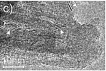
However, as with the ex situ strategy, it is still difficult to obtain uniform distribution of MoS2 and TiO2; this is because the nucleation and growth of MoS2 and TiO2 always occur simultaneously, although the interaction between MoS2 and TiO2 is stronger and more complex. For example, Sabarinathan et al.92 described the synthesis of MoS2–TiO2 mixture heterostructures via a one-step hydrothermal method in which 0.04 M Na2MoO4·2H2O, 0.08 M C2H5NS, 0.04 M citric acid, and different amounts of (NH4)2TiF6 were dissolved in 50 mL of deionized water and further maintained at 180 °C for 24 h. As shown in Fig. 5, the TEM images present a random distribution of MoS2. The HR-TEM images show that the MoS2 and TiO2 in all the samples contact each other through good interfaces, demonstrating strong interaction between the two components. However, the SEM images show that the TiO2 agglomerates into increasingly large particles from S2 to S6 as the content of the Ti source increases, suggesting that TiO2 was nonuniformly dispersed in the random MoS2. Therefore, despite the urgent need, it is still difficult to prepare uniformly distributed MoS2/TiO2 composite materials through a one-step synthesis strategy.
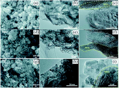 |
| | Fig. 5 (a, d, and g) FESEM, (b, e, and h) TEM and (c, f, and i) HRTEM images of samples S2, S4, and S6. S2, S4, and S6 contain 0.0015 M, 0.0050 M, and 0.015 M (NH4)2TiF6, respectively. Reproduced with permission from ref. 92. Copyright 2017, Royal Society of Chemistry. | |
3.2.2 Multi-step synthesis: MoS2 first.
In this strategy, as shown in Fig. 4c, the MoS2 is prepared in advance as the substrate for in situ growth of TiO2; the resulting composites are TiO2-coated MoS2 heterostructures. This strategy requires one additional step compared with the one-step synthesis strategy, namely advance preparation of MoS2; thus, it appears to be more complicated. However, actually, the multi-step method involves obviously different mechanisms of nucleation and growth because the MoS2 acts as a template and also provides active sites for TiO2 nucleation in this strategy. The synthetic methods of MoS2 have been summarized systematically in many profound reviews to date;48–50 thus, we only highlight the methods of decorating TiO2 onto the surface of the MoS2 substrate here. A great variety of methods for preparing pure TiO2 materials have been reported.13,15–18,21 Particularly, decoration of TiO2 onto the surface of MoS2 is always performed at low temperature and under oxygen-deficit conditions because the MoS2 substrate has excellent chemical stability in inert conditions but is prone to oxidization in oxygen-rich and relatively high temperature conditions. In this section, the reported synthetic strategy includes hydrothermal/solvothermal75,94–99 and atomic layer deposition100 methods. Table 5 summarizes the detailed reaction parameters and conditions.
Table 5 A summary of MoS2/TiO2 based composites synthesized by in situ synthetic strategies where the MoS2 substrate is prepared in advance and then decorated with TiO2
| Composites |
SEM/TEM images |
Methods |
Ti sources |
Additives |
Conditions |
Ref. (year) |
| Ti(OBu)4 is tetrabutyl titanate, DEG is diethylene glycol, DMF is N,N-dimethylformamide, GO is graphene oxide, and P123 is PEG-PPG-PEG triblock copolymer. Reproduced with permission from: ref. 97. Copyright 2012, American Chemical Society; ref. 75. Copyright 2015, Springer; ref. 96. Copyright 2016, Institute of Physics Publishing; ref. 98. Copyright 2016, Elsevier; ref. 100. Copyright 2017, American Chemical Society. |
| TiO2/MoS2/graphene |

|
Hydrothermal |
Ti(OBu)4 |
GO, ethanol |
180 °C for 10 h |
97 (2012) |
| TiO2–MoS2(2H) |

|
Hydrothermal |
Ti(OBu)4 |
Ethanol, DMF |
200 °C for 20 h |
75 (2015) |
| TiO2/MoS2 nanosheets |
|
Hydrothermal |
Ti(OBu)4 |
DEG, HF |
180 °C for 12 h |
96 (2016) |
| TiO2/g-C3N4/MoS2 |

|
Solvothermal |
TiCl4 |
g-C3N4, ethanol, glycerol, (NaPO3)6 |
140 °C for 3 h |
98 (2016) |
| MoS2-1 nm–TiO2 |
|
Atomic layer deposition |
TiCl4 |
N/A |
75 °C at the speed of ∼0.8 Å per cycle |
100 (2017) |
3.2.2.1 Hydrothermal and solvothermal methods.
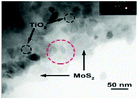
The hydrothermal and solvothermal methods are conducted at low temperatures (≤200 °C) in a closed system with aqueous solution or organic solvent above ambient temperature and pressure. These methods have been widely used to decorate TiO2 onto the surface of MoS2.75,94–99 The morphology, size, and content of TiO2 in the obtained composites can be easily adjusted by controlling the reaction conditions. However, the morphologies of the reported composites mostly depend on their corresponding MoS2 substrates. The bulk MoS2 templates result in TiO2 agglomeration and undispersed MoS2/TiO2 composites due to the insufficient growth sites of MoS2.94,95 Conversely, few-layered and well-dispersed MoS2 substrates possess large specific surface areas with abundant active sites for TiO2 decoration, leading to nano-TiO2-coated MoS2 nanosheet composites with homogeneous distribution and strong interaction.75,96 For example, Bai et al. prepared few-layered MoS2 nanosheets through a chemical exfoliation method; the MoS2 and Ti source suspensions were then obtained in additional steps. Finally, the TiO2–MoS2(2H) hybrid was synthesized by in situ growth of TiO2 nanocrystals on MoS2 nanosheets through a hydrothermal process.75 However, prefabricated MoS2 nanosheets must always be dispersed in a particular solution to avoid agglomeration; namely, additional operations such as washing, centrifugation and drying are required to purify the MoS2 nanosheets, which complicates the process. To address these situations, many researchers have introduced stable substrates with large specific surface areas, such as graphene oxide (GO)97 and g-C3N4,98,99 to prepare MoS2/GO and MoS2/g-C3N4 composites in advance instead of pure MoS2 nanosheets. The MoS2/GO and MoS2/g-C3N4 nanosheets are readily prepared by hydrothermal methods and collected by filtration and drying. The thus-obtained powders can be readily used in the next hydrothermal or solvothermal process. Moreover, the large specific surface areas of GO and g-C3N4 are beneficial to improve the dispersity of MoS2 and TiO2, along with other unique properties. For example, Xiang et al. firstly reported the synthesis of TiO2 nanoparticles on a layered MoS2/graphene hybrid photocatalyst by a two-step hydrothermal process.97 The TEM image (Table 5) of the resulting TiO2/MoS2/graphene composite shows that the MoS2/graphene nanosheets serve as a novel support that is uniformly decorated with TiO2 nanoparticles. Moreover, the superior electron mobility of the introduced graphene can greatly improve the photocatalytic performance. Therefore, these multi-component composites with controllable synthesis, homogeneous distribution, and unique properties are very important.
3.2.2.2 Atomic layer deposition method.
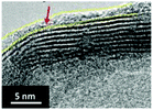
Atomic layer deposition (ALD) has been widely used to prepare nano-TiO2 covering layers. Recently, Ren and co-workers100 firstly described the preparation of ultrathin TiO2-modified MoS2 nanosheet arrays by an ALD process at 75 °C in which TiCl4 and H2O were used as the Ti and O sources, respectively. The thickness of the TiO2 layer was effectively controlled by controlling the number of depositions. It can be clearly seen that the morphology of TiO2-modified MoS2 nanosheet arrays are closely related to those of the MoS2 template. The method enables the preparation of uniform TiO2 particles or continuous coating layers on the MoS2 surface. However, this method is still limited by low yields due to the low deposition rate and limited working thickness.
3.2.3 Multi-step synthesis: TiO2 first.
As shown in Fig. 4d, in this strategy, TiO2 with various morphologies and properties is synthesized as a template for in situ growth of MoS2; the resulting composites are MoS2-coated TiO2 heterostructures. This strategy is similar to that described above. The conceptual difference between the two strategies is the sequence of preparation of TiO2 and MoS2 in the MoS2/TiO2 composites. However, the TiO2 substrate has better chemical stability and a greater variety of morphologies compared with the MoS2 substrate. Therefore, MoS2/TiO2 composites can be prepared under more varied conditions by this strategy, and their morphologies can be readily controlled by adjusting the TiO2 substrate. As a result, this strategy is more widely used for preparing MoS2/TiO2-based composites. As many extensive reviews have summarized the synthetic methods of TiO2 in detail,13,15–18,21 we will not summarize the synthesis of TiO2 substrate here; instead, we will focus on the methods of decorating MoS2 onto the surface of TiO2. Although many reviews48–50 have summarized the synthetic methods of MoS2, the TiO2 substrate/template creates new challenges and possibilities under limited conditions. This synthetic strategy has involved hydrothermal or solvothermal techniques,101–146 chemical bath deposition,147 and photo-deposition148,149 methods to date. Table 6 summarizes the various preparation methods of MoS2/TiO2-based composites where the TiO2 substrate was prepared in advance followed by decoration with MoS2.
Table 6 A summary of typical MoS2/TiO2 based composites synthesized by in situ synthetic strategies where the TiO2 substrate is prepared in advance and then decorated with MoS2
| Composites |
SEM/TEM images |
Methods |
TiO2 surface states |
Mo sources/S sources |
Additives |
Conditions |
Ref. |
| DMF is dimethyl formamide, DMAC is dimethylacetamide, CTAB is cetyltrimethyl ammonium bromide, P123 is PEO-PPO-PEO, PEG = poly(ethylene glycol), and PPG = poly(propylene glycol). Ref. 102, 122, 127, and 132. Copyright 2014, Royal Society of Chemistry; ref. 126 and 144. Copyright 2015, Royal Society of Chemistry; ref. 123 and 131. Copyright 2016, Royal Society of Chemistry; ref. 113, 116, 136, and 141. Copyright 2017, Royal Society of Chemistry; ref. 147. Copyright 2017, Hindawi; ref. 143. Copyright 2017, Springer; ref. 148. Copyright 2004, American Chemical Society; ref. 138. Copyright 2015, American Chemical Society; ref. 101. Copyright 2013, Wiley-VCH; ref. 107, 121, and 134. Copyright 2016, Wiley-VCH; ref. 118 and 120. Copyright 2017, Wiley-VCH; ref. 103, 115, and 137. Copyright 2015, Elsevier; ref. 105, 109, 124, 128, 129, 130, and 139. Copyright 2016, Elsevier; ref. 111, 115, 117, 145, and 149. Copyright 2017, Elsevier. |
|
3.2.3.1 Hydrothermal and solvothermal methods
|
|
(a) TiO
2
surface state: rough TiO
2
|
| TiO2@MoS2 nanobelts |

|
Hydrothermal |
Rough |
Na2MoO4·2H2O/C2H5NS |
N/A |
200 °C for 24 h |
101 (2013) |
| TiO2@MoS2 nanobelt |

|
Hydrothermal |
Rough |
Na2MoO4·2H2O/CH4N2S |
N/A |
220 °C for 24 h |
102 (2014) |
| TiO2@MoS2 nanofiber |

|
Hydrothermal |
Rough |
Na2MoO4·2H2O/C2H5NS |
N/A |
220 °C for 24 h |
103 (2015) |
| MoS2/TiO2 nanofiber |
|
Hydrothermal |
Rough |
Na2MoO4·2H2O/L-cysteine |
N/A |
180 °C for 24 h |
105 (2016) |
| TiO2@MoS2 nanotube array |

|
Hydrothermal |
Rough |
Na2MoO4·2H2O/C2H5NS |
N/A |
200 °C for 24 h |
107 (2016) |
| TiO2/MoS2 hollow sphere |

|
Hydrothermal |
Rough |
Na2MoO4·2H2O/C2H5NS |
N/A |
220 °C for 24 h |
109 (2016) |
| MoS2–TiO2 nanorod |

|
Hydrothermal |
Rough |
Na2MoO4·2H2O/CH4N2S |
N/A |
220 °C for 24 h |
111 (2017) |
| MoS2@hydrogenated-TiO2 nanobelt |

|
Hydrothermal |
Rough |
Na2MoO4·2H2O/L-cysteine |
N/A |
200 °C for 24 h |
113 (2017) |
| MoS2@TiO2 nanotube array |

|
Hydrothermal |
Rough |
Na2MoO4·2H2O/C2H5NS |
N/A |
220 °C for 24 h |
115 (2017) |
| MoS2/TiO2 cylinder |

|
Hydrothermal |
Rough |
Na2MoO4/CH4N2S |
N/A |
200 °C for 24 h |
116 (2017) |
| TiO2@MoS2 nanofiber |

|
Hydrothermal |
Rough |
Na2MoO4·2H2O/C2H5NS |
N/A |
220 °C for 24 h |
117 (2017) |
| TiO2@distorted 1T-MoS2 nanofibers |

|
Hydrothermal |
Rough |
Na2MoO4·2H2O/C2H5NS |
N/A |
220 °C for 24 h |
118 (2017) |
|
(b) TiO
2
surface state: intermediate layer
|
| TiO2@carbon@MoS2 nanotubes |

|
Hydrothermal |
TiO2@C prepared in advance |
Na2MoO4·2H2O/CH4N2S |
Glucose |
200 °C for 24 h |
120 (2017) |
|
(c) TiO
2
surface state: lattice match
|
| TiO2@MoS2 nano-onions |

|
Hydrothermal |
Ti0.87O2 precursor prepared instead[Editor31] |
Na2MoO4·2H2O/C2H5NS |
N/A |
200 °C for 24 h |
121 (2016) |
|
(d) Reaction parameter: acidic conditions
|
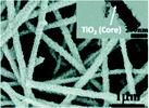
| MoS2-TiO2 nanowires |
|
Hydrothermal |
Rough |
MoO3/KSCN |
HCl |
240 °C for 24 h |
122 (2014) |
| TiO2-B/MoS2 nanowire arrays |

|
Hydrothermal |
Rough |
MoO3/C2H5NS |
HCl |
220 °C for 20 h |
123 (2016) |
| MoS2/TiO2/Si nanowires |

|
Hydrothermal |
Rough |
Na2MoO4·2H2O/L-cysteine |
HCl |
180 °C for 12 h |
124 (2016) |
|
(e) Reaction parameter: organic binder
|
| MoS2@TiO2 nanotubes |

|
Solvothermal |
Rough |
Na2MoO4·2H2O/CH4N2S |
Glucose |
200 °C for 24 h |
127 (2014) |
| TiO2@MoS2 nanowires |

|
Hydrothermal |
Rough |
Na2MoO4·2H2O/CH4N2S |
Glucose |
200 °C for 24 h |
126 (2015) |
| Carbon-coated TiO2@MoS2 nanosheets |

|
Hydrothermal |
Rough |
Na2MoO4·2H2O/CH4N2S |
Glucose |
200 °C for 24 h |
128 (2016) |
| TiO2@MoS2/C nanosheet arrays |

|
Hydrothermal |
Rough |
Na2MoO4·2H2O/CH4N2S |
Glucose |
200 °C for 22 h |
129 (2016) |
|
(f) Reaction parameter: surfactant
|
| TiO2@MoS2 microspheres |

|
Hydrothermal |
Smooth |
Na2MoO4·2H2O/CH4N2S |
CTAB |
180 °C for 36 h |
130 (2016) |
| MoS2/TiO2/Ti nanosheet arrays |

|
Solvothermal |
Smooth |
Na2MoO4·2H2O/CH4N2S |
P123 |
230 °C for 24 h |
131 (2016) |
|
(g) Reaction parameter: organic solvent
|
| MoS2/r-GO/P25 |

|
Solvothermal |
Two-phase |
Na2MoO4·2H2O/C2H5NS |
GO, DMAC |
150 °C for 10 h |
132 (2014) |
| TiO2/MoS2 nanospheres |

|
Solvothermal |
Rough with mesopores |
(NH4)2MoS4 |
DMF |
180 °C for 24 h |
134 (2016) |
| MoS2@TiO2 microspheres |

|
Solvothermal |
Rough with mesopores |
Na2MoO4·2H2O/L-cysteine |
Ethanol |
220 °C for 24 h |
136 (2017) |
|
(h) TiO
2
nanosheets with exposed {001} facets
|
| MoS2/TiO2{001} nanosheets |

|
Hydrothermal |
F-ion |
Na2MoO4·2H2O/C2H5NS |
N/A |
210 °C for 24 h |
137 (2015) |
| 2D–2D MoS2/TiO2 nanosheets |

|
Hydrothermal |
F-ion |
Na2MoO4·2H2O/CH4N2S |
N/A |
200 °C for 24 h |
138 (2015) |
| MoS2/TiO2(001) nanosheets |

|
Hydrothermal |
F-ion |
Na2MoO4·2H2O/CH4N2S |
N/A |
200 °C for 24 h |
139 (2016) |
| MoS2/TiO2 nanosheets |

|
Hydrothermal |
F-ion |
Na2MoO4·2H2O/CH4N2S |
N/A |
180 °C for 24 h |
141 (2017) |
| MoS2/TiO2 nanosheets |

|
Hydrothermal |
F-ion |
Na2MoO4·2H2O/C2H5NS |
N/A |
200 °C for 24 h |
143 (2017) |
|
(i) TiO
2
nanosheets with exposed {001} facets + organic binder |
| MoS2@TiO2 nanosheets |

|
Hydrothermal |
F-ion |
Na2MoO4·2H2O/CH4N2S |
Glucose |
200 °C for 24 h |
144 (2015) |
| G/TiO2@C/MoS2 nanosheets |

|
Hydrothermal |
F-ion with GO |
Na2MoO4·2H2O/CH4N2S |
Glucose |
200 °C for 24 h |
145 (2017) |
| |
|
3.2.3.2 Chemical bath deposition method
|
| MoS2/TiO2 film |

|
Chemical bath deposition |
Rough |
(NH4)6Mo7O24·4H2O/CH4N2S |
N2H4·H2O |
80 °C for 45 min |
147 (2017) |
| |
|
3.2.3.3 Photoinduced deposition method
|
| MoS2/P25 |
N/A |
Photodeposition |
Two-phase |
(NH4)2MoS4 |
N2, N2H4·H2O |
Irradiated with a 300 W Xe lamp |
148 (2004) |
| MoS2/CdS-TiO2 |

|
Photodeposition |
Rough |
(NH4)2MoS4 |
N2 |
Irradiated with a 300 W Xe lamp |
149 (2017) |
3.2.3.1 Hydrothermal and solvothermal methods.
Hydrothermal and solvothermal methods are bottom-up strategies to prepare MoS2 nanosheets using Mo ions and S ions. Meanwhile, the TiO2 substrate/template shows excellent chemical stability in these conditions. Therefore, hydrothermal and solvothermal methods are the most commonly used to synthesize MoS2 on the surface of TiO2. Generally, as shown in Fig. 6, this method contains two steps: nucleation and growth. Of these, the nucleation step plays a crucial role. The added TiO2 in the reaction solution acts as the substrate or template for MoS2 nucleation, which is called heterogeneous nucleation.150 It is found that the surface states (crystal lattice and surface) of the TiO2 substrate/template have strong effects on the heterogeneous nucleation of MoS2 on the TiO2 substrate or template. After successful nucleation, the crystallization of MoS2 hetero-epitaxy occurs on the TiO2 substrate/template. The size and density of these MoS2 nanosheets can be readily controlled by adjusting the reaction parameters, such as growth time, growth temperature, initial reactant concentration, pH value, and additives. Since 2013, when Zhou et al.101 first synthesized a few-layered MoS2 nanosheet-coated TiO2 nanobelt composite via a hydrothermal method at 200 °C for 24 h using Na2MoO4·2H2O as the Mo source and C2H5NS as the S source, a large number of MoS2/TiO2-based composites have been reported to be fabricated using this method. There has been an upsurge of research interest in the controlled synthesis of MoS2-coated TiO2 composites with various morphologies.101–142 As mentioned above, the hydrothermal or solvothermal controllable synthesis of MoS2/TiO2-based composites are determined by two aspects: TiO2 surface states and reaction parameters. Various MoS2/TiO2-based composites have been synthesized by adjusting controllable factors, which will be extensively discussed below. The TiO2 surface states directly influence nucleation and growth. Among these, a small lattice mismatch (<5%) between two compounds with similar crystal structures can promote epitaxial nucleation and growth.150 In general, there are four different crystallographic forms of TiO2 (Table 1) and three different crystallographic forms of MoS2 (Table 2). Among these forms, anatase TiO2![[thin space (1/6-em)]](https://www.rsc.org/images/entities/char_2009.gif) 79 and 2H-MoS2
79 and 2H-MoS2![[thin space (1/6-em)]](https://www.rsc.org/images/entities/char_2009.gif) 64 are the most stable and common crystal phases under hydrothermal synthesis conditions. For anatase TiO2, the natural and artificial crystal exposes the most stable (101) plane (rectangular cell: 5.48 Å × 3.78 Å).121 Meanwhile, anatase TiO2 nanosheets with exposed (001) planes (hexagonal cell: 3.79 Å × 3.79 Å) have gained considerable attention and great research interest due to their novel properties.151–155 2H-MoS2, which is a typical layered structure material, shows a dominant (002) surface (hexagonal cell: 2.41 Å × 2.41 Å).121 The unit structures are shown in Fig. 7. The lattice of the 2H-MoS2 (002) plane is elongated by 36.2% and 5.6% to match the anatase (101) plane and (001) plane, respectively. The large lattice mismatch between MoS2 and TiO2, especially common anatase TiO2 with exposed (101) planes, impedes the epitaxial nucleation and growth of MoS2 nanosheets on the TiO2 substrate/template. Meanwhile, the TiO2 substrate is always negatively charged, and the commonly used Mo sources are Mo-containing anions such as MoO42− and MoS42−; thus, the charge incompatibility between negatively charged TiO2 and Mo-containing anions causes them to repel each other. As a result, the formed MoS2 nanosheets tend to assemble into microspheres instead of coating the TiO2 surface (Fig. 8). To address this issue, many studies have explored the abovementioned two aspects: TiO2 surface states and reaction parameters.
64 are the most stable and common crystal phases under hydrothermal synthesis conditions. For anatase TiO2, the natural and artificial crystal exposes the most stable (101) plane (rectangular cell: 5.48 Å × 3.78 Å).121 Meanwhile, anatase TiO2 nanosheets with exposed (001) planes (hexagonal cell: 3.79 Å × 3.79 Å) have gained considerable attention and great research interest due to their novel properties.151–155 2H-MoS2, which is a typical layered structure material, shows a dominant (002) surface (hexagonal cell: 2.41 Å × 2.41 Å).121 The unit structures are shown in Fig. 7. The lattice of the 2H-MoS2 (002) plane is elongated by 36.2% and 5.6% to match the anatase (101) plane and (001) plane, respectively. The large lattice mismatch between MoS2 and TiO2, especially common anatase TiO2 with exposed (101) planes, impedes the epitaxial nucleation and growth of MoS2 nanosheets on the TiO2 substrate/template. Meanwhile, the TiO2 substrate is always negatively charged, and the commonly used Mo sources are Mo-containing anions such as MoO42− and MoS42−; thus, the charge incompatibility between negatively charged TiO2 and Mo-containing anions causes them to repel each other. As a result, the formed MoS2 nanosheets tend to assemble into microspheres instead of coating the TiO2 surface (Fig. 8). To address this issue, many studies have explored the abovementioned two aspects: TiO2 surface states and reaction parameters.
 |
| | Fig. 6 Schematic of the nucleation and growth of MoS2 nanosheets on a TiO2 template. Reproduced with permission from ref. 103. Copyright 2015, Elsevier. | |
 |
| | Fig. 7 Top views of projected structures of (a) 2H-MoS2 (002) plane, (b) anatase TiO2 (101) plane and (c) anatase TiO2 (001) plane. Reproduced with permission from: (a, b) ref. 121. Copyright 2016, Wiley-VCH; (c) ref. 155. Copyright 2014, American Chemical Society. | |
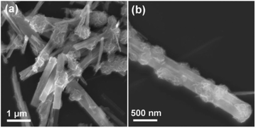 |
| | Fig. 8 Growth of MoS2 nanosheets on the smooth surface of untreated TiO2 nanobelts. Reproduced with permission from ref. 101. Copyright 2013, Wiley-VCH. | |
3.2.3.1 (a) TiO
2
surface state: rough TiO
2
. To modify the surface state of TiO2, the surface roughness of the substrate/template is a key driving force of the nucleation. Therefore, many studies have introduced rough TiO2 as the substrate to decorate MoS2 nanosheets, as shown in Table 6. For example, Zhou and co-workers101 added an acid treatment process prior to the calcination of H2Ti3O7 nanobelts to obtain a rough TiO2 surface, providing high energy nucleation sites for the nucleation and growth of MoS2 nanosheets. As a result, few-layered MoS2 nanosheet-coated TiO2 nanobelt heterostructures were successfully prepared (see Table 6). Liu et al.103 obtained porous TiO2 nanofibers after removal of PVP by calcination of the electrospinning precursor; MoS2 nanosheets were grown on the resulting porous TiO2 nanofibers via a simple hydrothermal process (see Table 6). This modification strategy has been widely explored and studied;101–119 it is key to obtain TiO2 with sufficient surface roughness to overcome the obstacle of lattice mismatch between TiO2 and MoS2. The high surface roughness of TiO2 can facilitate the growth of MoS2 nanoparticles to serve as seeds for later growth of MoS2 nanosheets.150 However, the processes for obtaining high surface roughness are time-consuming and complex.
3.2.3.1 (b) TiO
2
surface state: intermediate layer. In addition, introducing an intermediate layer between TiO2 and MoS2 is an effective method for the growth of MoS2 nanosheets on the surface of Ti2O. The intermediate layer should serve as a bonding interface to create strong adhesion between MoS2 and TiO2. Generally, carbon materials, especially amorphous carbon with abundant functional groups, can readily coat TiO2![[thin space (1/6-em)]](https://www.rsc.org/images/entities/char_2009.gif) 156–158 and support MoS2
156–158 and support MoS2![[thin space (1/6-em)]](https://www.rsc.org/images/entities/char_2009.gif) 159–161 with strong chemical bonds. Therefore, amorphous carbon can be used as an ideal intermediate layer material in this process. Recently, as shown in Fig. 9a, Wang and co-workers120 reported the synthesis of hierarchical tubular structures by sequential coating of a nitrogen-doped carbon (NC) layer and MoS2 nanosheets on TiO2 nanotubes (designated as TiO2@NC@MoS2). According to Fig. 9b and c, we can observe that the NC layer tightly coats the TiO2 surface in TiO2@NC. The prefabricated TiO2@NC is then used to grow MoS2 nanosheets. After the hydrothermal and calcination processes, as shown in Fig. 9d and e, the NC intermediate layer acts as a bonding interface to maintain good contact between the TiO2 nanotubes and MoS2 nanosheets in the obtained TiO2@NC@MoS2; this is a very stable architecture. The NC intermediate layer can also increase electrical conductivity, which is beneficial to rechargeable batteries. In contrast, the carbon intermediate layer may impede the delivery of holes between MoS2 and TiO2, which is detrimental to photocatalytic applications. Therefore, the introduced carbon intermediate layer requires careful design according to specific applications. This modification strategy is facile and effective. However, it requires multiple steps; thus, it is time-consuming and complex.
159–161 with strong chemical bonds. Therefore, amorphous carbon can be used as an ideal intermediate layer material in this process. Recently, as shown in Fig. 9a, Wang and co-workers120 reported the synthesis of hierarchical tubular structures by sequential coating of a nitrogen-doped carbon (NC) layer and MoS2 nanosheets on TiO2 nanotubes (designated as TiO2@NC@MoS2). According to Fig. 9b and c, we can observe that the NC layer tightly coats the TiO2 surface in TiO2@NC. The prefabricated TiO2@NC is then used to grow MoS2 nanosheets. After the hydrothermal and calcination processes, as shown in Fig. 9d and e, the NC intermediate layer acts as a bonding interface to maintain good contact between the TiO2 nanotubes and MoS2 nanosheets in the obtained TiO2@NC@MoS2; this is a very stable architecture. The NC intermediate layer can also increase electrical conductivity, which is beneficial to rechargeable batteries. In contrast, the carbon intermediate layer may impede the delivery of holes between MoS2 and TiO2, which is detrimental to photocatalytic applications. Therefore, the introduced carbon intermediate layer requires careful design according to specific applications. This modification strategy is facile and effective. However, it requires multiple steps; thus, it is time-consuming and complex.
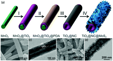 |
| | Fig. 9 (a) Schematic of the synthesis process of TiO2@NC@MoS2 tubular nanostructures. (I) TiO2 coating, (II) PDA coating, (III) annealing in N2 and acid etching, and (IV) growth of MoS2 nanosheets. (b, d) FESEM and (c, e) TEM images of (b, c) TiO2@NC nanotubes and (d, e) annealed TiO2@NC@MoS2 nanotubes. Reproduced with permission from ref. 120. Copyright 2017, Wiley-VCH. | |
3.2.3.1 (c) TiO
2
surface state: lattice match. Although the above two modification strategies can effectively be used to grow MoS2 nanosheets on the surface of TiO2, core–shell architectures cannot be successfully prepared. Because the significant lattice mismatch between TiO2 and MoS2 remains, a dendritic/dumbbell-like morphology is more likely to form by the above two modification strategies.101–120 In order to prepare core–shell nanostructures with high-quality interfaces, the as-exposed TiO2 surface should be well designed and adjusted. Recently, Dai et al.121 used unilamellar Ti0.87O2 nanosheets as a starting material and subsequently epitaxially grew MoS2 on TiO2. The formation of these core–shell nano-onions is attributed to an amorphous layer-induced hetero-growth mechanism. As shown in Fig. 10, during the hydrothermal process, the Ti0.87O2 nanosheets recrystallized and transformed into distorted anatase nanocrystals.121 The abundant Ti vacancies may lead to the rearrangement of Ti and O atoms during the phase transformation process, thus forming an amorphous layer outside the anatase nucleus. This amorphous layer significantly facilitates the nucleation of MoS2 on the anatase nanocrystals. Subsequently, MoS2 grains continue to grow epitaxially on the amorphous surface of the anatase nanoparticles. The amorphous layer at the anatase TiO2/MoS2 interface gradually disappears with prolonged hydrothermal reaction time. Finally, TiO2@MoS2 nano-onions with a high-quality interface are obtained (see Table 6) despite the large lattice mismatch between TiO2 and MoS2.121 The obtained TiO2@MoS2 nano-onions show superior structural stability when they are evaluated as LIB anodes.
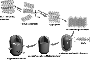 |
| | Fig. 10 Schematic of the proposed formation process for TiO2@MoS2 nano-onions. Reproduced with permission from ref. 121. Copyright 2016, Wiley-VCH. | |
3.2.3.1 (d) Reaction parameter: acidic conditions. Apart from the TiO2 surface states, the reaction parameters are also important for the growth of MoS2. Among these, the pH value is an important factor in hydrothermal processes. When slightly soluble MoOx is used as the Mo source, the MoOx converts to MoS2 by itself and does not coat onto TiO2. Therefore, some researchers have added inorganic acid to the solution to convert MoOx to Mo ions upon hydrothermal treatment; the MoS2 then nucleates and grows on the rough TiO2 surface.122,123 TiO2 and MoS2 show high structural stability under weakly acidic conditions. Moreover, the TiO2 surface can provide more high-energy nucleation sites in acidic conditions upon hydrothermal treatment.101,102 Therefore, weakly acidic conditions can further facilitate the nucleation and growth of MoS2 on the surface of TiO2, leading to MoS2-coated TiO2 hierarchical structures with uniform coverage.124,125
3.2.3.1 (e) Reaction parameters: organic binder. In addition, the additive also plays a key role in the hydrothermal process. Glucose has been widely used as an organic binder in the preparation of uniform MoS2-based composites due to its abundant hydroxyl groups.162–164 Herein, some researchers used glucose to promote the growth of MoS2 nanosheets on the surface of TiO2.126–129 For example, Li and co-workers126 prepared TiO2 nanowires with rough surfaces (Fig. 11a) as a substrate; then, the rough TiO2 nanowires were added to two solutions for a hydrothermal reaction, where one solution contained Na2MoO4 and CN2H4S and the other contained excess glucose. The two solutions were transferred into stainless steel autoclaves and maintained at 200 °C for 24 h. After the hydrothermal reaction, as shown in Fig. 11b, although the TiO2 possessed a rough surface, few MoS2 nanosheets were coated onto the surface of TiO2 without the assistance of glucose. Most of the MoS2 sheets aggregated into thick flakes, probably due to insufficient roughness. Upon the addition of glucose, the MoS2 coated uniformly on the surface of TiO2 with smaller size and thickness, as shown in Fig. 11c. Therefore, glucose promoted the growth of MoS2 nanosheets on the surface of TiO2 with uniform coverage. In addition, MoS2 nanosheets can also grow on rough anatase TiO2 nanosheets with exposed (001) faces with the assistance of glucose.128 We have explored the reaction mechanism of glucose-assistance in our previous work.128 As shown in Fig. 12a, the glucose molecules can be absorbed on the surface of rough ultrathin TiO2 (UT-TiO2) and simultaneously tightly adsorb MoO42−via their abundant hydroxyl groups. Then, the glucose is carbonated on the surface of UT-TiO2, and MoS2 nuclei form on the carbon surface during the hydrothermal process in a relatively short reaction time of 8 h (Fig. 12b). MoS2 grows homogeneously and finally forms few-layered 2D interconnected MoS2 networks in 24 h (Fig. 12c). In summary, both a certain degree of roughness of TiO2 and glucose are crucial for the formation of uniform TiO2@MoS2 nanocomposites. The rough surface of TiO2 can provide accessible active sites for the adsorption of glucose molecules. The adsorbed glucose can adsorb large Mo ions tightly via its abundant hydroxyl groups. Therefore, the glucose acts as a binder to promote the growth of MoS2 nanosheets on TiO2 with uniform coverage.
 |
| | Fig. 11 FESEM images of (a) rough TiO2 and TiO2–MoS2 composites (b) without and (c) with the addition of glucose. Reproduced with permission from ref. 126. Copyright 2015, Royal Society of Chemistry. | |
 |
| | Fig. 12 Schematic of the synthesis of UT-TiO2/C@DR-MoS2. (a) Homogeneous solution containing UT-TiO2, C6H12O6, Na2MoO4 and CN2H4S. (b) UT-TiO2/C/MoS2-8 h and (c) UT-TiO2/C@DR-MoS2 obtained with hydrothermal reaction times of 8 h and 24 h, respectively. Reproduced with permission from ref. 128. Copyright 2016, Elsevier. | |
3.2.3.1 (f) Reaction paraments: surfactant. The surfactant has an important impact on the interface state of the solution system; thus, it can effectively control the nucleation and growth. In general, the most commonly used Mo sources in hydrothermal and solvothermal processes are Na2MoO4·2H2O, (NH4)6Mo7O24·4H2O, and (NH4)2MoS4 inorganic salts (see Table 6). They form Mo-containing anions when they are dissolved in water. Therefore, a cationic surfactant is helpful to increase the interaction between TiO2 and negatively charged Mo-containing species. Among these, cetyltrimethyl ammonium bromide (CTAB) is a well-known cationic surfactant which has also been widely used in the preparation of MoS2-based composites by hydrothermal methods.165–167 Recently, Xu et al.130 added 0.5 wt% CTAB surfactant to a reaction solution containing Na2MoO4·2H2O, C2H5NS, and smooth TiO2 microspheres. As shown in Fig. 13, the CTAB is adsorbed on the negatively charged TiO2 surface due to electrostatic interactions. Due to the adsorption of CTA+ on the surface of TiO2, the surface is positively charged and can further absorb MoO42− anions without repelling them. During the hydrothermal process, the MoO42− is reduced to MoS2 nanosheets in situ by H2S released by C2H5NS on the TiO2 microspheres. In conclusion, cationic surfactants can effectively aid MoS2 nucleation and growth on the TiO2 surface to form TiO2@MoS2 composites. Moreover, Zhou and co-workers131 reported vertically aligned MoS2 nanosheets on the surface of TiO2 with the assistance of nonionic surfactant P123. Therefore, the additition of surfactant is beneficial for controlling the morphology of MoS2/TiO2 composites; this requires further exploration and research.
 |
| | Fig. 13 Schematic of the synthesis process of core–shell TiO2@MoS2 composites. Reproduced with permission from ref. 130. Copyright 2016, Elsevier. | |
3.2.3.1 (g) Reaction parameters: organic solvent. The solvent is also important in the preparation of MoS2/TiO2 composites. Generally, the solvent dissolves the Mo and S sources and TiO2 substrate to prepare a homogeneous precursor solution. Water is widely used as a solvent to dissolve soluble inorganic salts. Meanwhile, it is also necessary to add organic solvent to dissolve some organic Mo and S sources or inhibit hydrolysis under certain conditions.132–136 For example, Zhao et al.133 added ethanol and oleic acid to water to inhibit MoCl5 hydrolysis, and the uniform solution ensures the successful preparation of TiO2@MoS2 composites (see Table 6). Liu and co-workers135 used sulfur powder, which cannot be dissolved in water, as a S source. Thus, the authors chose ethanol and octylamine as solvents to dissolve the sulfur power. As a result, MoS2/TiO2 composites were successfully prepared.
3.2.3.1 (h) TiO
2
nanosheets with exposed {001} facets. 2D anatase TiO2 nanosheets with exposed {001} facets have attracted especially great interest in photocatalysis and rechargeable batteries due to their unique properties. Therefore, many researchers have devoted much effort to using 2D TiO2 nanosheets as a substrate to grow 2D MoS2 nanosheets.137–143 Herein, we also summarized the preparation strategy and mechanism of 2D–2D MoS2/TiO2 nanosheets. Generally, TiO2 nanosheets are prepared by employing a fluorine morphology controlling agent; thus, the obtained exposed TiO2 {001} facets are covered by ![[triple bond, length as m-dash]](https://www.rsc.org/images/entities/char_e002.gif) Ti–F bonds. This unique surface state has an important impact on the nucleation and growth of the MoS2 nanosheets. The
Ti–F bonds. This unique surface state has an important impact on the nucleation and growth of the MoS2 nanosheets. The ![[triple bond, length as m-dash]](https://www.rsc.org/images/entities/char_e002.gif) Ti–F bonds on the surface are unstable during hydrothermal treatment,168 and they tend to be replaced by hydroxyl groups (eqn (1)).169 Therefore, the obtained
Ti–F bonds on the surface are unstable during hydrothermal treatment,168 and they tend to be replaced by hydroxyl groups (eqn (1)).169 Therefore, the obtained ![[triple bond, length as m-dash]](https://www.rsc.org/images/entities/char_e002.gif) Ti–OH bonds can absorb anionic Mo sources, such as MoO42− and MoS42−,170 which are then reduced in situ by the S source to form 2D–2D MoS2/TiO2 nanosheets. The TEM images in Table 6 show the 2D–2D structures of the obtained nanosheets.
Ti–OH bonds can absorb anionic Mo sources, such as MoO42− and MoS42−,170 which are then reduced in situ by the S source to form 2D–2D MoS2/TiO2 nanosheets. The TEM images in Table 6 show the 2D–2D structures of the obtained nanosheets.
| | ![[triple bond, length as m-dash]](https://www.rsc.org/images/entities/char_e002.gif) Ti–F + H2O → Ti–F + H2O → ![[triple bond, length as m-dash]](https://www.rsc.org/images/entities/char_e002.gif) Ti–OH + H+ + F˙− Ti–OH + H+ + F˙− | (1) |
However, the number of transformed hydroxyl groups on the surface of the TiO2 nanosheets is limited by the specific surface area of TiO2. Generally, the reported specific surface area of TiO2 nanosheets is around 50 m2 g−1,137–143 which is significantly lower than that of the carbon substrate. Therefore, only small amounts of MoS2 nanosheets can be loaded on the TiO2 nanosheet surface (see Table 6). The loading amounts of MoS2 are 0.73 wt%, 2 wt%, 5 at%, 1 wt%, 0.5 wt%, 5 at% and 5 wt% in ref. 137, 138, 139, 140, 141, 142, and 143, respectively. The small amounts of MoS2 nanosheets in MoS2/TiO2 nanosheets severely limit their application in rechargeable batteries because the MoS2 is necessary to provide high capacity.
3.2.3.1 (i) TiO
2
nanosheets with exposed {001} facets + organic binder. In order to increase the amount of MoS2 in 2D–2D MoS2/TiO2 nanosheets, in our previous studies, we firstly introduced the organic binder glucose to promote the nucleation and growth of MoS2 on the surface of TiO2 nanosheets.144,145 As shown in Fig. 14, the flourinated-TiO2 (F-TiO2) nanosheets can capture glucose molecules with electrostatic interactions. The adsorbed glucose with abundant hydroxyl groups can then absorb a large amount of MoO42−.170 During the hydrothermal process, the ![[triple bond, length as m-dash]](https://www.rsc.org/images/entities/char_e002.gif) Ti–F bonds are removed, the glucose is carbonized in situ on the TiO2 surface, and the MoS2 nanosheets are formed in situ on the amorphous carbon. Finally, 3D few-layered MoS2-coated TiO2 nanosheet (3D FL-MoS2@TiO2) core–shell nanocomposites were prepared with a relatively large ratio of 47 wt% for MoS2. This stable core–shell TiO2@MoS2 composite with 47 wt% MoS2 shows excellent electrochemical performance as a LIB anode. We have also explored the relationship between glucose addition and the prepared structure.145 The result shows that an appropriate amount of glucose is essential for obtaining ideal composites in which the surface of TiO2 is entirely covered with the grown MoS2 shell.
Ti–F bonds are removed, the glucose is carbonized in situ on the TiO2 surface, and the MoS2 nanosheets are formed in situ on the amorphous carbon. Finally, 3D few-layered MoS2-coated TiO2 nanosheet (3D FL-MoS2@TiO2) core–shell nanocomposites were prepared with a relatively large ratio of 47 wt% for MoS2. This stable core–shell TiO2@MoS2 composite with 47 wt% MoS2 shows excellent electrochemical performance as a LIB anode. We have also explored the relationship between glucose addition and the prepared structure.145 The result shows that an appropriate amount of glucose is essential for obtaining ideal composites in which the surface of TiO2 is entirely covered with the grown MoS2 shell.
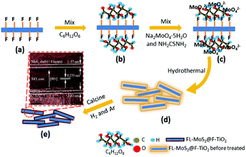 |
| | Fig. 14 Schematic of the fabrication of 3D FL-MoS2@TiO2 using F-TiO2 as template and C6H12O6 as binder. (a) F-TiO2. (b) C6H12O6-coated F-TiO2. (c) C6H12O6-coated F-TiO2 adsorbed by MoO42−. (d) Hydrothermal 3D FL-MoS2@TiO2 before thermal treatment. (e) 3D FL-MoS2@TiO2. Reproduced with permission from ref. 144. Copyright 2015, Royal Society of Chemistry. | |
Moreover, we expanded this strategy to prepare core-double shell carbon-supported MoS2 nanosheet-coated P25 (P25@C@MoS2) composite using fluorinated P25 and glucose binder.146
In summary, hydrothermal and solvothermal methods with TiO2 as a substrate/template are effective and excellent methods for preparing core–shell TiO2@MoS2 composites. The synthetic process and structure can be carefully controlled by adjusting the TiO2 surface states and reaction parameters for different applications. Moreover, the shapes and dimensionalities of the resulting MoS2/TiO2-based composites are determined by those of the TiO2 substrate/template. Various morphologies, such as nanowires, nanofibers, nanobelts, nanotubes, nano-onions, cylinders, flowers and micro-spheres, have been synthesized to date (see Table 6).
3.2.3.2 Chemical bath deposition method.
Compared with hydrothermal and solvothermal methods, chemical bath deposition is a common low-temperature aqueous technique for depositing thin MoS2/TiO2 films with large areas.171 Recently, Phung and co-workers147 used chemical bath deposition to prepare MoS2/TiO2 heterostructure thin films. Firstly, TiO2 thin films were prepared on glass substrates using a dip-coating process. Secondly, the prepared TiO2 thin films were immersed into a solution containing (NH4)6Mo7O24·4H2O, CH4N2S, and N2H4·H2O. The bath was maintained at 80 °C for different deposition times. Finally, MoS2 was well deposited on the surface of the TiO2 films to fabricate MoS2/TiO2 heterostructure films.
3.2.3.3 Photoinduced deposition method.
Photodeposition is also a simple and economical technique for depositing inorganic materials.172 In 2004, Ho et al.148 firstly used photoinduced deposition to prepare nanosized MoS2-decorated TiO2 composites. As shown in Fig. 15, a 300 W high-pressure mercury lamp was used as a UV light source, and hydrazine was added to react with the positively charged holes. The electrons photogenerated in situ converted the MoS42− anions to MoS2 directly on the surface of the TiO2 particles under UV light irradiation. Notably, it is worth pointing out that MoS2 exhibits quantum-sized nanoclusters due to the mild reaction environment. The quantum-sized MoS2 nanoclusters can significantly improve the visible light activity of photocatalysis. Moreover, this method can be extended to prepare WS2/TiO2 composites using WS42− anions.148 The reaction mechanism of this method is based on photocatalysis.
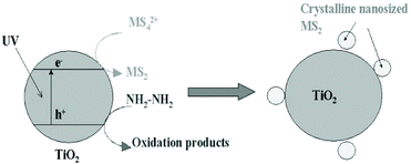 |
| | Fig. 15 Proposed model of in situ photoinduced fabrication of MS2 (M = W and Mo)-sensitized TiO2. Reproduced with permission from ref. 148. Copyright 2004, American Chemical Society. | |
3.2.4 Multi-step synthesis: indirect method.
In the above in situ synthesis methods starting with TiO2, the MoS2 directly nucleates and then grows on the TiO2 surface. The synthesis process is mostly controlled by the nucleation. However, the large lattice mismatch between MoS2 and TiO2 impedes the nucleation; this is considered to be the most major issue of this technique. In order to address this issue, some researchers have proposed using indirect methods to avoid direct nucleation of MoS2 on the TiO2 substrate. The methods can be subdivided into two groups: preparing the MoOx/TiO2 composite in advance followed by sulfuration,173–176 and preparing the MoSx/TiO2 composite in advance followed by reduction.177,178 MoOx and MoSx probably have low lattice mismatch with MoS2; therefore, MoOx/TiO2 and MoSx/TiO2 can be prepared more readily. More interestingly, the indirect method shows a unique growth mechanism compared with direct methods. Table 7 summarizes the synthesis parameters.
Table 7 A summary of MoS2/TiO2-based composites synthesized by in situ synthetic strategies where MoOx/TiO2 or MoSx/TiO2 precursors are prepared in advance and then transformed into MoS2/TiO2 composites
| Composite |
SEM/TEM image |
Methods |
TiO2 surface states |
Mo source/S sourceb |
Additiveb |
Conditionsb |
Ref. (year) |
|
Represents the first step.
Represents the second step.
|
|
3.2.4.1 MoO
x
/TiO
2
precursors first
|
| MoS2–TiO2 nanofibers |

|
Two-step: impregnationa, thermal sulfurationb |
MoOx/TiO2 precursor prepared in advance |
N/A/H2S |
N/A |
500 °C for 2 h |
173 (2015) |
| MoS2/TiO2 nanotube arrays |

|
Two-step: sputteringa, thermal sulfurationb |
MoO3/TiO2 precursor prepared in advance |
N/A/H2S |
N/A |
500 °C for 30 min |
174 (2016) |
| TiO2/MoS2(E) nanowires |

|
Two-step: impregnationa, thermal sulfurationb |
MoO2/TiO2 precursor prepared in advance |
N/A/S |
N/A |
400 °C for 1 h under vacuum |
175 (2016) |
| Flower-like MoS2/TiO2 |

|
Two-step: hydrothermala, hydrothermal sulfurationb |
MoO2/TiO2 precursor prepared in advance |
N/A/CH4N2S |
N/A |
200 °C for 48 h |
176 (2017) |
| |
|
3.2.4.2 MoS
x
/TiO
2
precursors first
|
| Nano-MoS2/TiO2 |

|
Two-step: chemical bath depositiona, thermal reductionb |
MoS3/TiO2 precursor prepared in advance |
N/A |
H2 |
450 °C for 30 min |
177 (2010) |
| MoS2/P25 |

|
Two-step: depositiona, thermal reductionb |
MoSx/TiO2 precursor prepared in advance |
N/A |
H2 |
350 °C |
178 (2017) |
3.2.4.1 MoOx/TiO2 precursors first.
In the direct methods described above, the MoS2/TiO2 composites are prepared by reaction between Mo ions and S ions on TiO2 substrates. However, for the indirect method, as shown in Fig. 4e, the MoS2/TiO2 composites are formed by the transformation of solid MoOx/TiO2 precursors. The solid transformation mechanism in the indirect method is obviously different from the growth mechanism with ionic reactions in the direct method. For example, He et al.175 reported a unique heterostructure with MoS2 standing on TiO2 along its edges (named TiO2/MoS2(E)). As shown in Fig. 16, the prefabricated TiO2/MoO2 composite was sulfurized in a chemical deposition system. During the sulfurizing process, the sulfurization began on the surface of MoO2 and then diffused to the deep interior. The sulfur diffusion occurred more rapidly parallel to the basal plane because of the weak interaction between the MoS2 layers.179 Therefore, the growth direction is the same as the sulfur diffusion direction, from the surface of MoO2 to the interface between MoO2 and TiO2. The interface between MoO2 and TiO2 is the last area to be sulfurized; thus, the lattice match rule is avoided. Finally, connection of the MoS2 nanoplates with TiO2via edges was achieved for the first time. Moreover, compared to the direct methods described above, the effects of surface energy on the growth process of MoS2 are suppressed. Although the indirect method requires multiple steps, the unique formation mechanism is interesting and powerful and can offer a new synthesis strategy for fine structures and interface designs.
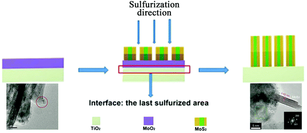 |
| | Fig. 16 Schematic of the sulfurization process. The inset TEM images correspond to TiO2/MoO2 and TiO2/MoS2(E)3%, respectively. Reproduced with permission from ref. 175. Copyright 2016, Wiley-VCH. | |
4. Applications and enhancement strategies
4.1 Photocatalysis
MoS2/TiO2 composites have been extensively studied as photocatalysts for photocatalytic degradation, hydrogen evolution, and CO2 reduction. In general, TiO2 and MoS2 serve as catalyst and cocatalyst, respectively. As shown in Fig. 17, under light irradiation, TiO2 is excited to generate electron–hole pairs with photon energy higher than its band gap energy (Eg). Unfortunately, the excited electrons (e−) and holes (h+) are unstable and can easily recombine. The loaded cocatalyst MoS2 can effectively accept photogenerated charge carriers to reduce recombination. Moreover, the MoS2 cocatalyst can provide large catalytically active sites for photocatalytic progress. The separated holes can be used as oxidants for degradation of organic pollutants, while the separated electrons can be used as reductants for hydrogen evolution and CO2 reduction (Fig. 17).
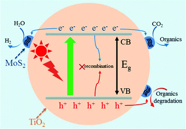 |
| | Fig. 17 Schematic of organics degradation, photocatalytic hydrogen evolution, and CO2 photoreduction over a TiO2 photocatalyst loaded with MoS2 cocatalyst. VB is the valance band, and CB is the conduction band. | |
4.1.1 Photocatalytic degradation.
Degradation of pollutants in water using solar energy is an attractive technology for environmental protection. MoS2/TiO2 composites are widely used for the photocatalytic degradation of organic pollutants, such as RhB,77,84,104,105,107,124,132,134,137 MB,81,86,87,92,117,139,143,147,148 MO,82,85,94,95,98,106,114 direct green 676 4-ATP,90 Rs,93 and phenol.109 According to previous reports,86,92,148 the generated electron–hole pairs (eqn (2)) are formed under light irradiation. Then, the photogenerated holes react with water molecules on the surface of the composites, forming hydroxyl radicals (˙OH) (eqn (3)). The holes and obtained ˙OH can oxidize the organic molecules directly on the surface of the composites. In addition, the generated electrons can react with O2 molecules in air to form superoxide radical anions (˙O2−) (eqn (4)); then, ˙O2− can transform into ˙OH (eqn (5)–(7)) via complex and selective steps that are difficult to achieve. Therefore, the photogenerated holes and resulting ˙OH are the main oxidants for the degradation of organic pollutants. Table 8 summarizes the reported MoS2/TiO2-based photocatalysts for pollutant degradation.| | | MoS2/TiO2 + hv → MoS2 (h+)/TiO2 (e−) | (2) |
| | | ˙O2− + H2O → {˙HO2} + OH− | (5) |
| | | ˙HO2 + H2O → H2O2 + {˙OH} | (6) |
Table 8 A summary of MoS2/TiO2-based photocatalysts for pollutant degradation
| Materials/(MoS2 wt%) |
Pollutant content/(mg L−1) |
Light source |
Activity |
Photoactivity enhancement |
Ref. (year) |
| RHB is rhodamine B, MB is methylene blue, MO is methyl orange, 4-ATP is 4-aminothiophenol, Rs is resorcinol, TC is tetracycline, DP is degradation percentage, K is rate constant, Kapp is average rate constant. |
|
Pollutant: RhB
|
| MoS2/TiO2{001} nanosheets/0.73% |
10 |
300 W Xe lamp λ > 400 nm |
DP of over 98.3% in 100 min |
1.35 × >TiO2 |
137 (2015) |
| TiO2–MoS2 nanobelts/40% |
10 |
500 W Xe lamp visible light |
K 0.0239 min−1 |
4.78 × >TiO2 |
104 (2015) |
| MoS2/r-GO/P25 |
10 |
150 W Xe lamp simulated sunlight |
DP of over 80% in 80 min |
4 × >P25 |
132 (2015) |
| MoS2/P25/0.1% |
10 |
Simulated sunlight |
K 0.221 min−1 |
1.5 × >P25 |
77 (2016) |
| MoS2/TiO2 nanofibers |
10 |
50 W mercury lamp λ = 313 nm 10 mW cm−2 |
DP of 98.2% in 30 min |
7.01 × >TiO2 |
105 (2016) |
| TiO2@MoS2 nanotube arrays |
10 |
230 W mercury lamp λ = 365 nm |
DP of 85.3% in 120 min |
1.14 × >TiO2 |
107 (2016) |
| MoS2/TiO2/Si nanowires |
5 × 10⁻⁶ M |
Visible fiber lamp λ 420 to 700 nm 0.5 W cm−2 |
DP of 82% in 180 min |
2.9 × >TiO2/Si |
124 (2016) |
| TiO2/MoS2 nanospheres |
5 |
500 W Xe lamp visible light |
DP of over 97.8% in 180 min |
1.9 × >TiO2 |
134 (2016) |
| MoS2/TiO2/hollow microfibers |
20 |
500 W halogen lamp λ > 390 nm |
DP of 38% in 20 min |
N/A |
84 (2017) |
| |
|
Pollutant: MB
|
| MoS2/P25 |
8 |
300 W Xe lamp λ 400 to 660 nm |
DP of ∼40% in 4 h |
N/A |
148 (2004) |
| MoS2–TiO2/7.1% |
5 ppm |
UV lamp |
K 0.034 min−1 |
2.13 × >P25 |
87 (2011) |
|
Z-Scheme g-C3N4/TiO2/MoS2/0.5% |
10 |
500 W Xe lamp 280 to 800 nm |
DP of 99.54% in 45 min |
N/A |
81 (2016) |
| TiO2-RGO/MoS2 |
10 |
Natural sunlight |
DP of ∼100% in 100 min |
N/A |
86 (2016) |
| MoS2/TiO2(001) nanosheets/5% |
4 × 10⁻⁵ M |
250 W mercury lamp UV-vis light |
K 0.04797 min−1 |
3.4 × >TiO2 |
139 (2016) |
| MoS2–TiO2 |
5 |
400 W Xe lamp visible light |
DP of 99.33% in 12 min |
1.75 × >P25 |
92 (2017) |
| Ag3PO4/TiO2@MoS2 nanofibers/3.5% |
2.5 |
300 W Xe lamp visible light |
DP of ∼95% in 16 min |
2.5 × >Ag3PO4 |
117 (2017) |
| MoS2/TiO2 nanosheets/4.36% |
1 × 10⁻⁵ M |
300 W Xe lamp λ > 420 nm |
DP of over 83.26% in 30 min |
1.4 × >TiO2 |
143 (2017) |
| MoS2/TiO2 film |
10 ppm |
Visible light |
DP of 60% in 150 min |
N/A |
147 (2017) |
| |
|
Pollutant: MO
|
| 3D MoS2/P25/graphene/0.5% |
20 |
300 W Hg lamp UV light |
DP of 100% in 15 min |
∼1.4 × >P25 |
85 (2014) |
| TiO2/MoS2@zeolite |
20 |
500 W Xe lamp visible light |
K
app 2.304 h−1 |
2.65 × >TiO2@zeolite |
94 (2015) |
| TiO2/MoS2 |
20 |
500 W Xe lamp λ > 464 nm |
DP of 97% in 60 min |
3.46 × >P25 |
95 (2015) |
| Black-TiO2/MoS2/TiO2 nanosheets |
10 |
300 W Xe lamp λ > 420 nm |
K 0.01788 min−1 |
17.5 × >TiO2 |
82 (2016) |
| TiO2/g-C3N4/MoS2 |
20 |
500 W Xe lamp simulated sunlight |
DP of 90% in 60 min |
3.11 × >TiO2 |
98 (2016) |
| MoS2/TiO2 nanobelts/5% |
20 |
300 W mercury lamp λ = 356 nm/350 W Xe lamp λ > 420 nm |
DP of ∼100% in 15 min/∼100% in 120 min |
1.08/50 × >TiO2 |
106 (2016) |
| Nitrogen doped-TiO2−x@MoS2 |
10 |
300 W Xe lamp λ > 420 nm |
DP of 91.8% in 120 min |
21.3 × >TiO2 |
114 (2017) |
| |
|
Pollutant: direct green 6
|
| MoS2/TiO2/0.3% |
60 |
Sunlight 0.75 W m−2 |
DP of >95% in 3 days |
2.2 × >TiO2 |
76 (2017) |
| |
|
Pollutant: 4-ATP
|
| Carbon-doped TiO2-MoS2/0.7% |
10 |
84 W light source λ > 420 nm |
DP of 40% in 60 min |
2.22 × >TiO2 |
90 (2016) |
| |
|
Pollutant: Rs
|
| MoS2/CdS/TiO2 nanoparticles |
50 |
500 W Xe lamp UV-vis light |
DP of 21.19% in 60 min third cycle |
1.25 × >CdS/TiO2 |
93 (2016) |
| |
|
Pollutant: phenol
|
| TiO2/MoS2 hollow spheres |
10 |
300 W Xe lamp λ > 420 nm |
DP of 78% in 150 min |
N/A |
109 (2016) |
4.1.2 Photocatalytic hydrogen evolution.
The photocatalytic hydrogen reduction using MoS2/TiO2-based photocatalysts is a sustainable and economical technique for addressing the energy crisis. The photogenerated electrons on the surface of the MoS2 cocatalyst can reduce H2O molecules to H2 directly. Since Kanda and co-workers180 first prepared MoS2/TiO2 composites through in situ photoinduced deposition as photocatalysts for hydrogen evolution, many researchers have devoted effort to exploring low-cost and high-activity MoS2/TiO2-based photocalysts.75,78,82,83,88,97,99,101,103,106,108,114,118,119,122,138,140,149,174,175,180 The synthetic methods have been summarized in section 3. Similar to photocatalytic degradation, the photocatalytic hydrogen evolution activity of MoS2/TiO2 composites depends on their light harvesting, charge carrier separation and migration, and catalytically active sites. A variety of strategies have been reported to increase photocatalytic hydrogen evolution performance, especially in the last three years. Examples include (i) MoS2 engineering for promoting photocatalytic activity; (ii) interface engineering and graphene cocatalyst loading for improving charge carrier separation and migration efficiencies; (iii) visible light activity catalysis loading, photosensitizer loading and element doping for broadening the light absorption range. The strategies for improving the utilization efficiency of solar energy will be discussed in detail below. The recent MoS2/TiO2-based photocatalysts for photocatalytic hydrogen evolution are summarized in Table 9. Under visible light, the best photocatalytic hydrogen production achieved to date among reported MoS2/TiO2-based composites is 16![[thin space (1/6-em)]](https://www.rsc.org/images/entities/char_2009.gif) 700 μmol g−1 h−1 in the presence of 5 vol% TEOA as a sacrificial agent.122
700 μmol g−1 h−1 in the presence of 5 vol% TEOA as a sacrificial agent.122
Table 9 A summary of MoS2/TiO2 based photocatalysts for photocatalytic hydrogen evolution
| Materials/(MoS2 wt%) |
Sacrificial agents |
Light sources |
Photoactivity (μmol g−1 h−1) |
Ref. (year) |
| TEOA is triethanolamine, FI is fluorescein, ZnTCPP is Zn(II)-5,10,15,20-tetrakis (4-carboxyphenyl) porphyrin, and EY is Eosin Y. |
| MoS2/TiO2 |
5 vol% formic acid |
300 W Xe lamp λ > 300 nm |
73 |
180 (2011) |
| TiO2/MoS2/graphene/0.5% |
25 vol% ethanol/H2O |
350 W Xe lamp λ = 365 nm 20 mW cm−2 |
2066.3 |
97 (2012) |
| TiO2@MoS2 nanobelts/50% |
0.35 M Na2S and 0.25 M Na2SO3 solution |
300 W Xe lamp λ 280 to 700 nm 600 mW cm−2 |
1600 |
101 (2013) |
| MoS2/TiO2 nanoparticles/1.0% |
20 vol% methanol/H2O |
300 W Xe lamp simulated sunlight 100 mW cm−2 |
120 |
88 (2013) |
| EY-MoS2-TiO2 nanowires |
5 vol% TEOA/H2O |
300 W Xe lamp λ > 420 nm |
16![[thin space (1/6-em)]](https://www.rsc.org/images/entities/char_2009.gif) 700 700 |
122 (2014) |
| TiO2–MoS2(2H) |
25 vol% methanol/H2O |
300 W Xe lamp λ < 400 nm 2.7 mW cm−2 |
∼175 |
75 (2015) |
| TiO2–MoS2(1T) |
25 vol% methanol/H2O |
300 W Xe lamp λ < 400 nm 2.7 mW cm−2 |
∼2000 |
| MoS2/TiO2 mesocrystals/10% |
10 vol% lactic acid/H2O |
UV-LED source 100 mW cm−2 |
550 |
78 (2015) |
| TiO2/MoS2/4.0% |
15 vol% methanol/H2O |
300 W Xe lamp 250 to 380 nm |
150.7 μmol h−1 |
83 (2015) |
| TiO2@MoS2 nanofibers/60% |
0.35 M Na2S and 0.25 M Na2SO3 solution |
300 W Xe lamp 168 mW cm−2 visible light/UV-vis |
490/16![[thin space (1/6-em)]](https://www.rsc.org/images/entities/char_2009.gif) 800 800 |
103 (2015) |
| ZnTCPP–MoS2/P25 nanoparticles/1.0% |
0.2 M TEOA |
300 W Xe lamp λ > 420 nm |
10.2 μmol h−1 |
119 (2015) |
| Black-TiO2/MoS2/TiO2 nanosheets |
20 vol% methanol/H2O |
300 W Xe lamp λ > 420 nm |
560 |
82 (2016) |
| 2D–2D MoS2/TiO2 nanosheets/0.5% |
10 vol% methanol/H2O |
300 W Xe lamp |
2145 |
138 (2016) |
| MoS2/boron doped-TiO2 nanosheets/1.0% |
33 vol% methanol/H2O |
300 W Xe lamp λ > 400 nm 150 mW cm−2 |
500 |
140 (2016) |
| g-C3N4/MoS2/TiO2/0.9% |
33 vol% methanol/H2O |
300 W Xe lamp λ > 400 nm |
125 μmol h−1 |
99 (2016) |
| MoS2/TiO2 nanotube arrays |
50 vol% methanol/H2O |
AM 1.5 solar 100 mW cm−2 |
∼10 μL h−1 |
174 (2016) |
| TiO2/MoS2(E) nanowires/0.5% |
20 vol% ethanol/H2O |
300 W Xe lamp UV light |
4300 |
175 (2016) |
| MoS2/TiO2 nanobelts/5% |
20 vol% methanol/H2O |
300 W Xe lamp simulated sunlight 100 mW cm−2 |
75 |
106 (2016) |
| FI-flower-like MoS2@TiO2/14.6% |
7.5 vol% TEOA/acetone-H2O |
Visible light |
10![[thin space (1/6-em)]](https://www.rsc.org/images/entities/char_2009.gif) 046 046 |
108 (2016) |
| Nitrogen doped-TiO2−x@MoS2 |
20 vol% methanol/H2O |
AM 1.5 solar power system |
1882 |
114 (2017) |
| EY-TiO2@distorted 1T-MoS2 nanofibers |
15 vol% TEOA/H2O |
300 W Xe lamp λ 420 to 780 nm 168 mW cm−2 |
∼10![[thin space (1/6-em)]](https://www.rsc.org/images/entities/char_2009.gif) 000 000 |
118 (2017) |
| MoS2/CdS-TiO2/1% |
10 vol% lactic acid |
300 W Xe lamp λ > 420 nm |
280 μmol h−1 |
149 (2017) |
4.1.3 Photocatalytic CO2 reduction.
In addition to photocatalytic hydrogen evolution, the photoreduction of CO2 into organic fuel sources based on MoS2/TiO2 photocatalysis shows great potential applications in both reducing greenhouse effects and addressing the energy crisis. Although MoS2/TiO2-based composites have been widely used in photocatalytic degradation and hydrogen evolution, only a few reports have focused on the photocatalytic reduction of CO2. This is because CO2 reduction is a multi-electron transfer and multi-step process. Recently, Tu et al.141 firstly reported the use of MoS2/TiO2 nanosheets as photocatalysts for CO2 reduction to CH3OH. The reaction pathway of CH3OH generation in aqueous solution is CO2 → HCOOH → HCHO → CH3OH.181 Photocatalytic measurements confirmed that the MoS2 cocatalyst can effectively promote charge carrier separation and provide catalytically active sites. The active sites of Mo-terminated edges on MoS2 benefit the stabilization of the intermediate products (CHxOy) (Fig. 18). MoS2/TiO2 nanosheets with 0.5 wt% MoS2 photocatalyst achieved the highest CO2 reduction activity of 10.6 μmol g−1 h−1 under UV-vis light; this is 1.9 times higher than that of pure TiO2 nanosheets (Fig. 18). Moreover, its activity is also higher than those of TiO2 nanosheet photocatalysts loaded with 0.5 wt% Pt and Au, demonstrating that MoS2 exhibits better and more selective photocatalytic reduction of CO2 to CH3OH than Pt and Au noble cocatalysts. However, the reported CO2 reduction activity is still low; this requires further improvement and optimization.
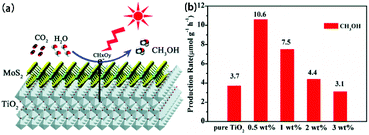 |
| | Fig. 18 (a) Schematic of the charge separation and transfer in a MoS2/TiO2 nanosheet composite for the photoreduction of CO2 to CH3OH. (b) Comparison of the photocatalytic activity of pure TiO2 nanosheets and MoS2/TiO2 hybrid nanosheets with different MoS2 amounts for CO2 photoreduction. Reproduced with permission from ref. 141. Copyright 2017, Royal Society of Chemistry. | |
4.1.4 Strategies for photocatalytic activity enhancement.
4.1.4.1 MoS2 engineering.
MoS2 cocatalysts offer catalytically active sites for direct photocatalytic progress. Therefore, it is important to optimize MoS2 with more catalytically active sites. MoS2 has two main phases (2H phase and 1T phase) in practical research. Generally, MoS2 exhibits the stable 2H phase in MoS2/TiO2-based composites. For 2H-MoS2, the active sites are located along the edges, while the basal surface of MoS2 is catalytically inert.182 Moreover, 2H-MoS2 is a p-type semiconductor and thus has low charge carrier transport mobility. Therefore, these disadvantages of 2H-MoS2 strongly limit its photocatalytic activity as a co-catalyst. In order to address these issues, engineering of MoS2 has been widely researched. MoS2 engineering in MoS2/TiO2-based composites mainly involves three methods. First, some researchers prepared small-sized 2H-MoS2 in the in-plane direction to increase the exposed edge sites and reduce the charge carrier transport pathway.77,79,80,87,104,132,148,177,180 As a result, the small-sized MoS2/TiO2 composites show significantly improved photocatalytic activity. The dispersion of small-sized MoS2 and the interaction between MoS2 and TiO2 should be well considered when using this modified method. Second, the surface defects of 2H-MoS2 can provide additional active edge sites; however, they can also decrease the charge transfer kinetics. In order to disrupt the inverse relationship between MoS2 surface defects and charge transfer rate, some researchers chose to dope MoS2 together with defect engineering. The results demonstrated that oxygen-doped defective MoS2 shows increased active edge sites and charge transfer rates compared with pure MoS2.183–185 Therefore, the photocatalytic activity of MoS2 and its composites were significantly improved. However, there are no related reports of combining defect engineering with element doping in MoS2/TiO2-based composites; this topic is worthy of exploration. Third, some researchers have used 1T-MoS2 instead of 2H-MoS2 in MoS2/TiO2-based composites, as 1T-MoS2 can not only offer active sites on its edge sites and basal surface, but also possesses excellent charge carrier transfer ability.74,75,118 Moreover, unlike the case of 2H-MoS2, the photogenerated electrons can participate directly in the reduction reaction on 1T-MoS2 near the TiO2, with no need to migrate to the far 2H-MoS2 active edge sites (Fig. 19). This further decreases the chance of charge carrier recombination due to the greatly shortened transfer length of the electrons. As a result, the TiO2–MoS2(1T) sample exhibited 2 and ∼8 times higher RhB degradation and hydrogen evolution than the TiO2–MoS2(2H) sample, respectively, in the work of Bai et al. (Fig. 19).75 Notably, 1T-MoS2 is unstable under ambient conditions; it can readily change into 2H-MoS2 during hydrothermal processes and low-temperature calcination.78 Therefore, researchers always prepare 1T-MoS2 in advance and then mix it with TiO2 through ex situ strategies under mild conditions.74,75 Thus, the interface contact between MoS2 and TiO2 is weak, which is harmful to charge carrier transfer. Recently, Wang and co-workers118 prepared TiO2@distorted 1T-MoS2 nanofibers through transformation of TiO2@2H-MoS2 that was fabricated by an in situ hydrothermal method; 1T-MoS2 contacted TiO2via a good interface. The stability of 1T-MoS2 should be carefully considered when preparing and using 1T-MoS2/TiO2-based composites.
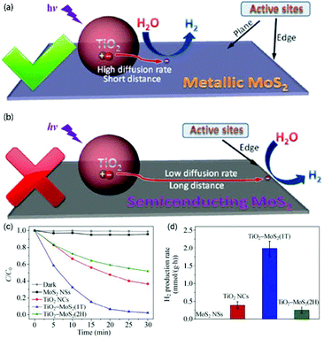 |
| | Fig. 19 Schematic of the charge-transfer behavior and H2 evolution active sites for (a) 1T-MoS2 and (b) 2H-MoS2. (c) Photocatalytic degradation curves and (d) photocatalytic average rates of hydrogen production of RhB with MoS2 NSs, TiO2 NCs, TiO2–MoS2(1T), and TiO2–MoS2(2H) as catalysts under UV light irradiation. Reproduced with permission from ref. 75. Copyright 2015, Springer. | |
![[thin space (1/6-em)]](https://www.rsc.org/images/entities/char_2009.gif) 800 and 490 μmol g−1 h−1 under UV-vis and visible light, respectively.
800 and 490 μmol g−1 h−1 under UV-vis and visible light, respectively.
Moreover, the interface contact between standing MoS2 and TiO2 requires further exploration and research. Recently, He et al.175 developed a new strategy to control the contact of MoS2 nanoplates with the TiO2 surface along the MoS2 edges (TiO2/MoS2(E)) (Fig. 20a), which is obviously different from the contact type in traditional TiO2/MoS2(B) composites (Fig. 20b). The designed photocatalyst showed excellent electrical contact and an optimized electron transfer pathway along the basal planes (Fig. 20c). As a result, TiO2/MoS2(E) with 3 wt% MoS2 exhibited dramatically enhanced photocatalytic activity of 4300 μmol g−1 h−1 under UV light, which is over 8 times that of TiO2/MoS2(E) with the same MoS2 content (Fig. 20d).
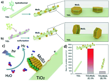 |
| | Fig. 20 Schematic of the preparation of TiO2/MoS2 composites. (a) Wet chemical method for preparing TiO2/MoO2(B) composite, where MoS2 nanoplates contact the TiO2 surface along (B) the basal planes; (b) CVD strategy to prepare TiO2/MoS2(E) composite, where MoS2 nanoplates contact the TiO2 surface along the edges (E); (c) schematic of the photoexcited electron transport pathway on TiO2/MoS2(E); (d) comparison of H2 evolution rates on TiO2, TiO2/MoS2(E)3%, and TiO2/MoS2(B)3%. Reproduced with permission from ref. 175. Copyright 2016, Wiley-VCH. | |
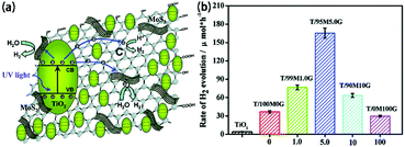 |
| | Fig. 21 (a) Schematic of the charge transfer in TiO2/MG composites. (b) Photocatalytic H2 evolution of TiO2/MG composites. Photocatalytic H2 production experiments were performed in 25% (v/v) ethanol/water solutions under UV irradiation using the photocatalyst TiO2/MG composites with different MoS2 and graphene contents in the MG hybrid as cocatalysts. Reproduced with permission from ref. 97. Copyright 2012, American Chemical Society. | |
 |
| | Fig. 22 (a) Absorption spectra of TiO2, MoS2/TiO2 and ZnTCPP-MoS2/TiO2. (b) Proposed mechanism for visible-light-induced hydrogen production over ZnTCPP–MoS2/TiO2, S: ZnTCPP, D: TEOA; ES+/S* = ES+/S − E0–0. Reproduced with permission from ref. 119. Copyright 2016, Elsevier. | |
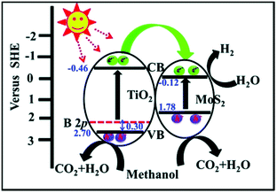 |
| | Fig. 23 Schematic of the energy band structure of the MoS2/B-TiO2 heterostructure and the proposed charge transfer mechanism under visible light irradiation. Reproduced with permission from ref. 140. Copyright 2016, Royal Society of Chemistry. | |
4.2 Rechargeable batteries
4.2.1 Lithium-ion batteries.
Lithium-ion batteries (LIBs) are regarded as green and promising power sources due to their long cycle life and high-energy densities. MoS2/TiO2 composites are promising anode materials for LIBs owing to their combined advantages of high specific capacity and strong structural stability. In these composites, TiO2 stores Li+via a typical intercalation mechanism, while MoS2 shows different storage mechanisms by controlling the cut-off voltage range. Table 10 summarizes the LIB performance of reported MoS2/TiO2-based anode materials.
Table 10 A summary of the LIB performance of MoS2/TiO2-based anode materials
| Materials |
MoS2 and TiO2 weight contents |
Voltage range |
Capacities (mA h g−1) at different current densities (A g−1) (after 100 cycles) |
Capacities (mA h g−1) at different current densities (A g−1) |
Ref. (year) |
|
4.2.1.1 TiO
2
as an anode material for LIBs
|
| MoS2–TiO2 nanofibers |
6%, 94% |
1 to 3 V |
124 at 6 (1000) |
188, 177, 120 at 1, 2, 40 |
173 (2015) |
| |
|
4.2.1.2 TiO
2
as a supplemental material in LIBs
|
| TiO2@MoS2 nanobelts |
50.1%, 49.9% |
0.01 to 3 V |
710 at 0.1 |
717, 417 at 0.1, 1 |
102 (2014) |
| MoS2@TiO2 nanotubes |
66.7%, 33.3% |
0.005 to 3 V |
472 at 0.1 |
713, 461 at 0.1, 1 |
127 (2014) |
| Nano-TiO2-decorated MoS2 nanosheets |
71.8%, 28.2% |
0.01 to 3 V |
604 at 0.1 |
650, 472 at 0.05, 1 |
89 (2015) |
| Firework TiO2@MoS2 microspheres |
N/A |
0.01 to 3 V |
714 at 0.1 (200 cycles) |
820, 450 at 0.1, 1 |
125 (2015) |
| TiO2@MoS2 nanowires |
75%, 25% |
0.01 to 3 V |
544 at 0.1 |
724, 414 at 0.1, 1 |
125 (2015) |
| MoS2@TiO2 nanosheets |
47%, 53% |
0.005 to 3 V |
714 at 0.1 |
684, 551, 467 at 0.1, 1, 2 |
144 (2015) |
| TiO2@MoS2 microspheres |
79.6%, 20.4% |
0.01 to 3 V |
467 at 0.1 (80 cycles) |
722, 464, 430 at 0.1, 1, 2 |
130 (2016) |
| TiO2@MoS2 nano-onions |
73.7%, 26.3% |
0 to 3 V |
632 at 0.1 |
710, 600 at 0.1, 1 |
121 (2016) |
| Carbon-coated TiO2@MoS2 nanosheets |
36.5%, 48.3% |
0.005 to 3 V |
805 at 0.1 |
786, 586, 508 at 0.1, 1, 2 |
128 (2016) |
| MoS2/TiO2/Ti nanosheet arrays |
N/A |
0.01 to 3 V |
1189 at 1 (600 cycles) |
990, 700, 565 at 0.1, 1, 5 |
131 (2016) |
| TiO2-B/MoS2 nanowire arrays |
N/A |
0.01 to 3 V |
350 at 0.02 |
437, 158 at 0.02, 2 |
123 (2016) |
| TiO2@MoS2/C nanosheet arrays |
N/A |
0.05 to 3 V |
643 at 0.1 |
1046, 162 at 0.1, 1.2 |
129 (2016) |
| Flower-like MoS2/TiO2 |
85.7%, 14.3% |
0.01 to 3 V |
802 at 0.1 (50 cycles) |
660, 760 at 1, 0.1 |
176 (2017) |
| P25@carbon@MoS2 |
46.3%, 43.5% |
0.005 to 3 V |
716 at 0.1 |
775, 554 at 0.1, 1 |
146 (2017) |
| TiO2@carbon@MoS2 nanotubes |
59.6%, 17.0% |
0.01 to 3 V |
770 at 0.2 (100 cycles), 590 at 1 (200 cycles) |
925, 670, 612 at 0.1, 1, 2 |
120 (2017) |
| MoS2@TiO2 microspheres |
70.3%, 29.7% |
0.01 to 3 V |
734 at 0.1 (200 cycles) |
725, 472 at 1, 2 |
136 (2017) |
| Graphene@MoS2@TiO2 microspheres |
66.9%, 29.7% |
0.01 to 3 V |
980 at 0.1 (200 cycles) |
783, 602 at 1, 2 |
| G/UT-TiO2@C/MoS2 nanosheets |
58.5%, 35.7% |
0.005 to 3 V |
818 at 0.1 (100 cycles), 648 at 1 (400 cycles) |
793, 661, 582 at 0.1, 1, 2 |
145 (2017) |
| TiO2-MoS2 arrays |
94.6%, 5.4% |
0.02 to 3 V |
362 at 0.8 (300 cycles) |
570, 380 at 0.1, 1.6 |
112 (2017) |
4.2.1.1 TiO2 as an anode material.
TiO2 materials have received much interest in LIBs owing to their safe working voltage of around 1.5 V. Therefore, TiO2 has been extensively studied as a safe LIB anode material. However, the low theoretical specific capacity and poor rate capability of TiO2 severely limits its applications. In order to address these issues, some researchers have employed MoS2 to construct MoS2/TiO2 composites. For example, Zhuang et al.173 used MoS2–TiO2 nanofibers with 94 wt% TiO2 as a LIB anode material. Then, electrochemical tests with MoS2–TiO2 half cells were performed over a narrow voltage range of 1.0 to 3.0 V. From the cyclic voltammogram (CV) curves (Fig. 24a), it can be seen that pure TiO2 shows two types of peaks. The pair of peaks at 1.7 V in the discharge curve and at 2.1 V in the charge curve were assigned to anatase TiO2 (eqn (8)), while the cathodic peak at 1.1 to 1.5 V and the anodic peak at 1.5 to 1.8 V were attributed to TiO2-B (eqn (9)). After loading 6 wt% of MoS2 on the TiO2 surface, the peaks of anatase TiO2 can be clearly observed, while the cathodic peak of TiO2-B overlaps with that of MoS2. The peaks of MoS2 were associated with the interaction reaction (eqn (10)).| | | TiO2 + xLi+ + xe− → LixTiO2 (0 < x < 1) | (8) |
| | | TiO2-B + xLi+ + xe− → LixTiO2-B (0 < x < 1) | (9) |
| | | MoS2 + xLi+ + xe− → LixMoS2 | (10) |
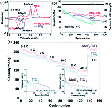 |
| | Fig. 24 (a) CV curves of the electrodes in the potential window of 1 to 3 V vs. Li+/Li at a rate of 0.1 mV s−1. (b) Cycling performance and columbic efficiencies of TiO2 and MoS2–TiO2 electrodes at a rate of 6C for 1000 cycles. (c) Rate capabilities of the MoS2–TiO2 and TiO2 samples. Reproduced with permission from ref. 173. Copyright 2015, Wiley-VCH. | |
The cycling performance of MoS2, TiO2, and the MoS2–TiO2 composite was evaluated at the current density of 6C between 1 and 3 V (Fig. 24b). MoS2–TiO2 showed better cycling stability and larger capacity than pure MoS2 and TiO2, suggesting that MoS2 can accelerate surface electrochemical reactions to increase the capacity. Moreover, rate capability tests demonstrated that MoS2–TiO2 shows improved capacity retention and rate capability compared with pure TiO2 (Fig. 24c), further indicating that MoS2 can also promote Li+ diffusion, especially at high rates. In summary, MoS2 can effectively improve the Li+ diffusion and storage capacity of MoS2–TiO2 composite through careful design at a high cut-off voltage. However, MoS2/TiO2 composites with TiO2 serving as an anode material have not been widely explored.
4.2.1.2 TiO2 as a supplemental material.
In addition, TiO2 has been widely used as a supplemental material in LIB anode materials because its excellent structural stability when associated with lithium can provide good protection of the alloy and conversion-type active materials from agglomeration and pulverization.19 In most reported MoS2/TiO2-based LIB anode materials, TiO2 mainly acts as a mechanical support against structure and volume changes of MoS2. Generally, there are two main configurations in MoS2/TiO2 composites: the first one is TiO2 coated with MoS2; the second one is MoS2 loaded on the surface of TiO2.19 The reported MoS2/TiO2-based composites for LIB applications belong to the second configuration.102,112,120,121,125–131,136,144–146,176 When they are used as LIB anode materials, MoS2 contributes most of the capacity and TiO2 protects the overall structure. For example, Mao et al.102 firstly used a TiO2 nanobelt@few-layered MoS2 (TiO2@MoS2) composite in LIBs in 2014. The electrochemical tests were carried out in the potential window of 0.01 to 3.0 V. As shown in Fig. 25a, TiO2@MoS2 exhibited the typical peaks of anatase TiO2 (eqn (8)). MoS2 can undergo a full conversion reaction with lithium after deep discharge at 0.01 V. Therefore, the cathodic peak at 0.5 V was attributed to the conversion reaction (eqn (11)). After the first discharge, MoS2 disappeared and S and Mo were generated. The subsequent electrochemical peaks of Mo and S were obviously different from those of the initial MoS2. The peak at 2.0 V in the discharge curves and the peak at 2.3 V corresponded to S (eqn (12)). The discharge/charge curves also demonstrate the reaction mechanism (Fig. 25b). The cycling tests indicated that TiO2@MoS2 exhibits significantly better cycling stability than MoS2 and obviously larger reversible capacity than TiO2 (Fig. 25c), indicating that TiO2@MoS2 has better structural stability than MoS2 and more lithium storage sites than TiO2. In other words, the TiO2@MoS2 composites simultaneously possess high structural stability and numerous lithium storage sites. Moreover, the TiO2@MoS2 composite showed good rate capability, with a reversible capacity of 417 mA h g−1 at 1000 mA g−1 (Fig. 25d). The SEM images of the TiO2@MoS2 composites before cycling and after 100 cycles directly demonstrate their structural stability (Fig. 25e and f). This electrochemical mechanism and improved LIB performance can also be found in subsequent research. Currently, increasing attention has been drawn to exploring MoS2/TiO2-based composites for application in LIBs.| | | LixMoS2 + (4 − x)Li+ + (4 − x)e− → Mo + 2Li2S | (11) |
| | | S + 2Li+ + 2e− ↔ Li2S | (12) |
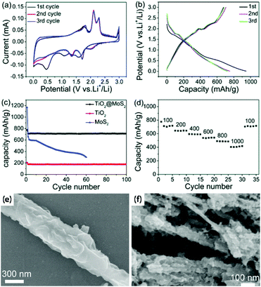 |
| | Fig. 25 (a) CV curves of TiO2@MoS2 measured in the voltage range of 0.01 to 3.0 V with a scan rate of 0.1 mV s−1, (b) discharge/charge curves for the first three cycles, (c) cycling performance of TiO2@MoS2, TiO2 and MoS2 tested in the range of 0.01 to 3.0 V vs. Li+/Li at a current density of 100 mA g−1, (d) rate performance at different current densities (mA g−1), SEM images of TiO2@MoS2 (e) before cycling and (f) after 100 cycles. Reproduced with permission from ref. 102. Copyright 2014, Royal Society of Chemistry. | |
4.2.2 Sodium-ion batteries.
LIBs have been widely used in consumer electronics, transportation, and renewable energy storage devices. However, the resources of lithium are limited and cannot meet the increasing demand. Therefore, researchers are eagerly searching for more abundant materials. Recently, sodium has been considered as a promising alternative due to its earth abundance, low cost and similar electrochemical properties.6 MoS2/TiO2 composites have also been used as anode materials in sodium-ion batteries (SIBs).100,123 The SIB performance of MoS2/TiO2-based anode materials is summarized in Table 11. For example, Liao and co-workers123 prepared TiO2-B/MoS2 nanowire arrays through a simple hydrothermal method as a SIB anode material. Fig. 26a and b display the CV and discharge–charge curves of the TiO2-B/MoS2 electrode in a wide voltage range between 0.01 V and 3.0 V. The sodium ion storage mechanism of TiO2-B/MoS2 composites is similar to the lithium ion storage mechanism. The electrochemical reactions of the TiO2-B/MoS2 electrode are composed of the reactions of TiO2 and MoS2.100,123 They involve Na+ intercalation into the TiO2 nanosheets (eqn (13)), the insertion of Na+ in MoS2 to form NaxMoS2 (eqn (14)), and the further conversion of NaxMoS2 into Mo and Na2S (eqn (15)) in the first cycle. After the first cycle, the Na+ storage reaction in TiO2 remains unchanged; however, the Na+ storage reaction of MoS2 no longer occurs. The S transformed from MoS2 can store sodium ions (eqn (16)). The cycling performance of TiO2-B and TiO2-B/MoS2 nanowire array electrodes is exhibited in Fig. 26c. Both electrodes show excellent cycling stability due to the robust TiO2 backbone. However, TiO2-B/MoS2 electrode demonstrates a much higher capacity than the TiO2-B electrode even after 100 cycles, suggesting the MoS2 material can provide numerous sodium ions storage sites. The rate capabilities of TiO2-B and TiO2-B/MoS2 in Fig. 26d show the similar phenomenon in all tested current densities. Therefore, MoS2/TiO2-based composites exhibit great potential application in SIBs, which requires more attention and deeper research.| | | TiO2 + xNa+ + xe− ↔ NaxTiO2 | (13) |
| | | MoS2 + xNa+ + xe− → NaxMoS2 | (14) |
| | | LixMoS2 + (4 − x)Na+ + (4 − x)e− → Mo + 2Na2S | (15) |
| | | S + 2Na+ + 2e− ↔ Na2S | (16) |
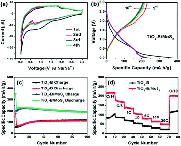 |
| | Fig. 26 (a) CV curves and (b) discharge–charge profiles of TiO2-B/MoS2 nanowire array electrodes. (c) Cycling performance and (d) rate capability of TiO2-B and TiO2-B/MoS2 nanowire array electrodes. Reproduced with permission from ref. 123. Copyright 2015, Royal Society of Chemistry. | |
Table 11 A summary of the SIBs performance of MoS2/TiO2-based anode materials
| Material |
TiO2 weight content |
Voltage range |
Capacities (mA h g−1) at current different densities (A g−1) (after 100 cycles) |
Capacities (mA h g−1) at different current densities (A g−1) |
Ref. (year) |
| TiO2-B/MoS2 nanowire arrays |
N/A |
0.01 to 3 V |
191 at 0.02 |
214, 77, 48 at 0.02, 1, 4 |
123 (2016) |
| MoS2-1 nm–TiO2 |
N/A |
0.01 to 2.5 V |
74.1% of its second cycle capacity at 0.2 (150 cycles); 182 at 0.5 (200 cycles) |
369, 754 at 0.8, 0.05 |
100 (2017) |
4.2.3 Strategies for enhancement of battery performance.
4.2.3.1 Interface engineering.
It is well known that the interfaces of composite materials play a key role in their applications. For MoS2/TiO2 composites, the interface between MoS2 and TiO2 determines the structural stability and interface electron transfer directly when used in rechargeable batteries. Generally, the reported MoS2/TiO2-based composites are synthesized by in situ strategies so the MoS2 can make strong contact with TiO2 through chemical bonds. However, MoS2/TiO2 composites are more likely to display dendritic/dumbbell-like morphologies102,120,126,127,129–131,176 due to the significant lattice mismatch between TiO2 and MoS2. Therefore, considerable amounts of MoS2 cannot directly contact the TiO2 backbone, which reduces the structural stability and electrical conductivity of the overall composites. There are two main strategies to improve the interface. First, some researchers constructed a nanoscopic/atomic intimate interface between TiO2 and MoS2 through a rationally designed hydrothermal method.121 As shown in Table 6, the core–shell TiO2@MoS2 nano-onion heterostructures show conformal coverage with a high-quality interface. Moreover, the high-quality interface between TiO2 and MoS2 also results in exciting synergistic effects of both components. As a result, when the TiO2@MoS2 nano-onions were evaluated as a LIBs anode, they displayed superior lithium ion storage performance, especially at high current densities (see Table 10). Second, we designed a “surface-to-surface” interaction between 2D TiO2 and 2D MoS2 with the assistance of glucose to improve the interface in our previous studies.128,144 As shown in Fig. 27a and b, most of the 2D MoS2 is tightly covered on the surface of TiO2 in the 3D FL-MoS2@TiO2 composite. Therefore, there is a large interface between 2D MoS2 and 2D TiO2. Both the strong interface and large contact area between MoS2 and TiO2 enable high structural stability and rapid interface electron transfer. Also, there are synergistic effects between TiO2 and MoS2. As a result, the 3D FL-MoS2@TiO2 electrode shows excellent cycling stability and rate capability which are higher than those of MoS2/TiO2 electrodes without strong interfaces (Fig. 27c and d). Therefore, “surface-to-surface” contact between MoS2 and TiO2 is also an effective strategy to improve the interface.
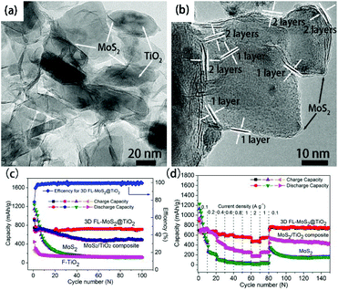 |
| | Fig. 27 TEM images of (a, b) 3D FL-MoS2@TiO2. (c) Cycling performance of F-TiO2, MoS2, the MoS2/TiO2 composite and 3D FL-MoS2@TiO2. (d) Rate-capability performance of electrodes of MoS2, MoS2/TiO2 composite and 3D FL-MoS2@TiO2. Reproduced with permission from ref. 131. Copyright 2015, Royal Society of Chemistry. | |
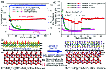 |
| | Fig. 28 (a) Cycling performance and (b) rate capability performance of pure MoS2, UT-TiO2 and UT-TiO2/C@DR-MoS2 nanocomposites. (c) Illustration of the lithiation process of UT-TiO2/C@DR-MoS2 in the first cycle. Reproduced with permission from ref. 128. Copyright 2016, Elsevier. | |
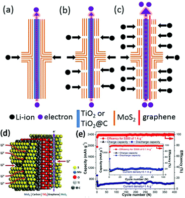 |
| | Fig. 29 Schematic of anodes with Li-ion and electron transport paths depicting the reference 2D–2D MoS2–TiO2-based anode materials with (a) defect-free basal surface of MoS2 shell, (b) many-defect MoS2 shell and (c) many-defect MoS2 shell and incorporation of graphene. (d) Illustration of the lithiation process of the optimized G/TiO2@C/MoS2 in the first cycle. (e) Cycle performance of the optimized G/TiO2@C/MoS2 at 0.1 and 1 A g−1. Reproduced with permission from ref. 145. Copyright 2017, Elsevier. | |
5. Summary and perspectives
Both TiO2 and MoS2 are interesting materials in the fields of photocatalysis and rechargeable batteries because of their low cost, unique structures, and excellent physicochemical properties. However, TiO2 and MoS2 alone have several inherent drawbacks which severely restrict their practical applications. The properties of TiO2 and MoS2 are highly complementary. Therefore, in recent years, increasing numbers of researchers have devoted much effort to constructing MoS2/TiO2 composites for enhanced photocatalytic activity and rechargeable battery performance. In this review, we have summarized the recent advances in the synthesis methods and correlated mechanisms of MoS2/TiO2-based composites, as well as their applications in photocatalytic degradation, photocatalytic hydrogen evolution, photocatalytic CO2 reduction, LIBs and SIBs, and various strategies for enhancement of their photocatalytic activities and performance in battery applications. The achieved progress demonstrates that coupling TiO2 with MoS2 in a suitable manner can effectively improve the photocatalytic activity and battery performance of pure TiO2 and MoS2. Although considerable developments have been realized in these areas, some fundamental and essential issues require more effort and further research.
Firstly, although both TiO2 and MoS2 show facile preparation, abundance, and low cost, the reported synthesis methods of MoS2/TiO2-based composites are complex, costly, and unsatisfactory. Among these, the ex situ synthesis strategy shows advantages of low cost and scalable production. However, the TiO2 and MoS2 in the obtained MoS2/TiO2-based composites exhibit heterogeneous dispersion with weak interface interaction. For the in situ strategy, the most frequently utilized methods are hydrothermal and solvothermal methods, leading to strong interface contact between MoS2 and TiO2 in the fabricated MoS2/TiO2 composites. However, the production yield ranging from milligrams to grams is quite low. Moreover, due to significant lattice mismatch between TiO2 and MoS2, the MoS2/TiO2-based composites prepared via solution methods show dendritic/dumbbell-like morphologies. Therefore, considerable amounts of MoS2 cannot directly contact TiO2, resulting in low-quality interfaces. The interface lies at the heart of the overall properties of these composites. Therefore, more attention must be paid to the controlled preparation of MoS2/TiO2-based composites with high-quality interfaces. In summary, it is highly desirable to develop a facile and inexpensive method for preparing MoS2/TiO2-based composites with high-quality interfaces. Understanding and controlling the synthesis process is believed to be the key step to achieve further breakthroughs in photocatalysis and rechargeable battery research.
Secondly, for photocatalysis applications, the photocatalytic activities of MoS2/TiO2-based photocatalysts suffer from poor visible-light harvesting, weak contact, deficient catalytic active sites, and low electrical conductivity. Therefore, much effort has been devoted to enhance their photocatalytic activities, such as visible-light harvesting expansion, interface engineering, MoS2 engineering, and graphene loading. However, the reported studies of these enhancement strategies are limited; therefore, the photocatalytic activity obtained to date is still not very satisfactory. To further improve the photocatalytic activity of MoS2/TiO2-based photocatalysts, it is necessary to systematically understand and adjust the strategies with smart design and synthesis. In addition, researchers have paid more attention to the design and synthesis of MoS2/TiO2-based composites at the nanostructure level and less attention to fundamental understanding of the transport of charge carriers across the interface and the catalytic processes associated with the active sites at the molecular and atomic levels. Therefore, it is necessary to deeply study and understand the mechanisms of generation, transport, and reaction processes of these complex charge carriers based on density functional theory (DFT) calculations, X-ray absorption near edge structure (XANES) studies, atomic level high-angle annular dark field-scanning TEM (HADDF-STEM), and in situ time-resolved spectroscopy. In particular, additional sacrificial reagents such as methanol, ethanol, lactic acid, formic acid, TEOA, and Na2S–Na2S2O3 pairs have been added to the aqueous solution as electron donors for photocatalytic hydrogen evolution. However, these additional sacrificial reagents can damage the reaction stability, affect the cycle life and reduce the solar energy conversation efficiency, which is detrimental to practical applications. Therefore, there is an urgent need to develop overall water splitting systems that use MoS2/TiO2-based composites as photocatalysts. In addition, photocatalytic CO2 reduction has gained increasing interest. However, the reported photolytic activity based on MoS2/TiO2 photocatalysts is low, and the CO2 reduction mechanism is still unclear. It is necessary to improve the efficiency of the CO2 reduction process and carefully investigate the photocatalytic CO2 reduction mechanism.
Thirdly, in the case of rechargeable batteries, the electrochemical performance is determined by the storage sites, electron transport, Li/Na ion diffusion, and structural stability of the electrode. These properties are controlled by adjusting the structure, composition, and morphology of the electrode. The ideal MoS2/TiO2-based electrode should have the intriguing traits of a high-quality interface, large amounts of few-layer, defect-rich MoS2, and loading of graphene or other materials with high electrical conductivity. Although significant advances have been achieved to enhance the performance of MoS2/TiO2-based LIBs, including high initial coulombic efficiency, large storage capacity, and high-rate long-cycle life, studies of NIBs have been rarely reported to date, probably due to the difficulty of Na-ion transport. Therefore, it is still necessary to investigate the structure, composition, and microscopic morphology of electrodes during battery operation via advanced in situ characterization techniques.
In summary, MoS2/TiO2-based composites show promising potential in the photocatalysis and rechargeable battery fields. However, this research is still in an early stage, and many challenges remain. We believe this review will aid understanding of the advances and challenges in the development of promising photocatalysts and rechargeable batteries based on MoS2/TiO2-based composites.
Conflicts of interest
There are no conflicts to declare.
Acknowledgements
The authors acknowledge financial support by the National Natural Science Foundation of China (Grant No. 51472177, 11474216, and 51272173), the State Key Program of National Natural Science of China (Grant No. 51531004) and the China-EU Science and Technology Cooperation Project (Grant No. SQ2013ZOA100006). The authors also thank Tianshuai Wang and Lichao Guo for their help with the graphical abstract.
Notes and references
- D. Ravelli, D. Dondi, M. Fagnoni and A. Albini, Chem. Soc. Rev., 2009, 38, 1999–2011 RSC.
- D. Bahnemann, Sol. Energy, 2004, 77, 445–459 CrossRef CAS.
- P. V. Kamat, J. Phys. Chem. C, 2007, 111, 2834–2860 CAS.
- B. Dunn, H. Kamath and J.-M. Tarascon, Science, 2011, 334, 928–935 CrossRef CAS PubMed.
- M. Armand and J. M. Tarascon, Nature, 2008, 451, 652–657 CrossRef CAS PubMed.
- M. D. Slater, D. Kim, E. Lee and C. S. Johnson, Adv. Funct. Mater., 2013, 23, 947–958 CrossRef CAS.
- H. Pan, Y.-S. Hu and L. Chen, Energy Environ. Sci., 2013, 6, 2338–2360 CAS.
- D.-D. Zhu, J. L. Liu and S. Z. Qiao, Adv. Mater., 2016, 28, 3423–3452 CrossRef CAS PubMed.
- Y. Tang, Z. Jiang, G. Xing, A. Li, P. D. Kanhere, Y. Zhang, T. C. Sum, S. Li, X. Chen, Z. Dong and Z. Chen, Adv. Funct. Mater., 2013, 23, 2932–2940 CrossRef CAS.
- J. Mao, M. Ge, J. Huang, Y. Lai, C. Lin, K. Zhang, K. Meng and Y. Tang, J. Mater. Chem. A, 2017, 5, 11873–11881 CAS.
- A. Fujishima and K. Honda, Nature, 1972, 238, 37–38 CrossRef CAS PubMed.
- A. Fujishima, X. Zhang and D. A. Tryk, Surf. Sci. Rep., 2008, 63, 515–582 CrossRef CAS.
- X. Chen and S. S. Mao, Chem. Rev., 2007, 107, 2891–2959 CrossRef CAS PubMed.
- R. Asahi, T. Morikawa, T. Ohwaki, K. Aoki and Y. Taga, Science, 2001, 293, 269–271 CrossRef CAS PubMed.
- K. Nakata and A. Fujishima, J. Photochem. Photobiol., C, 2012, 13, 169–189 CrossRef CAS.
- Z. Jiang, Y. Tang, Q. Tay, Y. Zhang, O. I. Malyi, D. Wang, J. Deng, Y. Lai, H. Zhou, X. Chen, Z. Dong and Z. Chen, Adv. Energy Mater., 2013, 3, 1368–1380 CrossRef CAS.
- G.-N. Zhu, Y.-G. Wang and Y.-Y. Xia, Energy Environ. Sci., 2012, 5, 6652–6667 CAS.
- Z. Yang, D. Choi, S. Kerisit, K. M. Rosso, D. Wang, J. Zhang, G. Graff and J. Liu, J. Power Sources, 2009, 192, 588–598 CrossRef CAS.
- T. Song and U. Paik, J. Mater. Chem. A, 2016, 4, 14–31 CAS.
- Y. Mei, Y. Huang and X. Hu, J. Mater. Chem. A, 2016, 4, 12001–12013 CAS.
- J. Tian, Z. Zhao, A. Kumar, R. I. Boughton and H. Liu, Chem. Soc. Rev., 2014, 43, 6920–6937 RSC.
- Y. Tang, Y. Zhang, J. Deng, J. Wei, L. H. Tam, B. K. Chandran, Z. Dong, Z. Chen and X. Chen, Adv. Mater., 2014, 26, 6111–61118 CrossRef CAS PubMed.
- Y. Tang, Y. Zhang, J. Deng, D. Qi, W. R. Leow, J. Wei, S. Yin, Z. Dong, R. Yazami, Z. Chen and X. Chen, Angew. Chem., Int. Ed., 2014, 53, 13488–13492 CrossRef CAS PubMed.
- Y. Tang, Y. Zhang, W. Li, B. Ma and X. Chen, Chem. Soc. Rev., 2015, 44, 5926–5940 RSC.
- N. Wu, J. Wang, D. N. Tafen, H. Wang, J.-G. Zheng, J. P. Lewis, X. Liu, S. S. Leonard and A. Manivannan, J. Am. Chem. Soc., 2010, 132, 6679–6685 CrossRef CAS PubMed.
- L. Ren, Y. Li, J. Hou, J. Bai, M. Mao, M. Zeng, X. Zhao and N. Li, Appl. Catal., B, 2016, 181, 625–634 CrossRef CAS.
- H. Dong, G. Zeng, L. Tang, C. Fan, C. Zhang, X. He and Y. He, Water Res., 2015, 79, 128–146 CrossRef CAS PubMed.
- H. Xu, S. Ouyang, L. Liu, P. Reunchan, N. Umezawa and J. Ye, J. Mater. Chem. A, 2014, 2, 12642–12661 CAS.
- H. Xu, P. Reunchan, S. Ouyang, H. Tong, N. Umezawa, T. Kako and J. Ye, Chem. Mater., 2013, 25, 405–411 CrossRef CAS.
- L. Pan, S. Wang, J. Xie, L. Wang, X. Zhang and J.-J. Zou, Nano Energy, 2016, 28, 296–303 CrossRef CAS.
- J. Long, H. Chang, Q. Gu, J. Xu, L. Fan, S. Wang, Y. Zhou, W. Wei, L. Huang, X. Wang, P. Liu and W. Huang, Energy Environ. Sci., 2014, 7, 973–977 CAS.
- T. Tachikawa, M. Minohara, Y. Hikita, C. Bell and H. Y. Hwang, Adv. Mater., 2015, 27, 7458–7461 CrossRef CAS PubMed.
- J. Jin, C. Wang, X.-N. Ren, S.-Z. Huang, M. Wu, L.-H. Chen, T. Hasan, B.-J. Wang, Y. Li and B.-L. Su, Nano Energy, 2017, 38, 118–126 CrossRef CAS.
- B. Han and Y. H. Hu, Energy Sci. Eng., 2016, 4, 285–304 CrossRef CAS.
- Y.-J. Yuan, H.-W. Lu, Z.-T. Yu and Z.-G. Zou, ChemSusChem, 2015, 8, 4113–4127 CrossRef CAS PubMed.
- X. Zou and Y. Zhang, Chem. Soc. Rev., 2015, 44, 5148–5180 RSC.
- Y. Li, Y.-L. Li, B. Sa and R. Ahuja, Catal. Sci. Technol., 2017, 7, 545–559 CAS.
- A. B. Laursen, S. Kegnaes, S. Dahl and I. Chorkendorff, Energy Environ. Sci., 2012, 5, 5577–5591 CAS.
- S. Chen, J. Duan, Y. Tang, B. Jin and S. Z. Qiao, Nano Energy, 2015, 11, 11–18 CrossRef CAS.
- J. Ran, G. Gao, F. T. Li, T. Y. Ma, A. Du and S. Z. Qiao, Nat. Commun., 2017, 8, 13907 CrossRef CAS PubMed.
- H. S. Lee, S.-W. Min, Y.-G. Chang, M. K. Park, T. Nam, H. Kim, J. H. Kim, S. Ryu and S. Im, Nano Lett., 2012, 12, 3695–3700 CrossRef CAS PubMed.
- K. F. Mak, C. Lee, J. Hone, J. Shan and T. F. Heinz, Phys. Rev. Lett., 2010, 105, 136805 CrossRef PubMed.
- E. S. Kadantsev and P. Hawrylak, Solid State Commun., 2012, 152, 909–913 CrossRef CAS.
- Y. Tang, Y. Zhang, X. Rui, D. Qi, Y. Luo, W. R. Leow, S. Chen, J. Guo, J. Wei, W. Li, J. Deng, Y. Lai, B. Ma and X. Chen, Adv. Mater., 2016, 28, 1567–1576 CrossRef CAS PubMed.
- Y. Zhang, O. I. Malyi, Y. Tang, J. Wei, Z. Zhu, H. Xia, W. Li, J. Guo, X. Zhou, Z. Chen, C. Persson and X. Chen, Angew. Chem., Int. Ed., 2017, 56, 14847–14852 CrossRef CAS PubMed.
- Y. Tang, J. Deng, W. Li, O. I. Malyi, Y. Zhang, X. Zhou, S. Pan, J. Wei, Y. Cai, Z. Chen and X. Chen, Adv. Mater., 2017, 29, 1701828 CrossRef PubMed.
- Y. Zhang, X. Rui, Y. Tang, Y. Liu, J. Wei, S. Chen, W. R. Leow, W. Li, Y. Liu, J. Deng, B. Ma, Q. Yan and X. Chen, Adv. Energy Mater., 2016, 6, 1502409 CrossRef.
- T. Stephenson, Z. Li, B. Olsen and D. Mitlin, Energy Environ. Sci., 2014, 7, 209–231 CAS.
- T. Wang, S. Chen, H. Pang, H. Xue and Y. Yu, Adv. Sci., 2016, 4, 1600289 CrossRef PubMed.
- X. Zhang, Z. Lai, C. Tan and H. Zhang, Angew. Chem., Int. Ed., 2016, 55, 8816–8838 CrossRef CAS PubMed.
- Y. Xiao, S. H. Lee and Y.-K. Sun, Adv. Energy Mater., 2017, 7, 1601329 CrossRef.
- H. Li, Y. Shi, M.-H. Chiu and L.-J. Li, Nano Energy, 2015, 18, 293–305 CrossRef CAS.
- X. Xu, W. Liu, Y. Kim and J. Cho, Nano Today, 2014, 9, 604–630 CrossRef CAS.
- S. Wu, Y. Du and S. Sun, Chem. Eng. J., 2017, 307, 189–207 CrossRef CAS.
- Y. Zhang, Z. Jiang, J. Huang, L. Y. Lim, W. Li, J. Deng, D. Gong, Y. Tang, Y. Lai and Z. Chen, RSC Adv., 2015, 5, 79479–79510 RSC.
- M. Ge, C. Cao, J. Huang, S. Li, Z. Chen, K.-Q. Zhang, S. S. Al-Deyab and Y. Lai, J. Mater. Chem. A, 2016, 4, 6772–6801 CAS.
- D. T. Cromer and K. Herrington, J. Am. Chem. Soc., 1955, 77, 4708–4709 CrossRef CAS.
- A. Di Paola, M. Bellardita and L. Palmisano, Catalysts, 2013, 3, 36 CrossRef CAS.
- A. R. Armstrong, G. Armstrong, J. Canales and P. G. Bruce, Angew. Chem., Int.
Ed., 2004, 43, 2286–2288 CrossRef CAS PubMed.
- W. Wunderlich, T. Oekermann, L. Miao, N. T. Hue, S. Tanemura and M. Tanemura, J. Ceram. Process. Res., 2004, 5(4), 343–354 Search PubMed.
- A. T. Paxton and L. Thiên-Nga, Phys. Rev. B: Condens. Matter, 1998, 57, 1579–1584 CrossRef CAS.
- Q. Shen, K. Katayama, T. Sawada, M. Yamaguchi, Y. Kumagai and T. Toyoda, Chem. Phys. Lett., 2006, 419, 464–468 CrossRef CAS.
- Q. H. Wang, K. Kalantar-Zadeh, A. Kis, J. N. Coleman and M. S. Strano, Nat. Nanotechnol., 2012, 7, 699–712 CrossRef CAS PubMed.
- I. Song, C. Park and H. C. Choi, RSC Adv., 2015, 5, 7495–7514 RSC.
- F. Wypych and R. Schollhorn, J. Chem. Soc., Chem. Commun., 1992, 1386–1388 RSC.
- R. G. Dickinson and L. Pauling, J. Am. Chem. Soc., 1923, 45, 1466–1471 CrossRef CAS.
- F. Jellinek, G. Brauer and H. Muller, Nature, 1960, 185, 376–377 CrossRef CAS.
- F. E. Wickman and D. K. Smith, Am. Mineral., 1967, 55, 1843–1856 Search PubMed.
- K. F. Mak, C. Lee, J. Hone, J. Shan and T. F. Heinz, Phys. Rev. Lett., 2010, 105, 136805 CrossRef PubMed.
- A. Wilson and A. D. Yoffe, Adv. Phys., 1969, 18, 193–335 CrossRef.
- G. Eda, H. Yamaguchi, D. Voiry, T. Fujita, M. Chen and M. Chhowalla, Nano Lett., 2011, 11, 5111–5116 CrossRef CAS PubMed.
- D. Voiry, M. Salehi, R. Silva, T. Fujita, M. Chen, T. Asefa, V. B. Shenoy, G. Eda and M. Chhowalla, Nano Lett., 2013, 13, 6222–6227 CrossRef CAS PubMed.
- R. Kappera, D. Voiry, S. E. Yalcin, B. Branch, G. Gupta, A. D. Mohite and M. Chhowalla, Nat. Mater., 2014, 13, 1128–1134 CrossRef CAS PubMed.
- Y. Pi, Z. Li, D. Xu, J. Liu, Y. Li, F. Zhang, G. Zhang, W. Peng and X. Fan, ACS Sustainable Chem. Eng., 2017, 5, 5175–5182 CrossRef CAS.
- S. Bai, L. Wang, X. Chen, J. Du and Y. Xiong, Nano Res., 2015, 8, 175–183 CrossRef CAS.
- L. Karimi, Pol. J. Chem. Technol., 2017, 19, 56–60 CAS.
- D. Wang, Y. Xu, F. Sun, Q. Zhang, P. Wang and X. Wang, Appl. Surf. Sci., 2016, 377, 221–227 CrossRef CAS.
- P. Zhang, T. Tachikawa, M. Fujitsuka and T. Majima, Chem. Commun., 2015, 51, 7187–7190 RSC.
- S. Cravanzola, L. Muscuso, F. Cesano, G. Agostini, A. Damin, D. Scarano and A. Zecchina, Langmuir, 2015, 31, 5469–5478 CrossRef CAS PubMed.
- B. Pourabbas and B. Jamshidi, Chem. Eng. J., 2008, 138, 55–62 CrossRef CAS.
- W.-K. Jo, T. Adinaveen, J. J. Vijaya and N. C. Sagaya Selvam, RSC Adv., 2016, 6, 10487–10497 RSC.
- X. Liu, Z. Xing, H. Zhang, W. Wang, Y. Zhang, Z. Li, X. Wu, X. Yu and W. Zhou, ChemSusChem, 2016, 9, 1118–1124 CrossRef CAS PubMed.
- Y. Zhu, Q. Ling, Y. Liu, H. Wang and Y. Zhu, Phys. Chem. Chem. Phys., 2015, 17, 933–940 RSC.
- Y. Yu, J. Wan, Z. Yang and Z. Hu, J. Colloid Interface Sci., 2017, 502, 100–111 CrossRef CAS PubMed.
- W. Han, C. Zang, Z. Huang, H. Zhang, L. Ren, X. Qi and J. Zhong, Int. J. Hydrogen Energy, 2014, 39, 19502–19512 CrossRef CAS.
- D. B. Nimbalkar, H.-H. Lo, P. V. R. K. Ramacharyulu and S.-C. Ke, RSC Adv., 2016, 6, 31661–31667 RSC.
- I. Tacchini, E. Terrado, A. Anso and M. T. Marti, Micro Nano Lett. IET, 2011, 6, 932–936 CrossRef CAS.
- Q. Liu, Z. Pu, A. Asiri, A. Qusti, A. Al-Youbi and X. Sun, J. Nanopart. Res., 2013, 15, 2057 CrossRef.
- X. Zhu, C. Yang, F. Xiao, J. Wang and X. Su, New J. Chem., 2015, 39, 683–688 RSC.
- M. M. Ali and K. N. Y. Sandhya, New J. Chem., 2016, 40, 8123–8130 RSC.
- L. Wang, C. Wang, W. Liu, Q. Chen and M. He, Tetrahedron Lett., 2016, 57, 1771–1774 CrossRef CAS.
- M. Sabarinathan, S. Harish, J. Archana, M. Navaneethan, H. Ikeda and Y. Hayakawa, RSC Adv., 2017, 7, 24754–24763 RSC.
- M. Sun, Y. Wang, Y. Fang, S. Sun and Z. Yu, J. Alloys Compd., 2016, 684, 335–341 CrossRef CAS.
- W. Zhang, X. Xiao, L. Zheng and C. Wan, Appl. Surf. Sci., 2015, 358, 468–478 CrossRef CAS.
- W. Zhang, X. Xiao, L. Zheng and C. Wan, Can. J. Chem. Eng., 2015, 93, 1594–1602 CrossRef CAS.
- R. Xiaohui, Q. Xiang, S. Yongzhen, X. Si, X. Guanghua, Z. Zhen, H. Zongyu and Z. Jianxin, J. Phys. D: Appl. Phys., 2016, 49, 315304 CrossRef.
- Q. Xiang, J. Yu and M. Jaroniec, J. Am. Chem. Soc., 2012, 134, 6575–6578 CrossRef CAS PubMed.
- W. Zhang, X. Xiao, Y. Li, X. Zeng, L. Zheng and C. Wan, Appl. Surf. Sci., 2016, 389, 496–506 CrossRef CAS.
- X. Yang, H. Huang, M. Kubota, Z. He, N. Kobayashi, X. Zhou, B. Jin and J. Luo, Mater. Res. Bull., 2016, 76, 79–84 CrossRef CAS.
- W. Ren, W. Zhou, H. Zhang and C. Cheng, ACS Appl. Mater. Interfaces, 2017, 9, 487–495 CAS.
- W. Zhou, Z. Yin, Y. Du, X. Huang, Z. Zeng, Z. Fan, H. Liu, J. Wang and H. Zhang, Small, 2013, 9, 140–147 CrossRef CAS PubMed.
- M. Mao, L. Mei, D. Guo, L. Wu, D. Zhang, Q. Li and T. Wang, Nanoscale, 2014, 6, 12350–12353 RSC.
- C. Liu, L. Wang, Y. Tang, S. Luo, Y. Liu, S. Zhang, Y. Zeng and Y. Xu, Appl. Catal., B, 2015, 164, 1–9 CrossRef CAS.
- H. Liu, T. Lv, C. Zhu, X. Su and Z. Zhu, J. Mol. Catal. A: Chem., 2015, 396, 136–142 CrossRef CAS.
- X. Zhang, C. Shao, X. Li, F. Miao, K. Wang, N. Lu and Y. Liu, J. Alloys Compd., 2016, 686, 137–144 CrossRef CAS.
- H. Li, Y. Wang, G. Chen, Y. Sang, H. Jiang, J. He, X. Li and H. Liu, Nanoscale, 2016, 8, 6101–6109 RSC.
- L. Zheng, S. Han, H. Liu, P. Yu and X. Fang, Small, 2016, 12, 1527–1536 CrossRef CAS PubMed.
- B. Ma, P.-Y. Guan, Q.-Y. Li, M. Zhang and S.-Q. Zang, ACS Appl. Mater. Interfaces, 2016, 8, 26794–26800 CAS.
- J. Wang, B. Wei, L. Xu, H. Gao and W. Sun, J. Chem. Mater. Lett., 2016, 179, 42–46 CrossRef CAS.
- X. Li, X. Li, J. Cheng, D. Yuan, W. Ni, Q. Guan, L. Gao and B. Wang, Nano Energy, 2016, 21, 228–237 CrossRef CAS.
- X. Liu, X. Huo, P. Liu, Y. Tang, J. Xu, X. Liu and Y. Zhou, Electrochim. Acta, 2017, 242, 327–336 CrossRef CAS.
- Y. Zhang, S. Zhao, X. Zeng, J. Xiao, P. Dong, J. Zhao, S. Sun, L. Huang and X. Li, J. Mater. Sci.: Mater. Electron., 2017, 28, 9519–9527 CrossRef CAS.
- C. Liu, J. Chen, H. Che, K. Huang, P. A. Charpentier, W. Z. Xu, W. Shi and H. Dong, RSC Adv., 2017, 7, 8429–8442 RSC.
- X. Liu, Z. Xing, Y. Zhang, Z. Li, X. Wu, S. Tan, X. Yu, Q. Zhu and W. Zhou, Appl. Catal., B, 2017, 201, 119–127 CrossRef CAS.
- L. Yang, X. Zheng, M. Liu, S. Luo, Y. Luo and G. Li, J. Hazard. Mater., 2017, 329, 230–240 CrossRef CAS PubMed.
- R. Tang, R. Yin, S. Zhou, T. Ge, Z. Yuan, L. Zhang and L. Yin, J. Mater. Chem. A, 2017, 5, 4962–4971 CAS.
- N. Shao, J. Wang, D. Wang and P. Corvini, Appl. Catal., B, 2017, 203, 964–978 CrossRef CAS.
- L. Wang, X. Liu, J. Luo, X. Duan, J. Crittenden, C. Liu, S. Zhang, Y. Pei, Y. Zeng and X. Duan, Angew. Chem., Int. Ed., 2017, 56, 7610–7614 CrossRef CAS PubMed.
- Y. Yuan, H. Lu, Z. Ji, J. Zhong, M. Ding, D. Chen, Y. Li, W. Tu, D. Cao, Z. Yu and Z. Zou, Chem. Eng. J., 2015, 275, 8–16 CrossRef CAS.
- S. Wang, B. Y. Guan, L. Yu and X. W. Lou, Adv. Mater., 2017, 29, 1702724 CrossRef PubMed.
- R. Dai, A. Zhang, Z. Pan, A. M. Al-Enizi, A. A. Elzatahry, L. Hu and G. Zheng, Small, 2016, 12, 2792–2799 CrossRef CAS PubMed.
- M. Shen, Z. Yan, L. Yang, P. Du, J. Zhang and B. Xiang, Chem. Commun., 2014, 50, 15447–15449 RSC.
- J.-Y. Liao, B. D. Luna and A. Manthiram, J. Mater. Chem. A, 2016, 4, 801–806 CAS.
- A. Hamdi, L. Boussekey, P. Roussel, A. Addad, H. Ezzaouia, R. Boukherroub and Y. Coffinier, Mater. Des., 2016, 109, 634–643 CrossRef CAS.
- B. Guo, K. Yu, H. Fu, Q. Hua, R. Qi, H. Li, H. Song, S. Guo and Z. Zhu, J. Mater. Chem. A, 2015, 3, 6392–6401 CAS.
- X. Li, W. Li, M. Li, P. Cui, D. Chen, T. Gengenbach, L. Chu, H. Liu and G. Song, J. Mater. Chem. A, 2015, 3, 2762–2769 CAS.
- X. Xu, Z. Fan, S. Ding, D. Yu and Y. Du, Nanoscale, 2014, 6, 5245–5250 RSC.
- B. Chen, E. Liu, F. He, C. Shi, C. He, J. Li and N. Zhao, Nano Energy, 2016, 26, 541–549 CrossRef CAS.
- G. Li, L. Yu, H. Hu, Q. Zhu, Y. Wang and Y. Yu, Electrochim. Acta, 2016, 212, 59–67 CrossRef CAS.
- W. Xu, T. Wang, Y. Yu and S. Wang, J. Alloys Compd., 2016, 689, 460–467 CrossRef CAS.
- Y. Zhou, Y. Liu, W. Zhao, F. Xie, R. Xu, B. Li, X. Zhou and H. Shen, J. Mater. Chem. A, 2016, 4, 5932–5941 CAS.
- W. Gao, M. Wang, C. Ran and L. Li, Chem. Commun., 2015, 51, 1709–1712 RSC.
- P. X. Zhao, Y. Tang, J. Mao, Y. X. Chen, H. Song, J. W. Wang, Y. Song, Y. Q. Liang and X. M. Zhang, J. Alloys Compd., 2016, 674, 252–258 CrossRef CAS.
- C. Wang, H. Lin, Z. Liu, J. Wu, Z. Xu and C. Zhang, Part. Part. Syst. Charact., 2016, 33, 221–227 CrossRef CAS.
- J. Liu, Y. Li, J. Ke, Z. Wang and H. Xiao, Catalysts, 2017, 7, 30 CrossRef.
- Q. Pang, Y. Zhao, X. Bian, Y. Ju, X. Wang, Y. Wei, B. Liu, F. Du, C. Wang and G. Chen, J. Mater. Chem. A, 2017, 5, 3667–3674 CAS.
- L. Cao, R. Wang, D. Wang, X. Li and H. Jia, Mater. Lett., 2015, 160, 286–290 CrossRef CAS.
- Y.-J. Yuan, Z.-J. Ye, H.-W. Lu, B. Hu, Y.-H. Li, D.-Q. Chen, J.-S. Zhong, Z.-T. Yu and Z.-G. Zou, ACS Catal., 2016, 6, 532–541 CrossRef CAS.
- J. Zhang, L. Huang, Z. Lu, Z. Jin, X. Wang, G. Xu, E. Zhang, H. Wang, Z. Kong, J. Xi and Z. Ji, J. Alloys Compd., 2016, 688, 840–848 CrossRef CAS.
- X. Yang, H. Huang, B. Jin, J. Luo and X. Zhou, RSC Adv., 2016, 6, 107075–107080 RSC.
- W. Tu, Y. Li, L. Kuai, Y. Zhou, Q. Xu, H. Li, X. Wang, M. Xiao and Z. Zou, Nanoscale, 2017, 9, 9065–9070 RSC.
- J. Zhang, L. Zhang, W. Yu, F. Jiang, E. Zhang, H. Wang, Z. Kong, J. Xi and Z. Ji, J. Am. Ceram. Soc., 2017, 100, 5274–5285 CrossRef CAS.
- C. Li, S. Zhang, Y. Zhou and J. Li, J. Mater. Sci.: Mater. Electron., 2017, 28, 9003–9010 CrossRef CAS.
- B. Chen, N. Zhao, L. Guo, F. He, C. Shi, C. He, J. Li and E. Liu, Nanoscale, 2015, 7, 12895–12905 RSC.
- B. Chen, E. Liu, T. Cao, F. He, C. Shi, C. He, L. Ma, Q. Li, J. Li and N. Zhao, Nano Energy, 2017, 33, 247–256 CrossRef CAS.
- B. Chen, N. Zhao, C. Wei, J. Zhou, F. He, C. Shi, C. He and E. Liu, Appl. Surf. Sci., 2017, 401, 232–240 CrossRef CAS.
- H. N. T. Phung, V. N. K. Tran, L. T. Nguyen, L. K. T. Phan, P. A. Duong and H. V. T. Le, J. Nanomater., 2017, 2017, 3197540 Search PubMed.
- W. Ho, J. C. Yu, J. Lin, J. Yu and P. Li, Langmuir, 2004, 20, 5865–5869 CrossRef CAS PubMed.
- N. Qin, J. Xiong, R. Liang, Y. Liu, S. Zhang, Y. Li, Z. Li and L. Wu, Appl. Catal., B, 2017, 202, 374–380 CrossRef CAS.
- W. Shi, S. Song and H. Zhang, Chem. Soc. Rev., 2013, 42, 5714–5743 RSC.
- H. G. Yang, C. H. Sun, S. Z. Qiao, J. Zou, G. Liu, S. C. Smith, H. M. Cheng and G. Q. Lu, Nature, 2008, 453, 638–641 CrossRef CAS PubMed.
- W.-J. Ong, L.-L. Tan, S.-P. Chai, S.-T. Yong and A. R. Mohamed, Nanoscale, 2014, 6, 1946–2008 RSC.
- B. Chen, J. Sha, W. Li, F. He, E. Liu, C. Shi, C. He, J. Li and N. Zhao, ACS Appl. Mater. Interfaces, 2016, 8, 2495–2504 CAS.
- E. Liu, J. Wang, C. Shi, N. Zhao, C. He, J. Li and J.-Z. Jiang, ACS Appl. Mater. Interfaces, 2014, 6, 18147–18151 CAS.
- H. Liu, X. Wang, C. Pan and K. M. Liew, J. Phys. Chem. C, 2012, 116, 8044–8053 CAS.
- T. Xia, W. Zhang, Z. Wang, Y. Zhang, X. Song, J. Murowchick, V. Battaglia, G. Liu and X. Chen, Nano Energy, 2014, 6, 109–118 CrossRef CAS.
- Y. Liu, A. A. Elzatahry, W. Luo, K. Lan, P. Zhang, J. Fan, Y. Wei, C. Wang, Y. Deng, G. Zheng, F. Zhang, Y. Tang, L. Mai and D. Zhao, Nano Energy, 2016, 25, 80–90 CrossRef CAS.
- Y. Li, C. Chen, M. Wang, W. Li, Y. Wang, L. Jiao and H. Yuan, J. Power Sources, 2017, 361, 326–333 CrossRef CAS.
- X.-Y. Yu, H. Hu, Y. Wang, H. Chen and X. W. Lou, Angew. Chem., Int. Ed., 2015, 54, 7395–7398 CrossRef CAS PubMed.
- Y. Li, Y. Liang, F. C. Robles Hernandez, H. Deog Yoo, Q. An and Y. Yao, Nano Energy, 2015, 15, 453–461 CrossRef CAS.
- L. Yang, W. Zhou, J. Lu, D. Hou, Y. Ke, G. Li, Z. Tang, X. Kang and S. Chen, Nano Energy, 2016, 22, 490–498 CrossRef CAS.
- S. Ding, J. S. Chen and X. W. Lou, Chem. – Eur. J., 2011, 17, 13142–13145 CrossRef CAS PubMed.
- Y. Li, L. Wang, T. Cai, S. Zhang, Y. Liu, Y. Song, X. Dong and L. Hu, Chem. Eng. J., 2017, 321, 366–374 CrossRef CAS.
- K. Chang and W. Chen, J. Mater. Chem., 2011, 21, 17175–17184 RSC.
- Z. Wang, T. Chen, W. Chen, K. Chang, L. Ma, G. Huang, D. Chen and J. Y. Lee, J. Mater. Chem. A, 2013, 1, 2202–2210 CAS.
- G. Huang, T. Chen, W. Chen, Z. Wang, K. Chang, L. Ma, F. Huang, D. Chen and J. Y. Lee, Small, 2013, 9, 3693–3703 CrossRef CAS PubMed.
- L. Yang, X. Wang, Y. Liu, Z. Yu, R. Li and J. Qiu, Catal. Sci. Technol., 2017, 7, 693–702 CAS.
- X. H. Yang, Z. Li, C. Sun, H. G. Yang and C. Li, Chem. Mater., 2011, 23, 3486–3494 CrossRef CAS.
- H. G. Yang and H. C. Zeng, J. Phys. Chem. B, 2003, 107, 12244–12255 CrossRef CAS.
- K. Chang and W. Chen, Chem. Commun., 2011, 47, 4252–4254 RSC.
- T. Ben Nasr, N. Kamoun, M. Kanzari and R. Bennaceur, Thin Solid Films, 2006, 500, 4–8 CrossRef CAS.
- X.-Q. Bao, D. Y. Petrovykh, P. Alpuim, D. G. Stroppa, N. Guldris, H. Fonseca, M. Costa, J. Gaspar, C. Jin and L. Liu, Nano Energy, 2015, 16, 130–142 CrossRef CAS.
- W. Zhuang, L. Li, J. Zhu, R. An, L. Lu, X. Lu, X. Wu and H. Ying, ChemElectroChem, 2015, 2, 374–381 CrossRef CAS.
- X. Zhou, M. Licklederer and P. Schmuki, Electrochem. Commun., 2016, 73, 33–37 CrossRef CAS.
- H. He, J. Lin, W. Fu, X. Wang, H. Wang, Q. Zeng, Q. Gu, Y. Li, C. Yan, B. K. Tay, C. Xue, X. Hu, S. T. Pantelides, W. Zhou and Z. Liu, Adv. Energy Mater., 2016, 6, 1600464 CrossRef.
- X. Zhu, X. Liang, X. Fan and X. Su, RSC Adv., 2017, 7, 38119–38124 RSC.
- K. H. Hu, X. G. Hu, Y. F. Xu and J. D. Sun, J. Mater. Sci., 2010, 45, 2640–2648 CrossRef CAS.
- E. Girel, E. Puzenat, C. Geantet and P. Afanasiev, Catal. Today, 2014, 292, 154–163 CrossRef.
- D. Kong, H. Wang, J. J. Cha, M. Pasta, K. J. Koski, J. Yao and Y. Cui, Nano Lett., 2013, 13, 1341–1347 CrossRef CAS PubMed.
- S. Kanda, T. Akita, M. Fujishima and H. Tada, J. Colloid Interface Sci., 2011, 354, 607–610 CrossRef CAS PubMed.
- W. Tu, Y. Zhou and Z. Zou, Adv. Mater., 2014, 26, 4607–4626 CrossRef CAS PubMed.
- T. F. Jaramillo, K. P. Jørgensen, J. Bonde, J. H. Nielsen, S. Horch and I. Chorkendorff, Science, 2007, 317, 100–102 CrossRef CAS PubMed.
- Y. Sun, S. Gao, F. Lei and Y. Xie, Chem. Soc. Rev., 2015, 44, 623–636 RSC.
- H. Lin, Y. Li, H. Li and X. Wang, Nano Res., 2017, 10, 1377–1392 CrossRef CAS.
- S. Zhang, H. Yang, H. Gao, R. Cao, J. Huang and X. Xu, ACS Appl. Mater. Interfaces, 2017, 9, 23635–23646 CAS.
- H. Wang, D. Kong, P. Johanes, J. J. Cha, G. Zheng, K. Yan, N. Liu and Y. Cui, Nano Lett., 2013, 13, 3426–3433 CrossRef CAS PubMed.
- Y. Lv, B. Chen, N. Zhao, C. Shi, C. He, J. Li and E. Liu, Surf. Sci., 2016, 651, 10–15 CrossRef CAS.
- E. Liu, J. Wang, C. Shi, N. Zhao, C. He, J. Li and J.-Z. Jiang, ACS Appl. Mater. Interfaces, 2014, 6, 18147–18151 CAS.
- B. Chen, Y. Meng, E. Liu, F. He, C. Shi, C. He, L. Ma and J. N. Q. Zhao, Nano Energy, 2017, 41, 154–163 CrossRef CAS.
- H. Liu, D. Su, R. Zhou, B. Sun, G. Wang and S. Z. Qiao, Adv. Energy Mater., 2012, 2, 970–975 CrossRef CAS.
- F. Xie, L. Zhang, D. Su, M. Jaroniec and S. Z. Qiao, Adv. Mater., 2017, 29, 1700989 CrossRef PubMed.
Footnote |
| † Electronic supplementary information (ESI) available. See DOI: 10.1039/c7nr07366f |
|
| This journal is © The Royal Society of Chemistry 2018 |
Click here to see how this site uses Cookies. View our privacy policy here.  a,
Yuhuan
Meng
b,
Junwei
Sha
a,
Cheng
Zhong
a,
Yuhuan
Meng
b,
Junwei
Sha
a,
Cheng
Zhong
 ac,
Wenbin
Hu
ac and
Naiqin
Zhao
 *adc
*adc


![[3 with combining macron]](https://www.rsc.org/images/entities/char_0033_0304.gif) m1
m1


![[thin space (1/6-em)]](https://www.rsc.org/images/entities/char_2009.gif) 79 and 2H-MoS2
79 and 2H-MoS2![[thin space (1/6-em)]](https://www.rsc.org/images/entities/char_2009.gif) 64 are the most stable and common crystal phases under hydrothermal synthesis conditions. For anatase TiO2, the natural and artificial crystal exposes the most stable (101) plane (rectangular cell: 5.48 Å × 3.78 Å).121 Meanwhile, anatase TiO2 nanosheets with exposed (001) planes (hexagonal cell: 3.79 Å × 3.79 Å) have gained considerable attention and great research interest due to their novel properties.151–155 2H-MoS2, which is a typical layered structure material, shows a dominant (002) surface (hexagonal cell: 2.41 Å × 2.41 Å).121 The unit structures are shown in Fig. 7. The lattice of the 2H-MoS2 (002) plane is elongated by 36.2% and 5.6% to match the anatase (101) plane and (001) plane, respectively. The large lattice mismatch between MoS2 and TiO2, especially common anatase TiO2 with exposed (101) planes, impedes the epitaxial nucleation and growth of MoS2 nanosheets on the TiO2 substrate/template. Meanwhile, the TiO2 substrate is always negatively charged, and the commonly used Mo sources are Mo-containing anions such as MoO42− and MoS42−; thus, the charge incompatibility between negatively charged TiO2 and Mo-containing anions causes them to repel each other. As a result, the formed MoS2 nanosheets tend to assemble into microspheres instead of coating the TiO2 surface (Fig. 8). To address this issue, many studies have explored the abovementioned two aspects: TiO2 surface states and reaction parameters.
64 are the most stable and common crystal phases under hydrothermal synthesis conditions. For anatase TiO2, the natural and artificial crystal exposes the most stable (101) plane (rectangular cell: 5.48 Å × 3.78 Å).121 Meanwhile, anatase TiO2 nanosheets with exposed (001) planes (hexagonal cell: 3.79 Å × 3.79 Å) have gained considerable attention and great research interest due to their novel properties.151–155 2H-MoS2, which is a typical layered structure material, shows a dominant (002) surface (hexagonal cell: 2.41 Å × 2.41 Å).121 The unit structures are shown in Fig. 7. The lattice of the 2H-MoS2 (002) plane is elongated by 36.2% and 5.6% to match the anatase (101) plane and (001) plane, respectively. The large lattice mismatch between MoS2 and TiO2, especially common anatase TiO2 with exposed (101) planes, impedes the epitaxial nucleation and growth of MoS2 nanosheets on the TiO2 substrate/template. Meanwhile, the TiO2 substrate is always negatively charged, and the commonly used Mo sources are Mo-containing anions such as MoO42− and MoS42−; thus, the charge incompatibility between negatively charged TiO2 and Mo-containing anions causes them to repel each other. As a result, the formed MoS2 nanosheets tend to assemble into microspheres instead of coating the TiO2 surface (Fig. 8). To address this issue, many studies have explored the abovementioned two aspects: TiO2 surface states and reaction parameters.


![[thin space (1/6-em)]](https://www.rsc.org/images/entities/char_2009.gif) 156–158 and support MoS2
156–158 and support MoS2![[thin space (1/6-em)]](https://www.rsc.org/images/entities/char_2009.gif) 159–161 with strong chemical bonds. Therefore, amorphous carbon can be used as an ideal intermediate layer material in this process. Recently, as shown in Fig. 9a, Wang and co-workers120 reported the synthesis of hierarchical tubular structures by sequential coating of a nitrogen-doped carbon (NC) layer and MoS2 nanosheets on TiO2 nanotubes (designated as TiO2@NC@MoS2). According to Fig. 9b and c, we can observe that the NC layer tightly coats the TiO2 surface in TiO2@NC. The prefabricated TiO2@NC is then used to grow MoS2 nanosheets. After the hydrothermal and calcination processes, as shown in Fig. 9d and e, the NC intermediate layer acts as a bonding interface to maintain good contact between the TiO2 nanotubes and MoS2 nanosheets in the obtained TiO2@NC@MoS2; this is a very stable architecture. The NC intermediate layer can also increase electrical conductivity, which is beneficial to rechargeable batteries. In contrast, the carbon intermediate layer may impede the delivery of holes between MoS2 and TiO2, which is detrimental to photocatalytic applications. Therefore, the introduced carbon intermediate layer requires careful design according to specific applications. This modification strategy is facile and effective. However, it requires multiple steps; thus, it is time-consuming and complex.
159–161 with strong chemical bonds. Therefore, amorphous carbon can be used as an ideal intermediate layer material in this process. Recently, as shown in Fig. 9a, Wang and co-workers120 reported the synthesis of hierarchical tubular structures by sequential coating of a nitrogen-doped carbon (NC) layer and MoS2 nanosheets on TiO2 nanotubes (designated as TiO2@NC@MoS2). According to Fig. 9b and c, we can observe that the NC layer tightly coats the TiO2 surface in TiO2@NC. The prefabricated TiO2@NC is then used to grow MoS2 nanosheets. After the hydrothermal and calcination processes, as shown in Fig. 9d and e, the NC intermediate layer acts as a bonding interface to maintain good contact between the TiO2 nanotubes and MoS2 nanosheets in the obtained TiO2@NC@MoS2; this is a very stable architecture. The NC intermediate layer can also increase electrical conductivity, which is beneficial to rechargeable batteries. In contrast, the carbon intermediate layer may impede the delivery of holes between MoS2 and TiO2, which is detrimental to photocatalytic applications. Therefore, the introduced carbon intermediate layer requires careful design according to specific applications. This modification strategy is facile and effective. However, it requires multiple steps; thus, it is time-consuming and complex.


![[triple bond, length as m-dash]](https://www.rsc.org/images/entities/char_e002.gif) Ti–F bonds. This unique surface state has an important impact on the nucleation and growth of the MoS2 nanosheets. The
Ti–F bonds. This unique surface state has an important impact on the nucleation and growth of the MoS2 nanosheets. The ![[triple bond, length as m-dash]](https://www.rsc.org/images/entities/char_e002.gif) Ti–F bonds on the surface are unstable during hydrothermal treatment,168 and they tend to be replaced by hydroxyl groups (eqn (1)).169 Therefore, the obtained
Ti–F bonds on the surface are unstable during hydrothermal treatment,168 and they tend to be replaced by hydroxyl groups (eqn (1)).169 Therefore, the obtained ![[triple bond, length as m-dash]](https://www.rsc.org/images/entities/char_e002.gif) Ti–OH bonds can absorb anionic Mo sources, such as MoO42− and MoS42−,170 which are then reduced in situ by the S source to form 2D–2D MoS2/TiO2 nanosheets. The TEM images in Table 6 show the 2D–2D structures of the obtained nanosheets.
Ti–OH bonds can absorb anionic Mo sources, such as MoO42− and MoS42−,170 which are then reduced in situ by the S source to form 2D–2D MoS2/TiO2 nanosheets. The TEM images in Table 6 show the 2D–2D structures of the obtained nanosheets.![[triple bond, length as m-dash]](https://www.rsc.org/images/entities/char_e002.gif) Ti–F + H2O →
Ti–F + H2O → ![[triple bond, length as m-dash]](https://www.rsc.org/images/entities/char_e002.gif) Ti–OH + H+ + F˙−
Ti–OH + H+ + F˙−![[triple bond, length as m-dash]](https://www.rsc.org/images/entities/char_e002.gif) Ti–F bonds are removed, the glucose is carbonized in situ on the TiO2 surface, and the MoS2 nanosheets are formed in situ on the amorphous carbon. Finally, 3D few-layered MoS2-coated TiO2 nanosheet (3D FL-MoS2@TiO2) core–shell nanocomposites were prepared with a relatively large ratio of 47 wt% for MoS2. This stable core–shell TiO2@MoS2 composite with 47 wt% MoS2 shows excellent electrochemical performance as a LIB anode. We have also explored the relationship between glucose addition and the prepared structure.145 The result shows that an appropriate amount of glucose is essential for obtaining ideal composites in which the surface of TiO2 is entirely covered with the grown MoS2 shell.
Ti–F bonds are removed, the glucose is carbonized in situ on the TiO2 surface, and the MoS2 nanosheets are formed in situ on the amorphous carbon. Finally, 3D few-layered MoS2-coated TiO2 nanosheet (3D FL-MoS2@TiO2) core–shell nanocomposites were prepared with a relatively large ratio of 47 wt% for MoS2. This stable core–shell TiO2@MoS2 composite with 47 wt% MoS2 shows excellent electrochemical performance as a LIB anode. We have also explored the relationship between glucose addition and the prepared structure.145 The result shows that an appropriate amount of glucose is essential for obtaining ideal composites in which the surface of TiO2 is entirely covered with the grown MoS2 shell.


![[thin space (1/6-em)]](https://www.rsc.org/images/entities/char_2009.gif) 700 μmol g−1 h−1 in the presence of 5 vol% TEOA as a sacrificial agent.122
700 μmol g−1 h−1 in the presence of 5 vol% TEOA as a sacrificial agent.122
![[thin space (1/6-em)]](https://www.rsc.org/images/entities/char_2009.gif) 700
700![[thin space (1/6-em)]](https://www.rsc.org/images/entities/char_2009.gif) 800
800![[thin space (1/6-em)]](https://www.rsc.org/images/entities/char_2009.gif) 046
046![[thin space (1/6-em)]](https://www.rsc.org/images/entities/char_2009.gif) 000
000

![[thin space (1/6-em)]](https://www.rsc.org/images/entities/char_2009.gif) 800 and 490 μmol g−1 h−1 under UV-vis and visible light, respectively.
800 and 490 μmol g−1 h−1 under UV-vis and visible light, respectively.


