 Open Access Article
Creative Commons Attribution 3.0 Unported Licence
High-defect hydrophilic carbon cuboids anchored with Co/CoO nanoparticles as highly efficient and ultra-stable lithium-ion battery anodes†
Xiaolei
Sun
ac,
Guang-Ping
Hao
*b,
Xueyi
Lu
a,
Lixia
Xi
d,
Bo
Liu
a,
Wenping
Si
a,
Chuansheng
Ma
e,
Qiming
Liu
f,
Qiang
Zhang
g,
Stefan
Kaskel
*b and
Oliver G.
Schmidt
ac
aInstitute for Integrative Nanosciences, Leibniz Institute for Solid State and Materials Research (IFW Dresden), Helmholtzstrasse 20, Dresden, 01069, Germany
bDepartment of Inorganic Chemistry, Technische Universität Dresden, Bergstrasse 66, Dresden, 01062, Germany. E-mail: Guang-Ping.Hao@chemie.tu-dresden.de; Stefan.Kaskel@chemie.tu-dresden.de
cMaterial Systems for Nanoelectronics, Technische Universität Chemnitz, Reichenhainer Strasse 70, Chemnitz, 09107, Germany
dInstitute for Complex Materials, IFW Dresden, Helmholtzstrasse 20, Dresden, 01069, Germany
eElectronic Materials Research Laboratory, Key Laboratory of the Ministry of Education and International Center for Dielectric Research, Xi'an Jiaotong University, Xi'an, 710049, P.R. China
fGraduate School of Science and Engineering, Saitama University, Saitama, 338-8570, Japan
gBeijing Key Laboratory of Green Chemical Reaction Engineering and Technology, Department of Chemical Engineering, Tsinghua University, Beijing, 100084, P.R. China
First published on 6th June 2016
Abstract
We propose an effective strategy to engineer a unique kind of porous carbon cuboid with tightly anchored cobalt/cobalt oxide nanoparticles (PCC–CoOx) that exhibit outstanding electrochemical performance for many key aspects of lithium-ion battery electrodes. The host carbon cuboid features an ultra-polar surface reflected by its high hydrophilicity and rich surface defects due to high heteroatom doping (N-/O-doping both higher than 10 atom%) as well as hierarchical pore systems. We loaded the porous carbon cuboid with cobalt/cobalt oxide nanoparticles through an impregnation process followed by calcination treatment. The resulting PCC–CoOx anode exhibits superior rate capability (195 mA h g−1 at 20 A g−1) and excellent cycling stability (580 mA h g−1 after 2000 cycles at 1 A g−1 with only 0.0067% capacity loss per cycle). Impressively, even after an ultra-long cycle life exceeding 10![[thin space (1/6-em)]](https://www.rsc.org/images/entities/char_2009.gif) 000 cycles at 5 A g−1, the battery can recover to 1050 mA h g−1 at 0.1 A g−1, perhaps the best performance demonstrated so far for lithium storage in cobalt oxide-based electrodes. This study provides a new perspective to engineer long-life, high-power metal oxide-based electrodes for lithium-ion batteries through controlling the surface chemistry of carbon host materials.
000 cycles at 5 A g−1, the battery can recover to 1050 mA h g−1 at 0.1 A g−1, perhaps the best performance demonstrated so far for lithium storage in cobalt oxide-based electrodes. This study provides a new perspective to engineer long-life, high-power metal oxide-based electrodes for lithium-ion batteries through controlling the surface chemistry of carbon host materials.
Introduction
Rechargeable lithium-ion batteries (LIBs) with high energy density and long cycle life are highly required for future society due to their potential advantages in a variety of applications ranging from portable electronics, hybrid electric vehicles, to renewable energy systems.1,2 Hence, substantial research efforts have been devoted to exploring novel materials with unique properties for energy storage.3–11 For example, anode electrodes made of metal oxide nanostructures deliver capacities more than three times higher than those of conventional graphite materials (372 mA h g−1).1,4,12–21 Among the available alternative transition-metal oxides, cobalt oxide (CoO) has attracted enormous interest due to its intrinsic virtues such as relatively low environmental footprint, low cost, and high theoretical specific capacity (716 mA h g−1).16,22 Lithium storage within CoO is mainly achieved through reversible conversion reactions between lithium ions and CoO, forming metallic Co nanocrystals dispersed in a Li2O matrix.16 Despite these intriguing features, the main obstacles are a large potential difference between discharge and charge, as well as an intrinsically induced drastic volume change, which result in pulverization and cause the loss of electrical contacts between the active material and current collector. Consequently, poor capacity retention and inferior rate capability of CoO electrodes are observed during discharge/charge cycles.22 Hence, tremendous efforts have been taken to design CoO materials that can alleviate the adverse mechanical effects and enhance the overall lithium storage performance. Of these, one way is to downsize active materials to the nanoscale, including nanosized particles, wires, disks, and nanomembranes.23–26 These unique nanostructures can afford short lithium ion diffusion lengths and facilitate volume-strain relaxation, thereby improving the cell performance. Alternatively, another effective approach is to combine the advantages of CoO and porous carbon materials by incorporating active CoO nanoparticles into carbon pores or immobilizing them onto carbon surfaces. Conductive carbon hosts include activated carbon, carbon nanotubes, carbon fibers, graphene, etc.22,27–30 In several previous reports, the use of carbon matrices as a structural buffer and electroactive material in CoO/carbon hybrids has shown increased capacity from several dozens to even hundreds of cycles.1,22,28–31 Although significant progress has been achieved by these approaches, further improvement of CoO-based electrodes in both rate capability and cycling stability is still sought after.To achieve a truly durable high-rate and long-life anode, we here propose an effective strategy to engineer a unique kind of porous carbon cuboid with tightly anchored Co/CoO nanoparticles (denoted as PCC–CoOx). Our host carbon cuboid features an ultra-polar surface reflected by its high hydrophilicity and rich surface defects due to high heteroatom doping (N-/O-doping both higher than 10 atom%) as well as hierarchical pore systems. On the one hand, the structural heterogeneity greatly supports the loading of Co/CoO nanoparticles in a uniform and highly disperse manner; on the other hand, the cuboids efficiently confine the Co/CoO nanoparticles in carbon pores due to the rich N-/O-decorated pore surface. The hierarchical pore voids not only buffer the volume changes but also enhance the transport kinetics of reaction intermediates during discharge and charge. In addition, recent studies have also shown that the incorporation of nitrogen heteroatoms and/or non-noble metals (Ni and Co) into nanostructured materials greatly improves the lithium storage performance.32–37 Therefore, by the combination of the hierarchical and well-defined morphology, the tightly anchored Co/CoO nanoparticles and their synergistic effects of metallic Co and CoO, and the introduction of high-level nitrogen doping (∼12.4 wt%), the PCC–CoOx cuboid possesses superior lithium storage properties. Specifically, the PCC–CoOx anode delivers a good rate capability of 195 mA h g−1 at a high current density of 20 A g−1. A reversible capacity as high as 580 mA h g−1 can be achieved after 2000 cycles at 1 A g−1 with only 0.0067% capacity loss per cycle. Remarkably, even after an ultra-long cycle life exceeding 10![[thin space (1/6-em)]](https://www.rsc.org/images/entities/char_2009.gif) 000 cycles at a high current density of 5 A g−1, the capacity can recover to 1050 mA h g−1 when the current density is back to 0.1 A g−1. To our knowledge, such an excellent cycling stability over tens of thousands of cycles at a high discharge/charge rate is the best performance for lithium storage in cobalt oxide-based electrodes reported so far.
000 cycles at a high current density of 5 A g−1, the capacity can recover to 1050 mA h g−1 when the current density is back to 0.1 A g−1. To our knowledge, such an excellent cycling stability over tens of thousands of cycles at a high discharge/charge rate is the best performance for lithium storage in cobalt oxide-based electrodes reported so far.
Experimental section
Materials preparation
Materials characterization
The as-prepared samples were characterized by X-ray diffraction (XRD) using a Philips PW 1050 diffractometer (Co Kα radiation, λ = 1.7889 Å) and Raman spectroscopy using a Renishaw inVia Raman microscope with laser excitation at 442 nm. The X-ray photoelectron spectroscopy (XPS) measurements were further carried out using an AXIS-NOVA spectrometer equipped with an Al Kα monochromatic source. Nitrogen sorption isotherms were measured at 77 K with a Quadrasorb analyzer, and surface areas were calculated based on the Brunauer–Emmett–Teller (BET) theory. Water physisorption measurements were carried out at 298 K on a Quantachrome Hydrosorb 1000. The morphologies of the samples were examined by using a scanning electron microscope (SEM, Leo Gemini 1530, Oberkochen, Germany) with an energy dispersive X-ray spectrometer (Bruker XFlash Detector 4010), and a transmission electron microscope (TEM; JEM-2100, JEOL).Electrochemical measurements
Electrochemical tests were performed at ambient temperature using Swagelok-type cells with lithium serving as both the counter electrode and the reference electrode. The working electrodes were prepared by mixing the active material, carbon black, and Na-alginate in a weight ratio of 80![[thin space (1/6-em)]](https://www.rsc.org/images/entities/char_2009.gif) :
:![[thin space (1/6-em)]](https://www.rsc.org/images/entities/char_2009.gif) 10
10![[thin space (1/6-em)]](https://www.rsc.org/images/entities/char_2009.gif) :
:![[thin space (1/6-em)]](https://www.rsc.org/images/entities/char_2009.gif) 10. The resultant slurry was uniformly pasted onto copper foil, and then dried in a vacuum oven at 105 °C for 12.0 h. These cells were assembled in an argon-filled glovebox (MBraun, Germany), in which both moisture and oxygen levels were kept below 0.1 ppm. The electrolyte was a 1.0 M LiPF6 solution in a mixture of ethylene carbonate (EC), diethyl carbonate (DEC) and dimethyl carbonate (DMC) (1
10. The resultant slurry was uniformly pasted onto copper foil, and then dried in a vacuum oven at 105 °C for 12.0 h. These cells were assembled in an argon-filled glovebox (MBraun, Germany), in which both moisture and oxygen levels were kept below 0.1 ppm. The electrolyte was a 1.0 M LiPF6 solution in a mixture of ethylene carbonate (EC), diethyl carbonate (DEC) and dimethyl carbonate (DMC) (1![[thin space (1/6-em)]](https://www.rsc.org/images/entities/char_2009.gif) :
:![[thin space (1/6-em)]](https://www.rsc.org/images/entities/char_2009.gif) 1
1![[thin space (1/6-em)]](https://www.rsc.org/images/entities/char_2009.gif) :
:![[thin space (1/6-em)]](https://www.rsc.org/images/entities/char_2009.gif) 1 by weight, BASF). Glass fibers (GF/D) from Whatman were used as the separators. Discharge/charge experiments were all carried out galvanostatically at diverse current densities in the voltage range of 0.01–3.0 V by using an Arbin BT2000 system. The loading amount of active materials for all electrodes was 1.0 ± 0.1 mg cm−2. Specific capacity values were calculated based on the mass of the whole composites. The cyclic voltammetry tests were carried out between 0.01 and 3.0 V at various sweep rates using a Zahner-elektrik IM6 instrument (Germany). Electrochemical impedance spectroscopy measurements were conducted in the frequency range of 100 kHz to 10 mHz at a fixed perturbation voltage of 5 mV. The half-cell was disassembled after 500 cycles at a current density of 0.5 A g−1 and the cycled electrode was subsequently rinsed with propylene carbonate in the glovebox, which was examined under SEM and TEM to evaluate the structural integrity.
1 by weight, BASF). Glass fibers (GF/D) from Whatman were used as the separators. Discharge/charge experiments were all carried out galvanostatically at diverse current densities in the voltage range of 0.01–3.0 V by using an Arbin BT2000 system. The loading amount of active materials for all electrodes was 1.0 ± 0.1 mg cm−2. Specific capacity values were calculated based on the mass of the whole composites. The cyclic voltammetry tests were carried out between 0.01 and 3.0 V at various sweep rates using a Zahner-elektrik IM6 instrument (Germany). Electrochemical impedance spectroscopy measurements were conducted in the frequency range of 100 kHz to 10 mHz at a fixed perturbation voltage of 5 mV. The half-cell was disassembled after 500 cycles at a current density of 0.5 A g−1 and the cycled electrode was subsequently rinsed with propylene carbonate in the glovebox, which was examined under SEM and TEM to evaluate the structural integrity.
Results and discussion
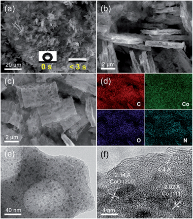
As described in the Experimental section, the host porous carbon cuboids featured with an ultra-hydrophilic surface and rich defects were generated through controlled carbonization of a new series of bipyridine-coordinated polymers. Afterwards, Co nanoparticles were further functionalized through wetness impregnation, finally obtaining the PCC–CoOx composite. Their morphological structures were examined by scanning electron microscopy (SEM) and transmission electron microscopy (TEM). Typical SEM (Fig. 1a and b) and TEM images (Fig. S1a and b†) of PCC reveal that the uniform and hierarchical carbon cuboids are randomly aggregated and overlapped with each other, with a rough surface and rich macropores. In addition, the high-resolution TEM image (Fig. S1c†) further reveals that the PCC is composed of randomly aggregated stacked-graphene sheets having a lot of defects, curvatures and edges. From the X-ray photoelectron spectroscopy (XPS) results (Fig. S1d–f†), it is clear that a considerable number of nitrogen- and oxygen-containing functional groups are bound to the carbon surface. Benefiting from such characteristics, the PCC sample shows superior hydrophilic properties with a high water capacity of up to 6.7 mmol g−1 at a relative humidity of 20% and 25 °C (see Fig. S2†), which is also confirmed by its ultra-fast wetting capability (Fig. 1a, inset). Thus, such a unique surface ensures that the PCC material has the ability to absorb Co2+ ions and further promote the homogeneous distribution of Co precursors during the wetness impregnation process. This finding is consistent with a previous study.38 SEM examination (Fig. 1c) shows that the PCC–CoOx sample after Co/CoO loading well maintains the hierarchical cuboid structure, demonstrating excellent structural stability. The corresponding energy dispersive X-ray spectroscopy elemental mapping results (Fig. 1d, Table S1†) verify the uniform distribution of all the elements (C, Co, O, and N) and high content of nitrogen (∼12.4 wt%) in the PCC–CoOx composite. The high-resolution TEM image (Fig. 1e and f) indicates that the formed nanoparticles with a size of around ∼6 nm are spatially well dispersed in the carbon matrix. The lattice fringes of ∼2.14 and ∼2.02 Å are ascribed to the (200) plane of CoO and the (111) plane of metallic Co, respectively. Besides, the presence of oriented multilayer domains and several graphene layers with an adjacent interlayer distance of ∼4.4 Å can also be recognized. It is evident that the CoO and Co nanoparticles are well incorporated into the N-doped carbon architecture and surrounded by a few graphene multilayers, which is beneficial for mechanical reinforcement and enhancement of the electrical conductivity of the composite.The porous characteristic of the PCC–CoOx sample was further probed by N2 physisorption (Fig. S3†). After loading Co/CoO nanoparticles, the PCC–CoOx sample exhibits a high specific surface area of ca. 381 m2 g−1 based on Brunauer–Emmett–Teller theory. The abrupt adsorption uptake in the high relative pressure region (P/P0 > 0.9) is ascribed to the presence of macropores, which is consistent with the SEM results. The pore size distribution determined by non-local density functional theory (NLDFT) based on adsorption branch corroborates the existence of small mesopores (2–6 nm) and a high density of micropores (1–2 nm). It is further found that the Co species are dispersed homogenously all over the structure, rather than blocking the entire pore. This promotes mass transfer during the reaction on the one hand, and ensures the effective penetration of the electrolyte inside the electrode on the other hand.
The X-ray diffraction (XRD) patterns of the PCC and PCC–CoOx composite are presented in Fig. 2a. Two broad diffraction peaks at around 29.3° and 50.8° are observed on the PCC sample, which correspond to the amorphous carbon framework. With CoOx addition, intense diffraction peaks at 43.1°, 50.1°, and 73.2° are assigned to CoO (JCPDS 70-2855), and the peaks at 52.1° and 60.7° are attributed to metallic Co (JCPDS 89-4307), which agrees well with the high-resolution TEM analysis, both indicating the coexistence of CoO and Co phases. Besides, Raman spectra (Fig. 2b) exhibit two characteristics of carbon peaks, the graphitic carbon peak (G band) located at ∼1593 cm−1 and the disordered carbon peak (D band) at ∼1371 cm−1.39–41 In the spectrum of the PCC–CoOx sample, four peaks are also observed at ∼673, ∼609, ∼516, and ∼473 cm−1, matching with A1g, F2g, F2g, and Eg modes of CoO.42 The peak area ratio between the D and G bands (ID/IG) is ∼1.11, which is higher than that of the amorphous PCC (∼0.95), suggesting that more structural disorder is introduced into the composite during the impregnation process and thermal treatment.
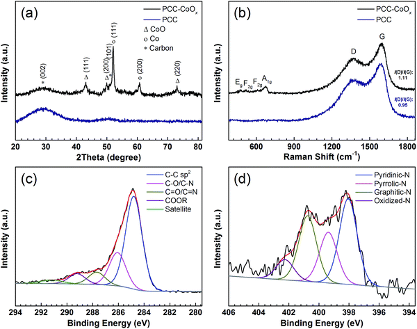 | ||
| Fig. 2 (a) XRD patterns, and (b) Raman spectra of the PCC and the PCC–CoOx materials. High-resolution XPS spectra of (c) C 1s and (d) N 1s for the PCC–CoOx sample. | ||
The XPS survey spectrum of the PCC–CoOx sample is given in Fig. S4a,† showing C, Co, O, and N peaks clearly. From the high-resolution C 1s peak in Fig. 2c, it can be derived that apart from most of the C–C sp2 bonds, other chemical states that bond to oxygen and nitrogen are also present such as (C–O/C–N (∼286.1 eV), C![[double bond, length as m-dash]](https://www.rsc.org/images/entities/char_e001.gif) O/C
O/C![[double bond, length as m-dash]](https://www.rsc.org/images/entities/char_e001.gif) N (∼287.7 eV), and COOR (∼289.2 eV)). The N 1s spectrum in Fig. 2d can be deconvoluted into four types of nitrogen species, including pyridinic-N (∼398.1 eV), pyrrolic-N (∼399.4 eV), graphitic-N (∼400.8 eV), and oxidized-N (∼402.3 eV) groups.43 These N-containing species (especially, pyridinic-N and pyrrolic-N) can serve as electrochemically active sites for enhancing the lithium storage properties.33,44,45 The Co 2p spectrum (Fig. S4b, see ESI†) further confirms the existence of CoO and metallic Co according to their characteristic binding energies.
N (∼287.7 eV), and COOR (∼289.2 eV)). The N 1s spectrum in Fig. 2d can be deconvoluted into four types of nitrogen species, including pyridinic-N (∼398.1 eV), pyrrolic-N (∼399.4 eV), graphitic-N (∼400.8 eV), and oxidized-N (∼402.3 eV) groups.43 These N-containing species (especially, pyridinic-N and pyrrolic-N) can serve as electrochemically active sites for enhancing the lithium storage properties.33,44,45 The Co 2p spectrum (Fig. S4b, see ESI†) further confirms the existence of CoO and metallic Co according to their characteristic binding energies.
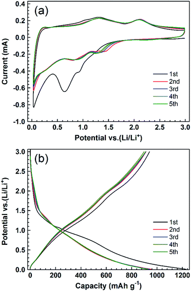
To evaluate the electrochemical performance of the obtained PCC–CoOx cuboid, two-electrode Swagelok-type half-cells were assembled with a lithium foil as the counter/reference electrode. Fig. 3a displays cyclic voltammetry (CV) profiles of the initial five cycles of the PCC–CoOx electrode at a scan rate of 0.2 mV s−1 over the voltage range from 0.01 to 3.0 V. Two reduction peaks appear at approximately ∼0.64 and ∼0.92 V in the first cathodic process, which correspond well to the initial reduction of CoO to Co and preliminary decomposition of the electrolyte to form a partially reversible solid electrolyte interphase (SEI).15,35 In the subsequent processes, these two peaks become weaker and shift to higher potential (one at ∼0.88 V and the other at ∼1.28 V) due to the drastic lithium driven, structural or textural modifications.16,46 There are two broad oxidation peaks in the following anodic processes. The one at ∼2.11 V is due to the reversible oxidation of Co to CoO, while the other one at ∼1.32 V is attributed to the partial decomposition of SEI components such as LiF, Li2CO3, and RCO2Li.47,48 These two redox reactions of lithium ions with the electrode are highly reversible. Thus, it is worthwhile to mention that the contribution from partial decomposition of SEI components to the total charge is considerable. It is believed to be a result of the presence of metallic Co acting as an efficient catalyst to activate new electrochemical decomposition of the electrolyte.32,35 The sloped profile at <0.4 V is also noted in repeated cathodic processes, confirming reversible Li uptake/release of the amorphous carbon. When the scanning rates are increased, both cathodic and anodic peaks become broader but still remain reversible (Fig. S5, see ESI†). This is a good indication that, besides the above-mentioned faradaic processes, capacitive processes become more relevant at higher sweep rates.34 Considering the structural features, we can speculate that the N-/O-decorated active sites at the edge of the graphene layers and the hierarchical architecture play pivotal roles in capacitive processes.36,44
Fig. 3b displays galvanostatic discharge/charge voltage profiles at a current density of 0.1 A g−1 for the first five cycles. The voltage profiles present sloping lines during both discharge and charge processes, in accordance with the broad peaks observed in CV curves. The first discharge and charge capacities calculated based on the total weight of the composite are approximately 1228 and 941 mA h g−1, respectively, with an initial coulombic efficiency of 76.6%. The irreversible capacity is assigned to the interfacial reactions between the electrode and the electrolyte, which could be improved by prelithiation in future studies. From the 2nd to the 5th cycle, there is no clear change in these curves, suggesting that the electrode is stable with reversible reactions during the following discharge/charge cycles.
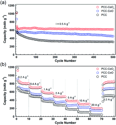
Both PCC–CoO without metallic Co incorporation and pure PCC anodes were also tested for comparison. As depicted in Fig. 4a, the PCC–CoOx electrode exhibits higher capacity and better cycling stability than the PCC–CoO and PCC electrodes under the same testing conditions. For the PCC–CoOx composite, the capacity just slightly decreases in the initial few cycles and then steadily increases back, preserving a high-level of capacity. After 500 discharge/charge cycles at a current density of 0.5 A g−1, the PCC–CoOx electrode still exhibits a high capacity of 618 mA h g−1, which is much higher than the theoretical capacity of graphite. In contrast, PCC–CoO and PCC electrodes only show low specific capacities of 452 and 312 mA h g−1, respectively. Clear capacity fading is observed in the PCC–CoO and the PCC, compared to the PCC–CoOx. Moreover, the PCC–CoOx anode exhibits excellent rate performance. As shown in Fig. 4b, the charge capacities of the PCC–CoOx electrode are 791, 694, 567, 475, 375, and 300 mA h g−1 at 0.2, 0.5, 1, 2, 5, and 10 A g−1, respectively. Even at an extremely high current density of 20 A g−1, a favourable capacity of 195 mA h g−1 is still maintained, which is 52.4% of the theoretical capacity of graphite. Importantly, after decreasing the current density back to 0.2 A g−1, the capacity recovers rapidly to 833 mA h g−1. The results suggest that the PCC–CoOx composite remains exceedingly stable even under high rate cycling. In contrast, both the PCC–CoO anode without the metallic Co phase and the PCC anode show inferior rate capability and lower reversible capacity. Therefore, it is obvious that the enhanced lithium storage performance has a close relationship with the addition of metallic Co nanoparticles. On the one hand, the highly conductive metallic Co nanoparticles attached tightly to the CoO nanoparticles increase the electrical conductivity of the composite. On the other hand, they function as effective catalysts to promote the reversible conversion of some SEI components, leading to a novel lithium storage mechanism and good rate capability.32,34,35 However, further in-depth investigations are needed in future studies.
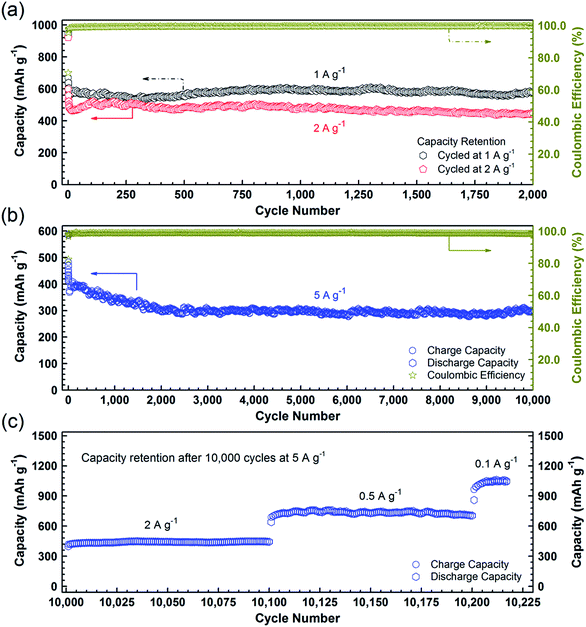
To further confirm the high durability of the PCC–CoOx composite, galvanostatic discharge/charge measurements were carried out at high current densities. Fig. 5a illustrates the long-cycling performance up to the 2000th cycle at 1 and 2 A g−1 (see Fig. S6a and b† for the individual discharge/charge curves). Compared to the cycling performance at 0.5 A g−1 (Fig. 4a), the PCC–CoOx anode experiences a more pronounced decrease in the capacity at the initial stage due to enhanced pulverization of the active material at high current densities. It can be seen that the charge capacity at 1 A g−1 still retains 580 mA h g−1 after 2000 cycles, which corresponds to 86.6% retention of the initial capacity. Furthermore, the coulombic efficiency is maintained at more than 99.7% after the initial few cycles, which agrees well with the durable cycling performance. Similarly, the cycling capability at 2 A g−1 is also excellent with a charge capacity of 442 mA h g−1 after 2000 cycles.
As a highlight, Fig. 5b displays an impressive cycling stability over 10![[thin space (1/6-em)]](https://www.rsc.org/images/entities/char_2009.gif) 000 cycles at 5 A g−1 with a capacity decay as low as ∼0.4% per cycle. Moreover, as shown in Fig. 5c, after the studies on ultralong-term cycling performance, the capacity is able to recover to 1050 mA h g−1 when the current density finally returns to 0.1 A g−1. A complete comparison of electrochemical properties of the cobalt oxide/carbon composites and other materials, summarized in Table S2,† demonstrates that the PCC–CoOx anode possesses excellent cycling stability over tens of thousands of cycles, much superior to those of metal oxide-based electrodes reported in the literature, although the mass specific capacities are lower than those of some other binder-free self-supported electrodes.4,6,12,15,22–25,27–29
000 cycles at 5 A g−1 with a capacity decay as low as ∼0.4% per cycle. Moreover, as shown in Fig. 5c, after the studies on ultralong-term cycling performance, the capacity is able to recover to 1050 mA h g−1 when the current density finally returns to 0.1 A g−1. A complete comparison of electrochemical properties of the cobalt oxide/carbon composites and other materials, summarized in Table S2,† demonstrates that the PCC–CoOx anode possesses excellent cycling stability over tens of thousands of cycles, much superior to those of metal oxide-based electrodes reported in the literature, although the mass specific capacities are lower than those of some other binder-free self-supported electrodes.4,6,12,15,22–25,27–29
Furthermore, in order to figure out the possible effects of the PCC–CoOx structure, the electrode was characterized after 500 cycles at 0.5 A g−1. Fig. 6a compares the electrochemical impedance spectroscopy results recorded before and after cycling. Based on the fitting analysis results, the charge transfer resistance (Rct) of the cycled electrode is estimated to be ∼57 Ω, which is much less than the value (∼190 Ω) of the fresh cell. This has been commonly observed for other metal oxide LIB electrodes, and herein could be due to the reduction of CoO into Co by the irreversible reactions. This behaviour is favourable for the enhancement of the electron kinetics in the electrode, which agrees well with the electrochemical results. More importantly, as illustrated in Fig. 6b–e, the morphology after 500 cycles of repeated lithiation/delithiation cycles has involved negligible changes when compared to that of the starting material, confirming the attractive structural stability of the electrode. These post-mortem studies prove the advantages of the well-designed PCC–CoOx composite, which are beneficial for achieving high rate performance.
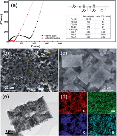 | ||
| Fig. 6 (a) Electrochemical impedance spectra of the PCC–CoOx electrode over the frequency range from 100 kHz to 0.01 Hz before and after 500 electrochemical cycles for the cycling performance test at 0.5 A g−1 in Fig. 4a. The inset is the equivalent circuit model of the studied system and the corresponding impedance parameters. (b and c) Ex situ SEM images, (d) corresponding elemental mapping images, and (e) TEM image of the PCC–CoOx electrode after 500 cycles at 0.5 A g−1. | ||
The above results clearly confirm that the PCC–CoOx anode has excellent cycling stability and superior rate capability, which can be attributed to the following characteristics. (i) The well-defined hierarchical porous structures of the CoOx incorporated carbon cuboids can effectively facilitate the penetration of an electrolyte inside the electrode, as well as alleviate stress and accommodate large volume changes during repeated lithiation/delithiation processes, thus improving the structural stability and cyclability of the electrode material. As illustrated in ESI, Fig. S7,† the electrolyte droplet can be well adsorbed in 7 s with a final contact angle of ca. 0, confirming the effective penetration of the electrolyte inside the PCC–CoOx material. (ii) The highly conductive metallic Co nanoparticles not only increase the electrical conductivity of the composite, but also function as effective catalysts to activate the reversible conversion of some SEI components, leading to outstanding lithium storage with high rate capability. (iii) N-containing porous carbon with many defects and short graphene multilayers promotes electrical conductivity and electrochemical reactivity, which additionally contributes to the exceptional performance.
Conclusions
In summary, we have presented a model anode for LIBs based on a high-defect hydrophilic porous carbon cuboid with tightly anchored Co/CoO nanoparticles. The PCC–CoOx electrode exhibits high capacity, superior rate capability, and excellent cycling stability over 10![[thin space (1/6-em)]](https://www.rsc.org/images/entities/char_2009.gif) 000 cycles. As far as we know, this is the longest cycle life ever reported for cobalt oxide-based LIB anodes. This study provides a new perspective to engineer high-performance electrodes for LIBs through controlling the surface chemistry of carbon host materials. We believe that the findings in this work may advance the development of long-life, high-power rechargeable LIBs for energy storage applications.
000 cycles. As far as we know, this is the longest cycle life ever reported for cobalt oxide-based LIB anodes. This study provides a new perspective to engineer high-performance electrodes for LIBs through controlling the surface chemistry of carbon host materials. We believe that the findings in this work may advance the development of long-life, high-power rechargeable LIBs for energy storage applications.
Acknowledgements
The authors are grateful to Prof. Ryo Ishikawa and Prof. Hajime Shirai (Saitama University, Japan) for their technical support for the XPS measurements. X. Sun acknowledges the financial support from the China Scholarship Council (CSC). G.-P. Hao acknowledges the financial support from the Alexander von Humboldt Foundation.References
- M. V. Reddy, G. V. Subba Rao and B. V. R. Chowdari, Chem. Rev., 2013, 113, 5364–5457 CrossRef CAS PubMed
.
- J. B. Goodenough and K.-S. Park, J. Am. Chem. Soc., 2013, 135, 1167–1176 CrossRef CAS PubMed
.
- Y. Zhou, D. Yan, H. Xu, J. Feng, X. Jiang, J. Yue, J. Yang and Y. Qian, Nano Energy, 2015, 12, 528–537 CrossRef CAS
.
- G. Zhang, S. Hou, H. Zhang, W. Zeng, F. Yan, C. C. Li and H. Duan, Adv. Mater., 2015, 27, 2400–2405 CrossRef CAS PubMed
.
- Z. Zhu, S. Wang, J. Du, Q. Jin, T. Zhang, F. Cheng and J. Chen, Nano Lett., 2014, 14, 153–157 CrossRef CAS PubMed
.
- X. Zhou, Z. Dai, S. Liu, J. Bao and Y.-G. Guo, Adv. Mater., 2014, 26, 3943–3949 CrossRef CAS PubMed
.
- L. Su, Z. Zhou, X. Qin, Q. Tang, D. Wu and P. Shen, Nano Energy, 2013, 2, 276–282 CrossRef CAS
.
- W. Si, X. Sun, X. Liu, L. Xi, Y. Jia, C. Yan and O. G. Schmidt, J. Power Sources, 2014, 267, 629–634 CrossRef CAS
.
- J. Zhou, Q. Liang, A. Pan, X. Zhang, Q. Zhu, S. Liang and G. Cao, J. Mater. Chem. A, 2014, 2, 11029–11034 CAS
.
- X. Sun, W. Si, L. Xi, B. Liu, X. Liu, C. Yan and O. G. Schmidt, ChemElectroChem, 2015, 2, 737–742 CrossRef CAS
.
- J. Zhou, Y. Huang, X. Cao, B. Ouyang, W. Sun, C. Tan, Y. Zhang, Q. Ma, S. Liang, Q. Yan and H. Zhang, Nanoscale, 2015, 7, 7035–7039 RSC
.
- J. Jiang, Y. Li, J. Liu, X. Huang, C. Yuan and X. W. Lou, Adv. Mater., 2012, 24, 5166–5180 CrossRef CAS PubMed
.
- J. Wang, N. Yang, H. Tang, Z. Dong, Q. Jin, M. Yang, D. Kisailus, H. Zhao, Z. Tang and D. Wang, Angew. Chem., Int. Ed., 2013, 52, 6417–6420 CrossRef CAS PubMed
.
- C. Yuan, H. B. Wu, Y. Xie and X. W. Lou, Angew. Chem., Int. Ed., 2014, 53, 1488–1504 CrossRef CAS PubMed
.
- X. Sun, C. Yan, Y. Chen, W. Si, J. Deng, S. Oswald, L. Liu and O. G. Schmidt, Adv. Energy Mater., 2014, 4, 1300912 Search PubMed
.
- P. Poizot, S. Laruelle, S. Grugeon, L. Dupont and J.-M. Tarascon, Nature, 2000, 407, 496–499 CrossRef CAS PubMed
.
- S.-Z. Huang, Y. Cai, J. Jin, J. Liu, Y. Li, H.-E. Wang, L.-H. Chen, T. Hasan and B.-L. Su, J. Mater. Chem. A, 2016, 4, 4264–4272 CAS
.
- J. Liang, H. Hu, H. Park, C. Xiao, S. Ding, U. Paik and X. W. Lou, Energy Environ. Sci., 2015, 8, 1707–1711 CAS
.
- X. Sun, X. Wang, L. Qiao, D. Hu, N. Feng, X. Li, Y. Liu and D. He, Electrochim. Acta, 2012, 66, 204–209 CrossRef CAS
.
- L. Qiao, X. Wang, L. Qiao, X. Sun, X. Li, Y. Zheng and D. He, Nanoscale, 2013, 5, 3037–3042 RSC
.
- X. Sun, X. Wang, Y. Qin, X. Li, L. Qiao, N. Feng, D. Hu and D. He, Mater. Lett., 2012, 66, 193–195 CrossRef CAS
.
- H.-J. Qiu, L. Liu, Y.-P. Mu, H.-J. Zhang and Y. Wang, Nano Res., 2015, 8, 321–339 CrossRef CAS
.
- X. Zheng, G. Shen, Y. Li, H. Duan, X. Yang, S. Huang, H. Wang, C. Wang, Z. Deng and B.-L. Su, J. Mater. Chem. A, 2013, 1, 1394–1400 CAS
.
- K. Cao, L. Jiao, Y. Liu, H. Liu, Y. Wang and H. Yuan, Adv. Funct. Mater., 2015, 25, 1082–1089 CrossRef CAS
.
- Y. Sun, X. Hu, W. Luo and Y. Huang, J. Mater. Chem., 2012, 22, 13826–13831 RSC
.
- D. Li, L.-X. Ding, S. Wang, D. Cai and H. Wang, J. Mater. Chem. A, 2014, 2, 5625–5630 CAS
.
- X.-L. Huang, R.-Z. Wang, D. Xu, Z.-L. Wang, H.-G. Wang, J.-J. Xu, Z. Wu, Q.-C. Liu, Y. Zhang and X.-B. Zhang, Adv. Funct. Mater., 2013, 23, 4345–4353 CrossRef CAS
.
- M. Zhang, E. Uchaker, S. Hu, Q. Zhang, T. Wang, G. Cao and J. Li, Nanoscale, 2013, 5, 12342–12349 RSC
.
- Q. Guan, J. Cheng, X. Li, B. Wang, L. Huang, F. Nie and W. Ni, Sci. Rep., 2015, 5, 10017 CrossRef CAS PubMed
.
- F. D. Wu and Y. Wang, J. Mater. Chem., 2011, 21, 6636–6641 RSC
.
- Y. Fu, X. Li, X. Sun, X. Wang, D. Liu and D. He, J. Mater. Chem., 2012, 22, 17429–17431 RSC
.
- L. Su, Z. Zhou and P. Shen, J. Phys. Chem. C, 2012, 116, 23974–23980 CAS
.
- L. Qie, W.-M. Chen, Z.-H. Wang, Q.-G. Shao, X. Li, L.-X. Yuan, X.-L. Hu, W.-X. Zhang and Y.-H. Huang, Adv. Mater., 2012, 24, 2047–2050 CrossRef PubMed
.
- X. Sun, W. Si, X. Liu, J. Deng, L. Xi, L. Liu, C. Yan and O. G. Schmidt, Nano Energy, 2014, 9, 168–175 CrossRef CAS
.
- L. Zhang, P. Hu, X. Zhao, R. Tian, R. Zou and D. Xia, J. Mater. Chem., 2011, 21, 18279–18283 RSC
.
- K. Chang, D. Geng, X. Li, J. Yang, Y. Tang, M. Cai, R. Li and X. Sun, Adv. Energy Mater., 2013, 3, 839–844 CrossRef CAS
.
- S. H. Lee, S.-H. Yu, J. E. Lee, A. Jin, D. J. Lee, N. Lee, H. Jo, K. Shin, T.-Y. Ahn, Y.-W. Kim, H. Choe, Y.-E. Sung and T. Hyeon, Nano Lett., 2013, 13, 4249–4256 CrossRef CAS PubMed
.
- G.-P. Hao, N. R. Sahraie, Q. Zhang, S. Krause, M. Oschatz, A. Bachmatiuk, P. Strasser and S. Kaskel, Chem. Commun., 2015, 51, 17285–17288 RSC
.
- X. Sun, X. Wang, N. Feng, L. Qiao, X. Li and D. He, J. Anal. Appl. Pyrolysis, 2013, 100, 181–185 CrossRef CAS
.
- L. Qiao, X. Sun, Z. Yang, X. Wang, Q. Wang and D. He, Carbon, 2013, 54, 29–35 CrossRef CAS
.
- G.-P. Hao, A.-H. Lu, W. Dong, Z.-Y. Jin, X.-Q. Zhang, J.-T. Zhang and W.-C. Li, Adv. Energy Mater., 2013, 3, 1421–1427 CrossRef CAS
.
- H. C. Choi, Y. M. Jung, I. Noda and S. B. Kim, J. Phys. Chem. B, 2003, 107, 5806–5811 CrossRef CAS
.
- G.-P. Hao, G. Mondin, Z. Zheng, T. Biemelt, S. Klosz, R. Schubel, A. Eychmüller and S. Kaskel, Angew. Chem., Int. Ed., 2015, 54, 1941–1945 CrossRef CAS PubMed
.
- F. Zheng, Y. Yang and Q. Chen, Nat. Commun., 2014, 5, 5261 CrossRef CAS PubMed
.
- Z.-S. Wu, W. Ren, L. Xu, F. Li and H.-M. Cheng, ACS Nano, 2011, 5, 5463–5471 CrossRef CAS PubMed
.
- X. Wang, L. Qiao, X. Sun, X. Li, D. Hu, Q. Zhang and D. He, J. Mater. Chem. A, 2013, 1, 4173–4176 CAS
.
- L. Su, Y. Zhong and Z. Zhou, J. Mater. Chem. A, 2013, 1, 15158–15166 CAS
.
- L. Su, Z. Zhou and P. Shen, Electrochim. Acta, 2013, 87, 180–185 CrossRef CAS
.
Footnote |
| † Electronic supplementary information (ESI) available. See DOI: 10.1039/c6ta03098j |
| This journal is © The Royal Society of Chemistry 2016 |

