Binary nickel–iron nitride nanoarrays as bifunctional electrocatalysts for overall water splitting†
Ming
Jiang
,
Yingjie
Li
,
Zhiyi
Lu
*,
Xiaoming
Sun
* and
Xue
Duan
State Key Laboratory of Chemical Resource Engineering, Beijing University of Chemical Technology, Beijing 100029, China. E-mail: sunxm@mail.buct.edu.cn; zhiyilu1124@gmail.com
First published on 21st January 2016
Abstract
Electrochemical water splitting provides a facile method for high-purity hydrogen production, but electro-catalysts with a stable bifunctional activity towards both oxygen and hydrogen evolution have been rarely developed. Herein we report a Fe2Ni2N material with a vertically aligned nanoplate array architecture as a bifunctional catalyst for overall water splitting in an alkaline environment. This advanced catalyst affords small onset overpotentials and fast current density increase, resulting in an excellent water splitting performance (requiring 1.65 V for achieving 10 mA cm−2), superior to the combination of benchmark noble metal catalysts.
The development of sustainable energy resources is of great importance to solve the increasing global demand for energy and the environmental pollution caused by burning of fossil fuels.1–4 Water splitting driven by electricity or sunlight is widely considered to be critical for renewable hydrogen production.1 The key to reduce energy supply and maximize the water splitting efficiency lies in the electro-catalyst screening for the oxygen evolution reaction (OER) and the hydrogen evolution reaction (HER).5–7 Currently, noble metal based electro-catalysts (e.g. IrO2 and Pt) are identified to be the most active for these electro-catalyses, but the terrestrial scarcity and high cost of noble metals make them less attractive for commercial applications.8–10 To address this issue, a variety of catalysts have been investigated with comparable activity as cheap alternatives, including metal oxides,11,12 hydroxides,13 and selenides14 for OER, and metal alloys,15 carbides,16 sulfides,17 phosphides18 and nitrides19 for HER. However, the afore-mentioned electro-catalysts are usually active for a single half reaction because of the instability of the catalysts under the other half reaction conditions (e.g. positive or negative potential). Therefore, developing bifunctional electrocatalysts for water splitting is rarely achieved and still remains a big challenge.20–22
In this study, we demonstrated mesoporous Fe2Ni2N nanoplate arrays (NPAs) vertically grown on Ni foam as bifunctional catalysts for overall water splitting. The porous nanoarray architecture not only provided a large electrochemical active surface area for ion diffusion, but also facilitated fast electron transportation due to a direct contact with the substrate. As a result, the NiFe-based nitride catalyst exhibited excellent activity toward both OER and HER, which allowed the construction of an efficient alkaline electrolyzer (requiring 1.65 V for achieving 10 mA cm−2) using this bifunctional catalyst, superior to the electrolyzer assembled by noble metal catalysts. Moreover, this electrolyzer showed prominent stability (retaining 94.5% of initial current for 10 h), possibly due to the stability of the Fe2Ni2N catalyst under both OER and HER conditions.
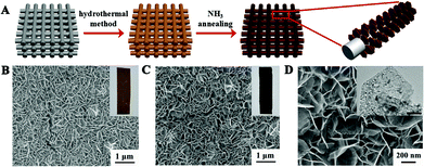
The synthesis of Fe2Ni2N NPAs involved two steps, as shown in Fig. 1A. A NiFe-based precursor (NiFe layered double hydroxides, denoted as NiFe-LDHs) with a nanoplate structure (Fig. 1B) was firstly synthesized by a hydrothermal method.13 Afterwards, the precursor was directly calcined at 380 °C under an NH3 atmosphere to obtain Fe2Ni2N NPAs. As a comparison, NiFe-based oxide nanoplates were obtained by direct calcination of the NiFe-based precursor nanoplates in air (Fig. S1†). Scanning electron microscopy (SEM, Fig. 1C) demonstrated that the nanoplates with an average size of 0.5 μm and thickness of 20 nm were uniformly covered on the substrate, preserving the morphology of the NiFe-based precursor (Fig. 1B). However, the color of the final product changed from brown (Fig. 1B, inset) to black (Fig. 1C, inset), indicating a successful conversion. High resolution SEM showed that the final sample is porous with a rough surface (Fig. 1D), which arises from the gas release and dehydration of the precursor during annealing. Meanwhile, the transmission electron microscopy (TEM) image presented in the inset of Fig. 1D also confirmed the nanoporous nature of NiFe nitride.
The structural information of the nitrided sample was investigated by X-ray diffraction (XRD, Fig. 2A), which showed a series of Bragg reflections matching well with Fe2Ni2N (JCPDF: 50-1350). The high-resolution TEM (HRTEM) image of the individual Fe2Ni2N nanoplate demonstrated a well-resolved lattice fringe of 0.217 nm, corresponding to the diffraction of a (111) plane (Fig. 2B). The energy dispersive X-ray spectroscopy (EDS) elemental mapping image proved the existence of N and indicated a homogeneous elemental distribution throughout the nanoplates, as shown in Fig. S2.†
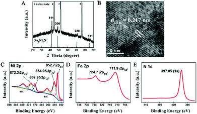 | ||
| Fig. 2 (A) XRD pattern and (B) HRTEM images of the Fe2Ni2N NPAs; (C), (D) and (E), XPS spectra of Ni 2p, Fe 2p, and N 1s peaks of Fe2Ni2N NPAs. | ||
X-ray photoelectron spectroscopy (XPS) was used to investigate the oxidation states of elements in the nanoplate surface. For the NiFe-based oxide nanoplate, as shown in Fig. S3,† the Ni 2p spectrum showed two peaks at 855.45 and 872.55 eV corresponding to the +2 oxidation state of Ni.23 The peaks at 712.4 and 724.9 eV of the Fe 2p spectrum demonstrated that the Fe species were mainly in their oxidation states of +3.12 After thermal treatment under an NH3 atmosphere, the Ni 2p XPS peaks of Fe2Ni2N can be deconvoluted into four peaks (Fig. 2C). Similar to the NiFe-based oxide, peaks at 854.95 (2p3/2) and 872.3 (2p1/2) eV in the Ni 2p spectra of Fe2Ni2N revealed the existence of Ni2+, while the other two peaks at 852.7 (2p3/2) and 869.95 (2p1/2) eV suggested a metallic state of nickel, indicating that Ni was partially reduced by the thermal treatment of NH3.24 To rule out the possible contribution from the substrate, we have synthesized Fe2Ni2N nanoplate arrays on carbon fiber paper and observed the XPS data (Fig. S4†), which showed similar XPS peaks as the sample grown in Ni foam, indicating that the metallic Ni peak cannot be attributed to the exposure of the substrate. For the other transition metal component of Fe species, thermal treatment showed no obvious reduction of Fe relative to Ni components (Fig. 2D); however, it did shift the Fe 2p3/2 XPS spectrum to a lower binding energy of 0.5 eV which was also found for the Ni components. As nitrogen has a lower electronegativity than oxygen, the electron density outside the metal ions in Fe2Ni2N is higher than the NiFe-based oxide. Thus, the binding energies of 2p3/2 peaks of both Ni and Fe were shifted to lower values (Fig. S3†).25 The N 1s region showed a strong peak near 397.05 eV, which was consistent with the N environment in metal nitride (Fig. 2E).26
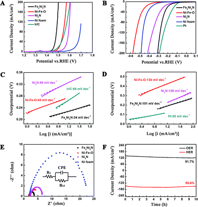
The OER activity of Fe2Ni2N NPAs was firstly evaluated in O2 saturated 1 M KOH solution. Fig. 3A demonstrates the polarization curve of Fe2Ni2N with a scan rate of 1 mV s−1. For comparison, the NiFe-based oxide, Ni3N NPAs (the synthesis method and characterization can be seen in ESI, Fig. S5†) and pristine nickel foam were also examined under the same conditions. Because the as-measured reaction currents did not directly reflect the intrinsic behavior of the catalysts due to the effect of ohmic resistance, an iR-correction was applied for further analysis.27 It is obvious in Fig. 3A that the current density of Fe2Ni2N was indeed higher than that of the NiFe-based oxide, Ni3N NPAs and the pristine Ni foam under a certain applied potential, and also showed a much earlier onset potential (∼1.43 V vs. RHE). Notably, the OER activity of Fe2Ni2N NPAs was even better than the 20 wt% Ir/C catalyst, which afforded an onset potential of ∼1.47 V. Furthermore, the Tafel slope using a Fe2Ni2N NPA electrode was measured to be 34 mV dec−1 (Fig. 3C), which was smaller than the NiFe-based oxide (43 mV dec−1), Ni3N NPAs (56 mV dec−1) and the Ir/C catalyst (69 mV dec−1). The different performance may be caused by the difference in the intrinsic activity and resistance of materials and of charge transfer on the surface.28 All the above results demonstrated that the Fe2Ni2N NPAs possess a higher intrinsic electrocatalytic activity for the OER than that of the NiFe-based oxide and commercial Ir/C. The better performance of nickel–iron nitride than nickel-nitride indicated the advantages of a binary metal compound in this case. The high activity towards the OER (low onset potential and the small Tafel slope) of Fe2Ni2N could be rationalized as follows: (1) the incorporation of nitrogen made the electrode structure more disordered, which could provide more active sites;19 (2) the porosity of the NPAs not only led to the exposure of more active sites but also facilitated sufficient transport of reactants and products.29 To further prove the electrocatalytic OER performance of Fe2Ni2N, electrochemical impendence spectroscopy measurement was carried out to study the electrode kinetics under OER conditions. Nyquist plots (Fig. 3E) revealed an extremely decreased charge transfer resistance (Rct in the equivalent circuit) for Fe2Ni2N in comparison with the NiFe-based oxide, Ni3N NPAs and pristine Ni foam, indicating a much faster electron transfer process during the electrochemical reaction.30 This may be associated with the porous structure and better electrical conductivity of metal nitride than oxide.31
In order to minimize the whole overpotential of water splitting, it is not sufficient to have a good OER performance for a bifunctional catalyst. Therefore, we assessed the catalytic activity of the Fe2Ni2N NPAs for the HER under the same basic conditions (Fig. 3B). For comparison, the NiFe-based oxide, Ni3N NPAs, pristine Ni foam and Pt were also studied here. As expected, Pt showed superior HER activity with a negligible overpotential. Although the NiFe-based oxide, Ni3N NPAs, and pristine Ni foam showed poor HER activities, Fe2Ni2N NPAs exhibited an onset overpotential as low as 110 mV, and a negative potential caused a rapid rise of the cathodic current, for example, only 180 mV of overpotential was required for achieving 10 mA cm−2, suggesting that the Fe2Ni2N NPAs acted as a high-performance electrocatalyst for generating hydrogen from water. The smaller Tafel slopes for Fe2Ni2N NPAs than that for the NiFe-based oxide and Ni3N NPAs further confirmed the better performance towards the HER of the binary metal nitride sample. All three samples exhibited classical Volmer–Heyrovsky behavior (ca. 120 mV dec−1, Fig. 3D), which is similar to most Ni-based materials in alkaline water electrolysis.19
The stabilities of the Fe2Ni2N NPAs for both OER and HER were investigated under a constant voltage. When operating the OER and HER at certain applied potentials, stable corresponding current densities were observed with negligible degradation (8.3% for OER and 4.4% for HER, respectively) after 10 h of continuous testing (Fig. 3F), revealing the high stability as well as a high Faraday efficiency. After a durability test, the performance of the catalyst in both OER and HER was maintained with almost no noticeable difference (Fig. S6†). The high electrochemical stability was attributed to the outstanding stability of Fe2Ni2N under both positive and negative potentials, as revealed by the XRD patterns (Fig. S7†).
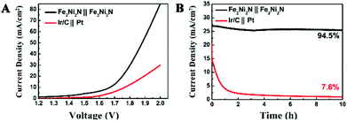
To illustrate practical relevance, the overall water splitting performance was investigated in a two-electrode setup using the same material as both cathode and anode in 1 M KOH solution. The linear sweep voltammetry showed that the electrolysis process proceeded at an applied potential of 1.6 V vs. RHE (Fig. 4A), and a current density of 10 mA cm−2 was obtained at about 1.65 V, which illustrated a combined overpotential of only about 400 mV for the HER and OER, superior to the electrolyzer assembled by Ni3N NPAs (Fig. S8†). Moreover, this electrolyzer also outperformed the electrolyzer assembled by Ir/C and Pt electrodes as an anode and cathode (requiring 1.78 V for achieving 10 mA cm−2), respectively. The stability of the catalyst is of importance because a practical water-splitting device should ideally last for a long time. The stability of the nitride catalyst electrode was operated under an applied potential of 1.8 V (Fig. 4B), and only a slight degradation over a 10 h testing was observed. The superb water splitting efficiency and good stability allowed the Fe2Ni2N NPAs as one of the most excellent bifunctional electrocatalytic candidates for overall water splitting.
The above results clearly demonstrate the excellent bifunctional performance of Fe2Ni2N NPAs, which can be attributed to the following reasons. Firstly, the porous nanoarray architecture as well as the mesoporous nanostructure can offer a large surface area, enhancing ion diffusion and providing more active sites for electrocatalysis.32 The Brunauer–Emmett–Teller (BET) measurement results demonstrate that the surface area of Fe2Ni2N NPAs is ∼4 times higher than that of nickel foam (Fig. S9 and Table S1†), indicating the effectiveness of constructing a porous structure. Secondly, the direct growing nature of the transition metal nitride facilitates the electron transportation through the current collector to the active sites, thus accelerating the surface chemical reaction. Moreover, since the transition metal nitride has unique electronic structure,31 high electrocatalytic activity33 and high stability in both positive and negative potentials, this kind of material demonstrates stable and outstanding bifunctional performance.
In summary, a nanoporous Fe2Ni2N NPA was prepared by converting NiFe-LDH under an NH3 atmosphere, which demonstrated its high activity as a bifunctional catalyst for overall water splitting in alkaline medium. Due to the unique material and structural advantages, the Fe2Ni2N NPA electrode presented excellent catalytic activity with a small onset overpotential (ca. 200 mV for OER and 110 mV for HER), low Tafel slope (34 mV dec−1 for OER and 101 mV dec−1 for HER) and prominent electrochemical durability. This kind of catalyst can be directly utilized as a catalyst for both anode and cathode with superior efficiency and strong robustness. These findings can inspire a variety of opportunities for designing other binary or trinary transition metal nitrides towards the full electrocatalytic splitting reaction of water, as well as in other electrochemical devices.
This work was supported by the National Natural Science Foundation of China, the Program for Changjiang Scholars and Innovative Research Team in University. This work was also supported by the long-term subsidy mechanism from the Ministry of Finance and the Ministry of Education of PRC.
Notes and references
- Y. Jiao, Y. Zheng, M. Jaroniec and S. Z. Qiao, Chem. Soc. Rev., 2015, 44, 2060–2086 RSC.
- D. Kong, J. J. Cha, H. Wang, H. R. Lee and Y. Cui, Energy Environ. Sci., 2013, 6, 3553 CAS.
- Z. L. Wang, D. Xu, J. J. Xu and X. B. Zhang, Chem. Soc. Rev., 2014, 43, 7746–7786 RSC.
- M. S. Faber and S. Jin, Energy Environ. Sci., 2014, 7, 3519–3542 CAS.
- M. G. Walter, E. L. Warren, J. R. McKone, S. W. Boettcher, Q. Mi, E. A. Santori and N. S. Lewis, Chem. Rev., 2010, 110, 6446–6473 CrossRef CAS PubMed.
- Y. Zhu, W. Zhou, Y. Chen, J. Yu, M. Liu and Z. Shao, Adv. Mater., 2015, 27, 7150–7155 CrossRef CAS PubMed.
- T. R. Cook, D. K. Dogutan, S. Y. Reece, Y. Surendranath, T. S. Teets and D. G. Nocera, Chem. Rev., 2010, 110, 6474–6502 CrossRef CAS PubMed.
- S. Marini, P. Salvi, P. Nelli, R. Pesenti, M. Villa, M. Berrettoni, G. Zangari and Y. Kiros, Electrochim. Acta, 2012, 82, 384–391 CrossRef CAS.
- R. Subbaraman, D. Tripkovic, D. Strmcnik, K.-C. Chang, M. Uchimura, A. P. Paulikas, V. Stamenkovic and N. M. Markovic, Science, 2011, 334, 1256–1260 CrossRef CAS PubMed.
- Y. Li, H. Zhang, T. Xu, Z. Lu, X. Wu, P. Wan, X. Sun and L. Jiang, Adv. Funct. Mater., 2015, 25, 1737–1744 CrossRef CAS.
- Z. Lu, H. Wang, D. Kong, K. Yan, P. C. Hsu, G. Zheng, H. Yao, Z. Liang, X. Sun and Y. Cui, Nat. Commun., 2014, 5, 4345 CAS.
- K. Fominykh, P. Chernev, I. Zaharieva, J. Sicklinger, G. Stefanic, M. Döblinger, A. Müller, A. Pokharel, S. Böcklein and C. Scheu, ACS Nano, 2015, 9, 5180–5188 CrossRef CAS PubMed.
- Z. Lu, W. Xu, W. Zhu, Q. Yang, X. Lei, J. Liu, Y. Li, X. Sun and X. Duan, Chem. Commun., 2014, 50, 6479–6482 RSC.
- L. Liang, H. Cheng, F. Lei, J. Han, S. Gao, C. Wang, Y. Sun, S. Qamar, S. Wei and Y. Xie, Angew. Chem., Int. Ed., 2015, 54, 12004–12008 CrossRef CAS PubMed.
- X. Wang, R. Su, H. Aslan, J. Kibsgaard, S. Wendt, L. Meng, M. Dong, Y. Huang and F. Besenbacher, Nano Energy, 2015, 12, 9–18 CrossRef CAS.
- L. Liao, S. Wang, J. Xiao, X. Bian, Y. Zhang, M. D. Scanlon, X. Hu, Y. Tang, B. Liu and H. H. Girault, Energy Environ. Sci., 2014, 7, 387–392 CAS.
- H. Zhang, Y. Li, T. Xu, J. Wang, Z. Huo, P. Wan and X. Sun, J. Mater. Chem. A, 2015, 3, 15020–15023 CAS.
- E. J. Popczun, J. R. McKone, C. G. Read, A. J. Biacchi, A. M. Wiltrout, N. S. Lewis and R. E. Schaak, J. Am. Chem. Soc., 2013, 135, 9267–9270 CrossRef CAS PubMed.
- M. Shalom, D. Ressnig, X. Yang, G. Clavel, T. P. Fellinger and M. Antonietti, J. Mater. Chem. A, 2015, 3, 8171–8177 CAS.
- H. Wang, H. W. Lee, Y. Deng, Z. Lu, P. C. Hsu, Y. Liu, D. Lin and Y. Cui, Nat. Commun., 2015, 6, 7261 CrossRef CAS PubMed.
- M. Ledendecker, S. Krick Calderon, C. Papp, H. P. Steinruck, M. Antonietti and M. Shalom, Angew. Chem., Int. Ed., 2015, 127, 12538–12542 CrossRef.
- M. Gong, W. Zhou, M. C. Tsai, J. Zhou, M. Guan, M. C. Lin, B. Zhang, Y. Hu, D. Y. Wang, J. Yang, S. J. Pennycook, B. J. Hwang and H. Dai, Nat. Commun., 2014, 5, 4695 CrossRef CAS PubMed.
- L. Qian, Z. Lu, T. Xu, X. Wu, Y. Tian, Y. Li, Z. Huo, X. Sun and X. Duan, Adv. Energy Mater., 2015, 5, 1500245 Search PubMed.
- L.-S. Hsu and R. S. Williams, J. Phys. Chem. Solids, 1994, 55, 305–312 CrossRef CAS.
- Z. Peng, D. Jia, A. M. Al-Enizi, A. A. Elzatahry and G. Zheng, Adv. Energy Mater., 2015, 5, 1402031 Search PubMed.
- D. D. Vaughn Ii, J. Araujo, P. Meduri, J. F. Callejas, M. A. Hickner and R. E. Schaak, Chem. Mater., 2014, 26, 6226–6232 CrossRef.
- P. Jiang, Q. Liu, Y. Liang, J. Tian, A. M. Asiri and X. Sun, Angew. Chem., Int. Ed., 2014, 53, 12855–12859 CrossRef CAS PubMed.
- A. Singh and L. Spiccia, Coord. Chem. Rev., 2013, 257, 2607–2622 CrossRef CAS.
- J. Tian, Q. Liu, A. M. Asiri and X. Sun, J. Am. Chem. Soc., 2014, 136, 7587–7590 CrossRef CAS PubMed.
- T. Wang, L. Liu, Z. Zhu, P. Papakonstantinou, J. Hu, H. Liu and M. Li, Energy Environ. Sci., 2013, 6, 625–633 CAS.
- K. Xu, P. Chen, X. Li, Y. Tong, H. Ding, X. Wu, W. Chu, Z. Peng, C. Wu and Y. Xie, J. Am. Chem. Soc., 2015, 137, 4119–4125 CrossRef CAS PubMed.
- R. Wu, J. Zhang, Y. Shi, D. Liu and B. Zhang, J. Am. Chem. Soc., 2015, 137, 6983–6986 CrossRef CAS PubMed.
- W. F. Chen, K. Sasaki, C. Ma, A. I. Frenkel, N. Marinkovic, J. T. Muckerman, Y. Zhu and R. R. Adzic, Angew. Chem., Int. Ed., 2012, 51, 6131–6135 CrossRef CAS PubMed.
Footnote |
| † Electronic supplementary information (ESI) available: Detailed experimental procedure, optical and SEM images, high-resolution TEM image, EDX mapping, XPS spectra, polarization curves, XRD patterns and BET results. See DOI: 10.1039/c5qi00232j |
| This journal is © the Partner Organisations 2016 |

