Recent progress in the preparation of polyaniline nanostructures and their applications in anticorrosive coatings
Zhifei Tian,
Haojie Yu*,
Li Wang*,
Muhammad Saleem,
Fujie Ren,
Pengfei Ren,
Yongsheng Chen,
Ruoli Sun,
Yubiao Sun and
Liang Huang
State Key Laboratory of Chemical Engineering, Department of Chemical and Biological Engineering, Zhejiang University, Hangzhou 310027, China. E-mail: hjyu@zju.edu.cn; opl_wl@dial.zju.edu.cn; tian.zhifei@live.cn; chemist.saleem786@gmail.com; Iamrenfujie@126.com; 1989guoyunyu@163.com; josephchan0314@gmail.com; sun_ruoli@163.com; sunyu.biao@163.com; a314630828@163.com; Fax: +86-571-8795-1612; Tel: +86-571-8795-3200
First published on 30th June 2014
Abstract
Research on composites/blends containing polyaniline (PANI) has attracted numerous scientists and engineers due to their excellent adhesion and anticorrosive properties. Nano-structured PANI composites and matrix resins play a key role in physical and anticorrosive performance. This paper reviews the synthesis, growth mechanisms and corrosion application with different resin coatings of PANI-based nano-composites. It also highlights the failures of corrosion protection and methods and suggestions to improve it.
1. Introduction
Corrosion can lead to enormous economic costs and damage to modern industrial societies, which have a bad impact on humans and the surrounding environment. It has been reported that corrosion consumes more than 3% of the gross domestic product (GDP) of the world annually.1–3One of the most commonly practiced techniques to prevent metals from corrosion is to apply anticorrosive paints on their surfaces. Commonly used anticorrosive paints, such as epoxy, polyurethane, polyester, etc., are formulated from thermosetting resins, which are not long-lasting. Once a scratch or hole forms in the coating, the corrosive easily attacks the matrices. To improve their anticorrosion performance, anticorrosive coatings must contain corrosion inhibitors such as lead compounds and chromate pigments.4 However, due to the adverse effects of heavily used chromium and lead, the environment protection authority and other environmental organizations mandate the elimination of their use as pigments for anticorrosion paint. Sacrificial coatings that use zinc particles as pigments have been designed for heavy duty protection to minimize pollution. However, this type of coating is quite easily corroded due to its poor physico-chemical properties, which significantly limits its use in the shipping industry.5
Conducting polymers gained much attention during the past two decades because of their environmentally friendly behavior as well as their unusual corrosion inhibiting action for metals.6–12 Among these conducting polymers, polyaniline is considered to be one of the best anticorrosive materials13–15 not only because of its unique redox tunability, environmental stability and simple acid–base doping–dedoping process,16 but also because passivation of oxide layer between metal and coating is induced by PANI, which protects the metal from further corrosive attack.17 PANI nanoparticles are of great interest to researchers because of their unique quantum size effect, small size effect and surface effect. They have demonstrated enhanced performance in applications such as corrosion protection,18–22 electrochromic devices,23 sensors,24 biomimetic scaffolds,25 energy storage26–28 and supercapacitors.29–31 Therefore, it is of both great technological and scientific interest to investigate anticorrosive composites/blends containing PANI nanostructure. Although several articles on PANI32–35 have been devoted to the preparation of PANI nanofibers and nanotubes, in this review we narrow down our discussion on the recent preparation of various PANI nanostructures and their applications on improving adhesion and hydrophobicity, as well as the anticorrosion of coatings.
2. Preparation of PANI nanostructures
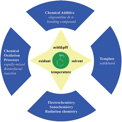
There are various methods for preparing nanoscale PANI such as heterophase interfacial, solution, self-assembling and electrochemical polymerizations.36–39 Fig. 1 shows a schematic summary of the oxidation of aniline, which also presents some significant factors affecting the morphology alone or synergism during the synthesis process. In addition to the core parameters (yellow color) for oxidizing aniline, to tailor the type of desired nanostructure, other reaction parameters and processes (blue color) should be taken into consideration.40,41 These parameters and processes include chemical additives introduced to the oxidation, type of template used, polymerization and equipment employed.42 Although the processes for producing PANI nanostructures are quite complicated, they can be divided into two routes: those that rely on external templates to induce the growth of nanostructure and those that do not.43 Corrosion chemists are trying to synthesize well-designed PANI composites to realize superhydrophobic surface and various nanostructures.44 Template synthesis is an efficient method for producing superior anticorrosion nanoscale PANI composites. As the most straightforward method for synthesizing PANI nanostructures, the template route includes soft-template and hard-template methods. The former, also named as the self-assembly method,45 relies on micelles formed by surfactants to confine the polymerization of PANI into one-dimensional nanostructures. Compared to the soft-template synthesis, the monomer or its salt forms micelles by itself in the non-template synthesis. The hard-template employs some particles as a scaffold such that PANI can grow on the surface of particles to acquire a certain morphology.Scheme 1 shows certain initial oligoanilines to synthesize PANI.46 Reaction through the ortho position can lead to further oxidation, which produces phenazine-like moieties along the backbone of the polymer. Aniline reacting through tail-to-tail coupling will produce benzidine moieties, and through head-to-head coupling it will produce azobenzene. Furthermore, ortho-coupled units may undergo intramolecular cyclization to produce phenazine structures, which play the role of nucleates in chain propagation.47 The relatively flat molecular structure of the phenazine moiety makes them hydrophobic and allows them to maintain one-dimensional nanostructures stable by π–π interactions. They can deposit on various surfaces to become orderly arranged in the nanostructure with outward benzene rings.48 Since they form a basis for the proposed self-assembly processes, these possible reactions of aniline during its initial stages of oxidation are crucial for understanding several mechanisms of nanostructure formation.49–51 The hydrophobic property and the various nanostructures are crucial for corrosion protection,52 making the formation of phenazine-containing structure an important part of the synthesis of PANI composites. Then, a series of organizations of nucleates, including disordered self-assembly, stacking, adsorption at polymer chains, or adsorption on immersed surfaces occurs exclusively, successively or simultaneously, depending on the experimental conditions.42,53
 | ||
| Scheme 1 Different initial stages of oxidation to obtain PANI.46 | ||
The reversible acid–base, doping–dedoping, oxidation–reduction chemistry of polyaniline is shown in Scheme 2.54 Leucoemeraldine, known as the fully reduced form of polyaniline, can be fully oxidized to form pernigraniline or half-oxidized to form emeraldine. The emeraldine base (EB) form of polyaniline is electrically insulating, and can be doped with a strong acid to give the electrically conducting emeraldine salt (ES) form of PANI. By adding a strong base, ES can be reversed to electrically insulating EB. This reversible conductivity achieved by doping can be applied in actuators and batteries;32 the unique redox tenability plays a constructive role in keeping the metal in the passivation state.55
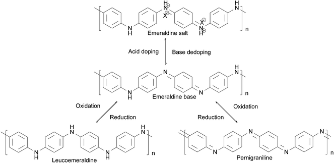 | ||
| Scheme 2 Oxidation–reduction reaction of PANI.54 | ||
Nucleates and aniline are sensitive to slight changes during the reaction condition, which leads to PANI's propensity for forming numerous different structures. Schematic diagrams of processes for the preparation of different morphologies of PANI composites are shown in Fig. 2. In particular, the diversity of PANI nanostructures offers the possibility of enhanced performance wherever a high interfacial area is required between the atmosphere and PANI.56 For example, PANI nanostructures display much higher anticorrosion properties and better impact toughness relative to their conventional bulk counterparts in anticorrosive coatings due to higher effective surface areas and better contact with metals or resins.57 Different PANI-based composites with various morphologies applied in specific circumstances are shown in Table 1.
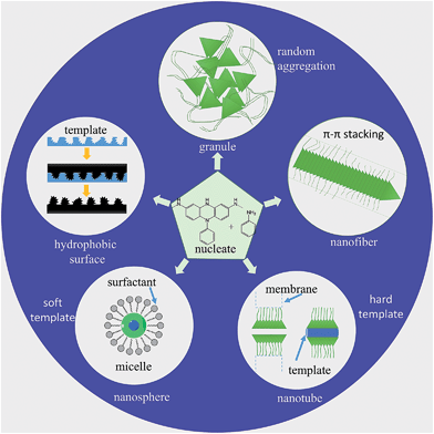 | ||
| Fig. 2 Schematic illustration of nucleates and monomer of aniline to produce different types of PANI nanostructures. | ||
| Different morphology of PANI-based | Composition of corrosion inhibitora [Ref.] | Doped acidb | Methods of composite preparation | Metal used | Corrosive medium |
|---|---|---|---|---|---|
| a ND–PANI, nano-diamond–polyaniline; PANI–CN, polyaniline clay nano-composite; PANI–MWCNT, multi-wall carbon nanotube–polyaniline; PANI/P-PVA, polyaniline/partially phosphorylated poly(vinyl alcohol); HEE, hydrophobic electroactive epoxy; SEPI, superhydrophobic electroactive polyimide; ACAT, amine-capped aniline trimer.b CSA, camphor sulfonic acid; DBSA, dodecylbenzene sulfonic acid. | |||||
| Granules | ND–PANI6 | HCl | In situ polymerization | Steel and aluminum | HCl |
| PANI–CN85 | — | Ultrasonic oxidative polymerization | Carbon steel | 3.5% NaCl | |
| Nanofibers | ZnO–PANI22 | CSA | In situ polymerization | Carbon steel | 3.5% NaCl |
| PANI20 | Lignosulfonate | Direct mixed reaction | Aluminum alloy | 0.6 M NaCl | |
| PANI69 | H2SO4 | Three different type of reactions | Mild steel | 3.5% NaCl | |
| PANI98 | H3PO4–HCl–H2SO4–HNO3 | Direct mixed reaction | Steel type Q 235 | 3.5% NaCl | |
| Nanotubes | PANI–MWCNT74,91 | HCl–DBSA | In situ polymerization | Mild steel | 3.5% NaCl |
| PANI73 | DBSA | Emulsion polymerization | Mild steel | 3.5% NaCl | |
| Nanospheres | PANI shell with AuNPs75 | 3-Nitrosali-cylic acid | In situ polymerization and dispersion mixing | Zinc | 1 M KCl |
| SiO2 with PANI core–shell spheres76 | DBSA | Conventional polymerization | Cold-rolled steel | 3.5% NaCl | |
| PANI/P-PVA104 | H3PO4–HCl | Conventional polymerization | Steel | 3.5% NaCl | |
| Other nano-composites | HEE and SEPI synthesized from ACAT121,122 | — | Nanocasting technique | Cold-rolled steel | 3.5% NaCl |
| Urchin-like PANI81,82 | β-cyclodextrins–HCl | Emulsion polymerization and in situ polymerization | — | — | |
2.1. PANI-based granules
By using strong oxidants and high aniline concentrations under strongly acidic conditions, e.g., ammonium persulfate (APS) or potassium permanganate in sulfuric acid, a granular morphology of PANI powders is most commonly observed by precipitation polymerization.58 As shown in Fig. 2, it is assumed that nano-granules are achieved by a random process of nucleates getting together. Such a situation may occur due to an extremely high concentration of nucleates, which are produced during the short induction period. When the growth of PANI chain begins to burst, nucleates start aggregating. Nucleates in water have a limited solubility, and therefore they randomly agglomerate in continuous phase to give a bigger granule by stacking. Mechanical agitation is known to affect the nucleation of some materials, including PANI. Under the shear force condition, heterogeneous nucleation occurs on the surfaces of the preformed particles. Thus, hydrophobic nucleates adsorb on the formed PANI granules as nanoscale glues to link the particles together, and also initiate the growth of new granules on the surface of the former. Finally, fused granular morphology is generated. Fig. 3 shows the granular morphology of PANI, which was synthesized by stirring aniline with APS in phosphoric acid for 6 hours at 30 °C. Most anticorrosion coatings use granular PANI powders as corrosion inhibitors;59 to attain higher corrosion resistance other morphologies of PANI can be added.60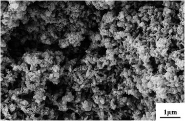 | ||
Fig. 3 SEM images of granular PANI powder morphology. Synthetic conditions: [aniline] = 0.5 M, [aniline]–[APS] = 2![[thin space (1/6-em)]](https://www.rsc.org/images/entities/char_2009.gif) : :![[thin space (1/6-em)]](https://www.rsc.org/images/entities/char_2009.gif) 1, [H3PO4] = 1 M. 1, [H3PO4] = 1 M. | ||
2.2. PANI-based nanofibers
PANI nanofiber composites are one-dimensional objects with a typical diameter of tens of nanometers. There are five basic efficient methods for the preparation of nanofibers:43 (I) rapidly mixed reaction,61 (II) interfacial polymerization,62 (III) dilution technique,63 (IV) seeding method64 and (V) electrospun technique.65 The formation mechanisms of polyaniline nanofibers are quite similar and were fully studied by Huang et al.66 They concluded that the key to synthesizing PANI nanofiber was preventing the secondary growth of the nucleate. It is assumed that under suitable conditions, aniline nucleates are prone to stacking and are stabilized by π–π interactions between phenazine-containing structures, which is shown in Fig. 2. The nucleates induce the formation of nanofibers in their vicinity, and then act as the main part of a nanofiber for continuing growth. In contrast to the formation of granule morphology, homogeneous nucleation of PANI leads to nanofibers, whereas heterogeneous nucleation results in granular particulates. During rapidly mixed reactions, quick consumption of the reactants limits secondary growth, resulting in the nanofiber morphology.40 In interfacial polymerization, PANI nanofibers form at the interface, where aniline reacts with the oxidant. This process also carries the nanofibers away from the reaction interface, which suppresses the secondary growth of irregular particles. New nucleates can stack on different directions of the growing nanofibers, thus extending the one-dimensional structure to a network columnar structure. The adsorption of free nucleates at the nanofibers results in their branching.67 Li et al.68 reported a facile rapid polymerization route to synthesize high quality PANI nanofibers initiated by APS/Fe2+ redox initiator. Different concentrations of HCl play a crucial role in the formation of PANI nanofiber morphology. In addition, the composition of redox initiator and the molar ratio of aniline to redox initiator influences the size and morphology of the polyaniline nanofibers. As shown in Fig. 4, only with concentrations of HCl in a certain range could the author produce PANI nanofibers.68 As the concentration of HCl increased, diameters of polyaniline nanofibers became longer. These nanofibers had a high aspect ratio, whose formation process was free of any templates or surfactants. Because better impact toughness and higher anticorrosion property can be achieved due to higher effective surface areas and shorter penetration depths of target molecules,69 PANI nanofiber composites are widely applied in corrosion protection.70,71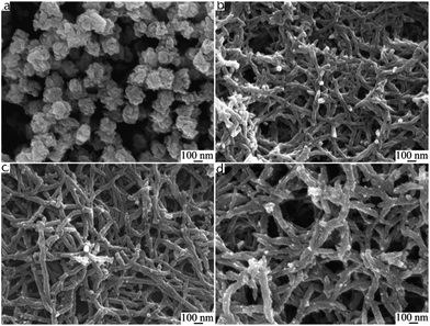 | ||
Fig. 4 SEM images of polyaniline nanofibers synthesized using different concentrations of HCl. (a) 0.01 M; (b) 0.2 M; (c) 0.5 M; (d) 1 M. Synthetic conditions: [aniline] = 0.05 M, [aniline]–[APS] = 4![[thin space (1/6-em)]](https://www.rsc.org/images/entities/char_2009.gif) : :![[thin space (1/6-em)]](https://www.rsc.org/images/entities/char_2009.gif) 1, [APS]–[Fe2+] = 3 1, [APS]–[Fe2+] = 3![[thin space (1/6-em)]](https://www.rsc.org/images/entities/char_2009.gif) : :![[thin space (1/6-em)]](https://www.rsc.org/images/entities/char_2009.gif) 2, and 6 h.68 2, and 6 h.68 | ||
2.3. PANI-based nanotubes
Nanotubes, which have an internal cavity in the middle, are one-dimensional objects such as nanofibers. PANI nanotubes are one of the most interesting objects among nanostructures in the conducting polymer family. PANI nanotubes can be prepared by physical approaches and chemical routes such as soft-template synthesis, hard physical template-guided synthesis and electrospinning synthesis. The formation mechanism of nanotubes around a template is similar to that of nanofibers.34 PANI-based nanotubes are produced growing nucleates under the guidance of templates such as inside membrane pores and on the surface of template structures. Pan et al.72 developed a reactive template method for producing the PANI nanotube. MnO2 was assumed to be the template and oxidant. When the oxidation of aniline occurred on the surface of the manganese oxide template, MnO2 was consumed, leading to a hollow PANI structure (Fig. 5). Various morphologies should be possible by simply changing the shape of MnO2. Mahmoudian et al.73 exhibited the effect of PANI nanotubes and nanofibers in polyvinyl butyral coating on corrosion protective performance of mild steel. It was confirmed that the resistance of the coating containing PANI nanofibers was three times lower than that containing PANI nanotubes after 30 days of immersion. This effect was explained by the lower surface area of the nanofibers compared to nanotubes of the same mass. To produce PANI nanotubes, Deshpande et al.74 used multi-wall carbon nanotubes (MWCNT) as a template and synthesized PANI over this template. It was observed that the corrosion rate of low-carbon steel coated with the composite as an anticorrosive was about 3.6 times lower than that of epoxy painted steel.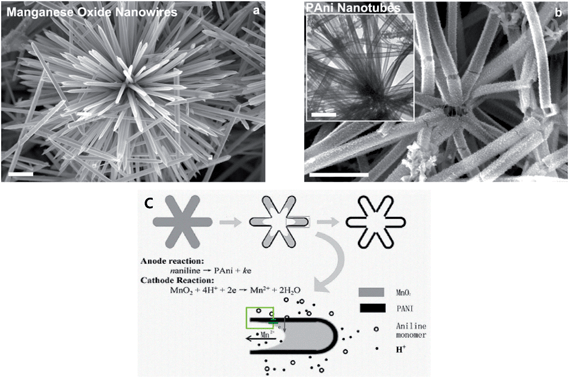 | ||
| Fig. 5 SEM images of (a) cryptomelane-phase manganese oxide template. (b) Resultant polyaniline nanotubes. Inset of (b) is a TEM image of polyaniline nanotubes. (c) Schematic illustration of possible microzone galvanic cell reaction occurring during the conversion from manganese oxide wire to PANI nanotube. The scale bar is 1 μm.72 | ||
2.4. PANI-based nanospheres
PANI nanospheres with a diameter of around 200 nm, whether hollow or not, are expected to be promising candidates in academic applications of anticorrosion.75,76 Soft-template is a typical method to synthesize PANI-based nanospheres. As shown in Fig. 2, micro-emulsion polymerization can be applied to produce nanocapsules and nano-composites. Surfactants are usually used for the formation of micelles; the oxidation of aniline and self-assembly of nucleates occurs inside the micelles to achieve the final nanosphere morphology. In acetone solution, uniform PANI nanospheres were successfully synthesized by using cellulose acetate (CA) as a single template, which provided the first example of uniform PANI nanospheres synthesized in a non-aqueous system.77 Fig. 6 shows the morphology of PANI nanospheres prepared by the oxidation of aniline in phosphoric acid aqueous solution using APS as an oxidant; aniline forms micelles by itself. PANI nanosphere composite has high specific surface when mixed with a resin, and shows better solvation and excellent hydrophobic interaction on the surface. Lv et al.78 successfully synthesized PANI nanocapsules by using the interface of mini-emulsion droplets as a template. A hydrophobic liquid self-healing agent, whose release could be stimulated upon reduction and delayed under oxidation, was encapsulated in the PANI capsules, making them promising candidates for self-healing applications and anticorrosion in metallic systems.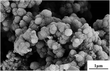 | ||
Fig. 6 SEM images of PANI nanosphere prepared in phosphoric acid. Synthetic conditions: [aniline] = 0.2 M, [aniline]–[APS] = 4![[thin space (1/6-em)]](https://www.rsc.org/images/entities/char_2009.gif) : :![[thin space (1/6-em)]](https://www.rsc.org/images/entities/char_2009.gif) 5, [H3PO4] = 1 M. 5, [H3PO4] = 1 M. | ||
2.5. Other morphologies
Zhu et al.79 synthesized conductive rambutan-like hollow spheres of PANI, which were self-assembled by using perfluorooctane sulfonic acid (PFOSA) as a dopant and a soft template, causing super-hydrophobicity simultaneously. The morphological evolution of PANI helixes80 was achieved by a facile process through the generation of onion-like, multi-lamellar vesicles used as a novel soft template and a liquid crystal acting as a promoter for PANI polymerization and self-assembly, which is a breakthrough in the synthesis of helical structures. Whether solid or hollow, the urchin-like PANI nanoparticles with an average radius of 60–200 nm have been successfully prepared by Prasannan et al.81 and Yang et al.,82 as shown in Fig. 7(a) and (b), respectively. The solid urchin-like PANI nanoparticles were synthesized selectively using β-CD-mediated micro emulsion polymerization in the presence of FeCl3 as a structure-directing agent, while the hollow nanoparticles were successfully synthesized by applying polystyrene spheres as template and support. FeCl3 was also used as a mild oxidant and structure-directing agent. Zhao et al.48 studied the interactions between the aniline oligomer and the molecules of the medium and synthesized three-dimensional assemblies of flower-like and urchin-like microspheres, whose contact angle of the surface was surprisingly high at 153.7°. Peng et al.83 prepared a PANI film with biomimetic superhydrophobic structures using a nanocasting technique. The illustration of Xanthosoma sagittifolium replication is shown in Fig. 2. Polydimethylsiloxane (PDMS) was used as a template to replicate the superhydrophobic surface of leaves to PANI, which produced good morphology and corrosion protected PANI film. All the PANI-based nanostructures mentioned above have high contact angle and exhibit super-hydrophobicity, which always contribute to prominent anticorrosion property.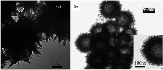 | ||
| Fig. 7 TEM images of urchin-like (a) PANI nanorods prepared through the chemical polymerization of corresponding monomer complex (β-CD and aniline are in equal moles).81 (b) PANI hollow spheres obtained by dispersing hollow spheres preloaded with anilinium salt solution into ferric chloride solution.82 | ||
3. PANI nanostructure-based anticorrosive coatings
Although pure PANI shows good anticorrosion property,84–86 the benefits of the application of PANI are hindered by its poor solubility, infusibility, as well as its almost non-processable properties.87,88 There are two basic methods for producing PANI-containing composites and improving the applications of PANI: (I) mixing PANI composites with matrix polymer by mechanical dispersion;89–91 (II) synthesizing PANI composites in the presence of matrix to improve dispersibility.92 The significance of these processes is their convenient processibility and low price. The advantages and disadvantages of coating systems containing PANI composites and their preparation methods are given in Table 2.| Organic coating system | Composition of corrosion inhibitora [Ref.] | Methods of coating preparation | Advantage | Disadvantage |
|---|---|---|---|---|
| a ND–PANI, nano-diamond–polyaniline; PANI–MWCNT, multi-wall carbon nanotube–polyaniline; PANI/P-PVA, polyaniline/partially phosphorylated poly (vinyl alcohol); PNA, poly(1-naphthylamine); SEPI, superhydrophobic electroactive polyimide; CSA, camphor sulfonic acid; DBSA, dodecylbenzene sulfonic acid; TSA, p-toluene sulfonic acid; PANI(PPA), phenylphosphonate-doped polyaniline; PANI (CSA), camphor sulfonic acid-doped polyaniline; ES, emeraldine salt; EB, emeraldine base. | ||||
| PANI film | ND–PANI6 CNTs–PANI19,69 | Chemical/electrochemical polymerization | Great anticorrosion property | Poor solubility, infusible, non-processable properties |
| Epoxy resin | PANI–lignosulfonate;20 ZnO–PANI;22 PANI–MWCNT;74,91 nano-PANI;88,98 PANI/P-PVA104 | Solution blending matrix polymers and PANI | High resistance to heat, water or chemicals; excellent adhesion to metals; PANI acts as curing agent for epoxy resin | Ease to chalking and yellowing when exposed to ultraviolet radiation |
| Polyurethane | PANI and PNA;105,106 DBSA doped PANI108,110 | Solution blending matrix polymers and PANI; copolymerization of oligoaniline with other monomers | Low color change, high gloss retention and scratch resistance | Poor resistance towards mechanical strains, deformation or degradation at high temperatures |
| Polyimides | SEPI123 | Copolymerization of oligoaniline with other monomers | Striking dielectric, thermal, adhesive, dimensional stability | Poor resistance to alkalis or inorganic acids |
| Alkyd resin | PANI doped with HCl–DBSA–CSA–TSA;87 PANI and PNA;96 PANI–EB/ES117 | Solution blending matrix polymers and PANI | Good adhesion, flexibility, resistance to acid, and durability | Poor resistance to caustic alkali |
| Polyvinyl butyral (PVB) | PANI nanotubes;73 PANI shell with AuNPs75 | Solution blending matrix polymers and PANI | Strong binding, optical clarity, adhesion to many surfaces, toughness and flexibility | Poor resistance to chemical and high temperature |
| Acrylic polymers and copolymers | PANI (PPA) and PANI (CSA)113 | Solution blending matrix polymers and doped PANI counter-ion-induced processibility | Good adhesion, chemical inertness, photo stability, and environmental stability film-forming properties | Limited resistance in water or soil |
| Chlorinated rubber | PANI–ES/EB and DBSA-doped PANI119 | Solution blending matrix polymers and PANI | Excellent resistance to water | Poor solvent resistance and high VOC content |
Since pure PANI is neither soluble nor fusible in water as well as in organic solvents, the soluble and heat-processable polymer materials containing PANI have gradually become one of the important topics in materials science.93,94 In common solvents, the development of better solubility of PANI was first achieved by Cao et al.95 They reported that the counter-ion could induce the processibility of the resulting polyaniline complex by using a suitably functionalized protonated polyaniline. The use of oxide passive film, which is formed by the interaction of polyaniline and steel, implied that pure PANI coating film on the surface of mild steel had a good protective effect but its corrosion protection was short term due to its poor barrier to water.96 To achieve long-term protection of metal, it is necessary to develop a blended coating containing both conventional resin and PANI.
3.1. Polyaniline epoxy resin coatings for corrosion inhibition
Epoxy resin is widely applied in the coating industry because of its superb adhesion to metals and high resistance to heat and corrosive solvent.97Ge et al.98 prepared PANI nanofibers using four kinds of different dopant acids by rapidly mixed reaction. The best morphology with uniform diameter and several microns length was observed, especially in H2SO4. The study also found that the curing time of epoxy resin could be delayed by adding PANI. Morphology and counter-anion would impact the anticorrosion effect of the doped PANI. It was observed that H3PO4-doped PANI showed the best protective effect, followed by H2SO4-doped PANI, and then by HNO3-doped PANI and HCl-doped PANI. In addition to increased corrosion resistance, epoxy–PANI composites improved other unique properties such as thermal, mechanical and conductivity properties.99,100 For example, PANI can act as a curing agent for epoxy resin with covalent bonds formed between the amine groups of PANI and the epoxy groups of epoxy resin; the heat to cure increases as PANI loading increases.101 Electrical conductivity of the epoxy–PANI nano-composites has been achieved by increasing the loading102 or decreasing the size98 of PANI, and the morphology effect was studied by Zhang et al.103 For the conductivity study, at the same loading level, volume resistivity in epoxy nano-composites with PANI nanofibers was lower than that in epoxy nano-composites with PANI nanospheres. The junctions of PANI nanospheres with lower aspect ratio were more than those in the PANI nanofibers with higher aspect ratio. Compared to pure epoxy, the improved dielectric property was attributed to the large interfacial polarization of polymer nano-composites. Chen and Liu104 successfully synthesized conducting polyaniline/partially phosphorylated poly (vinyl alcohol) (PANI/P-PVA) spherical nanoparticles with better dispersion. Variations in the open circuit potential (OCP) values and electrochemical impedance spectroscopy (EIS) spectra with time of exposure demonstrated that waterborne PANI/P-PVA-containing coatings with PANI/P-PVA content of 2.5 wt% were able to offer higher corrosion protection than PANI ES-containing coatings with PANI ES content of 2.5 wt% because of significant dispersibility in aqueous and uniform distribution of the former system. The appearance of three-coated panels after salt spray test for 30 days is shown in Fig. 8, which confirmed that severely bubbled or obvious corrosion was not observed on the 2.5 wt% PANI/P-PVA coating.
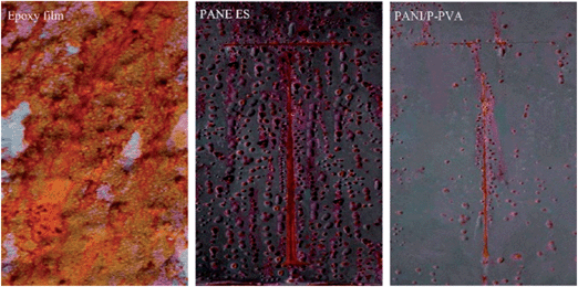 | ||
| Fig. 8 Photograph of pure epoxy-coated panel, 2.5 wt% PANI ES-coated panel, and 2.5 wt% PANI/P-PVA-coated panel after 30 days of exposure to salt spray test.104 | ||
3.2. Polyaniline polyurethane coatings for corrosion inhibition
The advantage of polyurethane coatings is their remarkable resistance to ultraviolet radiation and weather. Compared to epoxy coatings, they are also widely used for corrosion protection,105,106 especially in an environment where sunlight is abundant, because this type of coating exhibits low loss of gloss and color change when exposed to ultraviolet radiation.107 Due to good abrasion resistance, hardness, gloss, general chemical resistance, and impact resistance coupled with zero or low volatile organic compound (VOC) emissions, waterborne polyurethane dispersions are widely investigated. Gurunathan et al.108 for the first time used aqueous cationomeric polyurethane dispersions (PUDs) blending with 2 wt%, 4 wt% and 6 wt% of polyaniline–dodecyl benzene sulfonic acid (DBSA) water dispersions to form new conductive composites. Accelerated corrosion tests revealed that PUD-2000–PANI 6% showed superior corrosion protection on mild steel coupons, which can be observed in Fig. 9. The numbers in the names are different polyols used in the experiment. Moreover, as reported by Chen et al.,109 fibrous structure of DBSA-doped PANI was prepared and well-dispersed in the conducting waterborne polyurethane (WPU) matrix. These blends of conducting films can be used for corrosion protection, for antistatic requirements and in other fields. Different results were found by Diniz et al.,110 who compared organic coatings based on epoxy and polyurethane matrices containing PANI doped with DBSA. PANI had an adverse effect on polyurethane paints by a decrease in resistance, whereas the epoxy-based coatings exhibited improved performance due to different interactions of PANI–DBSA pigments with different matrices.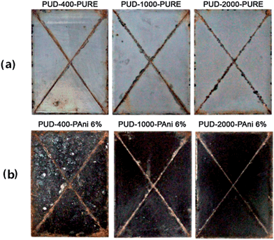 | ||
| Fig. 9 Photographs showing MS panels coated with (a) pure and (b) blended polymers after exposing to salt spray test (300 h).108 | ||
3.3. Polyaniline acrylic polymer coatings for corrosion inhibition
Acrylic polymers and copolymers are widely used in the formulation of protective coatings due to their good adhesion, film-forming properties and photo-stability. Sathiyanarayanan et al.111,112 investigated the comparative anticorrosive performance of coatings containing TiO2, PANI and PANI–TiO2 composites (PTC) on steel in an acrylic binder. The performance of the coatings containing a granule morphology of the above mentioned three samples was evaluated by immersion test in 3% NaCl for 60 days, salt fog test for 35 days and OPC and EIS technique. Results showed that the OPC values of PTC-containing coating were higher than that of the coatings with TiO2 or PANI. PTC coating resistance values were two orders higher than the others. The author considered that the enhanced performance of PTC coatings was due to a uniform distribution of granule PANI instead of bulk PANI, which could form a more uniform passive film to protect the surface. Silva et al.113 investigated the electrochemical behaviors of polymeric blends formed by phenylphosphonate (PPA)-doped PANI and camphorsulphonate (CSA)-doped PANI, both of which were used as corrosion inhibitors for iron in sulphuric acid solutions with or without chloride ions. This study showed that the chemical nature of the dopant acid used for preparing PANI was a crucial choice, which would determine the solubility of PANI and the anticorrosion properties of the coatings. Both the polymeric films acted as smart coatings, releasing anions on demand with different redox behaviors, and CSA-doped PANI exhibited better protective property.3.4. Polyaniline alkyd resin coatings for corrosion inhibition
Alkyd-based coatings are described to exhibit good adhesion, durability, flexibility, and high resistance.114 Oil-based alkyds are one of the most widely used industrial protective coating materials due to their color stability, low cost, and exceptional weatherability in most environmental situations.115 Bhanvase et al.116 dispersed PANI and PANI–CaCO3 nano-composite in alkyd resin in different percentages. The structure and morphology effect of adding PANI and PANI–CaCO3 nano-composite on the anticorrosion and mechanical properties of alkyd resin were discussed. The results showed that PANI–CaCO3 resulted in an enhanced adhesion of alkyd resin to metal substrate, an improvement in the impact strength of composite alkyd coatings, and a decreased corrosion rate of PANI–CaCO3 alkyd resin. These results were attributed to the synergistic effects of PANI and nano-size CaCO3. Marti et al.117 examined the performance of four anticorrosive pigments used in alkyd primer. Very small weight percentages of PANI showed good dispersion in organic solvents such as xylene and organochloride, and provided greater protection to the matrix than other conducting polymers or zinc phosphate. Therefore, it is suggested that PANI is a satisfactory substitute for classical zinc-containing corrosion inhibitors.3.5. Polyaniline used in other coatings and aniline oligomer-derivating polymers for corrosion protection
Yuan et al.118 developed a novel strategy by combining in situ chemical oxidative graft polymerization and surface-initiated ATRP to fabricate antibacterial poly(4-vinylaniline)–polyaniline (PVAn–PANI) bilayer coatings for combating biocorrosion by sulfate-reducing bacteria (SRB) in seawater on stainless steel (SS) substrates. Electrochemical results revealed that PVAn–PANI-modified SS surface conferred corrosion resistance and the desired high barrier ability on SS substrates. With antibacterial properties of quaternized PVAn–PANI bilayers and inherent anticorrosion capability, it was potentially useful for steel-based equipment under harsh marine environments.PANI, as an anticorrosion agent, was also studied in chlorinated rubber (CR)-based coating system.119 Sakhri et al.120 discussed the different protective mechanisms of zinc phosphate and polyaniline as pigments in chlorinated rubber paint. They also found that PANI used as an anticorrosive pigment in chlorinated rubber paint at low loading of 1.5 wt% was more efficient than zinc phosphate.
In addition to applying nanostructure of PANI to improve the corrosion protection of coating, aniline oligomer-derivating electroactive polymers with nanostructure, including electroactive epoxy and electroactive polyimide, have attracted much research attention,121,122 which is a promising area for corrosion protection. For example, Chang et al.123 used nanocasting technique and incorporated the well-defined and conjugated oligoaniline into copolymer backbones to obtain a biomimetic superhydrophobic electroactive polyimide (SEPI) surface structure from a natural Xanthosoma sagittifolium leaf, which combined the beneficial properties of specific oligoaniline with desirable polymer properties such as mechanical strength and film-forming ability. Fig. 10 shows the polymeric surface, and the inset picture exhibits the high contact angle. Tafel and Nyquist plots indicated that SEPI coating offered better protection against corrosion than the common coatings.123
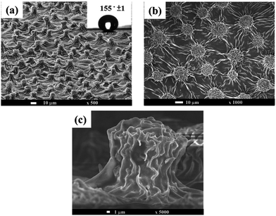 | ||
| Fig. 10 SEM images of (a) Xanthosoma sagittifolium leaf-like superhydrophobic polymeric surface. Inset shows the contact angle of polymeric surface. (b) Top view of polymeric surface. (c) Cross-sectional view of polymeric surface.123 | ||
3.6. Protection process and anticorrosion mechanism of polyaniline-based coating
Anticorrosion mechanisms for PANI-based coatings are considered to be quite complex. The morphology and composition of PANI, type of matrix resin, local pH, humidity, galvanic activity, corrosive environment, and test method affects the rate of corrosion; all of these factors are regarded as important parameters.124,125 Fang et al.126 investigated pure PANI coatings deposited on the metal substrates in different solutions by cyclic voltammetry. They summarized the mechanism in which ES had a positive potential to maintain the substrate in a passivation state, and PANI coating could work as a physical barrier to prevent the diffusion of a corrosive media. Thick, compact and excellent adherence was required for pure PANI coating to provide better protection. However, the exact mechanisms for the corrosion processes of PANI-based coatings, which are more complicated than pure PANI, are yet to be fully elucidated.There are several protective mechanisms of polyaniline material such as passivation mechanism, electric field shielding mechanism, bipolar coating mechanism, adsorption mechanism, anode protection mechanism, and mechanism of dopant ions inhibition. The essence of these mechanisms is the unique oxidation-reduction of polyaniline. These are briefly discussed in the following sections.
Wessling127 considered that the formation of the passive film is due to catalytic oxide-redox reactions. He reported the catalytic passivation mechanism of PANI to iron, as shown in Scheme 3. ES was an intermediate in the oxidation of aniline, and LS was the reduction state of polyaniline. The theory pointed out that the dense oxide film kept the metal the passivating region and decreased the corrosion rate of iron.128,129 In addition, some studies have already confirmed that the oxide film was mainly composed of Fe2O3 in the outer layer and the Fe3O4 layer near the iron surface by XPS130–133 and Raman spectra.134 Moreover, the oxide film was also found in the scratched part or bare metal area, which explained the superior resistance of polyaniline to pitting and scratch. Moraes et al.96 synthesized a PANI film from phosphate buffer solutions on active metals by the electrochemical method. They assumed that a secondary layer formed by insoluble phosphate also played a key role in the high oxidative capacity of the surface.
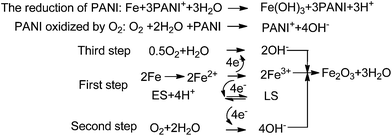 | ||
| Scheme 3 Description of the catalytic passivation of iron by PANI.127 | ||
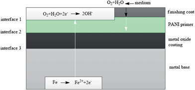 | ||
| Fig. 11 Barrier protection mechanism of PANI.136 | ||
Jain et al.138 presented the mechanism of the electric field effect. The interface between metal and polyaniline yielded an electric field. Electric field and electron transfer were in opposite directions, which could prevent electron transfer from the metal to the oxidant. Conventional organic coating could not form an electric field, which could act as a shield for electron transfer. When the PANI-based coating suffered some defects (scratches or pitting), it still exhibited anticorrosion effects. Radhakrishnan et al.139 intentionally scratched the coating and observed its self-healing property with no rust on the surface even after a long-time exposure to corrosion conditions. They explained these results as the additional cross-linking of PANI. Hence, it is not shielding alone that affects the protection of the metals, and further studies should be conducted to describe this mechanism.
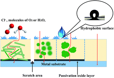
As mentioned above, PANI nanostructure-based organic coatings are expected to substantially develop the resistance of coating against three types of failure situations. As depicted in Fig. 12, the nanostructure of PANI composites can enhance the adhesion and mechanical properties of the coating by increasing the interactions between nanoscale composites and targeted substrates. The pathways for Cl−, H2O and O2 to get to the metal substrate are extended, and thus the ion and gas barrier properties of the coating are improved by PANI nanostructures. Higher specific surface area of nanotubes results in more contact areas between PANI and matrix polymer; therefore, PANI nanotubes exhibit superior protection to the metal among various PANI nanostructures. In addition to hydrophobicity from the coating with rugged appearance, PANI-based coatings can create a passivation oxide layer for the entire surface and protect the scratched area with self-healing attributes.
4. Conclusions and prospects
The oxidation of aniline can produce a variety of nanostructures with different sizes and shapes, including granules, nanofibers, nanotubes and nanospheres. It is concluded that different PANI-based nanostructures can improve the protection of metal by forming passivation oxide and complex layers. By blending with different resin matrices, we could get various anticorrosion mixtures, which could be applied in sundry occasions. The protection processes and anticorrosion mechanisms of PANI-based coatings are complicated due to the wide variations in research processes (PANI-based nanostructure, dispersivity, corrosive environment, doped acid, coating type). PANI nanostructure-based polymer coatings can enhance anticorrosion properties by increasing coating adhesion, producing a high potential of the metal and the self-healing of the engraved area. The significant advantages of nano-PANI anticorrosive coatings lie not only in their easy producing process and eco-friendly, energy-saving and long-term anticorrosion properties, but also in their prospect for preparing self-healing coatings in scratched and pinhole areas, where bare steel surface is exposed to the corrosive ambience. With more comprehension on the extension of the service period of these coatings, remarkable achievements can be made in different industries such as marine, petroleum, construction and energy.Acknowledgements
Financial supports from the Guiding fund of Oceanic Interdisciplinary Research of Zhejiang University (2012HY002B), the Science and Technology Innovation Team of Ningbo (2011B82002), the Natural Science Foundation of Zhejiang Province (Y4110187), and the State Key Laboratory of Chemical Engineering (no. SKL-ChE-12D02) are gratefully acknowledged.References
- L. Hao, S. Zhang, J. Dong and W. Ke, Corros. Sci., 2011, 53, 4187 CrossRef CAS PubMed.
- F. U. Renner, A. Stierle, H. Dosch, D. M. Kolb, T. L. Lee and J. Zegenhagen, Nature, 2006, 439, 707 CrossRef CAS PubMed.
- A. Stierle, Science, 2008, 321, 349 CrossRef CAS PubMed.
- D. G. Shchukin, M. Zheludkevich, K. Yasakau, S. Lamaka, M. G. S. Ferreira and H. Möhwald, Adv. Mater., 2006, 18, 1672 CrossRef CAS.
- A. Kalendová, P. Kalenda and D. Veselý, Prog. Org. Coat., 2006, 57, 1 CrossRef PubMed.
- H. Gomez, M. K. Ram, F. Alvi, E. Stefanakos and A. Kumar, J. Phys. Chem. C, 2010, 114, 18797 CAS.
- N. V. Blinova, J. Stejskal, M. Trchová, J. Prokeš and M. Omastová, Eur. Polym. J., 2007, 43, 2331 CrossRef CAS PubMed.
- M. Yan, C. A. Vetter and V. J. Gelling, Corros. Sci., 2013, 70, 37 CrossRef CAS PubMed.
- V. Annibaldi, A. D. Rooney and C. B. Breslin, Corros. Sci., 2012, 59, 179 CrossRef CAS PubMed.
- N. K. Guimard, N. Gomez and C. E. Schmidt, Prog. Polym. Sci., 2007, 32, 876 CrossRef CAS PubMed.
- S. Palraj, M. Selvaraj, M. Vidhya and G. Rajagopal, Prog. Org. Coat., 2012, 75, 356 CrossRef CAS PubMed.
- Y. Zhu, J. Zhang, Y. Zheng, Z. Huang, L. Feng and L. Jiang, Adv. Funct. Mater., 2006, 16, 568 CrossRef CAS.
- K. Lee, S. Cho, S. Heum Park, A. J. Heeger, C. Lee and S. Lee, Nature, 2006, 441, 65 CrossRef CAS PubMed.
- X. Guo, J. P. Small, J. E. Klare, Y. Wang, M. S. Purewal, I. W. Tam, B. H. Hong, R. Caldwell, L. Huang, S. O'Brien, J. Yan, R. Breslow, S. J. Wind, J. Hone, P. Kim and C. Nuckolls, Science, 2006, 311, 356 CrossRef CAS PubMed.
- G. Wu, K. L. More, C. M. Johnston and P. Zelenay, Science, 2011, 332, 443 CrossRef CAS PubMed.
- W. Hung, C. Hung, Y. Chang, J. Dai, Y. Li, H. He, S. Chen, T. Huang, Y. Wei, X. Jia and J. Yeh, J. Mater. Chem., 2011, 21, 4581 RSC.
- T. Huang, Y. Su, T. Yeh, H. Huang, C. Wu, K. Huang, Y. Chou, J. Yeh and Y. Wei, Electrochim. Acta, 2011, 56, 6142 CrossRef CAS PubMed.
- T. Wang and Y. Tan, Corros. Sci., 2006, 48, 2274 CrossRef CAS PubMed.
- A. A. Hermas, M. Abdel Salam and S. S. Al-Juaid, Prog. Org. Coat., 2013, 76, 1810 CrossRef CAS PubMed.
- G. Gupta, N. Birbilis, A. B. Cook and A. S. Khanna, Corros. Sci., 2013, 67, 256 CrossRef CAS PubMed.
- Y. Li, H. Zhang, X. Wang, J. Li and F. Wang, Corros. Sci., 2011, 53, 4044 CrossRef CAS PubMed.
- A. Mostafaei and F. Nasirpouri, Prog. Org. Coat., 2014, 77, 146 CrossRef CAS PubMed.
- V. K. Thakur, G. Ding, J. Ma, P. S. Lee and X. Lu, Adv. Mater., 2012, 24, 4071 CrossRef CAS PubMed.
- W. Jia, L. Su and Y. Lei, Biosens. Bioelectron., 2011, 30, 158 CrossRef CAS PubMed.
- T. G. Kim, H. Shin and D. W. Lim, Adv. Funct. Mater., 2012, 22, 2446 CrossRef CAS.
- F. Cheng, J. Liang, Z. Tao and J. Chen, Adv. Mater., 2011, 23, 1695 CrossRef CAS PubMed.
- X. Han, C. Chang, L. Yuan, T. Sun and J. Sun, Adv. Mater., 2007, 19, 1616 CrossRef CAS.
- Y. Cao, L. Xiao, M. L. Sushko, W. Wang, B. Schwenzer, J. Xiao, Z. Nie, L. V. Saraf, Z. Yang and J. Liu, Nano Lett., 2012, 12, 3783 CrossRef CAS PubMed.
- L. Yuan, X. Xiao, T. Ding, J. Zhong, X. Zhang, Y. Shen, B. Hu, Y. Huang, J. Zhou and Z. L. Wang, Angew. Chem., Int. Ed., 2012, 51, 4934 CrossRef CAS PubMed.
- J. Han, L. Li, P. Fang and R. Guo, J. Phys. Chem. C, 2012, 116, 15900 CAS.
- C. Chang, C. Weng, C. Chien, T. Chuang, T. Lee, J. Yeh and Y. Wei, J. Mater. Chem. A, 2013, 1, 14719 CAS.
- D. Li, J. Huang and R. B. Kaner, Acc. Chem. Res., 2008, 42, 135 CrossRef PubMed.
- S. Bhadra, D. Khastgir, N. K. Singha and J. H. Lee, Prog. Polym. Sci., 2009, 34, 783 CrossRef CAS PubMed.
- Y. Long, M. Li, C. Gu, M. Wan, J. Duvail, Z. Liu and Z. Fan, Prog. Polym. Sci., 2011, 36, 1415 CrossRef CAS PubMed.
- A. Pud, N. Ogurtsov, A. Korzhenko and G. Shapoval, Prog. Polym. Sci., 2003, 28, 1701 CrossRef CAS PubMed.
- H. Wang, L. Wang, R. Wang and X. Tian, J. Mater. Sci., 2011, 46, 1049 CrossRef CAS.
- D. S. Sutar, S. S. Major, R. S. Srinivasa and J. V. Yakhmi, Thin Solid Films, 2011, 520, 351 CrossRef CAS PubMed.
- F. I. El-Dib, W. M. Sayed, S. M. Ahmed and M. Elkodary, J. Appl. Polym. Sci., 2012, 124, 3200 CrossRef CAS.
- S. Chaudhari and P. P. Patil, Electrochim. Acta, 2011, 56, 3049 CrossRef CAS PubMed.
- J. Huang and R. B. Kaner, Chem. Commun., 2006, 0, 367 RSC.
- H. D. Tran, J. M. D'Arcy, Y. Wang, P. J. Beltramo, V. A. Strong and R. B. Kaner, J. Mater. Chem., 2011, 21, 3534 RSC.
- J. Stejskal, I. Sapurina and M. Trchová, Prog. Polym. Sci., 2010, 35, 1420 CrossRef CAS PubMed.
- H. D. Tran, D. Li and R. B. Kaner, Adv. Mater., 2009, 21, 1487 CrossRef CAS.
- N. A. Ogurtsov, Y. V. Noskov, K. Y. Fatyeyeva, V. G. Ilyin, G. V. Dudarenko and A. A. Pud, J. Phys. Chem. B, 2013, 117, 5306 CrossRef CAS PubMed.
- H. Qiu, J. Zhai, S. Li, L. Jiang and M. Wan, Adv. Funct. Mater., 2003, 13, 925 CrossRef CAS.
- F. Lux, Polymer, 1994, 35, 2915 CrossRef CAS.
- I. Sapurina and J. Stejskal, Polym. Int., 2008, 57, 1295 CrossRef CAS.
- Y. Zhao, J. Stejskal and J. Wang, Nanoscale, 2013, 5, 2620 RSC.
- W. Huang, B. D. Humphrey and A. G. MacDiarmid, J. Chem. Soc., Faraday Trans. 1, 1986, 82, 2385 RSC.
- F. Wudl, R. O. Angus, F. L. Lu, P. M. Allemand, D. Vachon, M. Nowak, Z. X. Liu, H. Schaffer and A. J. Heeger, J. Am. Chem. Soc., 1987, 109, 3677 CrossRef CAS.
- K. M. Molapo, P. M. Ndangili, R. F. Ajayi, G. Mbambisa, S. M. Mailu, N. Njomo, M. Masikini, P. Baker and E. I. Iwuoha, Int. J. Electrochem. Sci., 2012, 7, 11859 CAS.
- M. Liu, X. Mao, H. Zhu, A. Lin and D. Wang, Corros. Sci., 2013, 75, 106 CrossRef CAS PubMed.
- L. Pan, H. Qiu, C. Dou, Y. Li, L. Pu, J. Xu and Y. Shi, Int. J. Mol. Sci., 2010, 11, 2636 CrossRef CAS PubMed.
- Y. Wang, H. D. Tran, L. Liao, X. Duan and R. B. Kaner, J. Am. Chem. Soc., 2010, 132, 10365 CrossRef CAS PubMed.
- S. Sathiyanarayanan, V. Karpakam, K. Kamaraj, S. Muthukrishnan and G. Venkatachari, Surf. Coat. Technol., 2010, 204, 1426 CrossRef CAS PubMed.
- Y. Liao, V. Strong, W. Chian, X. Wang, X. Li and R. B. Kaner, Macromolecules, 2012, 45, 1570 CrossRef CAS.
- S. Virji, J. Huang, R. B. Kaner and B. H. Weiller, Nano Lett., 2004, 4, 491 CrossRef CAS.
- J. Stejskal, I. Sapurina, M. Trchová and E. N. Konyushenko, Macromolecules, 2008, 41, 3530 CrossRef CAS.
- T. Pan and Z. Wang, Microsc. Res. Tech., 2013, 76, 1186 CrossRef CAS PubMed.
- D. Chen, Y. Miao and T. Liu, ACS Appl. Mater. Interfaces, 2013, 5, 1206 CAS.
- L. A. McCullough, B. Dufour and K. Matyjaszewski, Macromolecules, 2009, 42, 8129 CrossRef CAS.
- J. Chen, D. Chao, X. Lu and W. Zhang, Mater. Lett., 2007, 61, 1419 CrossRef CAS PubMed.
- M. Zhao, X. Wu and C. Cai, J. Phys. Chem. C, 2009, 113, 4987 CAS.
- S. Xing, C. Zhao, S. Jing and Z. Wang, Polymer, 2006, 47, 2305 CrossRef CAS PubMed.
- C. Weng, Y. Jhuo, C. Chang, C. Feng, C. Peng, C. Dai, J. Yeh and Y. Wei, Soft Matter, 2011, 7, 10313 RSC.
- J. Huang and R. B. Kaner, Angew. Chem., Int. Ed., 2004, 43, 5817 CrossRef CAS PubMed.
- C. F. Zhou, X. S. Du, Z. Liu, S. P. Ringer and Y. W. Mai, Synth. Met., 2009, 159, 1302 CrossRef CAS PubMed.
- G. Li, C. Zhang, Y. Li, H. Peng and K. Chen, Polymer, 2010, 51, 1934 CrossRef CAS PubMed.
- X. Yang, B. Li, H. Wang and B. Hou, Prog. Org. Coat., 2010, 69, 267 CrossRef CAS PubMed.
- S. Ma, G. Song, N. Feng and P. Zhao, J. Appl. Polym. Sci., 2012, 125, 1601 CrossRef CAS.
- H. Zhang, J. Wang, X. Liu, Z. Wang and S. Wang, Ind. Eng. Chem. Res., 2013, 52, 10172 CrossRef CAS.
- L. J. Pan, L. Pu, Y. Shi, S. Y. Song, Z. Xu, R. Zhang and Y. D. Zheng, Adv. Mater., 2007, 19, 461 CrossRef CAS.
- M. R. Mahmoudian, Y. Alias and W. J. Basirun, Prog. Org. Coat., 2012, 75, 301 CrossRef CAS PubMed.
- P. Deshpande, S. Vathare, S. Vagge, E. Tomšík and J. Stejskal, Chem. Pap., 2013, 67, 1072 CrossRef CAS.
- A. Vimalanandan, L. Lv, T. H. Tran, K. Landfester, D. Crespy and M. Rohwerder, Adv. Mater., 2013, 25, 6980 CrossRef CAS PubMed.
- C. Weng, Y. Chen, Y. Jhuo, L. Yi-Li and J. Yeh, Polym. Int., 2013, 62, 774 CrossRef CAS.
- L. Zhang, H. Ma, F. Cao, J. Gong and Z. Su, J. Polym. Sci., Part A: Polym. Chem., 2012, 50, 912 CrossRef CAS.
- L. Lv, Y. Zhao, N. Vilbrandt, M. Gallei, A. Vimalanandan, M. Rohwerder, K. Landfester and D. Crespy, J. Am. Chem. Soc., 2013, 135, 14198 CrossRef CAS PubMed.
- Y. Zhu, D. Hu, M. X. Wan, L. Jiang and Y. Wei, Adv. Mater., 2007, 19, 2092 CrossRef CAS.
- C. Li, J. Yan, X. Hu, T. Liu, C. Sun, S. Xiao, J. Yuan, P. Chen and S. Zhou, Chem. Commun., 2013, 49, 1100 RSC.
- A. Prasannan, T. L. B. Truong, P. Hong, N. Somanathan, I. Shown and T. Imae, Langmuir, 2010, 27, 766 CrossRef PubMed.
- M. Yang, X. Yao, G. Wang and H. Ding, Colloids Surf., A, 2008, 324, 113 CrossRef CAS PubMed.
- C. Peng, K. Chang, C. Weng, M. Lai, C. Hsu, S. Hsu, Y. Hsu, W. Hung, Y. Wei and J. Yeh, Electrochim. Acta, 2013, 95, 192 CrossRef CAS PubMed.
- A. Olad and R. Nosrati, Prog. Org. Coat., 2013, 76, 113 CrossRef CAS PubMed.
- E. Akbarinezhad, M. Ebrahimi, F. Sharif, M. M. Attar and H. R. Faridi, Prog. Org. Coat., 2011, 70, 39 CrossRef CAS PubMed.
- M. Kraljić, Z. Mandić and L. Duić, Corros. Sci., 2003, 45, 181 CrossRef.
- G. S. Goncalves, A. F. Baldissera Jr, L. F. Rodrigues, E. M. A. Martini and C. A. Ferreira, Synth. Met., 2011, 161, 313 CrossRef CAS PubMed.
- M. R. Bagherzadeh, F. Mahdavi, M. Ghasemi, H. Shariatpanahi and H. R. Faridi, Prog. Org. Coat., 2010, 68, 319 CrossRef CAS PubMed.
- H. Gu, S. Tadakamalla, Y. Huang, H. A. Colorado, Z. Luo, N. Haldolaarachchige, D. P. Young, S. Wei and Z. Guo, ACS Appl. Mater. Interfaces, 2012, 4, 5613 CAS.
- U. Riaz, S. Ahmad and S. M. Ashraf, Mater. Corros., 2009, 60, 280 CrossRef CAS.
- J. Xu, P. Yao, Z. Jiang, H. Liu, X. Li, L. Liu, M. Li and Y. Zheng, J. Appl. Polym. Sci., 2012, 125, E334 CrossRef CAS.
- M. Mumtaz, C. Labrugère, E. Cloutet and H. Cramail, Langmuir, 2009, 25, 13569 CrossRef CAS PubMed.
- A. Rahy, T. Rguig, S. J. Cho, C. E. Bunker and D. J. Yang, Synth. Met., 2011, 161, 280 CrossRef CAS PubMed.
- Y. W. Lin and T. M. Wu, J. Appl. Polym. Sci., 2012, 1262, E123 CrossRef.
- Y. Cao and P. Smith, Polymer, 1993, 34, 3139 CrossRef CAS.
- S. R. Moraes, D. Huerta-Vilca and A. J. Motheo, Prog. Org. Coat., 2003, 48, 28 CrossRef CAS.
- M. Ochi, K. Takemiya, O. Kiyohara and T. Nakanishi, Polymer, 1998, 39, 725 CrossRef CAS.
- C. Y. Ge, X. G. Yang and B. R. Hou, J. Coat. Technol. Res., 2012, 1, 59 CrossRef.
- R. S. Jadhav, K. J. Patil, D. G. Hundiwale and P. P. Mahulikar, Polym. Adv. Technol., 2011, 22, 1620 CrossRef CAS.
- B. Belaabed, J. L. Wojkiewicz, S. Lamouri, N. El Kamchi and N. Redon, Polym. Adv. Technol., 2012, 23, 1194 CrossRef CAS.
- J. Jang, J. Bae and K. Lee, Polymer, 2005, 46, 3677 CrossRef CAS PubMed.
- C. Liu, S. Lee, C. Ho, J. Han and K. Hsieh, J. Phys. Chem. C, 2008, 112, 15956 CAS.
- X. Zhang, Q. He, H. Gu, H. A. Colorado, S. Wei and Z. Guo, ACS Appl. Mater. Interfaces, 2012, 5, 898 Search PubMed.
- F. Chen and P. Liu, ACS Appl. Mater. Interfaces, 2011, 3, 2694 CAS.
- U. Riaz, S. M. Ashraf and S. Ahmad, Anti-Corros. Methods Mater., 2008, 55, 308 CrossRef CAS.
- S. M. Ashraf, S. Ahmad and U. Riaz, Polym. Int., 2007, 56, 1173 CrossRef CAS.
- G. A. Howarth, Surf. Coat. Int., Part B, 2003, 86, 111 CrossRef CAS.
- T. Gurunathan, C. R. K. Rao, R. Narayan and K. V. S. N. Raju, Prog. Org. Coat., 2013, 76, 639 CrossRef CAS PubMed.
- C. Chen, Y. Kan, C. Mao, W. Liao and C. Hsieh, Surf. Coat. Technol., 2013, 231, 71 CrossRef CAS PubMed.
- F. B. Diniz, G. F. De Andrade, C. R. Martins and W. M. De Azevedo, Prog. Org. Coat., 2013, 76, 912 CrossRef CAS PubMed.
- S. Sathiyanarayanan, S. Syed Azim and G. Venkatachari, Electrochim. Acta, 2007, 52, 2068 CrossRef CAS PubMed.
- S. Sathiyanarayanan, S. Syed Azim and G. Venkatachari, Synth. Met., 2007, 157, 205 CrossRef CAS PubMed.
- J. E. Pereira Da Silva, S. I. Córdoba De Torresi and R. M. Torresi, Corros. Sci., 2005, 47, 811 CrossRef CAS PubMed.
- P. A. Sørensen, S. Kiil, K. Dam-Johansen and C. E. Weinell, J. Coat. Technol. Res., 2009, 6, 135 CrossRef.
- J. Alam, U. Riaz and S. Ahmad, Curr. Appl. Phys., 2009, 9, 80 CrossRef PubMed.
- B. A. Bhanvase and S. H. Sonawane, Chem. Eng. J., 2010, 156, 177 CrossRef CAS PubMed.
- M. Marti, G. Fabregat, D. S. Azambuja, C. Aleman and E. Armelin, Prog. Org. Coat., 2012, 73, 321 CrossRef CAS PubMed.
- S. Yuan, S. Tang, L. Lv, B. Liang, C. Choong and S. O. Pehkonen, Ind. Eng. Chem. Res., 2012, 51, 14738 CrossRef CAS.
- A. F. Baldissera, D. B. Freitas and C. A. Ferreira, Mater. Corros., 2010, 61, 790 CrossRef CAS.
- A. Sakhri, F. X. Perrin, E. Aragon, S. Lamouric and A. Benaboura, Corros. Sci., 2010, 52, 901 CrossRef CAS PubMed.
- C. Weng, C. Chang, C. Peng, S. Chen, J. Yeh, C. Hsu and Y. Wei, Chem. Mater., 2011, 23, 2075 CrossRef CAS.
- T. Yang, C. Peng, Y. L. Lin, C. Weng, G. Edgington, A. Mylonakis, T. Huang, C. Hsu, J. Yeh and Y. Wei, J. Mater. Chem., 2012, 22, 15845 RSC.
- K. Chang, H. Lu, C. Peng, M. Lai, S. Hsu, M. Hsu, Y. Tsai, C. Chang, W. Hung, Y. Wei and J. Yeh, ACS Appl. Mater. Interfaces, 2013, 5, 1460 CAS.
- A. J. Dominis, G. M. Spinks and G. G. Wallace, Prog. Org. Coat., 2003, 48, 43 CrossRef CAS.
- G. Spinks, A. Dominis, G. Wallace and D. Tallman, J. Solid State Electrochem., 2002, 6, 85 CrossRef CAS.
- J. Fang, K. Xu, L. Zhu, Z. Zhou and H. Tang, Corros. Sci., 2007, 49, 4232 CrossRef CAS PubMed.
- B. Wessling, Synth. Met., 1997, 85, 1313 CrossRef CAS.
- B. Wessling, Adv. Mater., 1994, 6, 226 CrossRef CAS.
- B. Wessling and J. Posdorfer, Electrochim. Acta, 1999, 44, 2139 CrossRef CAS.
- M. Fahlman, S. Jasty and A. J. Epstein, Synth. Met., 1997, 85, 1323 CrossRef CAS.
- W. Lu, R. L. Elsenbaumer and B. Wessling, Synth. Met., 1995, 71, 2163 CrossRef CAS.
- T. Yeh, T. Huang, H. Huang, Y. Huang, Y. Cai, S. Lin, Y. Wei and J. Yeh, Polym. Chem., 2012, 3, 2209 RSC.
- Y. Hao, F. Liu and E. Han, Prog. Org. Coat., 2013, 76, 571 CrossRef CAS PubMed.
- G. S. Gonçalves, A. F. Baldissera, L. F. Rodrigues Jr, E. M. A. Martini and C. A. Ferreira, Synth. Met., 2011, 161, 313 CrossRef PubMed.
- F. Beck, V. Haase and M. Schrötz, AIP Conf. Proc., 1996, 354, 115 CrossRef CAS PubMed.
- T. Schauer, A. Joos, L. Dulog and C. D. Eisenbach, Prog. Org. Coat., 1998, 33, 20 CrossRef CAS.
- W. P. Hou, Y. Liu, Z. Y. Ge and W. Y. Zhao, Mater. Corros., 2013, 64, 960 CrossRef CAS.
- F. C. Jain, J. J. Rosato, K. S. Kalonia and V. S. Agarwala, Corrosion, 1986, 42, 700 CrossRef CAS.
- S. Radhakrishnan, N. Sonawane and C. R. Siju, Prog. Org. Coat., 2009, 64, 383 CrossRef CAS PubMed.
- Y. M. Abu and K. Aoki, J. Electroanal. Chem., 2005, 583, 133 CrossRef CAS PubMed.
- K. Kamaraj, S. Sathiyanarayanan, S. Muthukrishnan and G. Venkatachari, Prog. Org. Coat., 2009, 64, 460 CrossRef CAS PubMed.
- K. Kamaraj, T. Siva, S. Sathiyanarayanan, S. Muthukrishnan and G. Venkatachari, J. Solid State Electrochem., 2012, 16, 465 CrossRef CAS PubMed.
- S. de Souza, J. E. Pereira Da Silva, S. I. Córdoba De Torresi, M. L. A. Temperini and R. M. Torresi, Electrochem. Solid-State Lett., 2001, 4, B27 CrossRef CAS PubMed.
- S. Sathiyanarayanan, S. K. Dhawan, D. C. Trivedi and K. Balakrishnan, Corros. Sci., 1992, 33, 1831 CrossRef CAS.
- V. Brusic, M. Angelopoulos and T. Graham, J. Electrochem. Soc., 1997, 144, 436 CrossRef PubMed.
- A. T. Özyılmaz, Prog. Org. Coat., 2005, 54, 127 CrossRef PubMed.
- R. Hasanov and S. Bilgiç, Prog. Org. Coat., 2009, 64, 435 CrossRef CAS PubMed.
- E. Hür, G. Bereket and Y. Şahin, Prog. Org. Coat., 2006, 57, 149 CrossRef PubMed.
| This journal is © The Royal Society of Chemistry 2014 |

