 Open Access Article
Creative Commons Attribution 3.0 Unported Licence
Recent progress in metal–organic complexes for optoelectronic applications
Hui
Xu
*ab,
Runfeng
Chen
bc,
Qiang
Sun
b,
Wenyong
Lai
c,
Qianqian
Su
b,
Wei
Huang
*cd and
Xiaogang
Liu
*be
aKey Laboratory of Functional Inorganic Material Chemistry, Ministry of Education and School of Chemistry and Materials, Heilongjiang University, 74 XueFu Road, Harbin 150080, China. E-mail: hxu@hlju.edu.cn
bDepartment of Chemistry, Faculty of Science, National University of Singapore, 3 Science Drive 3, Singapore 117543, Singapore. E-mail: chmlx@nus.edu.sg
cKey Laboratory for Organic Electronics & Information Displays, Institute of Advanced Materials, Nanjing University of Posts & Telecommunications, Nanjing 210023, China
dSingapore-Jiangsu Joint Research Center for Organic/Bio-electronics and Information Displays and Institute of Advanced Materials, Nanjing University of Technology, Nanjing 211816, China. E-mail: wei-huang@njtech.edu.cn
eInstitute of Materials Research and Engineering, Agency for Science, Technology and Research, 3 Research Link, Singapore 117602, Singapore
First published on 17th February 2014
Abstract
The design and characterization of metal–organic complexes for optoelectronic applications is an active area of research. The metal–organic complex offers unique optical and electronic properties arising from the interplay between the inorganic metal and the organic ligand. The ability to modify chemical structure through control over metal–ligand interaction on a molecular level could directly impact the properties of the complex. When deposited in thin film form, this class of materials enable the fabrication of a wide variety of low-cost electronic and optoelectronic devices. These include light emitting diodes, solar cells, photodetectors, field-effect transistors as well as chemical and biological sensors. Here we present an overview of recent development in metal–organic complexes with controlled molecular structures and tunable properties. Advances in extending the control of molecular structures to solid materials for energy conversion and information technology applications will be highlighted.
1. Introduction
Metal–organic complexes, combining facile synthesis with tunable optical properties, have attracted much interest over the past decades owing to their enormous potential application in optoelectronic devices. For example, with the right set of optoelectronic properties, metal–organic complexes may point the way for the next generation of solar energy conversion, replacing fragile, high-temperature processing semiconductor materials with durable, low-cost printed plastic electronics.Fig. 1 shows important milestones in the development of metal–organic complexes for optoelectronic applications. Discovery of the first organic semiconductor copper phthalocyanine (CuPc) can be dated back to 1948.1 In the late 1980s, Tang and Van Slyke at Kodak fabricated the first thin film light-emitting diode using tris(8-quinolinolato) aluminum(III) (Alq3) as the emitting layer.2 Research into organic light-emitting diodes culminated in 1998 with the work of Forrest and co-workers, who reported the discovery of organic light-emitting devices (OLEDs) employing phosphorescent metal–organic complexes.3 These pioneering studies have truly revolutionized our understanding of the correlation between the chemical structure and optical properties of the complexes and also led to remarkable progress in developing efficient optoelectronic devices at a moderate price.
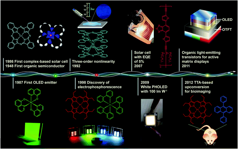 | ||
| Fig. 1 Milestones in the development of optoelectronic complexes. Eley firstly demonstrated semiconducting behavior of CuPc complexes in 1948.1 The p-type CuPc was utilized by Tang to fabricate the first organic p–n junction solar cell with an efficiency of 1% in 1986.4 In the following year, Tang and Van Slyke demonstrated the first OLED with practical luminance using another complex emitter Alq3.2 In 1992, a three-order nonlinear optical property was observed for phthalocyanine complex ScPc2.5 Baldo et al. in 1998 reported electrophosphorescence phenomenon using a red phosphorescent complex dye 2,3,7,8,12,13,17,18-octaethyl-21H,23H-porphine platinum(II) (PtOEP) as emitter.3 In 2007, Wong et al. further improved the efficiency of complex-based solar cells to a record of 5% with a Pt(II) coordination polymer.6 In 2009, with light out-coupling technology, Reineke et al. achieved a maximum power efficiency of 100 lm W−1 in phosphorescent OLEDs, which was comparable to that obtained from fluorescent tubes.7 In 2011, McCarthy et al. demonstrated low-voltage driving active-matrix display pixels by integrating OLED cells into OTFT.8 In 2012, the upconversion-emission nanoparticle containing triplet–triplet annihilation system was firstly applied in bio-imaging by Liu et al.9 | ||
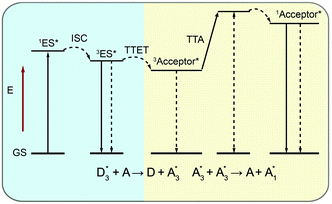
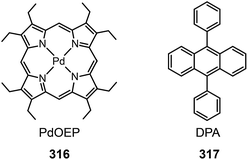
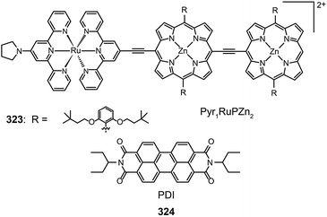
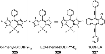
This review article provides an update on recent advances in the development and implementation of metal–organic complexes for optoelectronic applications. We begin by describing the basic properties of the metal ion and organic molecule, which have a strong influence on the performance of an optoelectronic device. Next, a brief overview of typical luminescence processes occurring in organic molecules or metal–organic complexes will be presented, followed by thorough coverage of the latest research on OLEDs involving metal–organic complexes. The emphasis will be placed on the illustration of different types of fluorescent and phosphorescent emitters, and on the discussion of recent efforts in device configurations for high-efficiency OLEDs. The application of metal complex-based donors in organic photovoltaics will be covered in a subsequent chapter. The last chapter of this review highlights the emerging field of triplet–triplet annihilation upconversion through use of metal–organic complexes. A major goal of this review is to provide illustrative accounts on recent work and systematize our knowledge of the subject, extracting fundamental principles from diverse research topics.
2. Basic properties of metal–organic complexes
2.1 Metal ions
A key to the design of high performance metal–organic-based optoelectronic devices is the understanding of the pivotal role of metal ions involved in controlling the optoelectronic properties of metal–organic complexes.2.2 Photoresponsive organic molecules
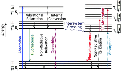
Owing to the weak electronic delocalization, photoresponsive organic materials have two distinctive features as compared to their inorganic counterparts. One is the existence of well-defined spin (singlet and triplet) states in isolated molecules. The luminescence processes in organic materials are typically associated with the excited states of molecules, while the luminescence spectra in inorganic materials are attributed to either defects or impurities in the host lattice or to the excited states of the isolated atom or ion. A second important difference arises from the fact that the size of excitations (Frenkel excitons) tends to be small in organic molecular crystals, dominated by the strong coulomb interaction between an electron and a hole. Thus, the molecular excitons with a considerable amount of binding energy (0.1–1 eV) can be located on one molecule.The emphasis on the optoelectronic process can vary depending on specific applications. For organic photovoltaics, more attention is paid to the excitation process of organic molecules. The absorption spectra, corresponding to the excitation process, of the organic molecules should match well with incident solar energy to render high conversion efficiency. For light-emitting applications, the center of attention is given to the luminescence process which can be quantified by quantum efficiency. To achieve a high quantum efficiency, one has to boost the probability of radiative transition and suppress the energy loss transitions via vibrational relaxation or internal conversion. The relative photoluminescence quantum yield (Φ) of organic compounds in dilute solutions can be measured using conventional dyes as references according to the equation shown below:
 | (1) |
 | (2) |
 | (3) |
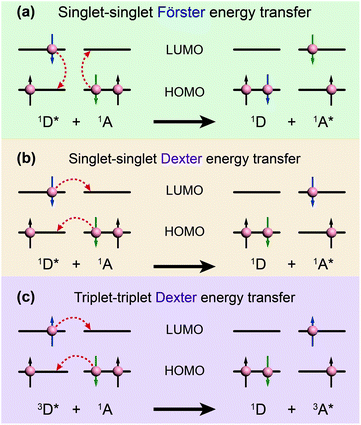 | ||
| Fig. 3 Schematic diagrams of (a) Förster energy transfer and (b, c) Dexter energy transfer. D and A denote donor and acceptor, respectively. | ||
In contrast, Dexter energy transfer can travel only short distances (<1 nm) for both singlet and triplet excited states as the exchange interactions are dictated by the wavefunction overlap of electron clouds.11 The rate constant of Dexter energy transfer is given by eqn (4):
 | (4) |
The degree of spectral overlap between donor emission spectrum and acceptor absorption spectrum is clearly the dominant factor in determining the efficiency of energy transfer. To increase the probability of energy transfer, the excited energy gap between the donor and the acceptor generally needs to be controlled within the range of 2000–4000 cm−1. Fortunately, a wealth of synthetic strategies and technologies for chemical synthesis allow for facile tailoring of the band gap and energy levels of organic molecules owing to their structure-dependent electronic properties.
3. Metal–organic complexes for OLEDs
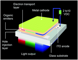
An OLED is a thin, glowing component made of layers of organic semiconducting materials. A typical multilayer design is shown in Fig. 4. When a voltage is applied between two electrodes, the cathode pumps electrons into the dye-containing emission layer located between the two electrodes while the anode supplies electron holes. These holes can jump to the emission layer to form bound electron–hole pairs, namely the so-called excitons. The return of the excitons to the ground state, i.e. the recombination of holes and electrons, leads to a relaxation of the energy levels of the electrons in the form of light. The design of sandwiched layers facilitates charge injection and enhances the recombination rate of electrons and holes.Presently, the power efficiency of three-color OLEDs, given in lumen per watt (lm W−1), can reach up to 100 lm W−1 for green,12 30 lm W−1 for red,13 and 40 lm W−1 for blue.14 Similar to fluorescent tubes, white-emitting OLEDs can show remarkable efficiencies up to 100 lm W−1 through external out-coupling technologies that reduce light diffusion and scattering.7 To suppress the concentration quenching effect of the emitters and improve device efficiency, the emission layer is often prepared by blending guest emitters into host matrices. The choice of the emitters is of paramount importance in the device design as they affect recombination and radiative probability, and consequently determine the device performance, including IV characteristics, brightness and power efficiency. On the basis of different excited states, the emitters can be classified into two categories: fluorescent and phosphorescent metal–organic complexes.
3.1 Electrofluorescent complexes
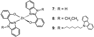
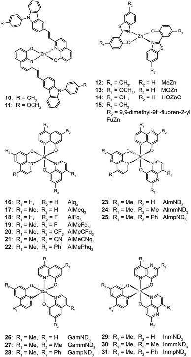
The ability of fluorescent complexes with different peripheral substituents to alter the emission profile of OLEDs is at the heart of their role as light-emitting centers. Since the pioneering work of Tang and Van Slyke on Alq3,2 significant progress has been made in developing highly efficient emitters or electron-transport materials containing Zn(II), Mg(II), Be(II), Al(III), and In(III) complexes.15A subsequent study by Xu et al. reported the synthesis of blue-emitting Zn(II) complexes (7–9) using a phenylbenzoimidazole ligand.15c The authors found that the presence of a pendant N-hexylcarbazole group endows the complex 9 with a deep blue emission at 422 nm and a high quantum yield of 64%. Additionally, the carbazole substituent provides improved color purity and enhanced thermal stability with a decomposition temperature (Td) of greater than 400 °C. This improvement is attributed to the largely elevated HOMO level (∼0.6 eV) of the complex due to the existence of the peripheral carbazole moiety. These authors fabricated non-doped multilayer devices using the compound 9 and demonstrated much improved electroluminescence performance with a turn-on voltage of 4.5 V, a luminance of 2648 cd m−2 and a maximum current efficiency of 0.54 cd A−1. A parallel development by the group of Li also reported the effects of the carbazole functional group on the emission and electrical properties of the Zn(II) complexes (10 and 11).15d
In 2009, Roh et al. investigated several green-emitting Zn(II) complexes (12–15) with benzothiazole and its derivatives to produce white-light emission.15e Interestingly, the substitution of an electron-donating methoxyl group in the Zn(II)-chelated complex 13 triggered a large red shift in emission from 495 (λmax) to 524 nm in organic solvents. The incorporation of a highly conjugated fluorenyl group in 15 induced a further bathochromic shift of the fluorescence emission. The authors argued that the large Stokes shift is due to the intramolecular proton transfer at the excited state. In multilayer electroluminescent devices, these authors reported a high luminance (1 cd m−2 at 3.5 V, 10![[thin space (1/6-em)]](https://www.rsc.org/images/entities/char_2009.gif) 400 cd m−2 at 14 V) for the fluorenyl-substituted Zn(II) complex 15. This group also examined the electron transport property of the complexes and their suitability as electron-transporting layer materials as a replacement of widely used Alq3.
400 cd m−2 at 14 V) for the fluorenyl-substituted Zn(II) complex 15. This group also examined the electron transport property of the complexes and their suitability as electron-transporting layer materials as a replacement of widely used Alq3.
![[thin space (1/6-em)]](https://www.rsc.org/images/entities/char_2009.gif) 040 cd m−2. Measured maximum external quantum and current efficiencies for the devices were 4.0% and 10.4 cd A−1, respectively.
040 cd m−2. Measured maximum external quantum and current efficiencies for the devices were 4.0% and 10.4 cd A−1, respectively.
Liao et al. synthesized a series of group III (Al, Ga, and In) metal chelates (23–31) with hydroxynaphthyridine derivatives as chelating ligands.16 These metal chelates exhibit deep blue emissions at 425–447 nm, wide band gaps and high thermal stability. The authors argued that the addition of an electron-donating group at the para-position of the pyridine ring promotes LUMO energy levels. Aluminium chelates 23–25 exhibited good fluorescence quantum yields around 45–47% in dichloromethane solution. Among the metal chelates, AlmmND324 has been shown to be the most efficient non-doped blue emitter with a maximum emission at 432 nm (Fig. 5). For AlmmND3-based OLEDs, these authors achieved a high current efficiency of 2.00 cd A−1 and an external quantum efficiency of 3.79%.
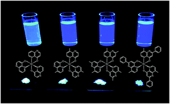 | ||
| Fig. 5 Emission images of AlND3, AlmND323, AlmmND324, and AlmpND325 recorded in solution and solid state under irradiation by UV light. (Reproduced with permission from ref. 16. Copyright 2009, American Chemical Society.) | ||
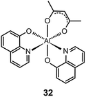
It should be noted that most research activities have been focused on Al(III) complexes with three ligands symmetrically arranged around the metal center. This arrangement offers high thermal stability and low probability of exciton quenching. However, a recent study by Xu et al. on a mixed-ligand complex of Al(III) (Alq2A; 32) has revealed that an asymmetrical arrangement of ligands may offer improved electron-transport mobilities and high electroluminescence efficiency.17 In contrast to OLEDs containing Alq3 complex 16, the devices utilizing complex 32 offer a larger luminance (15![[thin space (1/6-em)]](https://www.rsc.org/images/entities/char_2009.gif) 650 cd m−2 at 12 V) and a higher power efficiency (3.03 lm W−1). For performance improvement it is essential that the mixed ligands impart high electron mobility and show no interference of electron affinity. Another important contributing factor for high device efficiency is that the molecular structure of Alq2A allows the facile formation of a uniform and smooth film. The physical properties and electroluminescence performance of representative fluorescent complexes is summarized in Table 1.
650 cd m−2 at 12 V) and a higher power efficiency (3.03 lm W−1). For performance improvement it is essential that the mixed ligands impart high electron mobility and show no interference of electron affinity. Another important contributing factor for high device efficiency is that the molecular structure of Alq2A allows the facile formation of a uniform and smooth film. The physical properties and electroluminescence performance of representative fluorescent complexes is summarized in Table 1.
| Emitter | Photophysical properties | HOMO/LUMOb (eV) | Device performance | Ref. | |||||
|---|---|---|---|---|---|---|---|---|---|
| Emission peaka (nm) | Φ (%) | Device structurec | Emission peak (nm) | Voltage (V)d | Max. brightness (cd m−2) | Max. efficiencye | |||
| a Measured in solution. b Measured according to the analysis of cyclic voltammetric data and optical energy gaps. c See the Abbreviations section for full names. d Turn-on voltage. e In the order of current efficiency (cd A−1), power efficiency (lm W−1) and external quantum efficiency (%). | |||||||||
| 3 | 428, 463 | 8 | −5.78/−2.45 | ITO/NPB/3/BCP/Alq3/LiF/Al | 430 | — | 1720 | 0.3, —, — | 15b |
| 9 | 422, 422 | — | −5.74/−2.49 | ITO/NPB/9/BCP/Alq3/LiF/Al | 452 | 4.5 | 2648 | 0.54, —, 0.4 | 15c |
| 12 | —, 505 | — | −5.33/−2.67 | ITO/2-TNATA/NPB/12/Alq3/LiF/Al | 495 | <4.2 | ∼4000 | 1.84, 0.91 | 15e |
| 13 | —, 532 | — | −5.31/−2.77 | ITO/2-TNATA/NPB/13/Alq3/LiF/Al | 524 | <4.8 | ∼2000 | 2.10, 0.91 | 15e |
| 15 | —, 532 | — | −5.81/−3.20 | ITO/2-TNATA/NPB/15/Alq3/LiF/Al | 513, 551 | <3.5 | ∼10![[thin space (1/6-em)]](https://www.rsc.org/images/entities/char_2009.gif) 000 000 |
1.90, 1.17 | 15e |
| 16 | 526, 508 | 15 | −5.62/−2.43 | PEDOT:PSS/NPD/16/CsF/Al | — | 5.5 | 52![[thin space (1/6-em)]](https://www.rsc.org/images/entities/char_2009.gif) 300 300 |
4.6, —, 1.4 | 15f |
| 17 | 501, 489 | 38 | −5.53/−2.32 | PEDOT:PSS/NPD/17/CsF/Al | — | 3.5 | 15![[thin space (1/6-em)]](https://www.rsc.org/images/entities/char_2009.gif) 300 300 |
5.2, —, 1.9 | 15f |
| 18 | 499, 484 | 35 | −5.82/−2.60 | PEDOT:PSS/MoO3/TPD/TCTA/18/TPBI/Yb/Ag | — | 4.0 | 8570 | 0.6, —, 0.2 | 15f |
| 19 | 478, 482 | 57 | −5.81/−2.44 | PEDOT:PSS/MoO3/TPD/TCTA/19/Yb/Ag | — | 3.5 | 31![[thin space (1/6-em)]](https://www.rsc.org/images/entities/char_2009.gif) 040 040 |
10.4, —, 4.0 | 15f |
| 20 | 482, 462 | 46 | −5.78/−2.39 | PEDOT:PSS/MoO3/TPD/TCTA/20/TPBI/Yb/Ag | — | 4.2 | 16![[thin space (1/6-em)]](https://www.rsc.org/images/entities/char_2009.gif) 800 800 |
10.1, —, 4.1 | 15f |
| 23 | 415, 431 | 45 | −6.4/−3.0 | ITO/NPB/CBP/23/Bebq2/LiF/Al | 458 | — | 7140 | 1.8, 1.0, 1.8 | 16 |
| 24 | 416, 419 | 45 | — | ITO/NPB/CBP/24/Alq3/LiF/Al | 432 | — | 4444 | 2.0, 0.9, 3.8 | 16 |
| 32 | — | — | −6.49/−3.63 | ITO/2-TNATA/NPB/32/LiF/Al | 513 | — | 15![[thin space (1/6-em)]](https://www.rsc.org/images/entities/char_2009.gif) 650 650 |
4.35, 3.03, — | 17 |
3.2 Electrophosphorescent complexes
The mechanism of phosphorescence involves intersystem crossing characterized by the nonradiative conversion of the initial excited state into another excited state of different multiplicity. The second state acts as an energy reservoir. Radiative decay back to the ground state can occur slowly if spin–orbital coupling causes a breakdown of the spin selection rule. As a result, the excited state of a phosphorescent complex may survive for microseconds or even longer. Theoretically, the internal quantum efficiency of phosphorescent OLEDs can approach 100% because of the contributions from both singlet and triplet excitons. Several excellent reviews on electrophosphorescent complexes and devices have appeared during the past few years.18 Herein, we highlight recent advances in the development of high-performance OLEDs by means of phosphorescent complexes for multicolor displays and white light generation over a wide range of wavelengths.3.2.1.1 Blue-emitting Ir(III) complexes. An important example of phosphorescence is provided by blue-emitting Ir(III) complexes. These blue emitters are important for white light generation. One approach is to mix the blue phosphors with red and green phosphors, each exhibiting a relatively narrow emission spectrum, to create a spectral power distribution that appears white. Alternatively, the white light can be generated by the use of phosphors together with a blue emitter. When a yellow phosphor material is illuminated by the blue emitter, it renders yellow light having a fairly broad spectrum. The remaining blue light, when mixed with the yellow light, results in white light. However, it has been challenging to prepare blue phosphors with a high level of monochromaticity and photostability. For example, iridium(III) bis[(4,6-difluorophenyl)pyridinato-N,C2′] picolinate (FIrpic), one of the most popular blue phosphors, emits at 475 nm with high electrophosphorescence, but is prone to quenching at high concentration and under large current density.19
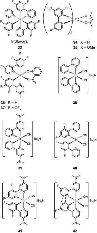
The main approaches for achieving efficient blue phosphorescence include (i) increasing the energy gap by elevating LUMO level or lowering HOMO level; (ii) introducing ancillary ligands with strong field effects;20 and (iii) shortening the effective conjugation length of molecules. For instance, Lee et al.21 recently demonstrated a large reduction (0.33 eV) in the HOMO energy level of a phosphorescent Ir(III) complex (33) bearing fluorine-substituted bipyridine (dfpypy) through functional group modulation. The authors found that this complex exhibits intense blue emission at 438 nm with high color purity (CIE: x = 0.14, y = 0.12) and a higher photoluminescence quantum efficiency than that of FIrpic. The enhanced luminescence was thought to be due to improved metal–ligand charge-transfer. Density functional theory calculations of the complex lent support to this hypothesis.
Lee and Kim demonstrated that the LUMO energy level of a phenylpyridine-based Ir(III) complex (34) can be destabilized by the addition of a methoxy group to the ligand.22 The authors reported that the substitution of the electron-donating group in complex (35) results in a blue shift in emission. In a parallel investigation, Seo et al. reported a new series of highly efficient deep-blue phosphorescent Ir(III) complexes (36 and 37) bearing phenylpyridine-based ligands.23 The authors found that the attachment of a trifluoromethyl (CF3) group to the phenylpyridine ligand induces a bright blue emission at 454 nm due to stabilization of the HOMO level. The multilayer OLEDs based on complex 37 achieved a similar level of performance to that of FIrpic-based devices.
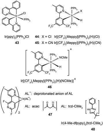
Ancillary ligands can interact strongly with metal ions, and the phosphorescent properties of the complex stem in large part from this interaction. Ancillary ligands with strong ligand field often induce hypochromatic shifts when they are present in a complex. This effect has been systematically investigated by Di Censo et al. using a series of cyano-stabilized Ir(III) complexes (38–42).24 Replacement of one phenylpyridine ligand with two cyano groups leads to a blue shift (10 nm) in the emission spectrum of the resulting complex 38.24 In a separate study, the optical properties of complex (43) containing triphenylphosphine ligands was analyzed.25 This complex was found to exhibit a similar hypochromatic shift to that observed for cyano-stabilized complex 38. The spin-coated polymer light-emitting diodes comprising 43 revealed a moderate power efficiency of 0.86 lm W−1 and an external quantum efficiency of 4.0%. The research groups of Kim26 and Ha27 have pursued the development of blue-emitting phosphorescent Ir(III) complexes (44–48) by appending triphenylphosphine or triazolylpyridine as the ancillary ligand to the metal center.
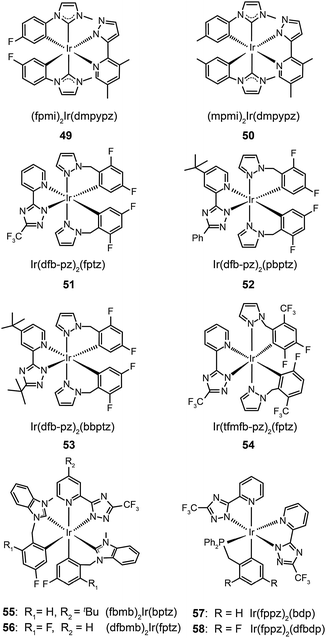
The use of N-heterocyclic carbene ancillary ligands, equipped with very high triplet energy levels,28 allows for facile construction of blue-emitting Ir(III) complexes.29 For example, Chen and co-workers prepared (fpmi)2Ir(dmpypz) (49) and (mpmi)2Ir(dmpypz) (50) that emit pure blue emissions at 455 and 466 nm, respectively.30 The multilayer devices based on 49 and 50 as the dopant emitter showed high external quantum efficiencies of 17.1% and 15.4% with commission internationale de l'éclairage (CIE) coordinates of (0.13, 0.16) and (0.13 and 0.18), respectively.
Complexes 51–54, developed by Wu and co-workers,31 contain nonconjugated N-benzylpyrazole ligands featuring a methylene spacer. This design feature allowed the synthesis of blue phosphorescent complexes with large energy gaps. The methylene spacer serves to effectively interrupt the π conjugation on reacting with a third chelating chromophore. The resulting complexes 51–54 have true blue emissions at 437, 464, 456 and 434 nm, respectively. It was suggested that conjugated ligands not only reduce energy gaps, but also partially offset the modification of HOMO and LUMO levels. However, the electroluminescence performance of these complexes was not satisfactory. Wu and co-workers32 later developed chelating benzyl carbene ligands to alleviate much of this problem. The resulting two phosphors of (fbmb)2Ir(bptz) (55) and (dfbmb)2Ir(fptz) (56) showed bright blue emissions at 460 and 458 nm with photoluminescence quantum yields of 22% and 73%, respectively. They successfully fabricated vacuum-deposited, 56-doped OLEDs, achieving pure blue emission with CIE coordinates of (0.16, 0.13). The electroluminescence efficiencies were also improved with a current efficiency of 6.3 cd A−1, a power efficiency of 4.0 lm W−1, and an external quantum efficiency of up to 6.0% photons per electron.
Replacing carbenes with high-field-strength chelating phosphine ligands in nonconjugated systems can further tune the emission color to the blue end. Chou and co-workers33 have reported a breakthrough in the rational design of novel Ir(fppz)2(bdp) (57) and Ir(fppz)2(dfbdp) (58) phosphors, enabling the corresponding OLEDs to exhibit a true blue CIE chromaticity of (0.15, 0.11) and an external quantum efficiency of 12%. Concurrent increases in the current efficiency (∼11 cd A−1) and power efficiency (∼8 lm W−1) were observed, making these phosphors attractive for use in all phosphorescent displays and illumination devices.
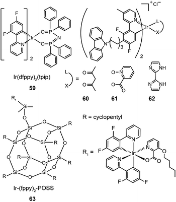
In 2011, Zhu et al. published results on OLEDs containing phosphine oxide ligands.34 The substitution of picolinate with phosphine oxide in FIrpic forms the blue-green emitting Ir(dfppy)2(tpip) (59). Although this does not present a significant improvement with respect to color saturation, the phosphorescent lifetime of 59 is reduced to 0.77 μs, indicating a short-lived excited state in favor of suppressed triplet–triplet annihilation (TTA). In addition to its carrier transport ability, the ancillary phosphine oxide group provides the metal complex with a LUMO level of −2.87 eV suitable for efficient electron injection. Accordingly, an OLED device prepared with 59 showed a current efficiency of 25.5 cd A−1, a power efficiency of 23.5 lm W−1, and a 6.58% efficiency roll-off from 100 to 1000 cd m−2. A paper from Seo et al. shows that the luminescence performance of blue-emitting Ir(III) complexes may be achieved using hole-transporting carbazole moieties.35 The incorporation of peripheral carbazole groups into complexes (60–62) can provide added intramolecular energy transfer to the metal core and facilitate hole injection and transportation. These complexes emit blue-green light with emission peaks located at about 480 nm and CIE coordinates of (0.21, 0.55). Devices doped with these complexes achieved a maximum current efficiency of 20.75 cd A−1, a maximum power efficiency of 5.83 lm W−1, and a peak external quantum efficiency of 7.16%.
The quenching effect caused by intermolecular interaction is perhaps one of the most serious problems for light-emitting phosphors. Although doping in active host matrices can mitigate the issues of TTA and concentration quenching to certain extent, it is generally believed that the potential phase separation may lead to device degradation and decreased performance over time. An intriguing solution is to covalently link the Ir(III) complex to the host matrix. Yang et al.36 reported the use of polyhedral oligomeric silsesquioxane (POSS) in the preparation of monochromatic- and white-emitting devices. Notably, the blue-emitting OLEDs with POSS-modified Ir(III) complex (63) showed a brightness of 1000 cd m−2 and peak external quantum efficiencies in the range of 5–9% with a voltage potential less than 10 V. Despite synthetic challenges, the prospects of using POSS materials are exciting for the development of solution-processable electrophosphorescent devices.
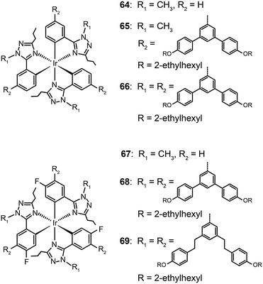
Concentration quenching can be avoided using dendrimers having highly branched molecular structures. An important property of dendrimers is the presence of dynamic internal cavities where luminescent ions or complexes can be comfortably embedded, resulting in a more protected metal center. In 2008, Lo et al. studied the effects caused on the luminescence properties of blue-emitting phenyltriazole Ir(III) complexes (64–66) by substitution of oligophenyl dendron units.37 They showed that the dendron-modified molecules can host the metal in the interior site to suppress the quenching effect. For example, doubly dendronized complex (66) exhibited a blue emission at ∼475 nm and a film photoluminescence quantum yield of 67%. It is particularly worth mentioning that the oligophenyl dendrons do not affect the electronic properties of the complexes. The spin-coated nondoped double-layer devices composed of 66 achieved a luminance of 142 cd m−2 at 3.8 V with an external quantum efficiency of 7.9%. One year later, the same group designed blue phosphorescent dendrimers (67–70) modified with both fluorine and methyl groups.38 The involvement of fluorine atoms enables the emission tuning to a deep blue end, while the methyl group provides steric hindrance to mitigate the quenching effect induced by the fluorine atom. The doubly dendronized complex 70 showed good optical performance, with a high solution photoluminescence quantum yield of 94%, which is more than three times higher than was achievable by the parent complex core. The optimized double-layer devices showed deep blue emission with CIE coordinates of (0.16, 0.16) (Fig. 6).
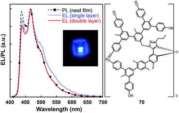 | ||
| Fig. 6 Photoluminescence (PL) and electroluminescence (EL) spectra of 70 (inset: the corresponding digital image of the device derived from 70). (Reproduced with permission from ref. 38. Copyright 2009, American Chemical Society.) | ||
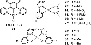
3.2.1.2 Blue-emitting Pt(II) and Ce(III) complexes. Platinum(II) complexes, characterized by a large variety of emissive excited states, are an important class of phosphorescent materials as dopants for fabricating blue-emitting OLEDs. However, when compared to Ir(III) complexes, Pt(II) complexes are much less explored as electrophosphorescent blue emitters for OLED applications. Yang et al. developed a blue-emitting Pt(II) complex (71) based on a fluorinated tridentate pyridine ligand.39 This cyclometallated complex exhibited a narrow emission at 470 nm (λmax) and a photoluminescence efficiency of 46%. To boost the color saturation, the authors utilized high-field-strength carbene moieties, combined with an ancillary ligand of acac, to tune the emission of Pt(II) complexes (72–77) to the spectrally pure blue region.40 Complex 77 exhibited high optical performance, achieving a photoluminescence efficiency of 92%. The optimized devices employing 77 with a doping concentration of 12% showed a peak external quantum efficiency of 6.2%. Recently, the Che group has carried out considerable work on bis(carbene)-based Pt(II) complexes (78–81) featuring highly efficient deep blue emission (Fig. 7).41 The OLED device doped with 80 achieved CIE coordinates of (0.16, 0.16) at 11 V and a maximum luminance of 1200 cd m−2 at a driving voltage of 15 V.
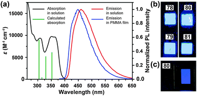 | ||
| Fig. 7 (a) Absorption and photoluminescence spectra of 78 and 79. (b) Photographs showing electroluminescent devices derived from 78–81 under UV irradiation. (c) Photograph showing electroluminescence emission of the device based on 80. (Reproduced with permission from ref. 41. Copyright 2011, Royal Society of Chemistry.) | ||
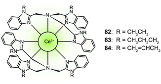
Trivalent lanthanide complexes can also be designed as blue-emitting phosphors in OLED applications. Zheng et al. reported the luminescent cerium(III) complexes (82–84) with the metal ion encapsulated in the cavity formed by two face-to-face arranged tripodal ligands.42 These complexes emitted blue light at ∼440 nm. Complex 83 showed a high photoluminescence efficiency of 55%. The devices based on dopant emitter 83 achieved a current efficiency of 1.5 cd A−1 and a power efficiency of 0.52 lm W−1 with CIE coordinates of (0.18, 0.21). The authors argued that the blue emission is attributed to both metal-based 5d → 4f transition and the ligand sensitization. The ligand serves as a light-harvesting antenna that subsequently transfers the absorbed energy to the Ce(III) ion.
It is important to note that the development of phosphors for optoelectronics has been dominated by Ir(III) complexes since the discovery of electrophosphorescence. The main difference between Ir(III) and Pt(II) complexes is their different coordination modes. Compared with four-coordinated Pt(II) complexes, highly dimensional Ir(III) complexes with six-coordination mode are superior in controlling intermolecular interactions to suppress the quenching effects and in enhancing molecular rigidity to reduce vibronic progressions. In this regard, the Ir(III) complexes seem to be ideal as blue emitters. Furthermore, the yield of Pt(II) complexes containing ligands with strong coordination field is relatively low (<20%). To date, the highest external quantum efficiency realized by blue Pt(II) complexes is 15%, only half of that achieved by blue Ir(III) complexes.43a,b Nevertheless, the simpler coordination mode of Pt(II) complexes can benefit material synthesis and configuration design.
Phosphorescent emissions from Ir(III) and Pt(II) complexes are mainly contributed by 3MLCT and 3ILCT states. Therefore, the emission properties of these materials are significantly dictated by their ligands. Different from Ir(III) and Pt(II) analogues, the blue emission by Ce(III) complexes originates from 4f → 5dj (j = 1–4) transitions of the Ce(III) ion. Strongly emissive Ce(III) complexes require efficient energy transfer and high recombination rates from the ligands under an electrical field. Owing to the relatively high excited state energy of Ce(III) ions, it is difficult to construct suitable ligands as sensitizers, which limits the development of highly efficient electroluminescent Ce(III) complexes.
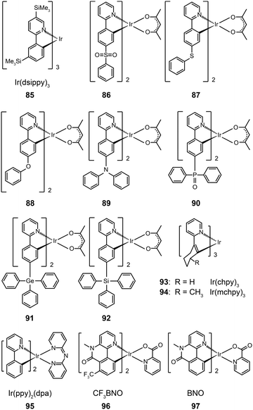
3.2.2.1 Small molecule-based green-emitting Ir(III) complexes. The effect of ligand substitution has been thought to be the primary factor for modulating the emission property of metal complexes. Ir(dsippy)3 (85) demonstrates that the attachment of a trimethylsilyl group can induce significant steric hindrance.46 Importantly, the substitution of this bulky ligand results in improved photostability of the complex and a relatively narrow emission peak. Compared with the device doped with Ir(ppy)3, the device comprising Ir(dsippy)3 enables a lower driving voltage and more stable power efficiency. To assess the influence of electron-donating and electron-withdrawing groups on the emission properties of metal complexes, Zhou et al. systematically investigated a series of Ir(III)-based complexes (86–92).47 All of these complexes exhibit high thermal and morphological stability with a Td value of greater than 350 °C. The authors suggested that the substituents have strong effects on the charge distribution within the molecular orbitals in that the electron-donating group can increase the HOMO energy, while the electron-withdrawing group has the opposite directing effect. As a result, the emissions of these complexes can be tuned from 505 to 550 nm. As the inductive effect of the sulfonyl and phosphine oxide groups can simultaneously reduce the LUMO energy, the authors observed remarkable red-shifts in the emissions of complexes 86 and 90. The devices using these Ir(III)-based complexes have shown moderate electroluminescence performance, of which the complex 88 showcases a current efficiency of 35.02 cd A−1, a power efficiency of 26.82 lm W−1, and an external quantum efficiency of 11.05%.
The use of cycloalkenyl (chpy or mchpy) group instead of the phenyl in Ir(ppy)3 also can lead to increased steric hindrance.48 The corresponding complexes, Ir(chpy)3 (93) and Ir(mchpy)3 (94), emit green yellowish color with the peaks centered around 530 nm. Their HOMO and LUMO energies were modified to −5.0 and −2.5 eV, matching the energy levels of carrier transporting layers. In 2011, Rai et al. reported an interesting dipyridylamido-supported cyclometalated Ir(III) complex, Ir(ppy)2(dpa) (95), which emits green electroluminescence with high current efficiency (123.5 cd A−1) and power efficiency (43.2 lm W−1) (Fig. 8).49 Owing to increased charge transfer between the ligand and the metal, the lifetime of the complex was reduced to 0.17 μs. The authors observed a high photoluminescence quantum yield (87%) of complex 95 in a chloroform solution, which was believed to be due to minimized phosphorescence self-quenching by suppression of triplet–triplet annihilation. High-molecular-weight Ir(III) complexes (96 and 97) also can display relatively short excited-state lifetimes (0.30 and 0.32 μs, respectively) with improved phosphorescence quantum yields.50 Notably, 96 and 97 are solution processible. The phosphorescent organic light-emitting diode (PHOLED) obtained from the spin-coated complex 96 emits blue-green color with a high current efficiency of 89.1 cd A−1 (69.8 lm W−1) at 100 cd m−2.
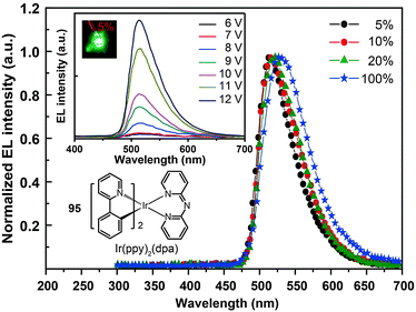 | ||
| Fig. 8 Electroluminescence spectra of PHOLEDs doped with 95 at different concentrations. (Reproduced with permission from ref. 49. Copyright 2011, Royal Society of Chemistry.) | ||
Recently, the non-doped, solution-processed phosphorescent devices containing small-sized molecular phosphors have attracted considerable research interest because of their potential for facile, large-scale fabrication. Ir(III)-based complex (98) features a sterically hindered chelating amidinate ligand which has proven to be effective in solving the self-quenching problem (Fig. 9).51 Weak intermolecular interaction of the complex and its short lifetime of 0.34 μs are believed to be the two main factors. The contribution of the amidinate ligand to the HOMO also improves the hole-injection ability of the complex. The non-doped device of 98 showed rather low driving voltages of 2.40 V for the onset voltage, 3.15 V at 100 cd m−2, and 4.30 V at 1000 cd m−2. The dramatically reduced self-quenching was further confirmed by high power efficiency (32.5 lm W−1), in combination with the excellent stability of the device (28 and 22 lm W−1 at 100 and 1000 cd m−2, respectively).
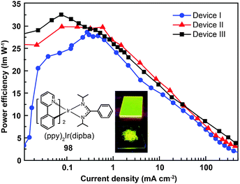 | ||
| Fig. 9 Power efficiency vs. current density curves of PHOLEDs using 98 as phosphor (inset: photographs showing phosphorescent emission of 98 in its film and powder states). (Reproduced with permission from ref. 51. Copyright 2009, Royal Society of Chemistry.) | ||
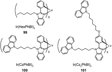
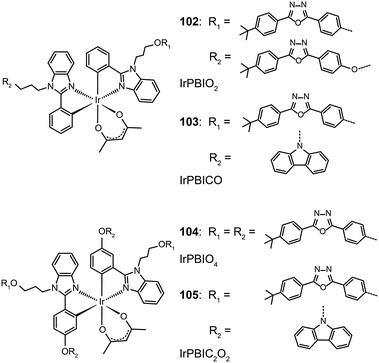
Xu et al. utilized a combined modification of charge-transfer moieties and aliphatic chains to construct solution-processible phosphors (99–101).52 The peripheral carbazolyl groups can facilitate the hole carrier injection and transport while the long hexyl chain improves the solubility of the complexes in common solvents. Furthermore, the surrounding rigid carbazolyl moieties are able to encapsulate the emitting metal center, protecting the latter from self-quenching. This design improved the phosphorescence quantum yield of the six-armed Ir(Cz2PhBI)3101 to ∼70% without significantly altering its characteristic properties. A low turn-on voltage of 2.5 V and a high external quantum efficiency of 5.9% at 100 cd m−2 were achieved for the non-doped devices derived from complex 101. However, the unbalanced carrier currents arising from asymmetric injection and transport characteristics of the carbazole groups allow rapid recombination of hole–electron pairs at the electrode, resulting in luminescence quenching. To balance the carrier injection and transport in metal complexes, the same group further prepared a series of Ir(III) complexes (102–105) having electron-transporting functional groups.53 The space-filling model shows that substituted oxadiazole ligands at multiple positions in complex 105 are effective in segregating the metal centers. As anticipated, the authors observed a high photoluminescence performance with a balanced carrier injecting/transporting ability for complex 105 (Fig. 10). Its non-doped spin-coated devices achieved a current efficiency of 15.41 cd A−1 and a power efficiency of 8.08 lm W−1.
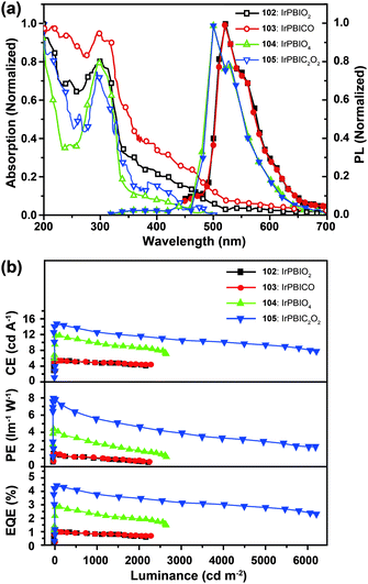 | ||
| Fig. 10 (a) Absorption and photoluminescence spectra of 102–105 dissolved in dilute CH2Cl2 solution. (b) The corresponding efficiency curves of the PHOLEDs derived from 102–105. (Reproduced with permission from ref. 53. Copyright 2011, Royal Society of Chemistry.) | ||
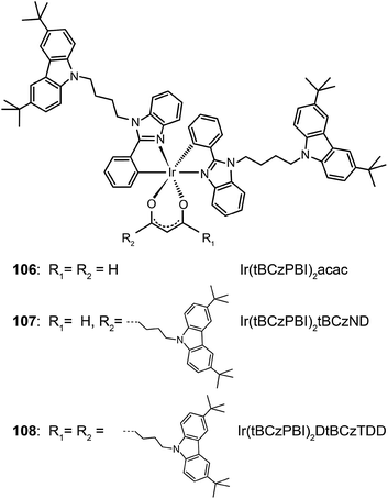
Recently, Chen et al. reported a similar study by employing Ir(III) complexes (106–108) comprising substituted oxadiazole ligands.54 Through device optimization, complex 108 with four extended arms was used to realize a current efficiency of 23.4 cd A−1 and a power efficiency of 16.3 lm W−1. These reports clearly demonstrate that the charge-transfer approach and the aliphatic chain strategy provide largely complementary benefits, which can be combined to construct high performance solution-processible phosphors with reduced quenching effects.
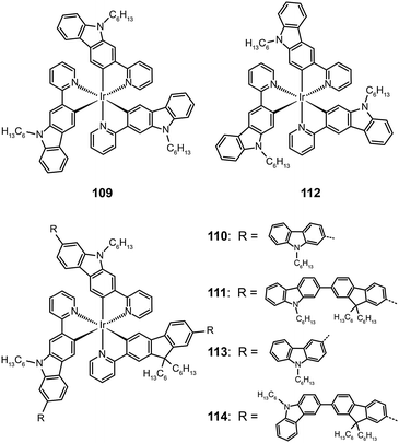
The attachment of oligomeric ligands to a metal ion often markedly influences the optical properties of the metal center. The Ir(III) complexes based on 2-carbazolylpyridine (109–111) or 3-carbazolylpyridine (112–114) have different emissions at 500 and 590 nm, respectively, which can be attributed to their difference in the length of π conjugation.55 However, this difference is readily eliminated by introducing an oligofluorene linker between the carbazolyl and pyridine. The emission of both types of Ir(III) oligomers shifts to 550 nm with increasing numbers of the fluorenyl unit.
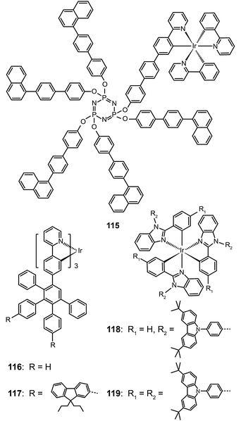
Bolink et al. in 2008 attached the Ir(ppy)3 emitting unit to a solution processable dendrimer based on cyclic phosphazene to form complex 115.56 The cyclic phosphazene is an inert core used to link the dendronic groups for enhanced thermal and morphological stability. This dendrimer complex reveals optical properties similar to Ir(ppy)3, but its emission peak shifts to 550 nm due to the extended conjugation by the diphenyl linker. The corresponding spin-coated devices derived from complex 115 can be turned on at 3 V, with a maximum current efficiency of 24.0 cd A−1, a power efficiency of 16.7 lm W−1, and an external quantum efficiency of 7.0%. The current efficiency versus luminance curves were rather flat as evident by the essentially unaltered current efficiency (19.4 cd A−1) at maximum brightness (3362 cd m−2). The authors ascribed this to the occurrence of balanced carrier injection and transport in emitting layers.
As the green-emitting dendrimers have been extensively studied, the research focus has recently shifted to developing effective strategies for dendronization. Many functional groups have shown strong effects on the optoelectronic performance of the dendrimers. As shown in Ir(III) complexes (116 and 117), the modification of the dendrons with functional groups further decreases the intermolecular interaction between the emitting cores, thereby resulting in improved luminescence performance.57 On the other hand, increasing the density of substitution can boost the electroluminescence efficiency of the dendrons. Comparable electroluminescence performance for Ir(III) complexes with low density of high-generation dendrons can be achieved with high density of low-generation dendrons. Representative examples are Ir(III) complexes (118 and 119), which can be relatively easily synthesized.58 Complex 119 with six carbazole groups endowed its nondoped spin-coated devices with a high current efficiency of 45.7 cd A−1 (with an external quantum efficiency of 13.4%), which is higher than that achieved with a similar Ir(III) complex modified with three second-generation dendrons (34.7 cd A−1; 10.3%).
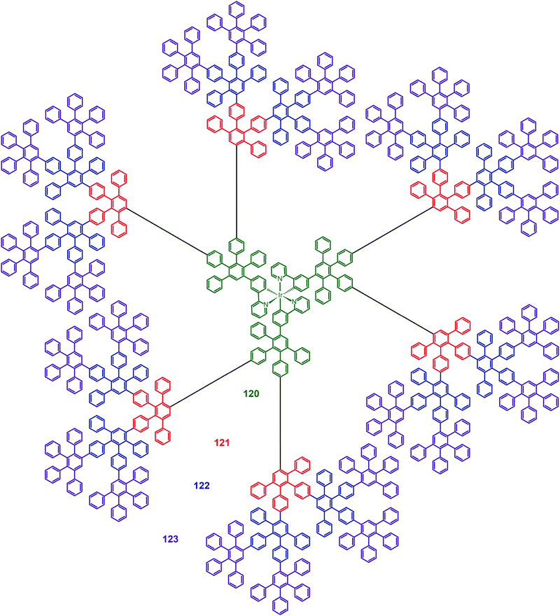
Müllen and co-workers reported in 2009 on a divergent approach to prepare high generation (up to fourth) polyphenylene dendrimers (120–123) with an Ir(III) core.59 These hybranched Müllen-type dendrons can fill the empty space surrounding the core to the greatest extent. Complex 123, which has nine phenyl groups spanning from the outer shell to the Ir(III) core, is perhaps the largest Ir(III) dendrimer reported thus far. The energy transfer between discrete Ir(III) cores can be efficiently suppressed due to the enormous size of the dendrons. The emission profiles of complex 123 in solid state and in solution were similar, with emission peaks at around 516 nm. The nondoped spin-coated devices incorporating complex 122 exhibited the best electroluminescence performance among the dendrimers under investigation, with a high current efficiency of 21.9 cd A−1 and an external quantum efficiency of 6.1%. The pioneering work of Müllen on Ir(III) dendrimers has provided a platform upon which new and emerging applications could be established.
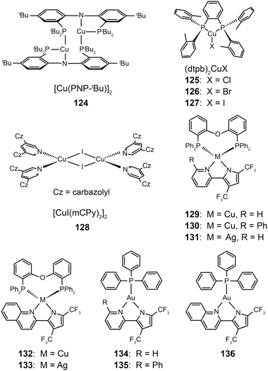
3.2.2.2 Green-emitting Cu(I) complexes. Cu(I) complexes are important green-emitting metallophosphors because of their high reliability, low cost and rich luminescent properties. However, tetrahedral Cu(I) complexes often exhibit weak luminescence intensities caused by the distortion of excited states and consequently non-radiative decay. One notable solution to this problem is to enhance the structural rigidity of the complexes by adding bulky ligands. Deaton et al. in 2010 reported the fabrication of OLEDS derived from a binuclear Cu(I) complex (124), leading to a high external quantum efficiency of 8.7% with the emission maximum at 512 nm.60 In the following year, Hashimoto et al. synthesized highly emissive three-coordinate Cu(I) complexes (125–127) with high degrees of symmetry.61 These complexes showed intense green emissions with high photoluminescence quantum yields (57–71%) in amorphous films. The OLEDs containing 126 in the emitting layer exhibited a low turn-on voltage of 2.7 V, a high current efficiency of 65.3 cd A−1, and a peak external quantum efficiency of 21.3%.
In 2011, Liu et al. developed a convenient route to high performance OLEDs based on green-emitting Cu(I) complexes as emissive layers (Fig. 11).62 In their design, they co-deposited 3,5-bis(carbazol-9-yl)pyridine (mCPy) and CuI to form a CuI complex as emissive material in OLEDs. The pyridine-based mCPy ligand serves a dual role as both a ligand for stabilizing the metal and an accommodating host material for the complex, thereby resulting in the formation of a uniform film of the [CuI(mCPy)2]2 complex (128). With a simple three-layer device structure, the authors achieved pure green luminescence at 530 nm, a maximum luminance of 9700 cd m−2, and a peak external quantum efficiency of 4.4%. In a separate note, Hsu et al. systematically investigated the influence of group 11 metal d-orbitals on the luminescence performance of the corresponding metal complexes (129–136).63 They showed that Cu(I) complexes exhibit a substantially higher rate of intersystem crossing and more efficient phosphorescence than their Ag(I) and Au(I) analogues. Among the series of metal d10-complexes studied, complex 129 exhibited the most intensive green emission with a photoluminescence quantum yield of 35% in the solid state. Although the maximum brightness of complex 129 is only ∼500 cd m−2, its doped devices yield peak electroluminescence efficiencies of 20.0 cd A−1, 14.9 lm W−1, and 6.6%.
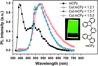 | ||
| Fig. 11 Photoluminescence spectra of a neat mCPy film (at 77 K) and CuI:mCPy films with different ratios at room temperature under excitation at 350 nm (inset: photographic image of a CuI:mCPy film excited at 365 nm using a UV lamp). (Reproduced with permission from ref. 62. Copyright 2011, American Chemical Society.) | ||
3.2.2.3 Green-emitting Pt(II) complexes. Square-planar Pt(II) complexes are commonly used as green phosphors in OLEDs. Characteristic reactions for these complexes are ligand substitution and oxidative addition. In 2007, Cocchi et al. constructed a series of terdentate cyclometallated Pt(II) complexes (137–142) for electroluminescence applications.64 The emissions of these complexes can be precisely tuned from green to yellow by varying the substituents on the N^C^N-coordinating ligand 1,3-di(2-pyridyl)benzene. The electron-donating substituents are able to considerably elevate HOMOs of the complexes and to facilitate hole injections. High efficiencies up to 16% for the peak external quantum efficiency and 40 cd A−1 for current efficiency were measured for OLEDs composed of Pt(II) complexes in a blended host matrix.
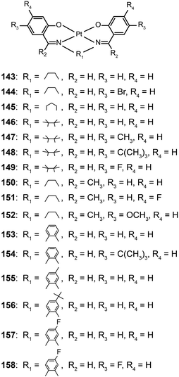
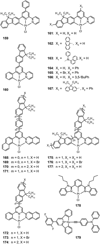
The Che group recently reported a series of highly luminescent Pt(II) complexes (143–158) with bidentate Schiff base ligands.65 As a result of ligand rigidity, these complexes have high thermal stability with Td values of more than 300 °C. The planar and conjugated structure of the Schiff base ligand benefits carrier injection and transport with HOMO and LUMO energies at −5.4 and −2.4 eV, respectively. The 146-doped devices achieved a bright green-yellowish emission, with a maximum luminance of 23![[thin space (1/6-em)]](https://www.rsc.org/images/entities/char_2009.gif) 000 cd m−2, a turn-on voltage of 4 V, and a high current efficiency of 31 cd A−1. To evaluate potential application in solution-processed devices, the same group further prepared a range of Pt(II) complexes (159–177) bearing tridentate ligands with fluorene oligomers.66 The utilization of oligomeric organic ligands coordinated to the metal ions offers the prospect of low-cost, solution-processable optoelectronic devices as the fluorene moieties increase the solubility of the complexes in common solvents. The extended π-conjugation can also induce bathochromic shifts in the emission of the complexes. The emission spectra (λmax = 558–601 nm) of these complexes feature a vibronic structure partially resolved as usually observed for fluorene-based polymers. High emission quantum yields up to 76% were attained in degassed dichloromethane. All of the complexes showed excellent carrier-injection abilities with HOMO and LUMO levels of −5.2 and −3.0 eV, respectively. The 164-doped devices achieved a maximum brightness of 27
000 cd m−2, a turn-on voltage of 4 V, and a high current efficiency of 31 cd A−1. To evaluate potential application in solution-processed devices, the same group further prepared a range of Pt(II) complexes (159–177) bearing tridentate ligands with fluorene oligomers.66 The utilization of oligomeric organic ligands coordinated to the metal ions offers the prospect of low-cost, solution-processable optoelectronic devices as the fluorene moieties increase the solubility of the complexes in common solvents. The extended π-conjugation can also induce bathochromic shifts in the emission of the complexes. The emission spectra (λmax = 558–601 nm) of these complexes feature a vibronic structure partially resolved as usually observed for fluorene-based polymers. High emission quantum yields up to 76% were attained in degassed dichloromethane. All of the complexes showed excellent carrier-injection abilities with HOMO and LUMO levels of −5.2 and −3.0 eV, respectively. The 164-doped devices achieved a maximum brightness of 27![[thin space (1/6-em)]](https://www.rsc.org/images/entities/char_2009.gif) 000 cd m−2 with maximum current (14.7 cd A−1) and luminous power efficiencies (9.2 lm W−1).
000 cd m−2 with maximum current (14.7 cd A−1) and luminous power efficiencies (9.2 lm W−1).
Recently, Tam et al. reported a dibenzimidazole-based Pt(II) complex (178).67 Large d–d orbital splitting caused by the anionic phenyl ligand reduces nonradiative energy transfer processes and improves the quantum yields of the complex to 19% in solution and 45% in solid state. The 178-doped devices yielded intensive green emission with high quantum (11.5%) and luminous power (27.2 lm W−1) efficiencies. The authors also developed a novel alkynylgold(III) compound (179) with much improved luminescence.68 The σ-donating alkynyl ligand strongly enhances the optical performance of the complex with a high quantum yield of 34% in poly(methyl methacrylate), and also provides main contribution to the HOMO energy level. As a result, a bright green electroluminescence with a peak at 528 nm was realized with high current (37.4 cd A−1), luminous power (26.2 lm W−1), and quantum efficiencies (11.5%).
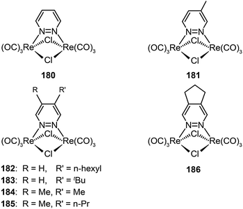
3.2.2.4 Green-emitting Re(I) complexes. To date, Re(I) complexes have not been subject to the same systematic treatment as other transition metal complexes, although the Re(I) complexes are known to exhibit bright photoluminescence. The main issue with the limited use of these complexes for device applications is their poor processability. Recently, Mauro et al. investigated a series of neutral, dinuclear, Re(I) complexes (180–186) as phosphorescent emitters in OLEDs.69 Through functionalization of diazine-based ligands with alkyl groups at different positions, the emission color of these complexes can be tuned from yellowish-green to orange, with high quantum yields up to 22%. These complexes also exhibited high electrochemical stability and suitable HOMO and LUMO energy levels for efficient carrier injection. Notably, the OLEDs obtained with complex 186, using spin-coating and vacuum evaporation, showed a turn-on voltage of 4.1 V and a maximum current efficiency of 11.0 cd A−1 at a luminance of 27 cd m−2.
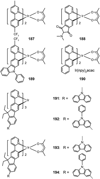
In 2008, Ho et al. developed a multifunctional Ir(III) complex 189, which features the substitution of an electron-withdrawing CF3 group on a phenylcarbazole-based ligand.72 The authors argued that the incorporation of the carbazolyl moiety can promote hole transport, while the CF3 group can suppress the self-quenching behavior and enhance the electron mobility. Remarkably, the CF3 substituent induced a 50 nm red shift, leading to an emission at 567 nm with a quantum yield of 19% in solution and a short lifetime of 0.58 μs. The devices derived from complex 189 generated a maximum current efficiency of 40 cd A−1, corresponding to an external quantum efficiency of 12% and a power efficiency of 24 lm W−1.
Replacement of the phenyl group in the Ir(ppy)2acac complex with a naphthyl group results in complex Ir(npy)2acac 190, which exhibits an emission at 550 nm.73 Complex 190 has a high quantum yield of 22% in solution and suitable HOMO and LUMO energy levels (−5.1 and −2.8 eV, respectively), making it a promising candidate for OLED applications. Indeed, the 190-doped devices achieved good quantum efficiency (10.5%) and luminous power efficiencies (21.8 lm W−1). The substitution of the phenyl group with fluorene or its derivatives also can lead to yellow/orange emissions due to the extension of π-conjugation.74 The resulting complexes 191–194 showed elevated HOMO levels for efficient carrier injection. In addition, the oligomeric ligand can also facilitate the formation of an amorphous state, enabling the fabrication of doped devices by wet-processing approaches. Among the series of fluorene-based complexes investigated, 192 supported its spin-coated doped devices with the highest electroluminescence efficiencies of 29.77 cd A−1, 13.35 lm W−1, and 9.58%.
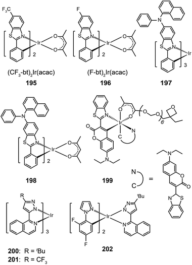
Ir(bt)2acac, which gives emission at 557 nm with a quantum yield of 26%, is one of the most popular orange-emitting complexes.75 Substitution of the benzothiazole unit with a CF3 group or a fluorine atom can shift the emission of (CF3-bt)2Ir(acac) (195) and (F-bt)2Ir(acac) (196) complexes to 564 and 554 nm, respectively.76 The devices prepared with these two complexes showed a low onset driving voltage of ∼4 V, a driving voltage of ∼10 V at brightness >60![[thin space (1/6-em)]](https://www.rsc.org/images/entities/char_2009.gif) 000 cd m−2, and high efficiencies (>20%, ∼40 lm W−1, 70 cd A−1). In comparison, the substitution by an electron-donating naphthylphenylamine group resulted in much larger bathochromic shifts (>20 nm) of the emission band position for Ir(III) complexes (197 and 198).77 The spectral shift mainly originates from the elevation of HOMO levels promoted by the aryl amine group. However, the quantum yields of the two complexes were lowered to 12% and 9%, presumably due to structural relaxation of the aryl amine group. The spin-coated doped devices of 197 and 198 gave moderate electroluminescence performance.
000 cd m−2, and high efficiencies (>20%, ∼40 lm W−1, 70 cd A−1). In comparison, the substitution by an electron-donating naphthylphenylamine group resulted in much larger bathochromic shifts (>20 nm) of the emission band position for Ir(III) complexes (197 and 198).77 The spectral shift mainly originates from the elevation of HOMO levels promoted by the aryl amine group. However, the quantum yields of the two complexes were lowered to 12% and 9%, presumably due to structural relaxation of the aryl amine group. The spin-coated doped devices of 197 and 198 gave moderate electroluminescence performance.
In 2008, Rehmann et al. reported a photo-crosslinkable Ir(III) complex (199; also known as x-emitter) containing oxetane moieties.78 For a well-balanced charge transport, the authors utilized an additional electron-conducting layer on top of the emissive layer, leading to significantly improved device performance. The spin-coated doped devices of 199 realized a maximum current efficiency of 18.4 cd A−1 at an operating voltage of 5 V and a brightness of 100 cd m−2. Notably, the maximum efficiency was improved by a factor of 30 relative to a device without the electron-transporting layer. Ir(bipz)3 (200) and Ir(fipz)3 (201) complexes were constructed by Chou and co-workers in 2010 according to a contrary strategy of utilizing high-field-strength ligands to induce hypochromatic shift in emission wavelength.79 These two complexes showed bright yellow luminescence with the emission peaks at 567 and 545 nm, respectively. The 200-doped devices exhibited higher efficiencies (14.6%, 26.1 lm W−1, 34.8 cd A−1) than those based on (dfpz)2Ir(bipz) complex (202) (11.6%, 17.6 lm W−1, 28.6 cd A−1). The high efficiencies for complex 200 result from the balancing effect of the ancillary ligand on carrier injection and transport.
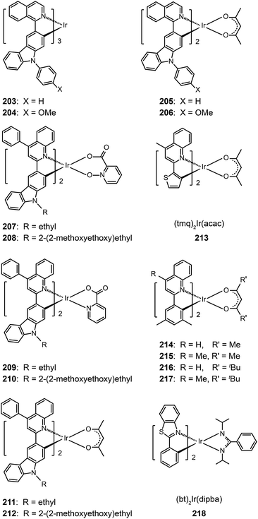
3.2.4.1 Red-emitting Ir(III) complexes. Owing to structural constraints and strong intermolecular interaction, red-emitting Ir(III) complexes often suffer from unbalanced carrier injection and transport, luminescence quenching, and poor device performance.80 Introduction of electron-donating groups can effectively enhance the carrier injecting/transporting ability.80 For instance, carbazole moieties in Ir(III) complexes (203–206) strongly elevate the HOMO levels of these complexes by coupling of the carbazole unit to the iridium isoquinoline core. They represent materials that emit in the red region of the optical spectrum with quantum yields up to 30%. These complexes also have excellent thermal and morphological stability (Td > 340 °C and glass transition temperature Tg > 110 °C). Complex 205 exhibited a higher external quantum efficiency (11.76%) than 203 (10.87%), which could be attributed to the suppression of nonradiative transitions by the high field strength of the acac ligand in 205. However, complex 203 displayed higher current (11.00 cd A−1) and power efficiencies (6.16 lm W−1) as compared with 205 (10.15 cd A−1, 5.25 lm W−1).
A similar effect of the carbazolyl group on quinoline-based Ir(III) complexes, (Et/EO-CVz-PhQ)2Ir(pic-N–O), (Et/EO-CVz-PhQ)2Ir(pic) and (Et/EO-CVz-PhQ)2Ir(acac) (207–212), was demonstrated by Lee et al.81 These complexes also have improved thermal and morphological stability with Td of 385–344 °C and Tg of 150–287 °C. The ancillary ligands showed a strong effect on the optical properties of the complexes. The acac-based complexes displayed much lower photoluminescence quantum yields (3–5%) than other complexes, of which 210 gave the highest quantum yield (33%). The emission peaks of the acac-based complexes are centered at around 623 nm, while the emissions of other complexes are at about 604 nm. Complex 208-doped spin-coated devices achieved the best electroluminescence performance. The maximum efficiencies reached 8.89 cd A−1, 3.41 lm W−1 and 5.51%. The carbazole group clearly improves the rigidity of the complexes and hence decreases the probability of nonradiative transition. The roll-offs of external quantum efficiency were less than 1% at 20 mA cm−2.
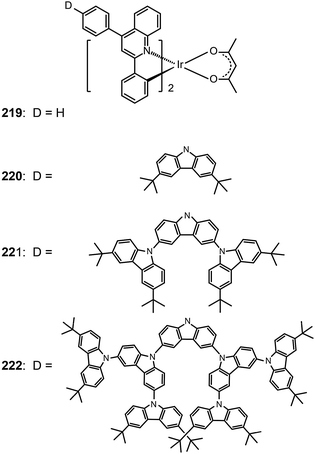
One common approach to suppress intermolecular interaction is to increase the steric hindrance of molecules by introducing bulky groups. A representative example was demonstrated in (tmq)2Ir(acac) complex (213) by substituting a methyl group at the 4-position of quinoline. Complex 213 emits at 611 nm with a full-width-at-half-maximum of 48 nm, which is much narrower than that of complex (piq)2Ir(acac).13 With a conventional 4,4′-bis(9-carbazolyl)-2,2′-biphenyl (CBP) host, complex 213 realized a low turn-on voltage of 3.2 V and a high luminance of 54![[thin space (1/6-em)]](https://www.rsc.org/images/entities/char_2009.gif) 508 cd m−2, as well as high efficiencies of 21.5 cd A−1, 19.3 lm W−1 and 15.1%. For (BIQS)/213-based devices, the best electroluminescence performance to date was obtained, including extremely high efficiencies of 37.3 cd A−1, 32.9 lm W−1, and 25.9%.13 The increase in the number of methyl and tert-butyl substituents in Ir(III) complexes (214–217) can further increase the intermolecular steric hindrance.82 The electron-donating methyl group induced the elevation of both HOMO and LUMO levels. The iso-propyl substituent in (bt)2Ir(dipba) complex (218) also revealed the ability to reduce intermolecular interaction.83 It was found that the use of the amidinate ligand changed HOMO and LUMO levels to −4.88 and −2.81 eV. The suppressed quenching effect due to enhanced carrier injection in 218 was confirmed using its heavily doped (30%) devices. Except for the low driving voltages of 2.5 V obtained for onset and 3.3 V at 100 cd m−2, high efficiencies of 18.1 cd A−1, 18.4 lm W−1, and 15.4% were also realized. The nondoped devices of 218 also achieved high efficiencies of 8.4 cd A−1, 6.9 lm W−1, and 7.5% reported thus far. Another notable development was reported by Ding et al., who showed that the use of dendritic protection, as shown in Ir(phq)2(acac)-type dendrimers (219–222), can improve electroluminescence performance.84 The efficiencies of nondoped devices based on 222 reached 3.3 cd A−1, 1.3 lm W−1, and 5.0%, while devices doped with 5% of 222 had the efficiencies of 13.0 cd A−1, 7.2 lm W−1, and 11.8%.
508 cd m−2, as well as high efficiencies of 21.5 cd A−1, 19.3 lm W−1 and 15.1%. For (BIQS)/213-based devices, the best electroluminescence performance to date was obtained, including extremely high efficiencies of 37.3 cd A−1, 32.9 lm W−1, and 25.9%.13 The increase in the number of methyl and tert-butyl substituents in Ir(III) complexes (214–217) can further increase the intermolecular steric hindrance.82 The electron-donating methyl group induced the elevation of both HOMO and LUMO levels. The iso-propyl substituent in (bt)2Ir(dipba) complex (218) also revealed the ability to reduce intermolecular interaction.83 It was found that the use of the amidinate ligand changed HOMO and LUMO levels to −4.88 and −2.81 eV. The suppressed quenching effect due to enhanced carrier injection in 218 was confirmed using its heavily doped (30%) devices. Except for the low driving voltages of 2.5 V obtained for onset and 3.3 V at 100 cd m−2, high efficiencies of 18.1 cd A−1, 18.4 lm W−1, and 15.4% were also realized. The nondoped devices of 218 also achieved high efficiencies of 8.4 cd A−1, 6.9 lm W−1, and 7.5% reported thus far. Another notable development was reported by Ding et al., who showed that the use of dendritic protection, as shown in Ir(phq)2(acac)-type dendrimers (219–222), can improve electroluminescence performance.84 The efficiencies of nondoped devices based on 222 reached 3.3 cd A−1, 1.3 lm W−1, and 5.0%, while devices doped with 5% of 222 had the efficiencies of 13.0 cd A−1, 7.2 lm W−1, and 11.8%.
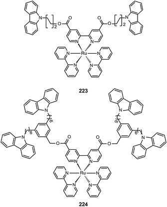
3.2.4.2 Red-emitting Ru(II) complexes. For the oxidation states (II–IV) of ruthenium, there is great complexity as many complexes can undergo reversible oxidation and reduction reactions. Ru(II) complexes with nitrogen-based ligands now attract great attention for application in OLEDs. Zhu et al. recently reported an intriguing class of phosphorescent ruthenium(II) complexes (223 and 224) with peripheral carbazole substituents. These complexes exhibit intense deep red emission at ∼660 nm, and can form high quality films using the electrochemical deposition technique.85 Despite the encapsulation of the Ru(II) core by the peripheral carbazole group, the optical properties of 223 and 224 are essentially unaltered. However, the HOMO energy levels of 223 and 224 are raised by 0.1 eV, while their LUMOs are reduced by 0.4 eV. The device made with 223 achieved maximum luminous current (3.9 cd A−1) and power efficiencies (1.1 lm W−1) at a maximum brightness of 293 cd m−2.
3.2.4.3 Red-emitting porphyrin-type complexes. Tetrapyrrole macrocyclic rings, such as porphyrins, are of major biological and medical importance. But as emitters for OLED applications, these compounds are conventionally thought to be constrained by the quenching effect because of strong intermolecular interaction. The quenching effect can be circumvented using donor–acceptor (D–A) systems. To prevent the potential phase separation during the preparation of the D–A system, Montes et al. designed Alq3-PtTPP-based systems (225–228), linked by oligofluorene bridges, for the investigation of triplet dynamics in D–A electroluminescent materials (Fig. 12).86 Importantly, the linkers facilitate exothermic triplet energy transfer. The red emission at ∼650 nm from PtTPP is sensitized by the Alq3 moiety. The nondoped spin-coated devices based on 225 and 226 achieved external quantum efficiencies of 0.21% and 0.18%, respectively.
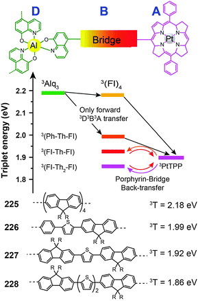 | ||
| Fig. 12 Intramolecular energy transfer involving compounds 225–228 (D, B and A refer to donor, bridge and acceptor, respectively). (Reproduced with permission from ref. 86. Copyright 2007, American Chemical Society.) | ||
3.2.4.4 Red-emitting Eu(III) complexes. Luminescent Eu(III) complexes are most famous for their intense monochromic red emissions at ∼615 nm with high quantum yields.87 As there are several excellent recent reviews on light-emitting lanthanide materials,88 we herein only focus on recent development of functional phosphine oxide-based Eu(III) complexes. Tertiary phosphine oxides are a series of oxide ligands having the general formula R3PO.89 They are obtained by oxidation of trisubstituted phosphines, and constitute one of a few series of ligands in which electronic and steric properties can be precisely controlled by varying R.
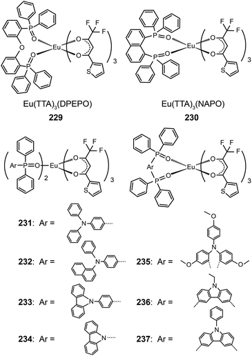
The Huang group presented first reports on the synthesis of electroluminescent Eu(III) complexes, Eu(TTA)3DPEPO (229)89a and Eu(TTA)3NAPO (230),89b,c with phosphine oxide chelating ligands. The phosphine oxide ligands form more stable coordination bonds with lanthanide ions compared with N-heterocyclic ligands, such as pyridine. The phosphine oxide complexes thus have high thermal and morphological stability (Td > 300 °C and Tg ≈ 100 °C). Complex 229 reveals a very high quantum yield of 0.55 owing to the reduction in nonradiative loss. The compact and rigid structure and strong electron-transporting ability of the PO ligand endow 229-coupled devices with very high efficiencies of 4.58 cd A−1, 2.05 lm W−1, and 2.89%.89a
The same group further prepared Eu(TTA)3(TAPO)2, Eu(TTA)3(NADAPO)2, Eu(TTA)3(CPPO)2, and Eu(TTA)3(CPO)2 complexes (231–234) with hole-transporting groups incorporated into monodentate ligands in order to balance the carrier injection and transport in emissive layers.90 These complexes have high quantum yields (up to 42%) that are attributable to the reduced quenching effect imparted by the bulky ligands. The hole-transporting groups enhanced the hole injection by elevating the HOMO level from −6.3 to about −5.5 eV. On the other hand, the LUMO levels of these complexes remained at −3.0 eV, which is similar to that of triphenylphosphine oxide-based Eu(III) complexes. The Eu(III) complex 232 with the bulkiest PO ligand in the series under investigation provided its nondoped devices with a high luminance of 59 cd m−1. The electroluminescence performance of devices doped with 232 is among the best results reported thus far, with maximum efficiencies of 5.88 cd A−1, 3.69 lm W−1 and 3.71%. In a following paper, the authors investigated the effect of different ligand structures on optoelectronic performance using D–A type Eu(III) complexes appended with PO ligands.91 They discovered that the reductive effect of Eu(III) ions induces the migration of electron cloud from electron-rich hole-transporting groups to electron-deficient PO groups. Consequently, the abilities of both functional groups to inject or transport charge carriers are weakened.
Nevertheless, the insertion of a π-spacer between the donor and the acceptor group of a ligand does effectively diminish the inductive effect of Eu(III) ions on frontier molecular orbital electron cloud distributions of the ligand. Xu et al. duplicated this strategy in Eu(TTA)3(TMOADPO), Eu(TTA)3(EtCzDPO), and Eu(TTA)3(PhCzDPO) complexes (235–237).92 The use of rigid bidentate ligands enhanced the thermal and morphological stability of the complexes and also reduced nonradiative transitions due to structural relaxation. The devices based on these complexes achieved a maximum luminance of >1000 cd m−2 and a high external quantum efficiency of >3.5%. By taking advantages of the strong chelating effect of the PO ligand toward lanthanide ions, the authors recently introduced PO-based Eu(III) complexes into polymeric light-emitting Eu(III) materials.93
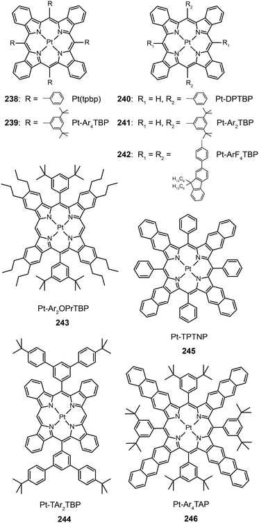
3.2.5.1 IR-emitting Pt(II) complexes. In 2007, the Thompson group reported the first highly efficient metalloporphyrin near-infrared (NIR) dye, Pt(tpbp) (238).95 The HOMO and LUMO levels of 238 are −4.9 and −2.5 eV, respectively, suitable for carrier injection. The strong emissive ability of this complex is manifested by its high quantum yield of 70%. Combined with an electron-transporting host Alq3, 238 exhibited an excellent electroluminescence performance with a high maximum output of 750 μW cm−2 and a maximum external quantum efficiency of 6.0%. The efficiency roll-off was gradual and the lifetime of the devices was measured up to 1000 h. However, the emission wavelength (765 nm) of this material is considered to be too short for optical communication applications. Recently, Graham et al. reported on the development of IR emissive Pt–porphyrin derivatives (239–246), with emission wavelength stretched out to 1022 nm for Pt–TPTNP complex 245 and Pt–Ar4TAP complex 246 by increasing the conjugation length from 238 (Fig. 13).96 However, 237 exhibited the worst electroluminescence performance with a maximum efficiency of only 0.2%. The Pt–porphyrin derivatives of 238, 239–244, with limited conjugation lengths have relatively high quantum yields of ∼45%. Their polymeric light-emitting devices achieved external quantum efficiencies of 2.07–3.2% using polyvinylcarbazole as the host. Their OLEDs made with Alq3 as the host realized high external quantum efficiencies of 5.0–9.2%.
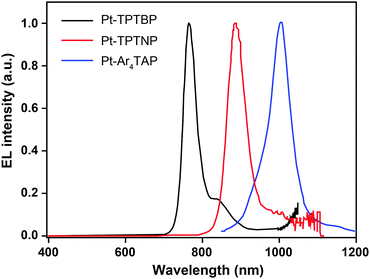 | ||
| Fig. 13 Electroluminescence spectra of PHOLEDs using 238, 245 and 246 as the emitter, respectively, in the PVK:PBD host matrix. The bathochromic shifts in emission from 750 to 1000 nm are due to conjugation extension from phenyl to naphthyl to anthryl in their porphyrin rings. (Reproduced with permission from ref. 96. Copyright 2011, American Chemical Society.) | ||
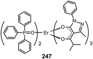
3.2.5.2 IR-emitting lanthanide complexes. Lanthanide-doped inorganic materials are well-known for their successful optical applications as upconversion emitters and fiber amplifiers in optical communications. The Piguet group has developed a series of lanthanide–transition metal hybrid complexes to realize upconversion processes at the molecular level.97 Common optical communication windows at 1550, 1300 and 980 nm correspond to the emission from Er(III), Nd(III) and Yb(III) complexes, respectively. Therefore, IR devices based on lanthanide complexes have been proposed. However, such developments are constrained by the strong absorption of IR radiation by C–H vibration and the inherent poor electrical properties of the complexes.87a A notable effort was demonstrated by Li et al., who reported the synthesis of an Er(PM)3(TP)2 complex (247) based on pyrazolone and TPPO ligands.98a The two ligands possess an antenna effect that enhances the emission from Er(III) at 1540 nm. The nondoped devices based on 247 achieved a maximum output of 0.21 μW cm−2.
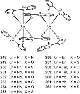
Katkova et al. prepared a range of NIR emitting Pr(III), Nd(III), Ho(III), Er(III), Tm(III), and Yb(III) complexes (248–262), sensitized by 2-(2-benzoimidazol-2-yl)phenolate, 2-(2-benzoxyazol-2-yl)phenolate or 2-(2-benzothiazol-2-yl)phenolate ligands.98b These complexes tend to form dimers comprising two lanthanide ions and six organic ligands. The nondoped devices of Nd(III) complexes 252 and 253 yielded strong light outputs at 1069 nm (74 and 29 μW cm−2, respectively), while their Yb(III) counterparts 261 and 262 exhibited much higher light outputs at 982 nm (154 and 286 μW cm−2, respectively).
Full-color phosphorescent OLEDs are now realized with extremely high efficiencies using various metal–organic complexes. For instance, external quantum efficiencies approaching 25% have been achieved for blue, green and red emissions (Table 2). Nevertheless, it is worth noting that efficient blue phosphors are less abundant due to the difficulty in achieving high energy metal-to-ligand charge-transfer (3MLCT) and ligand-to-ligand charge-transfer (3LLCT) states. Furthermore, relatively low performances of OLEDs are typically observed for red phosphors as they are prone to quenching. This stimulates continuing efforts to develop novel red-emitting complexes with low polarity, weak intermolecular interaction, and short emission lifetime.
| Emitter | Photophysical properties | HOMO/LUMOc (eV) | Device performance | Ref. | |||
|---|---|---|---|---|---|---|---|
| Emission peaka (nm) | Φ (%) | Voltage (V)d | Max. brightness (cd m−2) | Max. efficiencye | |||
| a Measured in solution. The values in parentheses indicate the shoulder peak. b Measured in solid matrices. c Measured according to the analysis of cyclic voltammetric data and energy bandgaps. d Turn-on voltage. e In the order of current efficiency (cd A−1), power efficiency (lm W−1) and external quantum efficiency (%). | |||||||
| 37 | 454(482), — | — | −6.2/−3.2 | ∼6 | ∼2000 | 36.1, 17.3, 23.3 | 23 |
| 49 | 455, — | — | 5.2/3.2 | 3.2 | 20![[thin space (1/6-em)]](https://www.rsc.org/images/entities/char_2009.gif) 649 649 |
22.3, 19.8, 15.1 | 30 |
| 56 | 458, — | — | — | 4 | — | 6.3, 4.0, 6.0 | 32 |
| 57 | 430(458), — | 0.11 | — | 5.4 | 1817 | 11.4, 7.9, 11.9 | 33 |
| 58 | 428(455), — | 0.4 | — | 4.4 | 4044 | 11.3, 8.6, 11.7 | 33 |
| 59 | 485(515), 510 | 3.81 | −5.51/−2.87 | 3.2 | 38![[thin space (1/6-em)]](https://www.rsc.org/images/entities/char_2009.gif) 963 963 |
25.45, 23.52, — | 34 |
| 66 | 468(495), — | 76 | — | <3.8 | — | 17, 14, 7.9 | 37 |
| 70 | 435(465), 438(466) | 94 | −5.4/−2.2 | — | — | 5.4, 3.4, 3.9 | 38 |
| 71 | — | 46 | — | — | — | 20.6, 6.4, 12.6 | 39 |
| 80 | 460, — | 7 | — | — | 1200 | 0.5, —, — | 41 |
| 84 | 441, — | 55 | — | — | — | 1.5, 0.52, — | 42 |
| 88 | 505, — | 40 | −5.22/−2.00 | 3.3 | 48![[thin space (1/6-em)]](https://www.rsc.org/images/entities/char_2009.gif) 295 295 |
35.02, 26.82, 11.05 | 47 |
| 93 | 536, — | — | −5.0/−2.5 | 3.4 | 69.0, 62.0, 18.7 | 48 | |
| 94 | 535, — | — | −5.1/−2.6 | 3.7 | 62.5, 53.1, 17.1 | 48 | |
| 95 | 480(510), 530 | 87 | — | 3.5 | 46![[thin space (1/6-em)]](https://www.rsc.org/images/entities/char_2009.gif) 808 808 |
123.5, 43.2, — | 49 |
| 96 | — | 95 | −5.1/−2.6 | — | — | 89.2, 69.8, 23.6 | 50 |
| 98 | 543, 553 | 30 | −4.78/−2.29 | 2.4 | — | —, 32.5, — | 51 |
| 101 | 491(517), — | 72 | −5.13/−2.9 | 2.5 | 6150 | —, —, 5.9 | 52 |
| 105 | 493(523), 520(528) | 37 | −5.36/−2.49 | 4.9 | 6255 | 15.41, 8.08, 4.68 | 53 |
| 115 | — | — | — | 3 | 3362 | 24.0, 16.7, 7.0 | 56 |
| 119 | 517, 521 | 83 | −5.06/−2.63 | — | 19![[thin space (1/6-em)]](https://www.rsc.org/images/entities/char_2009.gif) 000 000 |
45.7, 37.8, 13.4 | 58 |
| 128 | —, 495(528) | — | — | 3.6 | 9700 | 10.2, 13.8, 4.4 | 62 |
| 137 | 491, — | 60 | — | — | — | 40, —, 16 | 64 |
| 178 | 506(505b), — | 19 | −6.32/−3.86 | — | — | 38.9, 27.2, 11.5 | 67 |
| 179 | 669(537b), 590 | 0.85 | −5.6/−3.4 | — | — | 37.4, 26.2, 11.5 | 68 |
| 188 | 560(595), — | — | −5.8/−3.5 | 3.3 | — | 34.2, 31.0, 12.7 | 71 |
| 192 | 562(605), 561(610) | 12 | −4.96, −2.54 | 6.7 | 21![[thin space (1/6-em)]](https://www.rsc.org/images/entities/char_2009.gif) 570 570 |
29.77, 13.35, 9.58 | 74 |
| 195 | 564(600), — | 36 | 4.0 | 80![[thin space (1/6-em)]](https://www.rsc.org/images/entities/char_2009.gif) 190 190 |
76.0, 39.8, 27.2 | 76 | |
| 203 | 620, 608(658) | 19 | −4.96/−2.43 | 4.6 | 5846 | 11.0, 6.16, 10.87 | 80 |
| 213 | 611, — | 55 | — | 3.1 | 58![[thin space (1/6-em)]](https://www.rsc.org/images/entities/char_2009.gif) 688 688 |
37.3, 32.9, 25.9 | 13 |
| 218 | 609–616 | — | −4.88/−2.81 | 2.5 | 15![[thin space (1/6-em)]](https://www.rsc.org/images/entities/char_2009.gif) 701 701 |
8.4, 6.9, 7.5 | 83 |
| 232 | 611, 615 | 36.1 | −5.29/−3.08 | 4.8 | 1158 | 5.88, 3.69, 3.71 | 90 |
| 236 | 612, 615 | 36.3 | −5.56/−3.21 | 7.6 | 1276 | 5.60, 2.26, 3.54 | 92 |
| 238 | 765, — | — | −4.9/−2.5 | — | 740(μW cm−2) | —, —, 6.3 | 95 |
3.3 Recent progress on metal complex-based OLEDs
Since the invention of OLEDs, the device fabrication has been inseparable from the synthesis of organic materials. The first two-layer sandwich-type configuration designed by Tang and Van Slyke2 has led to a remarkable improvement in the maximum brightness of OLEDs and a significant reduction in the driving voltage from hundreds of volts for bulk single-crystal devices to just a few volts. This achievement clearly underscores the paramount importance of device fabrication in improving the overall electroluminescence performance. Till the present time, there are three major types of organic light-emitting devices, namely organic light-emitting diodes,18d,99 light-emitting electrochemical cells (LECs),100 and organic light-emitting transistors (OLETs).101Rapid patterning of metal cathodes onto different substrates is an important issue for high throughput, large-scale production of OLEDs.103 Lee102 and Chae103 developed a simple but practical technology named selective metal transfer (SMT) (Fig. 14). This technology obviates the need for a mask or mold typically required in conventional techniques involving either vacuum evaporation or screen printing. The adhesion strength of the Al metal strongly depends on the surface properties of the polymer used. Polyvinylcarbazole (PVK) and poly[2-methoxy-5-(2′-ethyl-hexyloxy)-1,4-phenylene vinylene] (MEH-PPV) have a much stronger adhesion strength with Al surface than hydrophilic poly(vinyl pyrrolidone) (PVP). This difference can be utilized to selectively transfer Al onto PVK-containing emissive layers.
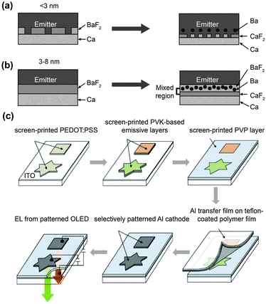 | ||
| Fig. 14 (a and b) Formation of a triple-layer cathode of BaF2:Ba/CaF2/Ca adjacent to an emitting layer by the reaction of BaF2 with Ca layers. (a) With a thickness of BaF2 less than 3 nm, direct contact between Ca and emitting layers facilitates nonradiative decay of excitons. (b) With a BaF2 thickness of greater than 3 nm, a complete trilayer cathode can be formed to realize both efficient electron injection and the separation of Ca and emitting layers. (c) Schematic showing the fabrication procedure of patterned Al cathodes on the surface of PVK-containing emitting layers by a selective metal transfer technique. (Reproduced with permission from ref. 102 and 103. Copyright 2009 and 2011, Wiley-VCH Verlag GmbH & Co. KGaA.) | ||
Indium tin oxide (ITO) is a common anode material for OLEDs due to the close match of its high work function to the HOMO level of organic semiconductors and its high transmittance to visible light. However, the high cost and difficult processing procedure of ITO limit its commercial applications in OLEDs. Therefore, solution-processable, conductive carbon-based anode materials become an attractive candidate for the replacement of ITO.
Ou et al. used a PEDOT:PSS composite (PSC) to modify the morphology of carbon nanotubes (CNTs) (Fig. 15a and b).104 When treated with PSC, the CNT thin film anode exhibited a 40–70% reduction in roughness. The thin film anode also showed an excellent tensile strength as compared with ITO-based anodes. The utilization of CNTs remarkably improved the electroluminescence performance of the devices with a high luminance of over 8000 cd m−2 and a maximum efficiency of 10.7 cd A−1. Relative to CNT, graphene has a high carrier mobility and a comparable resistance and light outcoupling properties. The sheet resistance (Rsh) of a graphene film can be estimated according to eqn (5):
 | (5) |
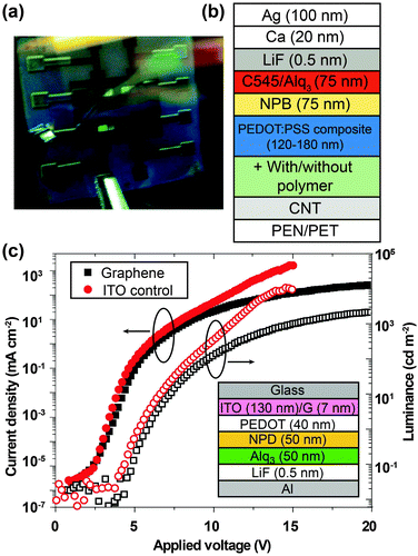 | ||
| Fig. 15 (a) Photographic image of devices made with a carbon nanotube anode. (b) The corresponding device configuration. (c) The brightness–current density–voltage curves of the devices using graphene as the anode (inset: device configuration). (Reproduced with permission from ref. 104 and 105. Copyright 2009, American Chemical Society.) | ||
Wu et al. prepared graphene films with a thickness of ∼7 nm and a surface roughness less than 3 nm (Fig. 15c).105 The driving voltages of the graphene-based devices, obtained at 4.5 V for onset and 11.7 V for 100 cd m−2, are comparable to those of ITO-based devices with 3.8 and 9.9 V for onset and 100 cd m−2, respectively. However, the efficiencies of the graphene-based devices were slightly lower than those of ITO-based devices because of the higher sheet resistance and mismatched work function of the graphene film. Matyba et al. further replaced the metal cathode and the ITO anode with graphene and PEDOT:PSS, respectively, to construct a solution-processible LEC based on full carbon materials.106 They constructed the emitting layer with a blend of a light-emitting polymer, a ‘super yellow’ dye, and an electrolyte. The authors reasoned that the ions generated by dissolution of the electrolyte can rearrange at the interface between the emitting layer and the electrode and facilitate carrier injection, thus providing a solution to the high-work-function issue (4.2–4.6 eV) of the graphene. As a result, this type of devices achieved a low turn-on voltage of 2.8 V. Both transparent electrodes of graphene and PEDOT:PSS supported the double-side emissions with similar maximum brightness (∼1000 cd m−2 for each side).
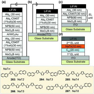 | ||
| Fig. 16 (a and b) Device configurations of a double-unit tandem OLED and a single-unit OLED. (c and d) Device configurations of a single-unit OLED and a double-unit tandem OLED modified with a charge-generating bilayer of NaTn/C60. (Reproduced with permission from ref. 107d and 108. Copyright 2007 and 2011, respectively, American Institute of Physics and Royal Society of Chemistry.) | ||
Hamwi et al. reported the utility of an intriguing design, based on an interconnecting unit that consists of a CsCO3-doped 4,7-diphenyl-1,10-phenanthroline (BPhen) layer and a WO3 film, for remarkably improved electroluminescence performance.109 They used 4,4′,4′′-tris(N-carbazolyl)-triphenylamine (TCTA) and 1,3,5-tri(1-phenyl-1H-benzo[d]imidazol-2-yl)phenyl (TPBI) as the hole-transporting layer and the electron-transporting layer, respectively. The charge generation and separation mainly occurred at the interface between the WO3 film and the hole-transporting layer. The CsCO3-doped BPhen layer enables rapid electron transport into the TPBI layer (Fig. 17a). Cesium azide (CsN3) was also doped in the electron-transporting layer because of its high chemical stability in air and its low evaporation temperature.110 The tandem OLEDs containing the interconnector of MoO3/BPhen:CsN3 realized a very high current efficiency over 80 cd A−1 (Fig. 17b). Recently, Perumal et al.111 utilized the same concept of doped carrier transporting layers in tandem OLEDs (Fig. 17c). In their studies, the charge carriers were generated in carrier transporting layers under alternating current rather than injection through external electrodes. The maximum brightness (∼1000 cd m−2) of this type of devices indicates their potential use for display and lighting applications.
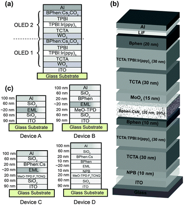 | ||
| Fig. 17 Device configurations of tandem OLEDs using organic–inorganic hybrids, including (a) BPhen:Cs2CO3, (b) BPhen:CsN3 and (c) BPhen:Cs, as the charge generation layer. (Reproduced with permission from ref. 109–111. Copyright 2010 and 2012, Wiley-VCH Verlag GmbH & Co. KGaA.) | ||
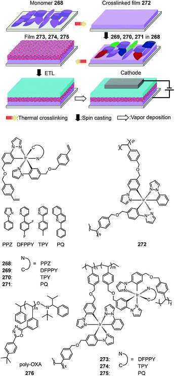 | ||
| Fig. 18 procedure of solution-processed multi-layer devices on the basis of crosslinkable monomers 268–271 and the corresponding crosslinked polymers 272–275. (Reproduced with permission from ref. 116. Copyright 2009, Wiley-VCH Verlag GmbH & Co. KGaA.) | ||
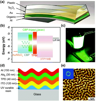 | ||
| Fig. 19 (a) Device configuration of a PHOLED using Ta2O5 as the light out-coupling layer. (b) The energy level diagram of active layers used in PHOLEDs. (c) The photographic image of the device in operation. (d) A quasi-periodic buckling structure designed for enhancing light out-coupling. (e) Topographic AFM image of buckling patterns formed by a 10 nm-thick aluminium layer. (Reproduced with permission from ref. 117a and b. Copyright 2011 and 2010, Nature Publishing Group.) | ||
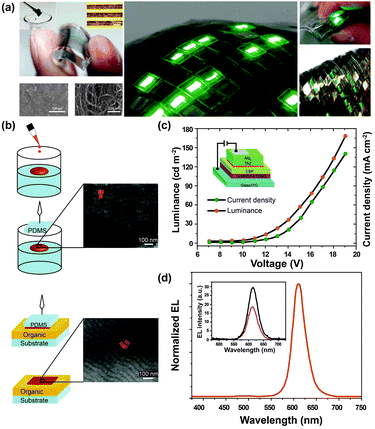 | ||
| Fig. 20 (a) Characterization of stretchable PHOLEDs derived from printable elastic conductors comprising single-walled carbon nanotubes (SWNTs) uniformly dispersed in a fluorinated rubber. (b) Fabrication procedure for multilayer inorganic/organic polarized OLED devices with aligned nanorods as confirmed by TEM characterization. (c) Brightness–J-voltage curves and (d) electroluminescence spectrum of the nanorod-based OLEDs (insets show device configuration and the electroluminescence spectra in two orthogonal directions, respectively). (Reproduced with permission from ref. 119a and 120. Copyright 2009, Nature Publishing Group and American Chemical Society, respectively.) | ||
Another noteworthy development is the fabrication of polarized LED devices that would largely benefit general illumination with an improved contrast and minimize eye discomfort. In 2009, Rizzo et al. reported an interesting organic/inorganic polarized LED device based on ordered arrays of semiconducting nanorods (Fig. 20b–d).120 Using a solution-based processing method, the authors prepared CdSe@CdS core–shell nanorod-based films aligned in smectic or nematic phases on water surface. The films were subsequently transferred to LED devices by a contact printing technique. Charge injection and transportation in these devices were modified with organic carrier transporting layers. Polarized emissions along the nanorod alignment direction were observed from the nanorods with a maximum brightness of 170 cd m−2 and a maximum current efficiency of 0.24 cd A−1.
A substantial improvement over emission performance can be achieved using an OLET with a stacked trilayer configuration, in which hole- and electron-transporting layers are inserted between source/drain, the dielectric layer and emission layers to balance the flux of carriers. A representative example was demonstrated by Capelli et al., who fabricated a trilayer OLET with the maximum luminance greater than 200 nW and the peak external quantum efficiency exceeding 4%.121 In their design, Alq3 doped with 4-(dicyanomethylene)-2-methyl-6-(p-dimethylaminostyryl)-4H-pyran (DCM) was used as the emission layer, while thiophene derivatives, DH-4T (277) and DFH-4T (278), were used as hole- and electron-transporting layers, respectively (Fig. 21a and b). However, the requirement of a relatively high gate voltage for the OLETs is still a problem for their application.
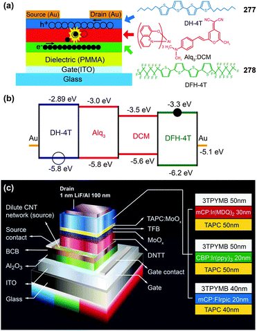 | ||
| Fig. 21 (a and b) Device configuration and energy level scheme of a trilayer OLET using Alq3:DCM, DH-4T and DFH-4T as emitting, hole-transporting, and electron-transporting layers, respectively. (c) Device structures of a trilayer OLET with direct integration of red, green and blue OLED and OTFT. (Reproduced with permission from ref. 8 and 121. Copyright 2011 and 2010, respectively, American Association for the Advancement of Science and Nature Publishing Group.) | ||
McCarthy et al.8 recently reported active matrix displays using highly efficient OLETs with low driving voltage and low power dissipation (Fig. 21c). The key design is the use of a thin film of single-wall carbon nanotubes that permits the organic semiconductors to drive the high currents needed by OLED pixels, but at much lower operating voltages. The resulting OLETs achieved a high luminance of ∼10![[thin space (1/6-em)]](https://www.rsc.org/images/entities/char_2009.gif) 000 cd m−2 at a driving voltage of less than 10 V. Efficiencies of the devices obtained are comparable to those of conventional PHOLEDs, with ∼13 cd A−1 for red, ∼50 cd A−1 for green and ∼25 cd A−1 for blue. Significantly, the on/off states of these OLET displays can be readily switched by applying negative and positive gate voltages, thus offering potential applications in the fabrication of simplified pixels for active matrix displays.
000 cd m−2 at a driving voltage of less than 10 V. Efficiencies of the devices obtained are comparable to those of conventional PHOLEDs, with ∼13 cd A−1 for red, ∼50 cd A−1 for green and ∼25 cd A−1 for blue. Significantly, the on/off states of these OLET displays can be readily switched by applying negative and positive gate voltages, thus offering potential applications in the fabrication of simplified pixels for active matrix displays.
In general, the low efficiency of electroluminescent devices is the most important limiting factor that stands in the way of using OLEDs for practical applications. The development of outcoupling technology and integrated device configurations, such as tandem OLEDs and OLETs, would be likely to satisfy the constraints associated with current electroluminescent devices. For outcoupling technology, a key issue that needs to be addressed is to improve the performance of thin film-type coupling materials. Tandem OLEDs offer several advantages in terms of technological feasibility for enhancing efficiencies and realizing white emissions. However, this kind of devices suffer from repeatability problems as defects present even in a single layer would lead to significantly reduced performance. We believe that OLETs are more promising to be commercialized because of their reduced fabrication costs and new functionalities as well as easy integration in different substrates.
4. Photovoltaic complexes for OPVs
Most of the energy available to us on this planet comes from the Sun. Although the amount of solar energy reaching the Earth is enormous, only a small fraction of the energy is used to support life. Almost 30% of incoming solar radiation is immediately reflected back into space as short-wave radiation, while nearly half is converted to heat. The growing demand for sustainable energy supplies has triggered a rapid development of photovoltaic devices that can tap into the massive source of solar energy by converting sunlight into electrical current. These devices can be divided into five categories based on inorganic semiconductors (InGaN, GaN, GaAs, etc.), silicon (single crystal, polycrystalline, amorphous, etc.), dye-sensitizers (Ru-based complexes, quantum dots, etc.), organic compounds, and recently reported perovskite materials. In particular, solution-processable all-solid organic photovoltaics (OPVs) work well in all light conditions and have much greater flexibility.122 Over the past two years, we have seen an impressive acceleration in the field of OPVs. In 2011, Mitsubishi Chemical reportedly set a record conversion efficiency of 9.2%. In 2013, the Yang group updated the conversion efficiency over 10% using tandem device structures.123 However, the technical challenge remains for material synthesis and device fabrication, particularly for organic solar cells requiring low batch-to-batch variation in conversion efficiency.124The layout of active layers, adopting either bilayer, grade, bulk, inverted,125a or tandem125b,c cell structures, significantly impacts the overall performance of the resulting OPVs (Fig. 22).126 When selecting organic materials for photovoltaic devices, one needs to consider the following criteria: (i) organic semiconductors with high absorption coefficients for efficiently harvesting sunlight; (ii) suitable heterojunctions for separating photogenerated excitons; (iii) compatible HOMO and LUMO levels and high charge mobility for efficient transfer of the separated charge carries to the electrodes; (iv) high stability of the materials and long operating lifetimes of the devices; (v) good solution processability; and (vi) good scalability of the materials and devices for large area applications.
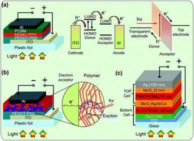 | ||
| Fig. 22 General device designs of OPVs in (a) bilayer, (b) bulk, and (c) tandem heterojunction solar cells. (Reproduced with permission from ref. 126a–c. Copyright 2007, 2013 and 2010, respectively, American Chemical Society, In-Tech Open Access Publisher and American Institute of Physics.) | ||
It is imperative that a bicontinuous network, characterized by a domain width of ∼20 nm (approximately twice that of the exciton diffusion length) and a high donor/acceptor interfacial area,112d favors the dissociation of excitons and the transport of the separated charge carriers to the collecting electrodes.124 To achieve high efficiencies, the difference between the LUMO levels of the donors and acceptors needs to be within ∼0.3 eV to facilitate the dissociation of the excitons, and a bandgap in the range of 1.2–1.7 eV is preferred to allow maximal absorption of sunlight. This would correspond to donor HOMO levels of −5.2 to −5.7 eV to provide a large open-circuit voltage (Voc), when [6,6]-phenyl-C61-butyric acid methyl ester (PCBM) with a LUMO level of approximately −4.3 eV is used as the acceptor (Fig. 23).127 In addition, the material should possess a charge transfer channel with high charge carrier mobility and thus high short-circuit current density (Jsc) for high-efficiency carrier separation and collection at a given distance from the electrodes.128 It should be noticed that morphology adjustment of the active composite layer plays a very important role too.112a Bad morphology of the active layer will lead to a low fill factor (FF). Therefore, an ideal material used for PCBM-based bulk OPV devices should have the following attributes: a HOMO level lower than −5.20 eV, a bandgap in the range of 1.30–1.90 eV, and a hole mobility greater than 1 × 10⁻³ cm2 V−1 s−1 (Fig. 24).129
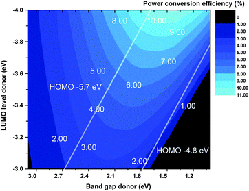 | ||
| Fig. 24 Theoretical relations between the power conversion efficiency and the HOMO level of the donors in PCBM-based bulk OPVs. (Reproduced with permission from ref. 129. Copyright 2006, Wiley-VCH Verlag GmbH & Co. KGaA.) | ||
Several methods have been developed to minimize the energy loss of OPV devices by fine-tuning the bandgap and frontier orbital energy levels of organic semiconducting materials. These include D–A hybrid architecture, copolymerization, molecular topology, and supramolecular alignment.130 Despite their usefulness in tuning the HOMO and LUMO levels, most of the organic molecules reported to date do not fulfill the stringent requirements as ideal donors for OPVs. Fig. 25 lists some widely used building blocks for donor molecules, which have been designed and assessed in bulk-heterojunction OPV devices.131 These building blocks are usually covalently attached to newly designed molecules to prepare desirable OPV materials.132
Although organic oligomers and polymers, such as polythiophenes, dominate the field of OPVs,133 their metal-containing derivatives represent another important class of organic semiconductors.134,135 Metal ions may provide redox-active and paramagnetic centers to generate active species for charge transport and thus greatly alter the electronic and optical properties of the organic π-systems. As already discussed in previous sections, the introduction of heavy metals into the organic system promotes the formation of triplet excited states. The lifetime of triplet excited states is typically in the microsecond regime, which is three orders of magnitude longer than the nanosecond decays typically observed for singlet excited states in conjugated molecules. Given that a significant increase in lifetime should lead to a longer exciton diffusion length, the use of metal–organic complexes would be attractive for developing highly efficient photovoltaic devices.
4.1 Porphyrins and phthalocyanines
Porphyrins and phthalocyanines are highly conjugated macrocyclic systems (26 π electrons) that exhibit excellent thermal and chemical stability.136 These macrocycles also possess tunable flexibility over their electronic and optical properties either by varying the functional group at the peripheral position of the molecules or by introducing an appropriate metal atom (Cu, Zn, Al, and Ti as shown in complexes 279–282) into the interior region of the macrocycles.136a In view of their large extinction coefficients and strong absorbing ability in the NIR range, porphyrins and phthalocyanines have been investigated for decades as photodynamic therapy (PDT) agencies to convert light into heat.136b,c Therefore, wide chemical modification approaches and the great impacts on the molecular packing models and optoelectronic properties have made them intensively investigated as the active layer in organic optoelectronic devices. In addition, porphyrins and phthalocyanines can act as either a donor or an acceptor in the photovoltaic cells, depending on the electron-donating/accepting characteristics of the substitutions.The first report on using metal-free porphyrins as donors in solar cells was in 1992 with a conversion efficiency of only 0.03%.137 In 2007, Sun et al.138 found that liquid crystalline porphyrin derivatives, substituted with long alkyl groups, have broad absorption wavelengths, closely matched energy levels with the PCBM acceptor and the electrodes, and unique homeotropical alignment in deposited films. The bulk heterojunction OPV cells showed conversion efficiencies of up to 0.78%. In 2011, Ryuzaki et al.139 took one step further and synthesized a zinc-coordinated porphyrin complex (283). The authors carefully examined the structural effect of 283 used as a donor molecule on the conversion efficiency of OPV cells [ITO/283/C60/Al]. They found that a crystalline film of 283 favors intermolecular charge transfer when compared to its amorphous counterpart, leading to increased mobility of charge carriers and thus enhanced conversion efficiencies. It should be noted that metal–porphyrin complexes are mainly used as sensitizers in dye-sensitized solar cells. These complexes are rarely used as active layers in heterojunction solar cells, largely due to their poor charge transport properties.140
In contrast to porphyrins, phthalocyanines exhibit excellent charge transport characteristics, thereby enabling their promising application in organic optoelectronics. In particular, metal–phthalocyanine complexes have gained increasing attention. CuPc (284) is the first OPV material, reported by Tang in 1986,4 with 1% conversion efficiency obtained from its two-layer structured device under simulated air-mass2 illumination. In a recent development, Roy and co-workers141a reported bulk heterojunction OPV cells, based on tetramethyl-substituted Cu(II) phthalocyanine complex (285). Complex 285 displayed excellent photovoltaic performance with a Jsc of 16.3 mA cm−2, a larger Voc of 0.58 V, a FF of 0.56, and a conversion efficiency of 5.3%.141b
When the copper in phthalocyanine complexes is replaced with aluminium chloride as shown in Al(III) complex (286), a non-planar phthalocyanine structure forms as evident by a significant absorption peak at 755 nm.142 A systematic investigation of the interfacial properties of ClAlPc–C60 organic heterojunctions in an inverted device configuration143 showed that the complex 286 adopts a lying configuration after being vacuum-deposited along with C60 onto an ITO electrode. This structure promoted charge transport in heterojunction-based solar cell devices and resulted in a relatively large Voc of 0.67 V, in contrast to 0.37 V obtained in the 284/C60-based device. Consequently, the complex exhibited high device performance with conversion efficiencies of >4% (Fig. 26).144
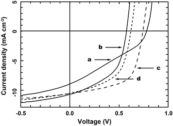 | ||
| Fig. 26 Current density vs. voltage (J–V) curves under 100 mW cm−2 air mass 1.5G simulated solar illumination, of (a) ITO/MoO3/286:C60 (105 °C)/C60/BCP/Ag; (b) ITO/MoO3/FDTS/286:C60 (105 °C)/C60/BCP/Ag; (c) ITO/MoO3/286 (105 °C)/C60/BCP/Ag; and (d) ITO/MoO3/FDTS/286 (105 °C)/C60/BCP/Ag. (Reproduced with permission from ref. 144. Copyright 2010, Elsevier B.V.) | ||
Like copper and aluminium, zinc also shows good device performance when incorporated in phthalocyanine. Meiss et al.145 prepared an efficient single bulk heterojunction organic solar cell with a power conversion efficiency of 4.6%. The solar cell was based on a blend of a fluorinated zinc phthalocyanine (287, M = Zn) as an electron donor and fullerene C60 as an electron acceptor. When boron was introduced into phthalocyanine, the researchers still observed fairly good OPV performance. Pandey et al.146 made both bilayer and bulk OPV devices with boron subphthalocyanine chloride (288) and C60. The conversion efficiencies of the devices reached 3.05 and 3.44%, respectively. Additional information about using boron subphthalocyanines as an emerging class of high performance organoelectronic materials can be found in a recent review.147
Fischer et al.148 reported a highly soluble ruthenium phthalocyanine complex (289) using pyridine-functionalized dendritic oligothiophenes as axial ligands. The solution-processed bulk heterojunction solar cells derived from 289 showed a high conversion efficiency (∼1.6%). Additionally, rare-earth metals can be incorporated into the phthalocyanine ligand. For example, Wang et al.149 used Sm3+ to prepare a layered structure of phthalocyanine. They found that the hybrid solar cells possess the capability to harvest light with a broad wavelength range from UV-visible to NIR. In other attempts, Honda et al.150 synthesized a silicon phthalocyanine derivative (290) and incorporated it into a bulk solar cell of poly(3-hexylthiophene) (P3HT) and PCBM. They observed an increased short-circuit current density and improved overall conversion efficiency by 20%.
Because of the low solubility of most phthalocyanine-based molecules in typical organic solvents, their devices were mostly fabricated by vacuum-deposited techniques. This significantly limits their application in solution-processed heterojunction solar cells. By introducing soluble long alkyl substitutes, Hori et al.151 prepared a soluble, mesogenic phthalocyanine derivative of 1,4,8,11,15,18,22,25-octahexylphthalocyanine (C6PcH2). Bulk heterojunction solar cells, fabricated by spin-coating of a mixed solution of C6PcH2 and PCBM, showed an energy conversion efficiency of 3.2%. For researchers working in the field of porphyrin- and phthalocyanine-based photovoltaic cells, we suggest further reading of the recent literature on state-of-the-art methodology.152
4.2 Pt(II) complexes
Pt(II) complexes are famous for their anticancer activity. They also possess excellent optoelectronic properties that are suitable for application in OPVs, mainly due to their square planar structure and relatively strong Pt–Pt interaction.153 Thus far, Pt(II)-containing polyethynylene (291),6 cyclometalated Pt(II) (292),154 and bis(8-hydroxyquinolinato) Pt(II) (293)155 complexes are among the most extensively investigated Pt(II) complexes for OPVs. When platinum ions are conjugated with alkyne units to form a one-dimensional polymer chain, the d-orbitals of the platinum ions overlap with the p-orbitals of the alkyne units, leading to an enhancement of both π-electron delocalization and intra-chain charge transport along the polymer chain. This orbital overlap enhances the spin–orbit coupling and facilitates intersystem crossing from the singlet to triplet manifolds, thereby enhancing the formation of triplet excitons with extended diffusion lengths.156 Another key advantage of using Pt(II) complexes is their good solubility in common solvents enabling film fabrication via solution processing.157The first report on the photovoltaic effect in a wide bandgap Pt(II) polyyne was by Köhler et al.158 in 1994, with a quantum yield up to 0.6%. Two years later, the same group improved the quantum yield up to ∼2% in an OPV device that contains 7 wt% of C60 to serve as an electron acceptor and assist in the dissociation of excitons.159 For the most part, research into the electron transfer from the Pt(II)–polyyne donor to the C60 acceptor explained away the efficiency enhancement. The authors attributed it to ionization of the triplet exciton in the Pt(II)–polyyne complex.
In 2007, Wong et al.6 reported an interesting platinum metallopolyyne polymer (294) with a low-bandgap π-conjugation by employing a D–A molecular design (Fig. 27). Based on ninety OPV cells fabricated, the authors obtained remarkably high, albeit debatable,160 conversion efficiencies (up to 5%).6 Several years later, Wang et al.161 further developed a new solution-processable Pt(II) metallopolyyne polymer (295) functionalized with both triphenylamine and 2,1,3-benzothiadiazole in a donor–π bridge–acceptor–π bridge–donor (D–π–A–π–D) motif. The best conversion efficiency of 1.61% was achieved with Voc of 0.77 V, Jsc of 4.94 mA cm−2, and FF of 0.39 when illuminated with an air mass 1.5 solar cell simulator. Recently, they extended the use of the D–A motif to prepare a series of soluble Pt(II) metallopolyynes, for example complex 296, containing Zn(II) porphyrin chromophores.162 These metallopolymers blended with PCBM showed a maximum conversion efficiency of 1.04%, with Voc of 0.77 V, Jsc of 3.42 mA cm−2, and FF of 0.39. OPV devices with further improved conversion efficiencies were fabricated by Wong and co-workers using Pt(II)-containing triphenylamine-based pseudo-3D polymers163 or bis(aryleneethynylene)-derived compounds (297).164
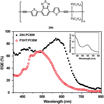 | ||
| Fig. 27 Absorption wavelength-dependent external quantum efficiencies of an OPV device containing Pt(II)-based organometallic D–A conjugated polymers (inset: absorption spectra of 294). (Reproduced with permission from ref. 6. Copyright 2007, Nature Publishing Group.) | ||
Several other groups have also made significant contributions to development of Pt(II)-based complexes for OPVs. Li et al.165 prepared a solution-processable acetylide polymer (298) functionalized with an electron-deficient anthraquinone spacer. Optical spectroscopy and electrochemical data revealed that 298 had a narrow bandgap and intra-molecular charge transfer occurred along the polymer backbone through involvement of the D–A structural motif. Li et al.165 also found that the insertion of an anthraquinone unit between thiophene fragments, as shown in complex 299, can expand the width of the absorption band for sunlight harvesting. Wu et al.166 prepared Pt(II)-bridged organometallic D–A conjugated polymers (300 and 301) by incorporating various electron acceptors via Sonogashira reaction. The OPV device made of 300 reached a high conversion efficiency of 2.4%, which is in good agreement with the value of 2.2% theoretically predicted by Janssen and co-workers.160 Clem et al.154 reported the test of a series of low-bandgap cyclometalated Pt(II) polymer complexes (302 and 303) for OPVs. Their corresponding photovoltaic devices yielded conversion efficiencies up to 1.3%.
4.3 Other metal complexes
Despite the dominant use of Pt(II) complexes for OPVs over the past two decades, other metal complexes, however, are gaining momentum. For instance, Ru(II) complexes, especially N719 dye (304),167 have been demonstrated to produce high short-circuit current in dye-sensitized solar cells (DSSCs). These Ru(II) complexes feature broad UV-visible absorption bands and relatively long excited-state lifetimes, resulting in respectable conversion efficiencies (higher than 10%). Wang et al.168a introduced a [Ru(bpy)3]2+ coordination complex (305) to a polyimide to prepare photovoltaic materials. The open-circuit voltages of the corresponding OPV devices were determined within the range of 0.19–0.52 V. Low et al.155 also reported the replacement of Pt with Ni and Cu metals chelated to the 5,7-dimethyl-8-hydroxy-quinoline (HMe2q) ligand. However, no photovoltaic phenomena were observed for the devices derived from [Ni(Me2q)2] (306) and [Cu(Me2q)2] (307) complexes. A fairly good power conversion efficiency of 2.8% was achieved by Fleetham et al.168b using a bilayer device made from a cyclometalated Ir(III) complex (308) and C60. Despite having an estimated exciton energy of only 1.55 eV, 308 rendered its device a dramatically improved Voc (1 V).In 2013, a record conversion efficiency of 15.4% was achieved by perovskite solar cells using a metal–organic complex, namely CH3NH3Pb(I,Cl)3, as the photoactive layer.169a The perovskite solar cells are one kind of DSSCs with a typical heterojunction configuration. The perovskite with the same structure as calcium titanium dioxide shows a broad absorption edge beyond 1000 nm, enabling improved harvesting of solar energy.169b Furthermore, the special metal–organic structure endows CH3NH3Pb(I,Cl)3 with ambipolar characteristics to afford excellent electrical performance. Therefore, high charge mobility, long lifetime, and large diffusion distance (0.1–1 μm) of the generated carriers should be the main factors responsible for the high conversion efficiency of the perovskite solar cells.169c,d
Table 3 shows the electronic properties and device performance for a wide range of metal complexes used as donors in OPVs. As discussed previously, an ideal donor for OPVs should have a broad absorption band in the solar spectrum to ensure an effective harvesting of the solar photons, and a high charge carrier mobility for hole and electron transport. The donor should also have a low-lying HOMO energy level for a large Voc and a suitable LUMO energy level to provide enough offset for charge separation. Furthermore, the energy levels of the polymer complexes must match those of the fullerides (e.g., PCBM) used in bulk heterojunction solar cells. It is clear that the complexes based on phthalocyanines and Pt(II) arylene ethynylenes meet the abovementioned criteria to improve the performance of OPVs. Apart from these two candidates, much remains to be learned from exploring other organometallic heterojunction materials for OPVs. In comparison with the low-bandgap polymers used in metal-free OPVs, the metal complexes as those described above generally allow facile control over absorption characteristics, energy levels, and charge-carrier mobilities via ligand substitution and modification. Through optimum design of devices and subtle control over the interaction between an organic chelating ligand and a suitable metal, synergistic effects can be harnessed to drastically boost the efficiency of the corresponding solar cells.
| Emitter | Building blocksa | Abs. (nm) | HOMO | LUMO | Acceptor | V oc (V) | J sc (mA cm−2) | PCEd (%) | Ref. | ||
|---|---|---|---|---|---|---|---|---|---|---|---|
| B1 | B2 | B3 | |||||||||
| a The first (B1), second (B2), and/or third (B3) building blocks of donors. b Open-circuit voltage (Voc) in V. c Short-circuit current density (Jsc) in mA cm−2. d Power conversion efficiency (PCE). | |||||||||||
| 294 | 291 | C13 | −5.37 | −3.14 | PCBM | 0.82 | 15.4 | 4.93 | 6 | ||
| 286 | 286 | C60 | 0.74 | 10.7 | 4.80 | 144 | |||||
| 287 | 285 | C60 | 0.69 | 12.1 | 4.60 | 145 | |||||
| 288 | 287 | C60 | 1.10 | 7.10 | 3.44 | 146 | |||||
| 294 | 291 | C13 | 380, 572 | −5.15 | −3.02 | PC71BM | 0.77 | 9.65 | 2.41 | 166 | |
| 293 | 293 | C60 | 0.42 | 14.8 | 2.4 | 155 | |||||
| 295 | 291 | C9 | C7 | 380, 539 | −5.78 | −3.46 | PCBM | 0.78 | 4.94 | 1.61 | 161 |
| 309 | 289 | C9 | 348, 651 | −5.13 | −3.58 | PCBM | 0.56 | 8.3 | 1.60 | 148 | |
| 310 | 291 | C10 | C4 | 264, 430 | −5.51 | −3.00 | PCBM | 0.79 | 4.06 | 1.29 | 170 |
| 302 | 292 | C11 | 375, 520 | −5.40 | −3.75 | PCBM | 0.65 | 5.3 | 1.29 | 154 | |
| 311 | 291 | C9 | C3 | 363, 484 | −6.09 | −3.31 | PCBM | 0.80 | 4.00 | 1.09 | 161 |
| 312 | 291 | C5a | C4 | −5.53 | −3.71 | PCBM | 0.77 | 3.42 | 1.04 | 162 | |
| 284 | 284 | Perylene | 0.45 | 2.3 | 0.95 | 4 | |||||
| 297 | 291 | C13 | C4 | 398, 546 | −5.20 | −3.17 | PC71BM | 0.68 | 4.21 | 0.71 | 166 |
| 296 | 291 | C5a | C1 | −5.58 | −3.64 | PCBM | 0.72 | 2.74 | 0.68 | 162 | |
| 303 | 292 | C4 | 335, 610 | −5.60 | −3.50 | PCBM | 0.38 | 3.5 | 0.40 | 154 | |
| 300 | 291 | C15a | 415, 674 | −4.82 | −3.11 | PC71BM | 0.52 | 2.71 | 0.36 | 166 | |
| 299 | 291 | C3 | C4 | −5.96 | −3.78 | PCBM | 0.78 | 1.40 | 0.35 | 165 | |
| 301 | 291 | C13 | C11 | 402, 540 | −5.23 | −3.09 | PC71BM | 0.64 | 2.35 | 0.31 | 166 |
| 298 | 291 | C3 | −6.06 | −3.76 | PCBM | 0.70 | 0.14 | 0.03 | 165 | ||
5. TTA-based upconversion emission materials
Organic materials with fluorescence emission usually follow the famous principle of the Stokes' law, meaning that output photon energy is weaker than input photon energy. Anti-Stokes emission by two-photon absorption (TPA) that converts two low-energy pump photons into a high energy emitting photon was first observed in 1961 by Kaiser and Garrett in a CaF2:Eu(II) crystal sample.171 Anti-Stokes emission or photon upconversion is a distinct optical process characterized by the emission of photons with energies 10–100 times kT greater than the excitation energy.1725.1 Theory of TTA-based upconversion
Over the past decades, significant efforts have been devoted to the research of lanthanide-based materials that are essential to many aspects of our life.172 The lanthanides are a family of fifteen highly electropositive metals in the f-block that falls between the s- and d-block. In contrast to the wide variation in properties across each series of transition metals, the chemical properties of the lanthanides are remarkably uniform because of the shielding by the 5s- and 5p-electrons. The electron transitions within the 4fn configuration of the lanthanides made possible the discovery of many fascinating optical properties, such as photon upconversion first introduced in the mid-1960s by Auzel, Ovsyankin, and Feofilov.172 When compared to conventional anti-Stokes processes such as TPA, photon upconversion emission is based on physically existing energy states, allowing for frequency conversion with much higher efficiency.Unlike the well-established upconversion involving lanthanide-doped phosphors or nanocrystals,173–182 upconversion based on organic molecules has not been widely reported, much of which is due to the high excitation intensity (on the order of MW cm−2) required for organic molecules.183 Recently, a new approach has been proposed involving the TTA of excitons in organic molecules where an upconversion-induced delayed fluorescence occurs. This approach requires two molecular entities that can interact in a triplet state to produce one molecular entity in an excited singlet state and another in its ground singlet state. This bimolecule-based upconversion process does not need a coherence excitation and the required excitation power density (a few mW cm−2) is significantly lower than that for TPA.184 The latter characteristic of TTA is particularly attractive for OPVs given that direct use of normal sunlight (power density of AM1.5G: ∼100 mW cm−2) has an intuitive plausibility.
The upconversion-induced delayed fluorescence supported by bimolecular TTA generally involves a three-step process (Fig. 28). First, a phosphorescent donor molecule is excited from its ground state to a singlet excited state, followed by intersystem crossing to an excited triplet state. The second step is characterized by the triplet–triplet energy transfer occurring between the donor molecule and a nearby emitting acceptor. Subsequent collision of the acceptor molecules at the excited triplet state results in an energy level twice that of the lowest triplet energy gap.
For TTA-based upconversion, the triplet state of the donor molecule should have a relatively long lifetime to ensure energy transfer to the triplet state of the acceptor molecule. In recent years, many groups185 have demonstrated that the incorporation of metal–organic chromophores can markedly enhance upconversion yields because the metal center enables the population of the triplet state of the sensitizers with high efficiency following absorption of single photons.
5.2 Pd(II) complex-based sensitizers
In a study published in 2007,186 a team led by Stanislav Baluschev looked into upconversion of excitation at ∼700 nm (1 W cm−2) to blue-green emission (480–580 nm) using a sensitizer–emitter couple based on a Pd(II)–porphyrin complex (313 or 314) and bis(tetracene) (315) (Fig. 29). The external yield of this upconversion system was estimated to be more than 4%. The anti-Stokes shift between the excitation and the emission for the sensitizer–emitter couple was estimated to be as large as 0.7 eV.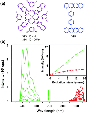 | ||
| Fig. 29 (a) TTA systems based on the coupling of a Pd(II)–porphyrin complex 313 (or 314) with bis(tetracene) 315. (b) Emission spectra of 313 (red lines) and 313:315 (green lines) in toluene by a single-mode CW diode laser excitation at 695 nm with different intensities (inset: integral intensity comparison of emission from 313 (red circles) and 313:315 (green circles)). (Reproduced with permission from ref. 186. Copyright 2007, Wiley-VCH Verlag GmbH & Co. KGaA.) | ||
Noncoherent TTA-based upconversion is typically observed in solution. Islangulov et al.187 have taken one step further and reported noncoherent low-power upconversion in solid polymer films by blending high concentrations of Pd(II) octaethylporphyrin (PdOEP: 316) sensitizer and 9,10-diphenylanthracene (DPA: 317) emitter within a rubbery host polymer. The upconversion through delayed singlet fluorescence of 317 was confirmed by quadratic incident power dependence studies and time-resolved emission data. These measurements indicate that the triplet sensitization of 317 can take place by selective excitation of 316. This work also provides evidence that the use of a host polymer is quite effective for achieving TTA-based upconversion in the solid state.
5.3 Ru(II) complex-based sensitizers
In 2011, Ji et al.188 reported a series of pyrene-containing Ru(II) polyimine complexes (318–322) with long-lived intraligand (3IL) excited states. The lifetime of the Ru(II) complex can be substantially prolonged by switching the emissive state from its usual 3MLCT to 3IL excited states, or by establishing an equilibrium between 3MLCT and 3IL excited states. [Ru(bpy)2Phen]2+319 shows a typical 3MLCT emission with a lifetime of 0.45 μs. [Ru(bpy)2PEPhen]2+322 has an 3IL excited state with a lifetime of 58.4 μs, which is much longer than that of 319 (Fig. 30). An equilibrium between the 3MLCT and 3IL excited states of [Ru(bpy)2PPhen]2+321 results in a lifetime of 9.22 μs. The upconversion was studied using 317 as an acceptor. The anti-Stokes shift obtained is 0.48 eV, from 473 nm of the laser excitation to 400 nm in emission. [Ru(bpy)2PEPhen]2+322 showed the strongest upconverted fluorescence, while 319 gave rise to a very week upconverted fluorescence. These data suggest that 3IL excited states are much more efficient in sensitizing the TTA-based upconversion than 3MLCT excited states.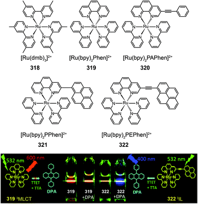 | ||
| Fig. 30 Molecular structures of Ru(II) sensitizers 318–322 and photographic images of upconversion emissions by 319 and 322. (Reproduced with permission from ref. 188. Copyright 2011, Wiley-VCH Verlag GmbH & Co. KGaA.) | ||
Another interesting investigation was reported by Singh-Rachford et al.189 using a conjugated supermolecule Pyr1RuPZn2 (323) with appreciably long lifetime of excited states (τ > μs) as the sensitizer and N,N-bis(ethylpropyl)perylene-3,4,9,10-tetracarboxylicdiimide (PDI; 324) as the acceptor. The selective NIR excitation at 780 nm of 323 in a solution containing 324 gives rise to a large anti-Stokes shift with an energy gain of 0.7 eV, resulting in the generation of yellow fluorescence at 541 nm.
5.4 BODIPY-type sensitizers
In addition to heavy metal-containing organic complexes, molecules based on a single chromophore of boron-dipyrromethene (BODIPY) also can be used as triplet sensitizers for TTA upconversion.190a Wu et al.190b reported a two BODIPY-derived sensitizers (325 and 326) with absorption in the range of 510–629 nm and long-lived triplet excited states of up to 66.3 μs. Upconversion emission with ΦUC up to 6.1% was observed for the samples dissolved in solution or dispersed in polymer films using 1-chloro-9,10-bis(phenylethynyl)anthracene (CBPEA; 327) as an acceptor.In summary, TTA-based upconversion offers tunable excitation and emission wavelengths by independent selection of sensitizers and annihilators. The high absorption coefficient (∼10−17 cm−2) of the available sensitizers enables the realization of high upconversion quantum yield under a low-threshold excitation. When compared to photon upconversion involving lanthanide doping, TTA-based upconversion seems to be more efficient with quantum yields (>5%) that are generally higher than those of lanthanide-doped NaYF4 upconversion nanoparticles (<3%). Another notable advantage of TTA-based upconversion is the ability to precisely control excitation and emission combinations, such as NIR-to-green186 and red-to-blue,191 while there is relatively limited access to tunable emission wavelengths from upconversion nanoparticles due to the shortage of efficient lanthanide activators. Nevertheless, upconversion nanoparticles can realize larger anti-Stokes shifts owing to the involvement of three, four and even five photon upconversion processes. Furthermore, as a bimolecular system, the TTA upconversion material may face constraints in dynamic systems and in vivo applications because the intermolecular interactions between the donor and the acceptor would be strongly influenced by environmental factors.
6. Conclusions and perspectives
The increasing awareness of the benefit of metal–organic complexes for optoelectronic applications has fuelled a growing demand for new approaches to prepare more complex molecular structures with tunable optical and electronic properties. The performance in certain aspects of these judiciously designed metal–organic complexes has even exceeded that of pure organic compounds. This improvement signifies the importance of metal coordination in controlling photophysical properties of the complexes. We anticipate that new developments, which may shape the future of optoelectronic technology, will be on the rise in the following areas.(i) Multifunctionalization. The limited availability of photofunctional complexes will drive innovative strategies for molecular multifunctionalization.192–196 The post-functionalization approach through direct modification of existing metal–organic complexes can simplify material design and render the complexes with well-defined optoelectronic properties and much improved device performance.
(ii) New theories and viewpoints. Will our classical theoretical bases always be intact when applied to grasp the mechanisms underlying the beneficial effects of metal–organic coordination? Perhaps this will not be the case. New models and challenging views, including the design of blue-emitting phosphors and elongation of the lifetime of 3IL excited states for TTA, could have a profound effect on the development of highly efficient optoelectronic materials.197–202
(iii) Improvement on device compatibility. There are important challenges to be tackled with the rise of flexible devices, in large part owing to the differences between the properties of inorganic and organic compounds. New device configurations and fabrication technologies, such as roll-to-roll technology, will take place in developing stretchable and biocompatible optoelectronic devices.119b
Abbreviations
| A | Acceptor |
| Alq3 | Tris(8-quinolinolato) aluminum(III) |
| BCP | 2,9-Dimethyl-4,7-diphenyl-1,10-phenanthroline |
| BIQS | Bis(4-(6H-indolo[2,3-b]quinoxalin-6-yl)phenyl)diphenylsilane |
| BODIPY | Boron-dipyrromethene |
| Bphen | 4,7-Diphenyl-1,10-phenanthroline |
| CBP | 4,4′-Bis(9-carbazolyl)-2,2′-biphenyl |
| CBPEA | 1-Chloro-9,10-bis(phenylethynyl)anthracene |
| CE | Current efficiency |
| CF3 | Trifluoromethyl |
| CIE | Commission internationale de L'Eclairage |
| ClAlPc | Chloroaluminium phthalocyanine |
| CNT | Carbon nanotube |
| C6PcH2 | 1,4,8,11,15,18,22,25-Octahexylphthalocyanine |
| CuPc | Copper(II) phthalocyanine |
| D | Donor |
| DCM | 4-(Dicyanomethylene)-2-methyl-6-(p-dimethylaminostyryl)-4H-pyran |
| DPA | 9,10-Diphenylanthracene |
| DSSC | Dye sensitized solar cell |
| EL | Electroluminescence |
| EQE | External quantum efficiency |
| FF | Fill factor |
| Firpic | Bis[(4,6-difluorophenyl)pyridinato-N,C2′]iridium(III)picolinate |
| FRET | Förster resonance energy transfer |
| HMe2q | 5,7-Dimethyl-8-hydroxy-quinoline |
| HOMO | Highest occupied molecular orbital |
| 3IL | Intraligand |
| IR | Infrared |
| ISC | Intersystem crossing |
| ITO | Indium tin oxide |
| J sc | Short-circuit current density |
| LEC | Light-emitting electrochemical cell |
| 3LLCT | Ligand-to-ligand charge-transfer state |
| LUMO | Lowest unoccupied molecular orbital |
| MEH-PPV | Poly[2-methoxy-5-(2′-ethyl-hexyloxy)-1,4-phenylene vinylene] |
| 3MLCT | Metal-to-ligand charge-transfer state |
| NIR | Near-infrared |
| NPB (NPD) | N,N′-Diphenyl-N,N′-bis(1-naphthyl)(1,1′-biphenyl)-4,4′diamine |
| OLED | Organic light-emitting diode |
| OLET | Organic light-emitting transistor |
| OPV | Organic photovoltaic |
| P3HT | Poly(3-hexylthiophene) |
| PBD | 2-(4-Biphenyl)-5-(4-tert-butylphenyl)-1,3,4-oxadiazole |
| PCBM | [6,6]-Phenyl-C61 butyric acid methyl ester |
| PC71BM | [6,6]-Phenyl-C71 butyric acid methyl ester |
| PCE | Power conversion efficiency |
| PDI | N,N-Bis(ethylpropyl)perylene-3,4,9,10-tetracarboxylicdiimide |
| PE | Power efficiency |
| PEDOT:PSS | Poly(3,4-ethylenedioxythiophene): poly(styrenesulfonate) |
| PHOLED | Phosphorescent organic light-emitting diode |
| PL | Photoluminescence |
| POSS | Polyhedral oligomeric silsesquioxanes |
| PSC | PEDOT:PSS composite |
| PVK | Polyvinylcarbazole |
| PVP | Poly(vinyl pyrrolidone) |
| SCNT | Singe-walled carbon nanotube |
| ScPc2 | Scandium diphthalocyanine |
| SMT | Selective metal transfer |
| TCTA | 4,4′,4′′-Tris(carbazol-9-yl)-triphenylamine |
| T d | Decomposition temperature |
| TFT | Thin-film transistor |
| T g | Glass transition temperature |
| 2-TNATA | 4,4′,4′′-Tris[2-naphthyl(phenyl)amino] triphenylamine |
| TPA | Two-photon absorption |
| TPBI | 1,3,5-Tri(1-phenyl-1H-benzo[d]imidazol-2-yl)phenyl |
| TPD | N,N′-Diphenyl-N,N′-bis(3-methylphenyl)-[1,1′-biphenyl]-4,4′-diamine |
| TPP | Triphenylphosphine |
| TPPO | Triphenylphosphine oxide |
| TTA | Triplet–triplet annihilation |
| TTET | Triplet–triplet energy transfer |
| V oc | Open-circuit voltage |
Acknowledgements
H.X. acknowledges financial support from the National Natural Science Fund of China (NSFC, 61176020 and 51373050), the New Century Excellent Talents Supporting Program of MOE (NCET-12-0706), and the Key Project of MOE (212039). W.H. acknowledges financial support from the National Basic Research Program of China (973 Program, 2009CB930601), NSFC (BZ2010043, 21274065, 20974046, 20774043, 51173081, 50428303, 61136003) and the Natural Science Foundation of Jiangsu Province (BK2008053, BK2009025, BK2011751, 10KJB510013). X.L. acknowledges the National Research Foundation and the Economic Development Board (Singapore-Peking-Oxford Research Enterprise, COY-15-EWI-RCFSA/N197-1), the Ministry of Education (MOE2010-T2-1-083), and the Agency for Science, Technology and Research (A*STAR) for providing support during the time this review was written.References
- D. D. Eley, Nature, 1948, 162, 819 CrossRef CAS.
- C. W. Tang and S. A. Van Slyke, Appl. Phys. Lett., 1987, 51, 913–915 CrossRef CAS PubMed.
- M. A. Baldo, D. F. O'Brien, Y. You, A. Shoustikov, S. Sibley, M. E. Thompson and S. R. Forrest, Nature, 1998, 395, 151–154 CrossRef CAS PubMed.
- C. W. Tang, Appl. Phys. Lett., 1986, 48, 183–185 CrossRef CAS PubMed.
- J. S. Shirk, J. R. Lindle, F. J. Bartoli and M. E. Boyle, J. Phys. Chem., 1992, 96, 5847–5852 CrossRef CAS.
- W.-Y. Wong, X.-Z. Wang, Z. He, A. B. Djurisic, C.-T. Yip, K.-Y. Cheung, H. Wang, C. S. K. Mak and W.-K. Chan, Nat. Mater., 2007, 6, 521–527 CrossRef CAS PubMed.
- S. Reineke, F. Lindner, G. Schwartz, N. Seidler, K. Walzer, B. Lussem and K. Leo, Nature, 2009, 459, 234–238 CrossRef CAS PubMed.
- M. A. McCarthy, B. Liu, E. P. Donoghue, I. Kravchenko, D. Y. Kim, F. So and A. G. Rinzler, Science, 2011, 332, 570–573 CrossRef CAS PubMed.
- Q. Liu, T. Yang, W. Feng and F. Li, J. Am. Chem. Soc., 2012, 134, 5390–5397 CrossRef CAS PubMed.
- T. Förster, Ann. Phys., 1948, 437, 55–75 CrossRef.
- D. L. Dexter, J. Chem. Phys., 1953, 21, 836–850 CrossRef CAS PubMed.
- S. J. Su, C. Cai and J. Kido, Chem. Mater., 2011, 23, 274–284 CrossRef CAS.
- C.-H. Fan, P. Sun, T.-H. Su and C.-H. Cheng, Adv. Mater., 2011, 23, 2981–2985 CrossRef CAS PubMed.
- H.-H. Chou and C.-H. Cheng, Adv. Mater., 2010, 22, 2468–2471 CrossRef CAS PubMed.
- (a) L. S. Sapochak, A. Padmaperuma, N. Washton, F. Endrino, G. T. Schmett, J. Marshall, D. Fogarty, P. E. Burrows and S. R. Forrest, J. Am. Chem. Soc., 2001, 123, 6300–6307 CrossRef CAS PubMed; (b) H.-J. Son, W.-S. Han, J.-Y. Chun, B.-K. Kang, S.-N. Kwon, J. Ko, S. J. Han, C. Lee, S. J. Kim and S. O. Kang, Inorg. Chem., 2008, 47, 5666–5676 CrossRef CAS PubMed; (c) H. Xu, Z.-F. Xu, Z.-Y. Yue, P.-F. Yan, B. Wang, L.-W. Jia, G.-M. Li, W.-B. Sun and J.-W. Zhang, J. Phys. Chem. C, 2008, 112, 15517–15525 CrossRef CAS; (d) H.-P. Zeng, G.-R. Wang, G.-C. Zeng and J. Li, Dyes Pigm., 2009, 83, 155–161 CrossRef CAS PubMed; (e) S.-G. Roh, Y.-H. Kim, K. D. Seo, D. H. Lee, H. K. Kim, Y.-I. Park, J.-W. Park and J.-H. Lee, Adv. Funct. Mater., 2009, 19, 1663–1671 CrossRef CAS; (f) C. Perez-Bolivar, S.-y. Takizawa, G. Nishimura, V. A. Montes and P. Anzenbacher, Chem.–Eur. J., 2011, 17, 9076–9082 CrossRef CAS PubMed.
- S.-H. Liao, J.-R. Shiu, S.-W. Liu, S.-J. Yeh, Y.-H. Chen, C.-T. Chen, T. J. Chow and C.-I. Wu, J. Am. Chem. Soc., 2009, 131, 763–777 CrossRef CAS PubMed.
- B. Xu, L. Chen, X. Liu, H. Zhou, H. Xu, X. Fang and Y. Wang, Appl. Phys. Lett., 2008, 92, 103305 CrossRef PubMed.
- (a) P.-T. Chou and Y. Chi, Chem.–Eur. J., 2007, 13, 380–395 CrossRef CAS PubMed; (b) L. Xiao, Z. Chen, B. Qu, J. Luo, S. Kong, Q. Gong and J. Kido, Adv. Mater., 2011, 23, 926–952 CrossRef CAS PubMed; (c) Y. Chi and P.-T. Chou, Chem. Soc. Rev., 2010, 39, 638–655 RSC; (d) S.-H. Hwang, C. N. Moorefield and G. R. Newkome, Chem. Soc. Rev., 2008, 37, 2543–2557 RSC.
- R. J. Holmes, S. R. Forrest, Y.-J. Tung, R. C. Kwong, J. J. Brown, S. Garon and M. E. Thompson, Appl. Phys. Lett., 2003, 82, 2422–2424 CrossRef CAS PubMed.
- A. B. Tamayo, S. Garon, T. Sajoto, P. I. Djurovich, I. M. Tsyba, R. Bau and M. E. Thompson, Inorg. Chem., 2005, 44, 8723–8732 CrossRef CAS PubMed.
- S. J. Lee, K.-M. Park, K. Yang and Y. Kang, Inorg. Chem., 2009, 48, 1030–1037 CrossRef CAS PubMed.
- S.-C. Lee and Y. S. Kim, Mol. Cryst. Liq. Cryst., 2008, 491, 209–216 CrossRef CAS.
- H.-J. Seo, K.-M. Yoo, M. Song, J. S. Park, S.-H. Jin, Y. I. Kim and J.-J. Kim, Org. Electron., 2010, 11, 564–572 CrossRef CAS PubMed.
- D. Di Censo, S. Fantacci, F. De Angelis, C. Klein, N. Evans, K. Kalyanasundaram, H. J. Bolink, M. Gratzel and M. K. Nazeeruddin, Inorg. Chem., 2008, 47, 980–989 CrossRef CAS PubMed.
- Y.-M. Wang, F. Teng, L.-H. Gan, H.-M. Liu, X.-H. Zhang, W.-F. Fu, Y.-S. Wang and X.-R. Xu, J. Phys. Chem. C, 2008, 112, 4743–4747 CAS.
- H. W. Ham, I. J. Kim and Y. S. Kim, Mol. Cryst. Liq. Cryst., 2009, 505, 130/[368]–138/[376] Search PubMed.
- S. Y. Ahn and Y. Ha, Mol. Cryst. Liq. Cryst., 2010, 530, 116/[272]–122/[278] Search PubMed.
- T. Sajoto, P. I. Djurovich, A. Tamayo, M. Yousufuddin, R. Bau, M. E. Thompson, R. J. Holmes and S. R. Forrest, Inorg. Chem., 2005, 44, 7992–8003 CrossRef CAS PubMed.
- R. J. Holmes, S. R. Forrest, T. Sajoto, A. Tamayo, P. I. Djurovich, M. E. Thompson, J. Brooks, Y.-J. Tung, B. W. D'Andrade, M. S. Weaver, R. C. Kwong and J. J. Brown, Appl. Phys. Lett., 2005, 87, 243507 CrossRef PubMed.
- K.-Y. Lu, H.-H. Chou, C.-H. Hsieh, Y.-H. O. Yang, H.-R. Tsai, H.-Y. Tsai, L.-C. Hsu, C.-Y. Chen, I. C. Chen and C.-H. Cheng, Adv. Mater., 2011, 23, 4933–4937 CrossRef CAS PubMed.
- Y.-H. Song, Y.-C. Chiu, Y. Chi, Y.-M. Cheng, C.-H. Lai, P.-T. Chou, K.-T. Wong, M.-H. Tsai and C.-C. Wu, Chem.–Eur. J., 2008, 14, 5423–5434 CrossRef CAS PubMed.
- C.-F. Chang, Y.-M. Cheng, Y. Chi, Y.-C. Chiu, C.-C. Lin, G.-H. Lee, P.-T. Chou, C.-C. Chen, C.-H. Chang and C.-C. Wu, Angew. Chem., Int. Ed., 2008, 47, 4542–4545 CrossRef CAS PubMed.
- Y.-C. Chiu, J.-Y. Hung, Y. Chi, C.-C. Chen, C.-H. Chang, C.-C. Wu, Y.-M. Cheng, Y.-C. Yu, G.-H. Lee and P.-T. Chou, Adv. Mater., 2009, 21, 2221–2225 CrossRef CAS.
- Y.-C. Zhu, L. Zhou, H.-Y. Li, Q.-L. Xu, M.-Y. Teng, Y.-X. Zheng, J.-L. Zuo, H.-J. Zhang and X.-Z. You, Adv. Mater., 2011, 23, 4041–4046 CrossRef CAS PubMed.
- H.-J. Seo, M. Song, S.-H. Jin, J. H. Choi, S.-J. Yun and Y.-I. Kim, RSC Adv., 2011, 1, 755–757 RSC.
- X. Yang, J. D. Froehlich, H. S. Chae, S. Li, A. Mochizuki and G. E. Jabbour, Adv. Funct. Mater., 2009, 19, 2623–2629 CrossRef CAS.
- S.-C. Lo, R. N. Bera, R. E. Harding, P. L. Burn and I. D. W. Samuel, Adv. Funct. Mater., 2008, 18, 3080–3090 CrossRef CAS.
- S.-C. Lo, R. E. Harding, C. P. Shipley, S. G. Stevenson, P. L. Burn and I. D. W. Samuel, J. Am. Chem. Soc., 2009, 131, 16681–16688 CrossRef CAS PubMed.
- X. Yang, Z. Wang, S. Madakuni, J. Li and G. E. Jabbour, Adv. Mater., 2008, 20, 2405–2409 CrossRef CAS.
- Y. Unger, D. Meyer, O. Molt, C. Schildknecht, I. Münster, G. Wagenblast and T. Strassner, Angew. Chem., Int. Ed., 2010, 49, 10214–10216 CrossRef CAS PubMed.
- K. Li, X. Guan, C.-W. Ma, W. Lu, Y. Chen and C.-M. Che, Chem. Commun., 2011, 47, 9075–9077 RSC.
- X.-L. Zheng, Y. Liu, M. Pan, X.-Q. Lu, J.-Y. Zhang, C.-Y. Zhao, Y.-X. Tong and C.-Y. Su, Angew. Chem., Int. Ed., 2007, 46, 7399–7403 CrossRef CAS PubMed.
- (a) Z. M. Hudson, C. Sun, M. G. Helander, Y.-L. Chang, Z.-H. Lu and S. Wang, J. Am. Chem. Soc., 2012, 134, 13930–13933 CrossRef CAS PubMed; (b) C.-W. Lee and J.-Y. Lee, Adv. Mater., 2013, 25, 5450–5454 CrossRef CAS PubMed.
- M. A. Baldo, S. Lamansky, P. E. Burrows, M. E. Thompson and S. R. Forrest, Appl. Phys. Lett., 1999, 75, 4–6 CrossRef CAS PubMed.
- (a) S. J. Su, T. Chiba, T. Takeda and J. Kido, Adv. Mater., 2008, 20, 2125–2130 CrossRef CAS; (b) C. Wu, H.-F. Chen, K.-T. Wong and M. E. Thompson, J. Am. Chem. Soc., 2010, 132, 3133–3139 CrossRef CAS PubMed; (c) L.-H. Xie, R. Zhu, Y. Qian, R.-R. Liu, S.-F. Chen, J. Lin and W. Huang, J. Phys. Chem. Lett., 2010, 1, 272–276 CrossRef CAS.
- S. O. Jung, Q. Zhao, J.-W. Park, S. O. Kim, Y.-H. Kim, H.-Y. Oh, J. Kim, S.-K. Kwon and Y. Kang, Org. Electron., 2009, 10, 1066–1073 CrossRef CAS PubMed.
- G. Zhou, C.-L. Ho, W.-Y. Wong, Q. Wang, D. Ma, L. Wang, Z. Lin, T. B. Marder and A. Beeby, Adv. Funct. Mater., 2008, 18, 499–511 CrossRef CAS.
- D. M. Kang, J.-W. Kang, J. W. Park, S. O. Jung, S.-H. Lee, H.-D. Park, Y.-H. Kim, S. C. Shin, J.-J. Kim and S.-K. Kwon, Adv. Mater., 2008, 20, 2003–2007 CrossRef CAS.
- V. K. Rai, M. Nishiura, M. Takimoto and Z. Hou, Chem. Commun., 2011, 47, 5726–5728 RSC.
- J.-H. Jou, M.-F. Hsu, W.-B. Wang, C.-L. Chin, Y.-C. Chung, C.-T. Chen, J.-J. Shyue, S.-M. Shen, M.-H. Wu, W.-C. Chang, C.-P. Liu, S.-Z. Chen and H.-Y. Chen, Chem. Mater., 2009, 21, 2565–2567 CrossRef CAS.
- Y. Liu, K. Ye, Y. Fan, W. Song, Y. Wang and Z. Hou, Chem. Commun., 2009, 3699–3701 RSC.
- H. Xu, D.-H. Yu, L.-L. Liu, P.-F. Yan, L.-W. Jia, G.-M. Li and Z.-Y. Yue, J. Phys. Chem. B, 2009, 114, 141–150 CrossRef PubMed.
- J.-X. Cai, T.-L. Ye, X.-F. Fan, C.-M. Han, H. Xu, L.-L. Wang, D.-G. Ma, Y. Lin and P.-F. Yan, J. Mater. Chem., 2011, 21, 15405–15416 RSC.
- L. Chen, Z. Ma, J. Ding, L. Wang, X. Jing and F. Wang, Chem. Commun., 2011, 47, 9519–9521 RSC.
- S. Bettington, M. Tavasli, M. R. Bryce, A. Beeby, H. Al-Attar and A. P. Monkman, Chem.–Eur. J., 2007, 13, 1423–1431 CrossRef CAS PubMed.
- H. J. Bolink, S. G. Santamaria, S. Sudhakar, C. Zhen and A. Sellinger, Chem. Commun., 2008, 618–620 RSC.
- R. N. Bera, N. Cumpstey, P. L. Burn and I. D. W. Samuel, Adv. Funct. Mater., 2007, 17, 1149–1152 CrossRef CAS.
- J. Ding, B. Wang, Z. Yue, B. Yao, Z. Xie, Y. Cheng, L. Wang, X. Jing and F. Wang, Angew. Chem., Int. Ed., 2009, 48, 6664–6666 CrossRef CAS PubMed.
- T. Qin, J. Ding, L. Wang, M. Baumgarten, G. Zhou and K. Müllen, J. Am. Chem. Soc., 2009, 131, 14329–14336 CrossRef CAS PubMed.
- J. C. Deaton, S. C. Switalski, D. Y. Kondakov, R. H. Young, T. D. Pawlik, D. J. Giesen, S. B. Harkins, A. J. M. Miller, S. F. Mickenberg and J. C. Peters, J. Am. Chem. Soc., 2010, 132, 9499–9508 CrossRef CAS PubMed.
- M. Hashimoto, S. Igawa, M. Yashima, I. Kawata, M. Hoshino and M. Osawa, J. Am. Chem. Soc., 2011, 133, 10348–10351 CrossRef CAS PubMed.
- Z. Liu, M. F. Qayyum, C. Wu, M. T. Whited, P. I. Djurovich, K. O. Hodgson, B. Hedman, E. I. Solomon and M. E. Thompson, J. Am. Chem. Soc., 2011, 133, 3700–3703 CrossRef CAS PubMed.
- C.-W. Hsu, C.-C. Lin, M.-W. Chung, Y. Chi, G.-H. Lee, P.-T. Chou, C.-H. Chang and P.-Y. Chen, J. Am. Chem. Soc., 2011, 133, 12085–12099 CrossRef CAS PubMed.
- M. Cocchi, D. Virgili, V. Fattori, D. L. Rochester and J. A. G. Williams, Adv. Funct. Mater., 2007, 17, 285–289 CrossRef CAS.
- C.-M. Che, C.-C. Kwok, S.-W. Lai, A. F. Rausch, W. J. Finkenzeller, N. Zhu and H. Yersin, Chem.–Eur. J., 2010, 16, 233–247 CrossRef CAS PubMed.
- M.-Y. Yuen, S. C. F. Kui, K.-H. Low, C.-C. Kwok, S. S.-Y. Chui, C.-W. Ma, N. Zhu and C.-M. Che, Chem.–Eur. J., 2010, 16, 14131–14141 CrossRef CAS PubMed.
- A. Y.-Y. Tam, D. P.-K. Tsang, M.-Y. Chan, N. Zhu and V. W.-W. Yam, Chem. Commun., 2011, 47, 3383–3385 RSC.
- V. K.-M. Au, K. M.-C. Wong, D. P.-K. Tsang, M.-Y. Chan, N. Zhu and V. W.-W. Yam, J. Am. Chem. Soc., 2010, 132, 14273–14278 CrossRef CAS PubMed.
- M. Mauro, P. E. Quartapelle, Y. Sun, C.-H. Chien, D. Donghi, M. Panigati, P. Mercandelli, P. Mussini, G. D'Alfonso and C. L. De, Adv. Funct. Mater., 2009, 19, 2607–2614 CrossRef CAS.
- S. Chen, G. Tan, W.-Y. Wong and H.-S. Kwok, Adv. Funct. Mater., 2011, 21, 3785–3793 CrossRef CAS.
- D.-S. Leem, S. O. Jung, S.-O. Kim, J.-W. Park, J. W. Kim, Y.-S. Park, Y.-H. Kim, S.-K. Kwon and J.-J. Kim, J. Mater. Chem., 2009, 19, 8824–8828 RSC.
- C.-L. Ho, W.-Y. Wong, Q. Wang, D. Ma, L. Wang and Z. Lin, Adv. Funct. Mater., 2008, 18, 928–937 CrossRef CAS.
- S.-L. Lai, S.-L. Tao, M.-Y. Chan, M.-F. Lo, T.-W. Ng, S.-T. Lee, W.-M. Zhao and C.-S. Lee, J. Mater. Chem., 2011, 21, 4983–4988 RSC.
- C.-L. Ho, W.-Y. Wong, G.-J. Zhou, B. Yao, Z. Xie and L. Wang, Adv. Funct. Mater., 2007, 17, 2925–2936 CrossRef CAS.
- S. Lamansky, P. Djurovich, D. Murphy, F. Abdel-Razzaq, H.-E. Lee, C. Adachi, P. E. Burrows, S. R. Forrest and M. E. Thompson, J. Am. Chem. Soc., 2001, 123, 4304–4312 CrossRef CAS PubMed.
- R. Wang, D. Liu, H. Ren, T. Zhang, H. Yin, G. Liu and J. Li, Adv. Mater., 2011, 23, 2823–2827 CrossRef CAS PubMed.
- R. Wang, D. Liu, R. Zhang, L. Deng and J. Li, J. Mater. Chem., 2012, 22, 1411–1417 RSC.
- N. Rehmann, C. Ulbricht, A. Koehnen, P. Zacharias, M. C. Gather, D. Hertel, E. Holder, K. Meerholz and U. S. Schubert, Adv. Mater., 2008, 20, 129–133 CrossRef CAS.
- K. Chen, C.-H. Yang, Y. Chi, C.-S. Liu, C.-H. Chang, C.-C. Chen, C.-C. Wu, M.-W. Chung, Y.-M. Cheng, G.-H. Lee and P.-T. Chou, Chem.–Eur. J., 2010, 16, 4315–4327 CrossRef CAS PubMed.
- (a) B. X. Mi, P. F. Wang, Z. Q. Gao, C. S. Lee, S. T. Lee, H. L. Hong, X. M. Chen, M. S. Wong, P. F. Xia, K. W. Cheah, C. H. Chen and W. Huang, Adv. Mater., 2009, 21, 339–343 CrossRef CAS; (b) L.-X. Wang, Q.-B. Mei, F. Yan, B. Tian, J.-N. Weng, B. Zhang and W. Huang, Acta Phys.-Chim. Sin., 2012, 28, 1556–1569 CAS; (c) C.-L. Ho, W.-Y. Wong, Z.-Q. Gao, C.-H. Chen, K.-W. Cheah, B. Yao, Z. Xie, Q. Wang, D. Ma, L. Wang, X.-M. Yu, H.-S. Kwok and Z. Lin, Adv. Funct. Mater., 2008, 18, 319–331 CrossRef CAS; (d) S.-J. Liu, N.-N. Song, J.-X. Wang, Y.-Q. Huang, Q. Zhao, X.-M. Liu, S. Sun and W. Huang, Phys. Chem. Chem. Phys., 2011, 13, 18497–18506 RSC; (e) Q.-L. Xu, H.-Y. Li, C.-C. Wang, S. Zhang, T.-Y. Li, Y.-M. Jing, Y.-X. Zheng, W. Huang, J.-L. Zuo and X.-Z. You, Inorg. Chim. Acta, 2012, 391, 50–57 CrossRef CAS PubMed.
- S.-J. Lee, J.-S. Park, M. Song, I. A. Shin, Y.-I. Kim, J. W. Lee, J.-W. Kang, Y.-S. Gal, S. Kang, J. Y. Lee, S.-H. Jung, H.-S. Kim, M.-Y. Chae and S.-H. Jin, Adv. Funct. Mater., 2009, 19, 2205–2212 CrossRef CAS.
- D. H. Kim, N. S. Cho, H.-Y. Oh, J. H. Yang, W. S. Jeon, J. S. Park, M. C. Suh and J. H. Kwon, Adv. Mater., 2011, 23, 2721–2726 CrossRef CAS PubMed.
- T. Peng, H. Bi, Y. Liu, Y. Fan, H. Gao, Y. Wang and Z. Hou, J. Mater. Chem., 2009, 19, 8072–8074 RSC.
- J. Ding, J. Lu, Y. Cheng, Z. Xie, L. Wang, X. Jing and F. Wang, Adv. Funct. Mater., 2008, 18, 2754–2762 CrossRef CAS.
- Y. Zhu, C. Gu, S. Tang, T. Fei, X. Gu, H. Wang, Z. Wang, F. Wang, D. Lu and Y. Ma, J. Mater. Chem., 2009, 19, 3941–3949 RSC.
- V. A. Montes, C. Perez-Bolivar, L. A. Estrada, J. Shinar and P. Anzenbacher Jr., J. Am. Chem. Soc., 2007, 129, 12598–12599 CrossRef CAS PubMed.
- (a) H.-Y. Li, J. Wu, W. Huang, Y.-H. Zhou, H.-R. Li, Y.-X. Zheng and J.-L. Zuo, J. Photochem. Photobiol., A, 2009, 208, 110–116 CrossRef CAS PubMed; (b) H. You, J. Fang, L. Wang, X. Zhu, W. Huang and D. Ma, Opt. Mater., 2007, 29, 1514–1517 CrossRef CAS PubMed.
- (a) S. V. Eliseeva and J.-C. G. Bunzli, Chem. Soc. Rev., 2010, 39, 189–227 RSC; (b) K. Binnemans, Chem. Rev., 2009, 109, 4283–4374 CrossRef CAS PubMed.
- (a) H. Xu, L. H. Wang, X. H. Zhu, K. Yin, G. Y. Zhong, X. Y. Hou and W. Huang, J. Phys. Chem. B, 2006, 110, 3023–3029 CrossRef CAS PubMed; (b) H. Xu, K. Yin, L. Wang and W. Huang, Thin Solid Films, 2008, 516, 8487–8492 CrossRef CAS PubMed; (c) H. Xu, Y. Wei, B. Zhao and W. Huang, J. Rare Earths, 2010, 28, 666–670 CrossRef CAS; (d) H. Xu, K. Yin and W. Huang, Synth. Met., 2010, 160, 2197–2202 CrossRef CAS PubMed; (e) H. Xu and W. Huang, J. Photochem. Photobiol., A, 2011, 217, 213–218 CrossRef CAS PubMed; (f) K. Yin, H. Xu, G. Zhong, G. Ni and W. Huang, Appl. Phys. A: Mater. Sci. Process., 2009, 95, 595–600 CrossRef CAS.
- H. Xu, K. Yin and W. Huang, Chem.–Eur. J., 2007, 13, 10281–10293 CrossRef CAS PubMed.
- H. Xu, K. Yin and W. Huang, ChemPhysChem, 2008, 9, 1752–1760 CrossRef CAS PubMed.
- H. Xu, K. Yin and W. Huang, J. Phys. Chem. C, 2010, 114, 1674–1683 CAS.
- (a) H. Xu, R. Zhu, P. Zhao and W. Huang, J. Phys. Chem. C, 2011, 115, 15627–15638 CrossRef CAS; (b) H. Xu, R. Zhu, P. Zhao, L.-H. Xie and W. Huang, Polymer, 2011, 52, 804–813 CrossRef CAS PubMed.
- (a) G. Qian, Z. Zhong, M. Luo, D. Yu, Z. Zhang, Z. Y. Wang and D. Ma, Adv. Mater., 2009, 21, 111–116 CrossRef CAS; (b) G. Qian, B. Dai, M. Luo, D. Yu, J. Zhan, Z. Zhang, D. Ma and Z. Y. Wang, Chem. Mater., 2008, 20, 6208–6216 CrossRef CAS.
- C. Borek, K. Hanson, P. I. Djurovich, M. E. Thompson, K. Aznavour, R. Bau, Y. Sun, S. R. Forrest, J. Brooks, L. Michalski and J. Brown, Angew. Chem., Int. Ed., 2007, 46, 1109–1112 CrossRef CAS PubMed.
- K. R. Graham, Y. Yang, J. R. Sommer, A. H. Shelton, K. S. Schanze, J. Xue and J. R. Reynolds, Chem. Mater., 2011, 23, 5305–5312 CrossRef CAS.
- L. Aboshyan-Sorgho, M. Cantuel, S. Petoud, A. Hauser and C. Piguet, Coord. Chem. Rev., 2012, 256, 1644–1663 CrossRef CAS PubMed.
- (a) Z. Li, J. Yu, L. Zhou, H. Zhang, R. Deng and Z. Guo, Org. Electron., 2008, 9, 487–494 CrossRef CAS PubMed; (b) M. A. Katkova, A. P. Pushkarev, T. V. Balashova, A. N. Konev, G. K. Fukin, S. Y. Ketkov and M. N. Bochkarev, J. Mater. Chem., 2011, 21, 16611–16620 RSC.
- (a) S. Chen, L. Deng, J. Xie, L. Peng, L. Xie, Q. Fan and W. Huang, Adv. Mater., 2010, 22, 5227–5239 CrossRef CAS PubMed; (b) G. M. Farinola and R. Ragni, Chem. Soc. Rev., 2011, 40, 3467–3482 RSC; (c) H. Wu, L. Ying, W. Yang and Y. Cao, Chem. Soc. Rev., 2009, 38, 3391–3400 RSC; (d) X. Zhao and X. Zhan, Chem. Soc. Rev., 2011, 40, 3728–3743 RSC; (e) X.-H. Zhu, J. Peng, Y. Cao and J. Roncali, Chem. Soc. Rev., 2011, 40, 3509–3524 RSC.
- (a) D. Dini, Chem. Mater., 2005, 17, 1933–1945 CrossRef CAS; (b) C. Ulbricht, B. Beyer, C. Friebe, A. Winter and U. S. Schubert, Adv. Mater., 2009, 21, 4418–4441 CrossRef CAS; (c) R. D. Costa, E. Orti and H. J. Bolink, Pure Appl. Chem., 2011, 83, 2115–2128 CrossRef CAS; (d) A. Duarte, K.-Y. Pu, B. Liu and G. C. Bazan, Chem. Mater., 2011, 23, 501–515 CrossRef CAS; (e) W.-J. Xu, S.-J. Liu, T.-C. Ma, Q. Zhao, A. Pertegas, D. Tordera, H. J. Bolink, S.-H. Ye, X.-M. Liu, S. Sun and W. Huang, J. Mater. Chem., 2011, 21, 13999–14007 RSC.
- (a) C. Wang, H. Dong, W. Hu, Y. Liu and D. Zhu, Chem. Rev., 2011, 112, 2208–2267 CrossRef PubMed; (b) C. Santato, F. Cicoira and R. Martel, Nat. Photonics, 2011, 5, 392–393 CrossRef CAS; (c) M. Mas-Torrent and C. Rovira, Chem. Soc. Rev., 2008, 37, 827–838 RSC.
- T.-W. Lee, M.-G. Kim, S. H. Park, S. Y. Kim, O. Kwon, T. Noh, J.-J. Park, T.-L. Choi, J. H. Park and B. D. Chin, Adv. Funct. Mater., 2009, 19, 1863–1868 CrossRef CAS.
- D.-H. Lee, H.-C. Shin, H. Chae and S. M. Cho, Adv. Mater., 2011, 23, 1851–1854 CrossRef CAS PubMed.
- E. C. W. Ou, L. Hu, G. C. R. Raymond, O. K. Soo, J. Pan, Z. Zheng, Y. Park, D. Hecht, G. Irvin, P. Drzaic and G. Gruner, ACS Nano, 2009, 3, 2258–2264 CrossRef CAS PubMed.
- J. Wu, M. Agrawal, H. c. A. Becerril, Z. Bao, Z. Liu, Y. Chen and P. Peumans, ACS Nano, 2009, 4, 43–48 CrossRef PubMed.
- P. Matyba, H. Yamaguchi, G. Eda, M. Chhowalla, L. Edman and N. D. Robinson, ACS Nano, 2010, 4, 637–642 CrossRef CAS PubMed.
- (a) H. M. Zhang, Y. F. Dai and D. G. Ma, J. Phys. D: Appl. Phys., 2008, 41, 102006 CrossRef; (b) Q. Wang, J. Q. Ding, Z. Q. Zhang, D. G. Ma, Y. X. Cheng, L. X. Wang and F. S. Wang, J. Appl. Phys., 2009, 105, 076101 CrossRef PubMed; (c) Y. H. Chen, J. S. Chen, D. G. Ma, D. H. Yan and L. X. Wang, J. Appl. Phys., 2011, 110, 074504 CrossRef PubMed; (d) H. M. Zhang, Y. F. Dai and D. G. Ma, Appl. Phys. Lett., 2007, 91, 123504 CrossRef PubMed; (e) F. W. Guo and D. G. Ma, Appl. Phys. Lett., 2005, 87, 173510 CrossRef PubMed; (f) Y. H. Chen, J. S. Chen, D. G. Ma, D. H. Yan, L. X. Wang and F. R. Zhu, Appl. Phys. Lett., 2011, 98, 243309 CrossRef PubMed; (g) Y. H. Chen, J. S. Chen, D. G. Ma, D. H. Yan and L. X. Wang, Appl. Phys. Lett., 2011, 99, 103304 CrossRef PubMed.
- Y. Chen, H. Tian, Y. Geng, J. Chen, D. Ma, D. Yan and L. Wang, J. Mater. Chem., 2011, 21, 15332–15336 RSC.
- S. Hamwi, J. Meyer, M. Kröger, T. Winkler, M. Witte, T. Riedl, A. Kahn and W. Kowalsky, Adv. Funct. Mater., 2010, 20, 1762–1766 CrossRef CAS.
- K. S. Yook, S. O. Jeon, S.-Y. Min, J. Y. Lee, H.-J. Yang, T. Noh, S.-K. Kang and T.-W. Lee, Adv. Funct. Mater., 2010, 20, 1797–1802 CrossRef CAS.
- A. Perumal, M. Fröbel, S. Gorantla, T. Gemming, B. Lüssem, J. Eckert and K. Leo, Adv. Funct. Mater., 2011, 22, 210–217 CrossRef.
- (a) R.-Q. Png, P.-J. Chia, J.-C. Tang, B. Liu, S. Sivaramakrishnan, M. Zhou, S.-H. Khong, H. S. O. Chan, J. H. Burroughes, L.-L. Chua, R. H. Friend and P. K. H. Ho, Nat. Mater., 2010, 9, 152–158 CrossRef CAS PubMed; (b) S. H. Khong, S. Sivaramakrishnan, R. Q. Png, L. Y. Wong, P. J. Chia, L. L. Chua and P. K. H. Ho, Adv. Funct. Mater., 2007, 17, 2490–2499 CrossRef CAS; (c) G. Winroth, G. Latini, D. Credgington, L.-Y. Wong, L.-L. Chua, P. K.-H. Ho and F. Cacialli, Appl. Phys. Lett., 2008, 92, 103308 CrossRef PubMed; (d) B. Liu, R.-Q. Png, L.-H. Zhao, L.-L. Chua, R. H. Friend and P. K. H. Ho, Nat. Commun., 2012, 3, 1321 CrossRef PubMed.
- (a) D. F. Tang, G. A. Wen, X. Y. Qi, H. Y. Wang, B. Peng, W. Wei and W. Huang, Polymer, 2007, 48, 4412–4418 CrossRef CAS PubMed; (b) G. A. Wen, Y. Xin, X. R. Zhu, W. J. Zeng, R. Zhu, J. C. Feng, Y. Cao, L. Zhao, L. H. Wang, W. Wei, B. Peng and W. Huang, Polymer, 2007, 48, 1824–1829 CrossRef CAS PubMed; (c) G. A. Wen, X. R. Zhu, L. H. Wang, J. C. Feng, R. Zhu, W. Wei, B. Peng, Q. B. Pei and W. Huang, J. Polym. Sci., Part A: Polym. Chem., 2007, 45, 388–394 CrossRef CAS; (d) D. F. Tang, G. A. Wen, W. Wei and W. Huang, Polym. Int., 2008, 57, 1235–1241 CrossRef CAS.
- B. Ma, F. Lauterwasser, L. Deng, C. S. Zonte, B. J. Kim, J. M. J. Fréchet, C. Borek and M. E. Thompson, Chem. Mater., 2007, 19, 4827–4832 CrossRef CAS.
- C. A. Zuniga, S. Barlow and S. R. Marder, Chem. Mater., 2011, 23, 658–681 CrossRef CAS.
- B. Ma, B. J. Kim, D. A. Poulsen, S. J. Pastine and J. M. J. Fréchet, Adv. Funct. Mater., 2009, 19, 1024–1031 CrossRef CAS.
- (a) Z. B. Wang, M. G. Helander, J. Qiu, D. P. Puzzo, M. T. Greiner, Z. M. Hudson, S. Wang, Z. W. Liu and Z. H. Lu, Nat. Photonics, 2011, 5, 753–757 CrossRef CAS; (b) W. H. Koo, S. M. Jeong, F. Araoka, K. Ishikawa, S. Nishimura, T. Toyooka and H. Takezoe, Nat. Photonics, 2010, 4, 222–226 CrossRef CAS.
- (a) M. Park, J. Im, M. Shin, Y. Min, J. Park, H. Cho, S. Park, M.-B. Shim, S. Jeon, D.-Y. Chung, J. Bae, J. Park, U. Jeong and K. Kim, Nat. Nanotechnol., 2012, 7, 803–809 CrossRef CAS PubMed; (b) J. Ge, H.-B. Yao, X. Wang, Y.-D. Ye, J.-L. Wang, Z.-Y. Wu, J.-W. Liu, F.-J. Fan, H.-L. Gao, C.-L. Zhang and S.-H. Yu, Angew. Chem., Int. Ed., 2013, 52, 1654–1659 CrossRef CAS PubMed.
- (a) T. Sekitani, H. Nakajima, H. Maeda, T. Fukushima, T. Aida, K. Hata and T. Someya, Nat. Mater., 2009, 8, 494–499 CrossRef CAS PubMed; (b) J. Liang, L. Li, X. Niu, Z. Yu and Q. Pei, Nat. Photonics, 2013, 7, 817–824 CrossRef CAS.
- A. Rizzo, C. Nobile, M. Mazzeo, M. D. Giorgi, A. Fiore, L. Carbone, R. Cingolani, L. Manna and G. Gigli, ACS Nano, 2009, 3, 1506–1512 CrossRef CAS PubMed.
- R. Capelli, S. Toffanin, G. Generali, H. Usta, A. Facchetti and M. Muccini, Nat. Mater., 2010, 9, 496–503 CrossRef CAS PubMed.
- A. J. Heeger, Chem. Soc. Rev., 2010, 39, 2354–2371 RSC.
- (a) J. You, C.-C. Chen, Z. Hong, K. Yoshimura, K. Ohya, R. Xu, S. Ye, J. Gao, G. Li and Y. Yang, Adv. Mater., 2013, 25, 3973–3978 CrossRef CAS PubMed; (b) J. You, L. Dou, K. Yoshimura, T. Kato, K. Ohya, T. Moriarty, K. Emery, C.-C. Chen, J. Gao, G. Li and Y. Yang, Nat. Commun., 2013, 4, 1446 CrossRef PubMed.
- Y. Liang, Z. Xu, J. Xia, S.-T. Tsai, Y. Wu, G. Li, C. Ray and L. Yu, Adv. Mater., 2010, 22, E135–E138 CrossRef CAS PubMed.
- (a) T. Ameri, G. Dennler, C. Waldauf, H. Azimi, A. Seemann, K. Forberich, J. Hauch, M. Scharber, K. Hingerl and C. J. Brabec, Adv. Funct. Mater., 2010, 20, 1592–1598 CrossRef CAS; (b) J. Y. Kim, K. Lee, N. E. Coates, D. Moses, T. Q. Nguyen, M. Dante and A. J. Heeger, Science, 2007, 317, 222–225 CrossRef CAS PubMed; (c) X.-Y. Zhao, Z.-G. Li, T.-J. Zhu, B.-X. Mi, Z.-Q. Gao and W. Huang, J. Phys. D: Appl. Phys., 2013, 46, 195105 CrossRef CAS.
- (a) S. Gunes, H. Neugebauer and N. S. Sariciftci, Chem. Rev., 2007, 107, 1324–1338 CrossRef PubMed; (b) R. Rugescu, Application of Solar Energy, In-Tech Publications, 2013 Search PubMed; (c) X. W. Sun, D. W. Zhao, L. Ke, A. K. K. Kyaw, G. Q. Lo and D. L. Kwong, Appl. Phys. Lett., 2010, 97, 053303 CrossRef PubMed.
- G. Dennler, M. C. Scharber and C. J. Brabec, Adv. Mater., 2009, 21, 1323–1338 CrossRef CAS.
- C. Deibel, T. Strobel and V. Dyakonov, Adv. Mater., 2010, 22, 4097–4111 CrossRef CAS PubMed.
- M. C. Scharber, D. Mühlbacher, M. Koppe, P. Denk, C. Waldauf, A. J. Heeger and C. J. Brabec, Adv. Mater., 2006, 18, 789–794 CrossRef CAS.
- R. R. Lunt, T. P. Osedach, P. R. Brown, J. A. Rowehl and V. Bulovi, Adv. Mater., 2011, 23, 5712–5727 CrossRef CAS PubMed.
- N. M. O Boyle, C. M. Campbell and G. R. Hutchison, J. Phys. Chem. C, 2011, 115, 16200–16210 CAS.
- S. R. Cowan, N. Banerji, W. L. Leong and A. J. Heeger, Adv. Funct. Mater., 2012, 22, 1116–1128 CrossRef CAS.
- W. Cai, X. Gong and Y. Cao, Sol. Energy Mater. Sol. Cells, 2010, 94, 114–127 CrossRef CAS PubMed.
- W.-Y. Wong, J. Organomet. Chem., 2009, 694, 2644–2647 CrossRef CAS PubMed.
- C.-L. Ho and W.-Y. Wong, Coord. Chem. Rev., 2011, 255, 2469–2502 CrossRef CAS PubMed.
- (a) D. Qi and J. Jiang, J. Phys. Chem. A, 2011, 115, 13811–13820 CrossRef CAS PubMed; (b) R. Bonnett, Chem. Soc. Rev., 1995, 24, 19–33 RSC; (c) E. D. Sternberg, D. Dolphin and C. Brückner, Tetrahedron, 1998, 54, 4151–4202 CrossRef CAS.
- S. Gunster, S. Siebentritt, J. Elbe, L. Kreienhoop, B. Tennigkeit, D. Wohrle, R. Memming and D. Meissner, Mol. Cryst. Liq. Cryst., 1992, 216, 117–121 CrossRef.
- Q. Sun, L. Dai, X. Zhou, L. Li and Q. Li, Appl. Phys. Lett., 2007, 91, 253505 CrossRef PubMed.
- S. Ryuzaki, T. Kai, Y. Toda, S. Adachi and J. Onoe, J. Phys. D: Appl. Phys., 2011, 44, 145103 CrossRef.
- A. Yella, H. W. Lee, H. N. Tsao, C. Y. Yi, A. K. Chandiran, M. K. Nazeeruddin, E. W.-G. Diau, C.-Y. Yeh, S. M. Zakeeruddin and M. Grätzel, Science, 2011, 334, 629–634 CrossRef CAS PubMed.
- (a) Z.-X. Xu, V. A. L. Roy, K.-H. Low and C.-M. Che, Chem. Commun., 2011, 47, 9654–9656 RSC; (b) X. Li, Y. Chen, J. Sang, B.-X. Mi, D.-H. Wu, Z.-G. Li, H. Zhang, Z.-Q. Gao and W. Huang, Org. Electron., 2013, 14, 250–254 CrossRef CAS PubMed.
- R. F. Bailey-Salzman, B. P. Rand and S. R. Forrest, Appl. Phys. Lett., 2007, 91, 013508 CrossRef PubMed.
- S. Zhong, J. Q. Zhong, X. Z. Wang, M. Y. Huang, D. C. Qi, Z. K. Chen and W. Chen, J. Phys. Chem. C, 2012, 116, 2521–2526 CAS.
- B. Verreet, R. Muller, B. P. Rand, K. Vasseur and P. Heremans, Org. Electron., 2011, 12, 2131–2139 CrossRef CAS PubMed.
- J. Meiss, A. Merten, M. Hein, C. Schuenemann, S. Schaefer, M. Tietze, C. Uhrich, M. Pfeiffer, K. Leo and M. Riede, Adv. Funct. Mater., 2012, 22, 405–414 CrossRef CAS.
- R. Pandey, A. A. Gunawan, K. A. Mkhoyan and R. J. Holmes, Adv. Funct. Mater., 2012, 22, 617–624 CrossRef CAS.
- G. E. Morse and T. P. Bender, ACS Appl. Mater. Interfaces, 2012, 4, 5055–5068 CAS.
- M. K. Fischer, I. Lopez-Duarte, M. M. Wienk, M. V. Martinez-Diaz, R. A. Janssen, P. Bauerle and T. Torres, J. Am. Chem. Soc., 2009, 131, 8669–8676 CrossRef CAS PubMed.
- Q. Wang, Y. Li, X. Yan, M. Rathi, M. Ropp, D. Galipeau and J. Jiang, Appl. Phys. Lett., 2008, 93, 073303 CrossRef PubMed.
- S. Honda, T. Nogami, H. Ohkita, H. Benten and S. Ito, ACS Appl. Mater. Interfaces, 2009, 1, 804–810 CAS.
- (a) T. Hori, N. Fukuoka, T. Masuda, Y. Miyake, H. Yoshida, A. Fujii, Y. Shimizu and M. Ozaki, Sol. Energy Mater. Sol. Cells, 2011, 95, 3087–3092 CAS; (b) T. Hori, Y. Miyake, N. Yamasaki, H. Yoshida, A. Fujii, Y. Shimizu and M. Ozaki, Appl. Phys. Express, 2010, 3, 101602 CrossRef.
- (a) A. W. Hains, Z. Liang, M. A. Woodhouse and B. A. Gregg, Chem. Rev., 2010, 110, 6689–6735 CrossRef CAS PubMed; (b) M. V. Martínez-Díaz, G. de la Torrea and T. Torres, Chem. Commun., 2010, 46, 7090–7108 RSC.
- S. Archer and J. A. Weinstein, Coord. Chem. Rev., 2012, 256, 2530–2561 CrossRef CAS PubMed.
- T. A. Clem, D. F. J. Kavulak, E. J. Westling and J. M. J. Frechet, Chem. Mater., 2009, 22, 1977–1987 CrossRef.
- K.-H. Low, Z.-X. Xu, H.-F. Xiang, S. S.-Y. Chui, V. A. L. Roy and C.-M. Che, Chem.–Asian J., 2011, 6, 3223–3229 CrossRef CAS PubMed.
- W.-Y. Wong and P. D. Harvey, Macromol. Rapid Commun., 2010, 31, 671–713 CrossRef CAS PubMed.
- W.-Y. Wong and C.-L. Ho, Acc. Chem. Res., 2010, 43, 1246–1256 CrossRef CAS PubMed.
- A. Köhler, H. F. Wittmann, R. H. Friend, M. S. Khan and J. Lewis, Synth. Met., 1994, 67, 245–249 CrossRef.
- A. Kohler, H. F. Wittmann, R. H. Friend, M. S. Khan and J. Lewis, Synth. Met., 1996, 77, 147–150 CrossRef.
- J. Gilot, M. M. Wienk and R. A. J. Janssen, Nat. Mater., 2007, 6, 704–705 CrossRef CAS PubMed.
- Q. Wang and W.-Y. Wong, Polym. Chem., 2011, 2, 432–440 RSC.
- H. Zhan, S. Lamare, A. Ng, T. Kenny, H. Guernon, W.-K. Chan, A. B. Djurišić, P. D. Harvey and W.-Y. Wong, Macromolecules, 2011, 44, 5155–5167 CrossRef CAS.
- Q. Wang, Z. He, A. Wild, H. Wu, Y. Cao, U. S. Schubert, C.-H. Chui and W.-Y. Wong, Chem.–Asian J., 2011, 6, 1766–1777 CrossRef CAS PubMed.
- F.-R. Dai, H.-M. Zhan, Q. Liu, Y.-Y. Fu, J.-H. Li, Q.-W. Wang, Z. Xie, L. Wang, F. Yan and W.-Y. Wong, Chem.–Eur. J., 2012, 18, 1502–1511 CrossRef CAS PubMed.
- L. Li, W.-C. Chow, W.-Y. Wong, C.-H. Chui and R. S.-M. Wong, J. Organomet. Chem., 2011, 696, 1189–1197 CrossRef CAS PubMed.
- P. T. Wu, T. Bull, F. S. Kim, C. K. Luscombe and S. A. Jenekhe, Macromolecules, 2009, 42, 671–681 CrossRef CAS.
- C. Y. Chen, J. G. Chen, S. Wu, J. Y. Li, C. G. Wu and K. C. Ho, Angew. Chem., Int. Ed., 2008, 47, 7342–7345 CrossRef CAS PubMed.
- (a) Y. Wang, S. Xu, T. Chen, H. Guo, Q. Liu, B. Ye, Z. Zhang, Z. He and S. Cao, Polym. Chem., 2010, 1, 1048–1055 RSC; (b) T. B. Fleetham, Z. Wang and J. Li, Inorg. Chem., 2013, 52, 7338–7343 CrossRef CAS PubMed.
- (a) J. Burschka, N. Pellet, S.-J. Moon, R. H. Baker, P. Gao, M. K. Nazeeruddin and M. Grätzel, Nature, 2013, 499, 316–319 CrossRef CAS PubMed; (b) C. C. Stoumpos, C. D. Malliakas and M. G. Kanatzidis, Inorg. Chem., 2013, 52, 9019–9038 CrossRef CAS PubMed; (c) S. D. Stranks, G. E. Eperon, G. Grancini, C. Menelaou, M. J. Alcocer, T. Leijtens, L. M. Herz, A. Petrozza and H. J. Snaith, Science, 2013, 342, 341–344 CrossRef CAS PubMed; (d) G. Xing, N. Mathews, S. Sun, S. S. Lim, Y. M. Lam, M. Gratzel, S. Mhaisalkar and T. C. Sum, Science, 2013, 342, 344–347 CrossRef CAS PubMed.
- W.-Y. Wong, W.-C. Chow, K.-Y. Cheung, M.-K. Fung, A. B. Djurišić and W.-K. Chan, J. Organomet. Chem., 2009, 694, 2717–2726 CrossRef CAS PubMed.
- W. Kaiser and C. G. B. Garrett, Phys. Rev. Lett., 1961, 7, 229–231 CrossRef CAS.
- F. Auzel, Chem. Rev., 2004, 104, 139–174 CrossRef CAS PubMed.
- (a) F. Wang and X. Liu, Chem. Soc. Rev., 2009, 38, 976–989 RSC; (b) J. Zhou, Z. Liu and F. Li, Chem. Soc. Rev., 2012, 41, 1323–1349 RSC; (c) M. Haase and H. Schäfer, Angew. Chem., Int. Ed., 2011, 50, 5808–5829 CrossRef CAS PubMed; (d) Y. Liu, D. Tu, H. Zhu and X. Chen, Chem. Soc. Rev., 2013, 42, 6924–6958 RSC.
- (a) F. Wang and X. Liu, J. Am. Chem. Soc., 2008, 130, 5642–5643 CrossRef CAS PubMed; (b) F. Wang, Y. Han, C. S. Lim, Y. Lu, J. Wang, J. Xu, H. Chen, C. Zhang, M. Hong and X. Liu, Nature, 2010, 463, 1061–1065 CrossRef CAS PubMed; (c) F. Wang, R. Deng, J. Wang, Q. Wang, Y. Han, H. Zhu, X. Chen and X. Liu, Nat. Mater., 2011, 10, 968–973 CrossRef CAS PubMed; (d) Q. Su, S. Han, X. Xie, H. Zhu, H. Chen, C. K. Chen, R. S. Liu, X. Chen, F. Wang and X. Liu, J. Am. Chem. Soc., 2012, 134, 20849–20857 CrossRef CAS PubMed.
- (a) F. Vetrone, R. Naccache, V. Mahalingam, C. G. Morgan and J. A. Capobianco, Adv. Funct. Mater., 2009, 19, 2924–2929 CrossRef CAS; (b) K. A. Abel, J. C. Boyer and F. C. van Veggel, J. Am. Chem. Soc., 2009, 131, 14644–14645 CrossRef CAS PubMed; (c) J. Wang, F. Wang, C. Wang, Z. Liu and X. G. Liu, Angew. Chem., Int. Ed., 2011, 50, 10369–10372 CrossRef CAS PubMed; (d) R. Deng, X. Xie, M. Vendrell, Y.-T. Chang and X. Liu, J. Am. Chem. Soc., 2011, 133, 20168–20171 CrossRef CAS PubMed; (e) J. Wang, R. Deng, M. A. MacDonald, B. Chen, J. Yuan, F. Wang, D. Chi, T. S. A. Hor, P. Zhang, G. Liu, Y. Han and X. Liu, Nat. Mater., 2014, 13, 157–162 CrossRef CAS PubMed.
- (a) N. M. Idris, M. K. Gnanasammandhan, J. Zhang, P. C. Ho, R. Mahendran and Y. Zhang, Nat. Med., 2012, 18, 1580–1585 CrossRef CAS PubMed; (b) L. Cheng, K. Yang, S. Zhang, M. W. Shao, S. T. Lee and Z. Liu, Nano Res., 2010, 3, 722–732 CrossRef CAS PubMed; (c) S. Jeong, N. Won, J. Lee, J. Bang, J. H. Yoo, S. G. Kim, J. A. Chang, J. Kim and S. Kim, Chem. Commun., 2011, 47, 8022–8024 RSC.
- (a) V. Mahalingam, C. Hazra, R. Naccache, F. Vetrone and J. A Capobianco, J. Mater. Chem. C, 2013, 1, 6536–6540 RSC; (b) N. J. Johnson, A. Korinek, C. Dong and F. C. van Veggel, J. Am. Chem. Soc., 2012, 134, 11068–11071 CrossRef CAS PubMed.
- (a) T. Zheng, L. Sun, J. C. Zhou, W. Feng, C. Zhang and C. H. Yan, Chem. Commun., 2013, 49, 5799–5801 RSC; (b) D. Yang, C. Li, G. Li, M. Shang, X. Kang and J. Lin, J. Mater. Chem., 2011, 21, 5923–5927 RSC.
- (a) X. Huang, S. Han, W. Huang and X. Liu, Chem. Soc. Rev., 2013, 42, 173–201 RSC; (b) B. M. Van der Ende, L. Aarts and A. Meijerink, Phys. Chem. Chem. Phys., 2009, 11, 11081–11095 RSC; (c) W. Zou, C. Visser, J. A. Maduro, M. S. Pshenichnikov and J. C. Hummelen, Nat. Photonics, 2012, 6, 560–564 CrossRef CAS; (d) X. Xie and X. Liu, Nat. Mater., 2012, 11, 842–843 CrossRef CAS PubMed.
- (a) R. B. Liebherr, T. Soukka, O. S. Wolfbeis and H. H. Gorris, Nanotechnology, 2012, 23, 485103 CrossRef CAS PubMed; (b) J. Shen, G. Chen, T. Y. Ohulchanskyy, S. J. Kesseli, S. Buchholz, Z. Li, P. N. Prasad and G. Han, Small, 2013, 9, 3213–3217 CAS.
- (a) X. Ye, J. E. Collins, Y. Kang, J. Chen, D. T. Chen, A. G. Yodh and C. B. Murray, Proc. Natl. Acad. Sci. U. S. A., 2010, 107, 22430–22435 CrossRef CAS PubMed; (b) F. Zhang, Y. Wan, T. Yu, F. Q. Zhang, Y. F. Shi, S. H. Xie, Y. G. Li, L. Xu, B. Tu and D. Y. Zhao, Angew. Chem., Int. Ed., 2007, 46, 7976–7979 CrossRef CAS PubMed; (c) H. T. Wong, H. L. W. Chan and J. H. Hao, Opt. Express, 2010, 18, 6123–6130 CrossRef CAS PubMed; (d) E. M. Chan, G. Han, J. D. Goldberg, D. J. Gargas, A. D. Ostrowski, P. J. Schuck, B. E. Cohen and D. J. Milliron, Nano Lett., 2012, 12, 3839–3845 CrossRef CAS PubMed; (e) F. Chen, W. Bu, S. Zhang, J. Liu, W. Fan, L. Zhou, W. Peng and J. Shi, Adv. Funct. Mater., 2013, 23, 298–307 CrossRef CAS; (f) J. Zhao, D. Jin, E. P. Schartner, Y. Lu, Y. Liu, A. V. Zvyagin, L. Zhang, J. M. Dawes, P. Xi, J. A. Piper, E. M. Goldys and T. M. Monro, Nat. Nanotechnol., 2013, 8, 729–734 CrossRef CAS PubMed; (g) Y. Zhang and X. Liu, Nat. Nanotechnol., 2013, 8, 702–703 CrossRef CAS PubMed.
- (a) X. Xie, N. Gao, R. Deng, Q. Sun, Q. Xu and X. Liu, J. Am. Chem. Soc., 2013, 135, 12608–12611 CrossRef CAS PubMed; (b) J. Shen, G. Chen, A.-M. Vu, W. Fan, O. S. Bilsel, C.-C. Chang and G. Han, Adv. Opt. Mater., 2013, 1, 644–650 CrossRef; (c) Y. Wang, G. Liu, L. Sun, J. Xiao, J. Zhou and C. H. Yan, ACS Nano, 2013, 7, 7200–7206 CrossRef CAS PubMed; (d) H. Wen, H. Zhu, X. Chen, T. F. Hung, B. Wang, G. Zhu, S. F. Yu and F. Wang, Angew. Chem., Int. Ed., 2013, 52, 13419–13423 CrossRef CAS PubMed; (e) R. Deng and X. Liu, Nat. Photonics, 2014, 8, 10–12 CrossRef CAS.
- Y. R. Shen, The Principles of Nonlinear Optics, Wiley-VCH, Weinheim, 2002 Search PubMed.
- (a) M. M. Fejer, G. A. Magel, D. H. Jundt and R. L. Byer, IEEE J. Quantum Electron., 1992, 28, 2631–2654 CrossRef; (b) J.-C. Boyer, L. A. Cuccia and J. A. Capobianco, Nano Lett., 2007, 7, 847–852 CrossRef CAS PubMed; (c) S. Baluschev, T. Miteva, V. Yakutkin, G. Nelles, A. Yasuda and G. Wegner, Phys. Rev. Lett., 2006, 97, 143903 CrossRef CAS; (d) X.-L. Zhang, H.-R. Yang, H.-B. Sun, S.-J. Liu, Q. Zhao and W. Huang, Prog. Chem., 2012, 24, 1880–1889 CAS.
- (a) D. V. Kozlov and F. N. Castellano, Chem. Commun., 2004, 2860–2861 RSC; (b) R. R. Islangulov, D. V. Kozlov and F. N. Castellano, Chem. Commun., 2005, 3776–3778 RSC; (c) P. E. Keivanidis, S. Baluschev, T. Miteva, G. Nelles, U. Scherf, A. Yasuda and G. Wegner, Adv. Mater., 2003, 15, 2095–2098 CrossRef CAS; (d) S. Baluschev, F. Yu, T. Miteva, S. Ahl, A. Yasuda, G. Nelles, W. Knoll and G. Wegner, Nano Lett., 2005, 5, 2482–2484 CrossRef CAS PubMed.
- S. Baluschev, V. Yakutkin, T. Miteva, Y. Avlasevich, S. Chernov, S. Aleshchenkov, G. Nelles, A. Cheprakov, A. Yasuda, K. Müllen and G. Wegner, Angew. Chem., Int. Ed., 2007, 46, 7693–7696 CrossRef CAS PubMed.
- R. R. Islangulov, J. Lott, C. Weder and F. N. Castellano, J. Am. Chem. Soc., 2007, 129, 12652–12653 CrossRef CAS PubMed.
- S. Ji, W. Wu, W. Wu, H. Guo and J. Zhao, Angew. Chem., Int. Ed., 2011, 50, 1626–1629 CrossRef CAS PubMed.
- T. N. Singh-Rachford, A. Nayak, M. L. Muro-Small, S. Goeb, M. J. Therien and F. N. Castellano, J. Am. Chem. Soc., 2010, 132, 14203–14211 CrossRef CAS PubMed.
- (a) T. N. Singh-Rachford, A. Haefele, R. Ziessel and F. N. Castellano, J. Am. Chem. Soc., 2008, 130, 16164–16165 CrossRef CAS PubMed; (b) W. Wu, H. Guo, W. Wu, S. Ji and J. Zhao, J. Org. Chem., 2011, 76, 7056–7064 CrossRef CAS PubMed.
- G. J. Wilson, A. Launikonis, W. H. F. Sasse and A. W.-H. Mau, J. Phys. Chem. A, 1997, 101, 4860–4866 CrossRef CAS.
- E. S.-H. Lam, D. P.-K. Tsang, W. H. Lam, A. Y.-Y. Tam, M.-Y. Chan, W.-T. Wong and V. W.-W. Yam, Chem.–Eur. J., 2013, 19, 6385–6397 CrossRef CAS PubMed.
- T. Giridhar, W. Cho, J. Park, J.-S. Park, Y.-S. Gal, S. Kang, J. Y. Lee and S.-H. Jin, J. Mater. Chem. C, 2013, 1, 2368–2378 RSC.
- C. Shi, H. Sun, Q. Jiang, Q. Zhao, J. Wang, W. Huang and H. Yan, Chem. Commun., 2013, 49, 4746–4748 RSC.
- T. Peng, G. Li, K. Ye, C. Wang, S. Zhao, Y. Liu, Z. Hou and Y. Wang, J. Mater. Chem. C, 2013, 1, 2920–2926 RSC.
- C. Yang, J. Xu, Y. Zhang, Y. Li, J. Zheng, L. Liang and M. Lu, J. Mater. Chem. C, 2013, 1, 4885–4901 RSC.
- C.-H. Chang, C.-L. Ho, Y.-S. Chang, I. C. Lien, C.-H. Lin, Y.-W. Yang, J.-L. Liao and Y. Chi, J. Mater. Chem. C, 2013, 1, 2639–2647 RSC.
- F. Kessler, Y. Watanabe, H. Sasabe, H. Katagiri, M. K. Nazeeruddin, M. Gratzel and J. Kido, J. Mater. Chem. C, 2013, 1, 1070–1075 RSC.
- S. Lee, S.-O. Kim, H. Shin, H.-J. Yun, K. Yang, S.-K. Kwon, J.-J. Kim and Y.-H. Kim, J. Am. Chem. Soc., 2013, 135, 14321–14328 CrossRef CAS PubMed.
- X.-L. Chen, R. Yu, Q.-K. Zhang, L.-J. Zhou, X.-Y. Wu, Q. Zhang and C.-Z. Lu, Chem. Mater., 2013, 25, 3910–3920 CrossRef CAS.
- G. Cheng, P.-K. Chow, S. C. F. Kui, C.-C. Kwok and C.-M. Che, Adv. Mater., 2013, 25, 6765–6770 CrossRef CAS PubMed.
- X.-C. Hang, T. Fleetham, E. Turner, J. Brooks and J. Li, Angew. Chem., Int. Ed., 2013, 52, 6753–6756 CrossRef CAS PubMed.
| This journal is © The Royal Society of Chemistry 2014 |


