
 Open Access Article
 This Open Access Article is licensed under a
 Creative Commons Attribution 3.0 Unported Licence
Sequential solid-state multiligand exchange of FAPbI3 quantum dots for more efficient and stable photovoltaic devices†
Mahdi
Hasanzadeh Azar‡
 a,
Habib
Abdollahi‡
b,
Shaghayegh
Arabloo
b and
Abdolreza
Simchi
*c
a,
Habib
Abdollahi‡
b,
Shaghayegh
Arabloo
b and
Abdolreza
Simchi
*c
aDepartment of Engineering Physics, McMaster University, Hamilton, ON, Canada
bAria Pyrex Laboratory Equipment and Materials Company, Tehran, Iran
cFraunhofer Institute for Manufacturing Technology and Advanced Materials, 28359 Bremen, Germany. E-mail: abdolreza.simchi@ifam.fraunhofer.de
First published on 19th March 2025
Abstract
Despite their favorable bandgap for photovoltaic applications, ligand-passivated perovskite quantum dots (PQDs) face challenges related to reduced photogenerated carrier mobility and separation, primarily due to long insulating surface ligands. This limitation significantly hampers their efficiency and performance. In this study, we present a sequential solid-state multiligand exchange process for FAPbI3 PQDs, utilizing a solution of 3-mercaptopropionic acid (MPA) and formamidinium iodide (FAI) in methyl acetate (MeOAc) to replace the long-chain octylamine (OctAm) and oleic acid (OA) ligands. Stable FAPbI3 PQDs with an average size of ∼11 nm were synthesized via a modified ligand-assisted reprecipitation method, followed by liquid/solid purification with MeOAc, achieving ∼85% ligand removal, confirmed by 1H NMR. Subsequently, 1H NMR showed the passivation of nanocrystals with short-chain MPA and FAI ligands. We demonstrate that this sequential multiligand exchange process significantly enhances the current density of n–i–p solar cells by approximately 2 mA cm−2 and achieves a 28% improvement in power conversion efficiency. Notably, the ligand-exchanged solar cells exhibit reduced hysteresis and improved stability. Photoluminescence and electrochemical impedance spectroscopy reveal that hybrid MPA/FAI passivation improves thin-film conductivity and quality by reducing inter-dot spacing and defects, thereby mitigating vacancy-assisted ion migration. The surface-engineered FAPbI3 PQDs, enabled by this multiligand exchange approach, demonstrate significant potential for advancing next-generation photovoltaic technologies.
Introduction
Alongside bulk perovskite solar cells, which can approach the power conversion efficiency (PCE) of ∼26%,1,2 perovskite quantum dots (PQDs) have garnered significant attention for photovoltaic applications due to their exceptional optoelectronic properties.3 Leveraging high surface energy and strain, PQDs exhibit superior structural integrity compared to their bulk counterparts, leading to enhanced stability under ambient conditions.4 In addition to size-tunable bandgap energies, PQDs benefit from multiple exciton generation (MEG) effect enabled by discrete energy levels, offering the potential to surpass the Shockley–Queisser limit.5,6 Compared to other semiconductor QDs, such as PbS, PQDs demonstrate higher defect tolerance, longer fluorescence lifetimes, and more tunable bandgap energies.7Despite their numerous advantages, PQDs face two significant challenges: selecting a proper active layer and surface engineering for effective passivation, both of which limit their ability to achieve high power conversion efficiencies (PCEs).8 Organic–inorganic compounds (e.g., MAPbI3 and FAPbI3) and inorganic alternatives (e.g., CsPbI3)9 are commonly used as active layers.10 Among these, FAPbI3 PQDs stand out as promising candidates for photovoltaic applications,11 offering superior charge transport properties, ideal bandgap (1.61 eV8 compared to 1.73 eV for CsPbI312 and 1.68 eV for MAPbI313), and greater stability than MAPbI3.14,15 However, surface engineering to enhance thin-film conductivity is crucial, as the insulating nature of long-chain ligands like oleylamine (OLA) and oleic acid (OA), typically used in PQDs synthesis via hot injection, hampers charge transport and separation, reducing PCE.16
To address this, both liquid- and solid-phase ligand purification processes have been explored. Yang et al.4 used 2-pentanol and acetonitrile/toluene solvents for ligand purification, achieving a PCE of 8.38%. Subsequent modification, including the addition of ethyl acetate (EtOAc) on spin-coated QD films and the use of a conjugated small molecule to engineer the band structure, further enhanced PCE to 12.37% by improving electron separation.17 However, surface defects and under-coordinated atoms arising from purification processes compromise stability and PCE.18,19 A two-step solid-state ligand exchange process has been developed to mitigate surface defects by passivating charged surface ions, reducing defect-assisted recombination.20 This process involves replacing surface-bound oleate with acetate, followed by formamidinium iodide (FAI) ligand exchange, which increase the current density (JSC) of CsPbI3 QDs from 6.3 to 15.4 mA cm−2.21 Replacing octanoic acid and octylamine (OctAm) with OA and OLA further improves the PCE of CsPbI3 PQDs solar cells from 7.76% to 11.87%.22
In this work, we synthesized stable solution of FAPbI3 colloidal quantum dots (CQDs) using a modified ligand-assisted reprecipitation (LARP) method. Compared to the hot injection method, the LARP method is a simple, low-temperature, and scalable approach for synthesizing PQDs, eliminating the need for high-temperature precursors, complex setups, and huge amounts of precursors.23–25 The emission of FAPbI3 CQDs is intense and shiny under UV light (Fig. 1(a and b)). To develop high-quality PQD thin films, we implemented various modifications, including liquid purification, solid purification, and ligand exchange (Fig. 1(c and d)). The novelty of our approach lies in the sequential liquid- and solid-state purification combined with multiligand exchange using hybrid FAI/MPA solutions. While MPA ligand exchange has been widely studied for PbS QD solar cells to enhance PCE,26–28 its application to solid-state ligand exchange and its impact on perovskite solar cells remain unexplored. We demonstrate that sequential multiligand exchange significantly improves thin-film conductivity and quality by reducing inter-dot spacing and defects (Fig. 1(e)). The resulting dense PQD films enable the development of more efficient and stable photovoltaic devices. Mechanisms underlying surface modification and defect engineering are discussed, highlighting the potential of this approach for advancing next-generation perovskite-based solar cells.
 | ||
| Fig. 1 (a) Synthesis of FAPbI3 colloidal QDs (CQDs) using a modified OA/OctAm-assisted reprecipitation method. (b) Photographs of FAPbI3 CQDs without and with UV irradiation. Surface engineering of FAPbI3 PQDs through (c) liquid-phase purification and (d) solid-state purification and ligand exchange techniques. (e) Mechanism of defect engineering in FAPbI3 PQDs, highlighting the role of multiligand exchange in reducing recombination centers. | ||
Materials and methods
Materials
Lead(II) iodide (PbI2, 99.9% trace metals basis), formamidinium iodide (FAI, CH5IN2, 99.9% trace metals basis), acetonitrile anhydrous (ACN, CH3CN, 99.8%), toluene (anhydrous, C6H5CH3, 99.8%), hexane (C6H14, 95%), chloroform (CL, CHCl3, 95%), chlorobenzene (CB, C6H5Cl, 95%), and methyl acetate (MeOAc, C3O2H6, 99.5%) were provided from Sigma-Aldrich (Germany). Octylamine (OctAm, C8H19N, 99%), oleic acid (OA, C18H34O2, 97%), and 3-mercaptopropionic acid (MPA, C3O2H6S, 90%) were purchased from Acros Organics 84720 (Germany). Fluorine-doped tin oxide (FTO) substrates were procured from Solaronix, Switzerland. SnO2 colloidal precursor was obtained from Alfa-Aesar (Tin (IV) oxide, 15% in H2O colloidal dispersion). Spiro-OMeTAD (99%), 4-tert-butylpyridine (TBP, 96%), and lithium bis (trifluoromethanesulfonyl)imide (Li-TFSI, 99.95%) were purchased from Sigma-Aldrich (Germany). All purchased materials were used as received without further purification.Synthesis and purification of FAPbI3 colloidal quantum dots (CQDs)
PbI2 (0.1 mmol, 0.045 g) was dissolved in acetonitrile (ACN, 2 mL) with OA (200 μL) and OctAm (20 μL) under stirring. Separately, a formamidinium iodide (FAI) solution was prepared by mixing FAI (0.0137 g, 0.08 mmol) with OA (40 μL), OctAm (6 μL), and ACN (0.5 mL). The FAI solution was added dropwise to the PbI2 solution with continuous stirring. The resulting mixture was then injected into preheated toluene (10 mL, 70 °C) under rapid stirring, followed by quenching in an ice/water bath. The precipitate was collected via ultracentrifugation at 9000 rpm for 15 minutes. The obtained products were redispersed in hexane (1 mL) and centrifuged again at 6000 rpm for 10 minutes to remove agglomerated particles. This process yielded unpurified perovskite quantum dots (UP PQDs).For purification, varying volumes of MeOAc (1, 3, and 5 mL) were added to the colloidal solution before the first centrifugation step. After centrifugation at 6000 rpm for 15 minutes, the supernatant containing residual precursors, excess free ligands, and detached ligands was discarded. The remaining sediment was redispersed in chloroform (1 mL) and centrifuged at 4000 rpm for 5 minutes to remove large particles. The purified FAPbI3 CQDs were then used for further characterization. The purified CQDs processed with different MeOAc volumes are labeled as LP1, LP3, and LP5, corresponding to MeOAc volumes of 1, 3, and 5 mL, respectively.
Materials characterizations
Microscopy. A Jeol 2100F high-resolution transmission electron microscopy (HRTEM) was used to image PQDs at an acceleration voltage of 200 kV. A small volume of diluted colloidal solution of PQDs was dropped onto standard copper grids coated with a continuous amorphous carbon film for imaging. For scanning electron microscopy (SEM), MIRA II LMU equipment (TESCAN) was conducted. The ImageJ and Gatan software were employed for image analysis to determine the size distribution and interplanar distances, respectively.Phase analysis. XRD studies were conducted on a PW1730 Philips instrument running at 30 mA current and 40 kV voltage with filtered Cu-Kα radiation. Nanocrystal films were prepared by drop casting on FTO substrates for the phase analysis.
Spectroscopic analyses. Photoluminescence (PL) spectroscopy was carried out using Avaspec 2048 TEC at an excitation wavelength of 400 nm. UV-Vis spectroscopy was performed using a PerkinElmer Lambda 35 in the range of 400–1000 nm. The Tauc plot method was employed to determine the optical band gap. Attenuated total reflectance (ATR) was done using an FTIR (Avatar, Thermo Company) spectrophotometer. The 1H NMR spectra were collected in a solution of chloroform-d on a Bruker AVANCE 400 MHz spectrometer. The UP and LP3 samples were centrifugated and the supernatant was removed. 10 mg of the centrifuged QDs was collected and dispersed in 500 μL of chloroform-d, followed by ultrasonication. For the SLP and SLP-MF samples, the thin films were first prepared and then scraped off the substrate. Then, 10 mg of the QDs was added into 500 μL of chloroform-d and ultrasonicated.
Fabrication of PQD devices
FTO/glass substrates were sequentially cleaned by sonication for 15 minutes in detergent, deionized (DI) water, acetone, and ethanol. Following the cleaning steps, the substrates were treated with UV-ozone for 30 minutes. Subsequently, an electron transport layer (ETL) consisting of aqueous SnO2 colloids (∼35 nm, 1.5%) was deposited on the FTO substrates via spin coating at 4000 rpm for 30 seconds. The coated substrates were then annealed at 150 °C for 30 minutes, followed by UV-ozone treatment of the ETL for 30 minutes.The liquid-phase purified FAPbI3 CQDs with a concentration of 75 mg mL−1 were deposited by spin coating in a two-step process: 1000 rpm for 10 seconds, followed by 3000 rpm for 15 seconds. To improve the film's quality and passivation, two-cycle surface purification and ligand exchange were applied. Long-chain OA ligands were removed, and short-chain MPA and FAI ligands were attached. The process involved dropping 70 μL of MeOAc onto the QD layer and immediately spinning at 2000 rpm for 10 seconds. Subsequently, 70 μL of a solution containing MPA (100 μL), FAI (1 mg), and MeOAc (1 mL) was drop-cast onto the film, followed by spinning at 2000 rpm for 10 seconds after a 5-second pause. This sequence was repeated 4 times to achieve a film thickness of approximately 370 nm, which yielded the highest PCE, as detailed in the following sections.
For the hole transport layer (HTL), a doped Spiro-OMeTAD solution was prepared. Specifically, 72.3 mg of Spiro-OMeTAD, 28.8 μL of 4-tert-butylpyridine (TBP), and 17.5 μL of Li-TFSI (520 mg mL−1 in acetonitrile) were dissolved in 1 mL of chlorobenzene (CB) under an N2-filled glove box at room temperature. The HTL was deposited in an inert atmosphere by dropping 30 μL of the Spiro-OMeTAD solution onto the CQD film, followed by spin coating at 4000 rpm for 30 seconds. Finally, carbon contacts were applied on the surface.
Device performance
The current density–voltage (J–V) characteristics of the devices were measured using a Metrohm Autolab 302N under simulated one-sun illumination (AM 1.5G, 100 mW cm−2). The one-sun illumination was provided by a SIM-1030 (IRASOL) solar simulator. During measurements, the device was covered with an aperture to restrict the active area to 0.100 cm2. External quantum efficiency (EQE) measurements were performed using an IPCE-020 (IRASOL) system. The electrochemical impedance spectroscopy was conducted under light condition using 0.9 (V) bias voltage between the frequency range of 1 Hz to 105 Hz. UV-Vis absorption spectra were obtained using a Lambda 35 spectrophotometer (PerkinElmer).Results and discussion
Fluorescent perovskite quantum dots
Fig. 1(a) schematically shows the procedure used for the synthesis of unpurified (UP) FAPbI3 CQDs by the modified LARP method. As reported in our previous work,29,30 well-crystallized FAPbI3 CQDs can be synthesized using low-coordinating ACN instead of high-coordinating DMF. DMF with high dipole moment coordinates FAI and PbI2 intensively during the preparation of the precursors’ solution, forming poor-crystallized NCs. This weakens the antisolvent capability for the perfect nucleation and growth of QDs, accelerating the degradation or phase transition of defect-rich QDs31 due to the H2O absorption.32,33 Herein, the tolerance factor deviates from the normal 0.8–1 interval, transforming the fluorescent cubic α-FAPbI3 to hexagonal non-fluorescent δ-FAPbI3.34 Since ACN has no considerable interaction with PbI2, dynamic OA and OctAm ligands are responsible for solving the perovskite precursors. After injecting the whole solution of precursors into preheated toluene, followed by a two-step centrifugation process, a colloidal solution of UP FAPbI3 CQDs in hexane is prepared. The colloidal nanocrystals emit red light under UV light (365 nm), as shown in Fig. 1(b).A representative HRTEM image of the NCs and their size distribution determined by image analysis (∼150 crystals) are shown in Fig. 2(a). The semi-spherical NCs with an average diameter of 11 ± 1.8 nm are visible. Despite the hot injection process that utilizes long ammonium ligands (e.g. oleylamine) as well as high temperatures to form cubic NCs, low-temperature LARP process uses shorter ligands (e.g. octylamine) to crystallize semi-spherical NCs. The measured interplanar distance (0.32 nm) corresponds to the (200) plane of the α-FAPbI3.35 The XRD pattern of NCs also affirms the formation of highly crystalline UP FAPbI3 PQDs (Fig. 2(b)). The characteristic peaks of SnO2 are related to the FTO substrate. The intense peaks at 13.92, 28.22, and 31.28° are attributed to (100), (200), and (012) planes of α-FAPbI3, respectively (Table S1, ESI†). No characteristic peaks of δ-FAPbI3 are noticed, manifesting the capability of the modified LARP method to prepare well-crystallized fluorescent α-FAPbI3 QDs. The absorption and emission spectra of UP FAPbI3 CQDs are shown in Fig. 2(c). The absorption edge and the photoluminescence excitation (PLE) peak are roughly located at 742 nm and 740 nm, respectively, indicating the band-to-band absorption transition in CQDs.36 Due to the Stokes Shift phenomenon, the PL peak of CQDs is red-shifted to 779 nm. The Tauc plot shown in Fig. S1 (ESI†) estimates an optical bandgap energy of ∼1.6 eV for the synthesized FAPbI3 PQDs. The higher bandgap energy relative to the bulk FAPbI3 (1.52 eV)37 is due to the quantum confinement effect in the nanocrystals.8 Nevertheless, the bandgap energy of UP FAPbI3 QDs is lower than that of MAPbI3 (1.68 eV)13 and CsPbI3 (1.73 eV)12 QDs; thereby, these NCs are more suitable for effective light-harvesting in photovoltaic devices.
 | ||
| Fig. 2 (a) HRTEM and size distribution histogram of UP FAPbI3 PQDs. (b) XRD spectrum of UP FAPbI3 PQDs and CIF files of FAPbI3 and SnO2. (c) PL (excitation wavelength = 400 nm), UV, and PLE (emission wavelength = 780 nm) spectra of the UP FAPbI3 PQDs. | ||
Liquid ligand purification
Surface passivation with long-chain oleate and octylammonium ligands provide the nanocrystals with remarkable colloidal and optical properties. However, the long-chain ligands prevent the formation of uniform and compact PQD films (Fig. S2(a), ESI†). The film formation capacity of the UP CQDs is weak, and even several spin-coating practices do not form any uniform film on FTO. Moreover, the inherently insulating characteristic of the long ligands limits the performance of solid-state optoelectronic devices significantly.38We employed a liquid ligand purification (LP) procedure to prepare a purified and stable FAPbI3 CQDs (Fig. 1(b)). The freshly synthesized CQDs were purified by adding different amounts of MeOAc (1, 3, and 5 mL), centrifuged, and re-dispersed. Fig. 3(a) shows the PL spectra of the purified CQDs. A slight reduction in the PL intensity (about 10%) relative to UP CQDs is observed after processing with 1 mL MeOAc (LP1 sample). This observation determines that only a small fraction of oleate ligands should be removed/replaced. Increasing the concentration of MeOAc to 3 mL (LP3) results in a significant reduction (about 50%) of the PL intensity but the emission is still observable by the naked eye under UV (see the insert in Fig. 3(a)). The nanocrystals could be redispersed in hexane (LP3H) but remained stable for only 30 minutes. Replacing the low polar hexane with the high polar chloroform solvent (LP3C) significantly improves the colloidal stability. While non-polar hexane fails to maintain the ligand-purified QDs stable, chloroform prevents the aggregation of the nanocrystals, thereby improving their film formation capacity. While spin coating of LP3H QDs has been found to form randomly separated brownish particles on the FTO substrate (Fig. S2(b), ESI†), the LP3C QDs can be deposited to a more uniform and thick film after 15 spin coating runs (Fig. S2(c), ESI†). At the higher MeOAc concentration (LP5), however, the purified CQDs almost lost their entire emission (Fig. 3(a)). The rapid and severe agglomeration of the nanocrystals caused by the extensive ligand purification process results in unstable CQDs in hexane (LP5H) and chloroform (LP5C). To assess the extent and efficiency of the long-chain ligand removal and purification of the prepared CQDs, ATR spectroscopy was carried out. The results are shown in Fig. 3(b) and the characteristics of chemical bonds are reported in Table S2 (ESI†). The υ(C![[double bond, length as m-dash]](https://www.rsc.org/images/entities/char_e001.gif) N) bond of FA+ is placed at 1717 cm−1.39 The characteristic peaks at 1409, 1530, 2919, 2885, 2984, and 3300 cm−1 are ascribed to –COO− symmetric, –COO− asymmetric, –CH2 asymmetric, –CH2 symmetric, –CH3 symmetric, and –NH2 bonds of oleate and ammonium ligands, respectively.6,39–41 To assess the effect of liquid and solid ligand purification as well as ligand exchange processes, the ratio of integrated area of ligands peak and integrated area of FA+ peak in each spectrum was calculated (the highlighted blue areas correspond to FA+ and ligands). Considering the ratio of integrated areas of peaks (as a normalization) enables the comparison between the solution and solid samples. As seen in Fig. 3(b), the ligand/FA+ ratio for the LP3 sample is lower than that of UP. As MeOAc removes both ligands and FAI, the overall reduction in the ligand/FA+ ratio indicates the great removal of the ligands in LP3. Despite this reduction, LP3 sample still maintains sufficient fluorescence emission, colloidal stability, and film formation. Since FTIR is more of a qualitative analysis, 1H NMR test was used to determine the percentage of ligand removal. To achieve this, the same concentration of UP and LP3 QDs in chloroform-d was prepared. The results are depicted and listed in Fig. 3(d) and Table S3 (ESI†). All peaks between 0.75 ppm and 2 ppm are related to surface ligands.42 The integrated area of ligands peaks in UP QDs is considered as the reference showing 100% ligands coverage. In contrast, the integrated area of LP3 QDs ligands peaks is 47.97%, indicating the effective capability of liquid purification process in about 52.02% removal of surface ligands.
N) bond of FA+ is placed at 1717 cm−1.39 The characteristic peaks at 1409, 1530, 2919, 2885, 2984, and 3300 cm−1 are ascribed to –COO− symmetric, –COO− asymmetric, –CH2 asymmetric, –CH2 symmetric, –CH3 symmetric, and –NH2 bonds of oleate and ammonium ligands, respectively.6,39–41 To assess the effect of liquid and solid ligand purification as well as ligand exchange processes, the ratio of integrated area of ligands peak and integrated area of FA+ peak in each spectrum was calculated (the highlighted blue areas correspond to FA+ and ligands). Considering the ratio of integrated areas of peaks (as a normalization) enables the comparison between the solution and solid samples. As seen in Fig. 3(b), the ligand/FA+ ratio for the LP3 sample is lower than that of UP. As MeOAc removes both ligands and FAI, the overall reduction in the ligand/FA+ ratio indicates the great removal of the ligands in LP3. Despite this reduction, LP3 sample still maintains sufficient fluorescence emission, colloidal stability, and film formation. Since FTIR is more of a qualitative analysis, 1H NMR test was used to determine the percentage of ligand removal. To achieve this, the same concentration of UP and LP3 QDs in chloroform-d was prepared. The results are depicted and listed in Fig. 3(d) and Table S3 (ESI†). All peaks between 0.75 ppm and 2 ppm are related to surface ligands.42 The integrated area of ligands peaks in UP QDs is considered as the reference showing 100% ligands coverage. In contrast, the integrated area of LP3 QDs ligands peaks is 47.97%, indicating the effective capability of liquid purification process in about 52.02% removal of surface ligands.
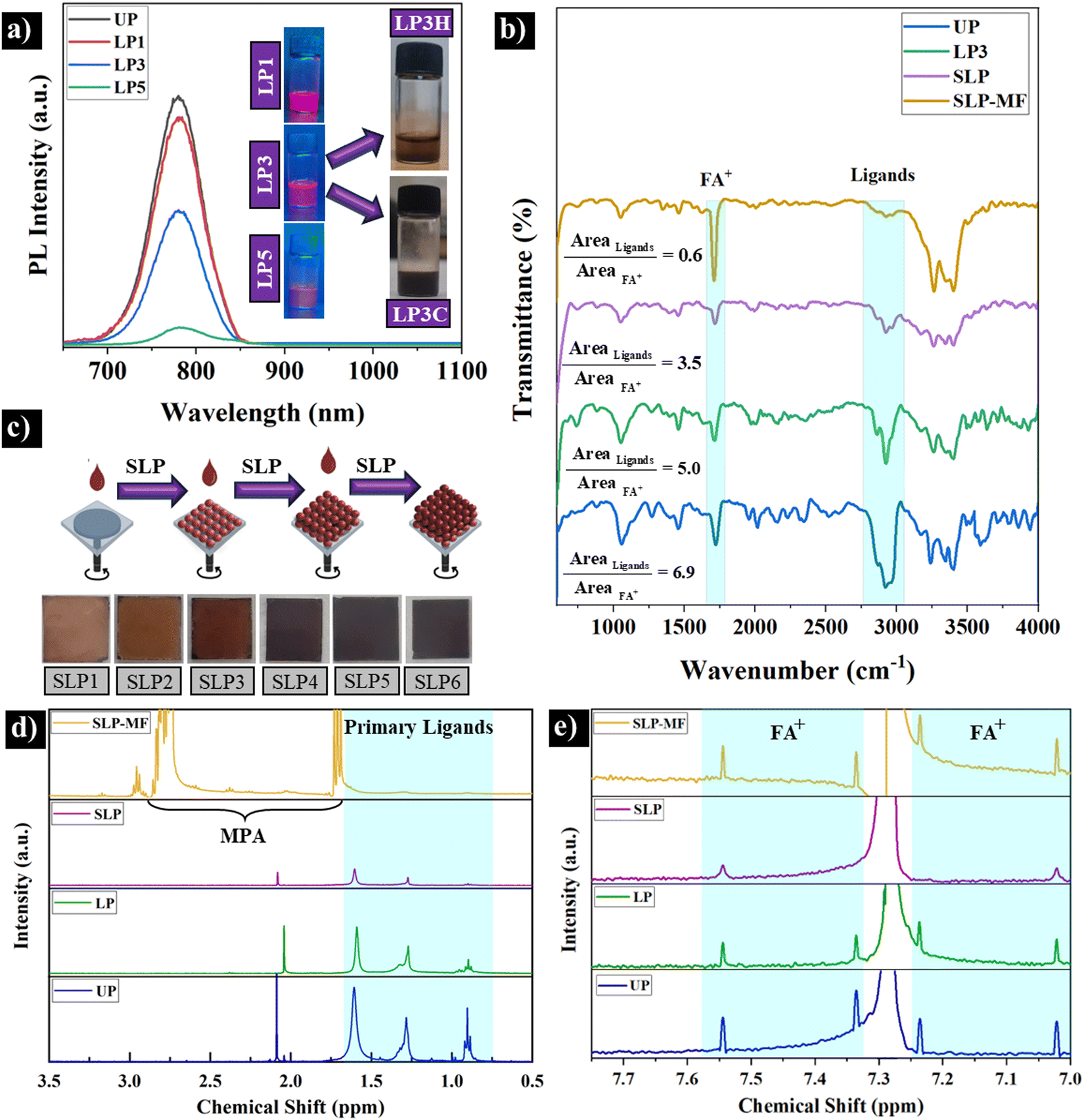 | ||
| Fig. 3 (a) Effect of liquid purification by MeOAc on the PL spectrum of FAPbI3 CQDs. LP1, LP3, and LP5 stand for 1, 3, and 5 mL MeOAc. The insert images show their emission under UV light. The colloidal stability after redispersion of LP3 QDs in hexane (LP3H) and chloroform (LP3C) is also shown. (b) ATR spectra of UP PQDs, liquid purified PQDs, spin-coat LP3C CQD films after solid-state purification (SLP) and ligand exchange with the MPA/FAI solution (SLP-MF). (c) The film-forming ability of LP3C CQDs after solid ligand purification by MeOAc for 1 to 6 runs (SLP1 to SLP6). (d) and (e) 1H NMR results from the same concentration of UP, LP3, SLP, and SLP-MF solutions. | ||
Solid-state purification and ligand exchange
To remove the remaining long-chain ligands and improve the film-forming ability of FAPbI3 CQDs, a solid ligand purification (SLP) procedure by MeOAc was applied layer-by-layer. After dropping 70 μL CQDs on the FTO substrate and spin coating, 70 μL of MeOAc was applied and spin coating was repeated for four times (Fig. 1d and 3(c)) to prepare a thicker layer of QDs. ATR spectra of the films determine significant decrease in the amount of the long-chain ligands (Fig. 3(b)). Using the same approach as liquid ligand purification, the ligand/FA+ ratio for the SLP sample is lower than that of UP and LP3 samples, indicating the capability of SLP in ligand removal. To analyze the SLP QDs by 1H NMR, a solution of SLP QDs with the same concentration as the UP and LP3 samples was prepared (see the Experimental section). As shown in Fig. 3(d) and Table S3 (ESI†), the integrated area of SLP QDs ligands peaks is 15.5%, showing that 84.49% of ligands was removed after liquid and solid purification processes. However, as shown in the next section, the SLP process leaves PQDs under-coordinated with many recombination sites. As a result, a relatively low PCE with large hysteresis is attained.Since trap passivation is critical, a robust ligand exchange process was implemented using spin-coating with short MPA and FAI ligands (see Fig. 1(d)). Fig. 3(b) highlights the intensification of peaks at 1717 cm−1 and in the 3000–3500 cm−1 range, which are attributed to FAIs present within and on the surface of the perovskite structure.43 The peaks in the 3000–3500 cm−1 range can be associated with the hydroxyl (O–H) stretching vibrations of MPA.44 Furthermore, the peaks at 1350 cm−1 and 1550 cm−1 may correspond to the symmetric and asymmetric stretching vibrations of the carboxylate groups in MPA, rather than those of OA, due to the absence of peaks in the 2800–3000 cm−1 region. Notably, the absence of a peak in the 2500–2600 cm−1 range, which corresponds to the S–H stretching vibration of MPA, indicates that the MPA ligand is bound to the QD surface via its thiolate group.45,46 Moreover, the ligand (primary long-chain ligand)/FA+ ratio for the SLP-MF sample is much lower than that of UP, LP3, and SLP samples, demonstrating the ligands removal probably due to both ligand purification and exchange processes. This was confirmed by 1H NMR test. The SLP-MF sample was prepared using the same procedure as the SLP sample. As shown in Fig. 3(d), the integrated area of the SLP-MF ligand peaks is only 2.6%, indicating that 97.4% of the ligands were removed. Moreover, different significant peaks between 1.5–3 ppm appeared. These peaks are related to MPA, confirming the presence of MPA on QDs’ surface.47,48 Regarding FA+ (small peaks between 7–8 ppm), the same integrated area of peaks approach was used. Fig. 3e and Table S3 (ESI†) show that by using liquid and solid purification processes, the percentage of FA+ decreases. Particularly, the SLP-MF sample demonstrates the effectiveness of our ligand exchange process, confirming the FTIR results. The reason behind the attachment as well as exchange of FA+ and MPA ligands with remaining primary long ligands can be explained as follows. In terms of the former, the ligands passivate the positively and negatively charged surface vacancies as well as undercoordinated surface atoms (Pb with MPA and I with FA+, Fig. 5(d and e)). Regarding the latter, the higher adsorption energy of shorter ligands than longer ligands is preferable for ligand exchange, confirmed by theoretical calculations in the literature.22,49
Device performance
The configuration of the designed n–i–p QD solar cell is illustrated in Fig. 4(a). Cross-sectional FESEM imaging reveals a laterally continuous FAPbI3 QD thin film (∼370 nm) with no visible micro-defects, sandwiched between SnO2 (∼35 nm) as the ETL and Spiro- OMeTAD (∼200 nm) as the HTL. Fig. 4(b) and Table 1 present the J–V curves of the SLP and SLP-MF champion cells with their corresponding performance metrics, measured under AM 1.5G illumination at 100 mW cm−2, using both forward and reverse scans. The average performance metrics of ten devices (n = 10) are summarized in Table S4 (ESI†), while the statistical distribution of photovoltaic parameters is shown in Fig. S3(a–d) (ESI†). | ||
| Fig. 4 (a) Schematic diagram and cross-section FESEM image of the configuration of the FAPbI3 QD solar cells. (b) Representative J–V curves of the processed devices. (c) EQE and the calculated integrated JSC curves of SLP and SLP-MF QD solar cells. | ||
| Cells | V OC (V) | J SC (mA cm−2) | FF (%) | PCE (%) |
|---|---|---|---|---|
| F-SLP | 1.08 | 11.10 | 54.88 | 6.58 |
| R-SLP | 1.08 | 11.99 | 68.3 | 8.85 |
| F-SLP-MF | 1.08 | 13.98 | 68.68 | 10.37 |
| R-SLP-MF | 1.09 | 14.12 | 73.2 | 11.26 |
The lower open-circuit voltage (VOC), short-circuit current density (JSC), fill factor (FF), and power conversion efficiency (PCE) observed in the forward scan compared to the reverse scan highlight the presence of hysteresis. This phenomenon is schematically explained in Fig. 5. The band alignment at the ETL/QD and QD/HTL interfaces induces a built-in voltage (or electric field), which causes the migration and accumulation of negatively charged FA vacancies and positively charged iodine vacancies at the ETL and HTL interfaces, respectively (Fig. 5(a)).50 This accumulation disconnects the PQD film from the ETL (or HTL), creating a secondary internal electric field that opposes the built-in voltage. Consequently, the solar cell's ability to separate electrons and holes is weakened. During the forward scan (FS), the applied voltage (e.g., V = 0.6VOC) is insufficient to evacuate defects from the interfaces, leading to reduced transfer of photogenerated carriers due to the abundance of trapping centers, which induce non-radiative recombination (Fig. 5(b)). Conversely, in the reverse scan (RS), the higher voltages (V > VOC) at the start of the measurement drive ion vacancies to migrate in opposite directions, thereby enhancing the built-in voltage, reducing interface trapping centers, and improving current density (Fig. 5(c)).
 | ||
| Fig. 5 Schematic diagrams showing the band structure of the perovskite solar cell (a) before measurement, (b) under forward scan (0 V–0.6VOC), and (c) under reverse scan (1.2 V–0.6VOC). (d) and (e) The effect of short ligand surface passivation on the tunneling probability and defect trapping. | ||
Following the solid ligand exchange with MPA and FAI (SLP-MF), two notable improvements were observed. Firstly, while the VOC showed a slight increase, significant enhancements were recorded in the JSC and FF, resulting in PCE of 11.3% in the reverse scan. Fig. S4 (ESI†) shows that the maximum PCE was achieved after four cycles of spin-coating and ligand exchange. The highest PCE was obtained when 100 μL MPA was used (Fig. S5, ESI†). The enhancement in JSC was further supported by the calculated JSC values derived from the external quantum efficiency (EQE), which revealed substantial improvements across a wide range of wavelengths, particularly above 500 nm (Fig. 4(c)), leading to the enhanced total integrated JSC of SLP-MF compared to SLP solar cells. Secondly, the SLP-MF solar cells exhibited a significantly reduced hysteresis compared to the SLP solar cells.
Photoluminescence and electrochemical impedance spectroscopy
To identify the main reason behind the performance improvement, PL and EIS measurements were conducted. Four samples were prepared by spin-coating of SLP and SLP-MF PQDs on borosilicate glass and FTO/SnO2 substrates. Compared to UP FAPbI3 CQDs, the PL peak and absorption edge wavelengths (Fig. S6, ESI†) of PQD thin films exhibited a 20 nm redshift, likely due to reduced interparticle spacing in PQDs and enhanced electronic coupling within the thin film, diminishing molecular-like behavior.51,52 However, it's still lower than the absorption edge of the bulk FAPbI3 (>820 nm), confirming the presence of QDs. As shown in Fig. 6(a), SLP PQDs on the glass demonstrated PL emission, attributed to the presence of a small fraction of residual ligands and the absence of band bending between the SLP and the insulating substrate, which promotes radiative recombination. In contrast, the emission intensity of SLP PQDs on FTO/SnO2 was reduced by nearly half, which can be attributed to enhanced electron transfer facilitated by the band bending formed between SnO2 and PQDs.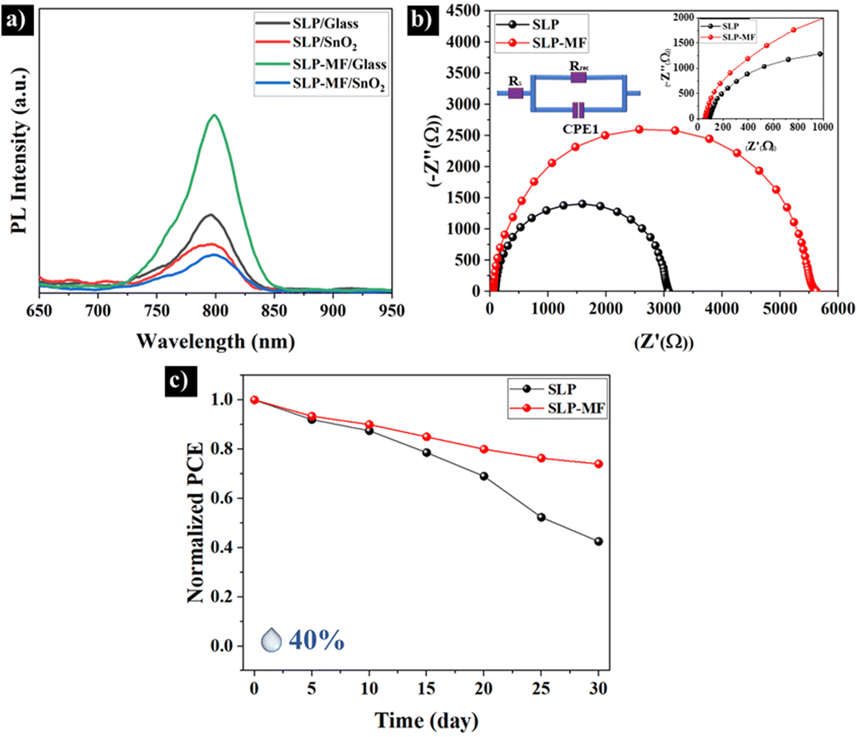 | ||
| Fig. 6 (a) PL spectra of SLP and SLP-MF QDs coated on FTO/SnO2 and borosilicate glass substrates. (b) EIS of SLP and SLP-MF QD-based solar cells. (c) PCE stability of SLP and SLP-MF QD solar cells for a month. | ||
Compared to SLP PQDs, spin-coated SLP-MF PQDs on the glass exhibited stronger PL emission, highlighting the superior ability of MPA and FAI to passivate surface vacancy defects and dangling bonds. This led to a significant reduction in Shockley–Read–Hall (SRH) recombination centers and enhanced radiative recombination.53 The short-chain ligands (MPA and FAI) are particularly effective at passivating higher concentrations of surface atoms due to their reduced steric hindrance.54 Notably, the PL intensity of SLP-MF PQDs on FTO/SnO2 exhibits a significant reduction compared to SLP PQDs, indicating improved charge separation. This improvement is attributed to the replacement of the longer oleate and ammonium ligands with the shorter MPA and FAI ligands. The shorter ligands reduce interdot distances and enhance the probability of electron and hole tunneling between PQDs in the thin film and at their interfaces with the HTL and ETL, as depicted in Fig. 1(d) and Fig. 5(d and e). Interestingly, as observed in Fig. S7(a and b) (ESI†), the SLP-MF sample exhibits a significantly lower amounts of voids and agglomerations, along with a more uniform surface. This highlights the effectiveness of the ligand exchange process in improving thin-film formation and performance of solar cells.
Fig. 6(b) shows the results of EIS. This series resistance (Rs) and the charge recombination resistance (Rrec) calculated from the large semicircle curve of SLP QDs are 88.9 Ω and 3041 Ω, respectively. The results determine that Rs for the SLP-MF PQDs (55.3 Ω) is lower than that of SLP PQDs. However, the Rrec of the surface modified solar cell (5556 Ω) is significantly enhanced, showing the suppressed recombination, higher conductivity, and improved charge transportation of SLP-MF solar cells.55–57 As a result, enhanced current density has been achieved after solid-ligand surface modification.
To evaluate the stability of the cells, the PCE of the devices stored under ambient air conditions (average humidity = 40%) at room temperature was measured over 30 days. Fig. 6(c) presents the normalized PCE of the cells as a function of time. The SLP cells retained only 40% of their initial PCE, whereas the normalized PCE of the SLP-MF PQDs remained above 75%. This result highlights the effectiveness of MPA and FAI in passivating surface defects of QDs, formed during liquid/solid purification, thereby enhancing their resistance to degradation.
Conclusions
In summary, we successfully prepared a stable colloidal solution of FAPbI3 perovskite quantum dots (PQDs) using a modified ligand-assisted reprecipitation method. High-resolution TEM (HRTEM) confirmed the synthesis of FAPbI3 PQDs with an average size of ∼11 nm. XRD and spectroscopic analyses revealed the formation of highly fluorescent PQDs in the α-phase. Additionally, long-chain ligands purification was achieved through liquid and solid purification processes using MeOAc. Apart from FTIR results, 1H NMR could reveal that remaining surface ligands after liquid and solid purification are ∼48% and ∼15.5%, respectively. Moreover, 1H NMR results showed the presence of MPA and intensification of FA+ after solid ligand exchange, confirming the passivation of under-coordinated atoms with short-chain ligands using direct attachment or ligand exchange processes. This modification led to hysteresis reduction as well as significant improvements in photovoltaic performance metrics: the JSC, FF, and PCE increased from 11.99 mA cm−2, 68.3%, and 8.8% to 14.12 mA cm−2, 73.2%, and 11.3%, respectively. The stability of the cells was also remarkably enhanced. EIS measurements showed that surface modification increased the charge recombination resistance and reduced the series resistance, demonstrating the effectiveness of MPA and FAI in passivating surface defects and reducing interdot distances. This modification provides valuable insights for advancing the next generation of efficient and stable PQD-based devices.Author contributions
M. H. A. and H. A. designed experiments, synthesized and purified QDs, fabricated the PSCs devices, carried out electrical measurements, analysed data, and wrote and edited the manuscript. S. A. did some experiments, analysed samples, and edited the manuscript. A. S. supervised the work and provided funding. All authors reviewed the manuscript.Data availability
The data supporting this article have been included as part of the ESI.†Conflicts of interest
There are no conflicts to declare.Acknowledgements
Simchi acknowledges the Alexander von Humboldt Foundation for the Georg Förster Research award.References
- L. Yuan, S. Zou, K. Zhang, P. Huang, Y. Dong, J. Wang, K. Fan, M. Y. Lam, X. Wu, W. Cheng, R. Tang, W. Chen, W. Liu, K. S. Wong and K. Yan, Adv. Mater., 2024, 36, 2409261 CrossRef CAS PubMed
.
- M. Hasanzadeh Azar, S. Aynehband, H. Abdollahi, H. Alimohammadi, N. Rajabi, S. Angizi, V. Kamraninejad, R. Teimouri, R. Mohammadpour and A. Simchi, Photonics, 2023, 10, 271 CrossRef CAS
- S. Chandra, M. A. Mustafa, K. Ghadir, P. Bansal, M. Deorari, D. Y. Alhameedi, M. H. Shuhata Alubiady, A. M. Al-Ani, S. O. Rab, S. S. Jumaa and M. K. Abosaoda, Naunyn-Schmiedeberg's Arch. Pharmacol., 2024, 397, 10223 CrossRef CAS PubMed
- J. Xue, J. W. Lee, Z. Dai, R. Wang, S. Nuryyeva, M. E. Liao, S. Y. Chang, L. Meng, D. Meng, P. Sun, O. Lin, M. S. Goorsky and Y. Yang, Joule, 2018, 2, 1866–1878 CrossRef CAS
- H. Goodwin, T. C. Jellicoe, N. J. L. K. Davis and M. L. Böhm, Nanophotonics, 2018, 7, 111–126 CrossRef
- L. Liu, A. Najar, K. Wang, M. Du and S. Liu, Adv. Sci., 2022, 9, 2104577 CrossRef CAS PubMed
- M. Hao, S. Ding, S. Gaznaghi, H. Cheng and L. Wang, ACS Energy Lett., 2024, 9, 308–322 CrossRef CAS
- B. Alessi and V. Svrcek, Sol. RRL, 2024, 8, 2400379 CrossRef CAS
- H. Li, H. Huang, D. Li, X. Zhang, C. Zhao, X. Zhao, W. Ma and J. Yuan, Energy Environ. Sci., 2025, 18, 972–981 RSC
- S. Pitchaiya, M. Natarajan, A. Santhanam, V. Asokan, A. Yuvapragasam, V. Madurai Ramakrishnan, S. E. Palanisamy, S. Sundaram and D. Velauthapillai, Arabian J. Chem., 2020, 13, 2526–2557 CrossRef CAS
- X. Zhang, H. Huang, C. Zhao, L. Jin, C. Lee, Y. Li, D. H. Ko, W. Ma, T. Wu and J. Yuan, Nat. Energy, 2024, 9, 1378–1387 CrossRef CAS
- G. A. Nowsherwan, Q. Ali, N. Nowsherwan, U. F. Ali and S. S. Hussain, Multiscale and Multidisciplinary Modeling, Exp. Des., 2025, 8, 1–20 Search PubMed
- C. Zhao, X. Zhao, H. Huang, X. Zhang and J. Yuan, Chem. Commun., 2024, 60, 9214–9217 RSC
- M. Hiraishi, A. Koda, H. Okabe, R. Kadono, K. A. Dagnall, J. J. Choi and S. H. Lee, J. Appl. Phys., 2023, 134, 1–7 CrossRef
- M. H. Li, F. Z. Qiu, S. Wang, Y. Jiang and J. S. Hu, Mater. Today, 2022, 52, 250–268 CrossRef CAS
- X. Ling, J. Yuan and W. Ma, Acc. Mater. Res., 2022, 3, 866–878 CrossRef CAS
- J. Xue, R. Wang, L. Chen, S. Nuryyeva, T. H. Han, T. Huang, S. Tan, J. Zhu, M. Wang, Z. K. Wang, C. Zhang, J. W. Lee and Y. Yang, Adv. Mater., 2019, 31, 1900111 CrossRef PubMed
- S. M. H. Qaid, H. M. Ghaithan, B. A. Al-Asbahi and A. S. Aldwayyan, Surf. Interfaces, 2021, 23, 100948 CrossRef CAS
- R. An, F. Zhang, X. Zou, Y. Tang, M. Liang, I. Oshchapovskyy, Y. Liu, A. Honarfar, Y. Zhong, C. Li, H. Geng, J. Chen, S. E. Canton, T. Pullerits and K. Zheng, ACS Appl. Mater. Interfaces, 2018, 10, 39222–39227 CrossRef CAS PubMed
- D. Jia, J. Chen, J. Qiu, H. Ma, M. Yu, J. Liu and X. Zhang, Joule, 2022, 6, 1632–1653 CrossRef CAS
- L. M. Wheeler, E. M. Sanehira, A. R. Marshall, P. Schulz, M. Suri, N. C. Anderson, J. A. Christians, D. Nordlund, D. Sokaras, T. Kroll, S. P. Harvey, J. J. Berry, L. Y. Lin and J. M. Luther, J. Am. Chem. Soc., 2018, 140, 10504–10513 CrossRef CAS PubMed
- K. Chen, Q. Zhong, W. Chen, B. Sang, Y. Wang, T. Yang, Y. Liu, Y. Zhang and H. Zhang, Adv. Funct. Mater., 2019, 29, 1900991 CrossRef
- H. S. Yang, E. H. Suh, S. H. Noh, J. Jung, J. G. Oh, K. H. Lee, D. Lee and J. Jang, Chem. Eng. J., 2023, 454, 140331 CrossRef CAS
- M. Kim, D. Cortecchia, T. Borzda, W. Mróz, L. Leoncino, D. Dellasega, S. H. Lee and A. Petrozza, Chem. Mater., 2021, 33, 547–553 CrossRef CAS
- A. Jancik Prochazkova, M. C. Scharber, C. Yumusak, J. Jančík, J. Másilko, O. Brüggemann, M. Weiter, N. S. Sariciftci, J. Krajcovic, Y. Salinas and A. Kovalenko, Sci. Rep., 2020, 10, 15720 CrossRef CAS PubMed
- J. H. Song, H. Choi, H. T. Pham and S. Jeong, Nat. Commun., 2018, 9, 4267 CrossRef PubMed
- M. Gu, Y. Wang, F. Yang, K. Lu, Y. Xue, T. Wu, H. Fang, S. Zhou, Y. Zhang, X. Ling, Y. Xu, F. Li, J. Yuan, M. A. Loi, Z. Liu and W. Ma, J. Mater. Chem. A, 2019, 7, 15951–15959 RSC
- H. Beygi, S. A. Sajjadi, A. Babakhani, J. F. Young and F. C. J. M. van Veggel, Appl. Surf. Sci., 2018, 459, 562–571 CrossRef CAS
- M. Hasanzadeh Azar, M. Mohammadi, N. T. Rezaei, S. Aynehband, L. Shooshtari, R. Mohammadpour and A. Simchi, ACS Appl. Nano Mater., 2021, 4, 7788–7799 CrossRef CAS
- H. Azar, M. Mohammadi, N. T. Rezaei, S. Aynehband and A. Simchi, J. Alloys Compd., 2022, 907, 164465 CrossRef
- F. Zhang, S. Huang, P. Wang, X. Chen, S. Zhao, Y. Dong and H. Zhong, Chem. Mater., 2017, 29, 3793–3799 CrossRef CAS
- C. Müller, T. Glaser, M. Plogmeyer, M. Sendner, S. Döring, A. A. Bakulin, C. Brzuska, R. Scheer, M. S. Pshenichnikov, W. Kowalsky, A. Pucci and R. Lovrinčić, Chem. Mater., 2015, 27, 7835–7841 CrossRef
- Y. Gao, D. Lin, P. Liu, T. Shi and W. Xie, Mater. Chem. Front., 2024, 8, 785–799 RSC
- S. Porwal, N. K. Bansal, S. Ghosh and T. Singh, Energy Adv., 2024, 3, 894–903 RSC
- G. Murugadoss, P. Arunachalam, S. K. Panda, M. Rajesh Kumar, J. R. Rajabathar, H. Al-Lohedan and M. D. Wasmiah, J. Mater. Res. Technol., 2021, 12, 1924–1930 CrossRef CAS
- I. Levchuk, A. Osvet, X. Tang, M. Brandl, J. D. Perea, F. Hoegl, G. J. Matt, R. Hock, M. Batentschuk and C. J. Brabec, Nano Lett., 2017, 17, 2765–2770 CrossRef CAS PubMed
- R. Liu, C. Deng, G. Li, Y. Tu, G. Yang, H. Chen, J. Song, Q. Zhou, Y. Zang, L. Weng, L. Chu, J. Wu and W. Yan, Chem. Eng. J., 2024, 502, 157734 CrossRef CAS
- R. Wang, J. Ni, J. Guan, S. Zhang, M. Yan, S. Li, Y. Zhang, J. Li, H. Cai and J. Zhang, ACS Sustainable Chem. Eng., 2024, 12, 14514–14523 CrossRef CAS
- S. Ding, M. Hao, C. Fu, T. Lin, A. Baktash, P. Chen, D. He, C. Zhang, W. Chen, A. K. Whittaker, Y. Bai and L. Wang, Adv. Sci., 2022, 9, 2204476 CrossRef CAS PubMed
- A. Maulu, P. J. Rodríguez-Cantó, J. Navarro-Arenas, R. Abargues, J. F. Sánchez-Royo, R. García-Calzada and J. P. Martínez Pastor, RSC Adv., 2016, 6, 80201–80212 RSC
- Z. L. Teh, L. Hu, Z. Zhang, A. R. Gentle, Z. Chen, Y. Gao, L. Yuan, Y. Hu, T. Wu, R. J. Patterson and S. Huang, ACS Appl. Mater. Interfaces, 2020, 12, 22751–22759 CrossRef CAS PubMed
- J. Kim, S. Han, G. Lee, J. Choi, M. Jae Ko and Y. Kim, Chem. Eng. J., 2022, 448, 137672 CrossRef CAS
- S. R. Ankireddy and J. Kim, Int. J. Nanomed., 2015, 10, 121–128 CAS
- J. Han, C. McBean, L. Wang, J. Hoy, C. Jaye, H. Liu, Z. Q. Li, M. Y. Sfeir, D. A. Fischer, G. T. Taylor, J. A. Misewich and S. S. Wong, Chem. Mater., 2015, 27, 778–792 CrossRef CAS
- N. T. Vo, H. D. Ngo, D. L. Vu, A. P. Duong and Q. V. Lam, J. Nanomater., 2015, 2015, 1–7 Search PubMed
- A. G. Pattantyus-Abraham, I. J. Kramer, A. R. Barkhouse, X. Wang, G. Konstantatos, R. Debnath, L. Levina, I. Raabe, M. K. Nazeeruddin, M. Grätzel and E. H. Sargent, ACS Nano, 2010, 4, 3374–3380 CrossRef CAS PubMed
- J. Kang, J. P. Richardson and D. MacMillan, Chem. Commun., 2009, 407–409 RSC
- B. Schuetze, C. Mayer, K. Loza, M. Gocyla, M. Heggen and M. Epple, J. Mater. Chem. B, 2016, 4, 2179–2189 RSC
- B. Qi and J. Wang, J. Mater. Chem., 2012, 22, 24315–24325 RSC
- P. Calado, A. M. Telford, D. Bryant, X. Li, J. Nelson, B. C. O’Regan and P. R. F. Barnes, Nat. Commun., 2016, 7, 13831 CrossRef CAS PubMed
- X. Ling, S. Zhou, J. Yuan, J. Shi, Y. Qian, B. W. Larson, Q. Zhao, C. Qin, F. Li, G. Shi, C. Stewart, J. Hu, X. Zhang, J. M. Luther, S. Duhm and W. Ma, Adv. Energy Mater., 2019, 9, 1900721 CrossRef
- E. M. Sanehira, A. R. Marshall, J. A. Christians, S. P. Harvey, P. N. Ciesielski, L. M. Wheeler, P. Schulz, L. Y. Lin, M. C. Beard and J. M. Luther, Sci. Adv., 2017, 3, 1–8 Search PubMed
- V. Sarritzu, N. Sestu, D. Marongiu, X. Chang, S. Masi, A. Rizzo, S. Colella, F. Quochi, M. Saba, A. Mura and G. Bongiovanni, Sci. Rep., 2017, 7, 44629 CrossRef CAS PubMed
- S. Yang, J. Li, J. Wang, L. Zhang, L. Fan, X. Chen, F. Huang and J. Tian, Chem. Eng. J., 2024, 488, 150799 CrossRef CAS
- S. Khanmohammadi, K. Kushnir Friedman, E. Chen, S. M. Kastuar, C. E. Ekuma, K. J. Koski and L. V. Titova, ACS Appl. Mater. Interfaces, 2024, 16, 16445–16452 CrossRef CAS PubMed
- S. B. Shivarudraiah, M. Ng, C. H. A. Li and J. E. Halpert, ACS Appl. Energy Mater., 2020, 3, 5620–5627 CrossRef CAS
- K. Chen, W. Jin, Y. Zhang, T. Yang, P. Reiss, Q. Zhong, U. Bach, Q. Li, Y. Wang, H. Zhang, Q. Bao and Y. Liu, J. Am. Chem. Soc., 2020, 142, 3775–3783 CrossRef CAS PubMed
Footnotes |
| † Electronic supplementary information (ESI) available. See DOI: https://doi.org/10.1039/d5tc00040h |
| ‡ These two authors contributed equally. |
| This journal is © The Royal Society of Chemistry 2025 |