
Enhanced three-photon absorption excited at near-infrared laser pulses and stability of MAPbBr3 quantum dots encapsulated in mesoporous single MOF-5 crystals†
Wenqing
Wang‡
a,
Renhua
Liu‡
b,
Shaowen
Zhu
a,
Minjie
Zhou
c,
Bing
Jin
d,
Shunbin
Lu
*b,
Min
Liu
 *a,
Xuantao
Su
*a and
Wei
Ji
be
*a,
Xuantao
Su
*a and
Wei
Ji
be
aSchool of Integrated Circuits, Shandong University, Jinan 250100, China. E-mail: xtsu@sdu.edu.cn; liumin@sdu.edu.cn
bInternational Collaborative Laboratory of 2D Materials for Optoelectronic Science & Technology of Ministry of Education, Institute of Microscale Optoelectronics (IMO), Shenzhen University, Shenzhen 518060, China. E-mail: shunbin_lu@szu.edu.cn
cCenter for Optics and Research Engineer, Key Laboratory of Laser and Infrared System, Ministry of Education, Shandong University, Qingdao 266237, China
dInstitute of Frontier Chemistry, School of Chemistry and Chemical Engineering, Shandong University, Qingdao 266237, China
eDepartment of Physics, National University of Singapore, Singapore 117551, Singapore
First published on 23rd January 2025
Abstract
Organometallic halide perovskites have attracted attention due to their excellent optical properties. However, the inherent instability limits their wide application in the field of optoelectronics. In this study, a distribution immersion method was used to embed MAPbBr3 perovskite quantum dots into mesoporous MOF-5 microcrystals, constructing an effective host–guest structure. Compared with MAPbBr3 quantum dots, the MAPbBr3@MOF-5 composite not only exhibits superior optical performance but also significantly enhanced long-term stability and thermal stability. Nonlinear optical analysis shows that under the excitation of near-infrared femtosecond laser pulses, the MAPbBr3@MOF-5 composite exhibits significantly enhanced multiphoton absorption capability. Notably, its effective three-photon absorption coefficient (α3η ≈ (27.4 ± 3.1) × 10−5 cm3 GW−2) is an order of magnitude larger than that of MAPbBr3. These outstanding characteristics indicate that the MAPbBr3@MOF-5 composite has great potential for applications in photonics and information communication, especially in the manufacture of multifunctional nonlinear optical devices and future micro–nano photonic integration technologies.
Introduction
Hybrid organic–inorganic halide perovskite materials, such as MAPbX3 (X = Cl, Br, I), have garnered significant attention due to their potential applications in various fields. These materials exhibit exceptional optoelectronic properties, making them highly promising for use in solar cells, light-emitting diodes (LEDs), lasers, photodetectors, and multifunctional sensors.1–5 Recently, colloidal perovskite MAPbX3 nanocrystals (NCs), also known as quantum dots (QDs), have been attracting attention due to their excellent luminescent properties, which include high photoluminescence (PL) quantum yields, tunable emission wavelengths, short-radiative lifetimes, and narrow-band emissions.6–8 In addition to excellent linear optical properties, MAPbX3 NCs also exhibit remarkable nonlinear optical (NLO) responses.9,10 Among them, multi-photon excited photoluminescence (MPEPL) is particularly prominent. MPEPL involves the absorption of multiple photons, causing an electron to jump from the ground state to the excited state while leaving a hole in the ground state. Subsequently, the electron relaxes to the lowest energy level of the excited state and radiatively recombines with the hole in the ground state. MPEPL has a wide range of applications in the fields of optoelectronics, transmission of photonic signals and biomedicine.11,12 However, although MAPbX3 exhibits excellent performance, its practical applications are limited by the instability of organic cations, which are prone to rapid degradation under conditions such as moisture, UV radiation, oxygen and high temperature.13 Therefore, an improvement in the stability of perovskite quantum dots is a key challenge in realizing their optical applications. One feasible solution is to design and fabricate hybrid composite materials incorporating perovskite QDs.Metal–organic frameworks (MOFs) are a class of porous crystalline materials with fascinating properties, including tunable pore sizes and high specific surface areas. These characteristics make them promising platforms for host–guest chemistry.14–16 MOFs can be conveniently designed and self-assembled to provide ideal host environments for various guest species.17–19 MOF-5 (C24H12O13Zn4) features a three-dimensional structure and is characterized by its high specific surface area, significant porosity, and exceptional thermal stability.20 In comparison to MOFs with one- or two-dimensional structures, such as MOF-8,21 which is defined by its one-dimensional chain structure, MOF-5 offers a more comprehensive platform for exploring the influence of pore size on doped quantum dots and was therefore selected for this study. There have been reports of integrating various QDs into MOFs to develop novel composite materials with superior combined properties compared to their individual components.22 Although there have been studies on loading perovskite MAPbX3 QDs into different hosts to enhance their stability, a more extensive exploration for improving the stability of these materials is still needed.15,23,24 The fundamental properties, mechanisms, and nonlinear optical characteristics of MAPbX3 QDs encapsulated in MOFs remain relatively unexplored.
Here, we report a stepwise impregnation method to embed perovskite MAPbBr3 QDs into mesoporous MOF-5 single crystals. Compared to MAPbBr3 QDs, the resulting MAPbBr3@MOF-5 composite materials exhibited improved long-term storage stability and high thermal stability. Moreover, we found that the three-photon absorption coefficient of MAPbBr3@MOF-5 was significantly enhanced compared to MAPbBr3 microcrystals.25,26 This enhancement is attributed to the strong confinement and surface passivation provided by the MOF-5 framework.
Experimental section
The preparation process of the MAPbBr3@MOF-5 composite is shown in Scheme 1, which includes three steps: (a) synthesis of mesoporous MOF-5 microcrystals by a solvothermal method, (b) introduction of Pb2+ into the pores of MOF-5 by an immersion method, and (c) addition of Pb2+@MOF-5 to MABr solution to facilitate the formation of perovskite quantum dots within the pores of MOF-5. | ||
| Scheme 1 Synthesis process of MAPbBr3@MOF-5. | ||
The structure of MAPbBr3@MOF-5 was characterized by scanning electron microscopy (SEM), powder X-ray diffraction (XRD), and transmission electron microscopy (TEM). To test the thermal stability, thermogravimetric analysis (TGA) was performed on MAPbBr3@MOF-5. Additionally, PL, time-resolved PL, and absorption spectra were measured.
Detailed information on the materials and chemicals used, synthesis of MOF-5, MAPbBr3, and the MAPbBr3@MOF-5 composite, detection methodology, and instrumental techniques can be found in the ESI.†
Results and discussion
MOF-5 is an excellent metal–organic framework material composed of PTA and tetrahedral ZnO4 units, featuring high porosity and good stability. The microporous MOF-5 is synthesized by dissolving Zn(NO3)2·6H2O and PTA in a DMF solution and heating at 135 °C for 24 hours. Its micropore sizes are about 1.85 nm,27 which limits the encapsulation of MAPbBr3 into MOF-5. Therefore, in order to obtain mesoporous MOF-5 crystals, CTAB and TMB were used as templating agents in this work to expand the porosity of the MOF-5 microcrystals. CTAB occupies the pore channels of the MOF-5 microcrystals, and TMB further expands the pore channel sizes by swelling CTAB micelles, thereby increasing the pore sizes of the MOF-5 microcrystals.20,28 By changing the molar ratios of the reactants, we synthesized a series of MOF-5 microcrystals and studied the changes in PL intensity of MAPbBr3 encapsulated in MOF-5 microcrystals synthesized with different reactant molar ratios (Fig. S1, ESI†). When the molar ratio is 1![[thin space (1/6-em)]](https://www.rsc.org/images/entities/char_2009.gif) :2 for CTAB to TMB, the PL intensity of the hybrid material is the strongest compared to other ratios after encapsulating MAPbBr3 QDs. This may be attributed to the fact that MOF-5 synthesized using this molar ratio has the highest mesoporous porosity and the most suitable mesoporous pore size. The introduction of CTAB can expand the mesoporous volume of MOF-5, but this expansion is limited. Then, using TMB to swell CTAB micelles can significantly increase the pore volume. However, excessive addition of TMB may damage the porous structure of the MOF-5 crystals.20 Therefore, there is an optimal molar ratio to achieve the best encapsulation of MAPbBr3 QDs. Further confirmation of the effect of CTAB and TMB addition on the pore expansion of the MOF-5 samples was achieved through characterization by XRD and SEM. As shown in Fig. S2 (ESI†), the XRD pattern of the treated MOF-5 sample deviates from that of the theoretical MOF-5 and some impurity peaks can be observed. This may be attributed to the increase in pore size of the treated MOF-5, which consequently leads to changes in its crystal structure, including the introduction of defects (Fig. S2(a), ESI†).20 After CTAB is embedded, the MOF particles maintain their cubic morphology, but larger cavities are observed within the particles (Fig. S2(b), ESI†), indicating effective expansion of the internal pore structure.
:2 for CTAB to TMB, the PL intensity of the hybrid material is the strongest compared to other ratios after encapsulating MAPbBr3 QDs. This may be attributed to the fact that MOF-5 synthesized using this molar ratio has the highest mesoporous porosity and the most suitable mesoporous pore size. The introduction of CTAB can expand the mesoporous volume of MOF-5, but this expansion is limited. Then, using TMB to swell CTAB micelles can significantly increase the pore volume. However, excessive addition of TMB may damage the porous structure of the MOF-5 crystals.20 Therefore, there is an optimal molar ratio to achieve the best encapsulation of MAPbBr3 QDs. Further confirmation of the effect of CTAB and TMB addition on the pore expansion of the MOF-5 samples was achieved through characterization by XRD and SEM. As shown in Fig. S2 (ESI†), the XRD pattern of the treated MOF-5 sample deviates from that of the theoretical MOF-5 and some impurity peaks can be observed. This may be attributed to the increase in pore size of the treated MOF-5, which consequently leads to changes in its crystal structure, including the introduction of defects (Fig. S2(a), ESI†).20 After CTAB is embedded, the MOF particles maintain their cubic morphology, but larger cavities are observed within the particles (Fig. S2(b), ESI†), indicating effective expansion of the internal pore structure.
In Fig. 1(a), the XRD pattern of MAPbBr3@MOF-5 is shown. Both the XRD peaks of MOF-5 and MAPbBr3 in the XRD pattern of MAPbBr3@MOF-5 were observed. After embedding QDs, MAPbBr3@MOF-5 demonstrated peaks of 14.82°, 30.00°, 33.64° and 43.06° corresponding to the planes of (010), (200), (210) and (202) of MAPbBr3, respectively. The TEM image (Fig. 1(b)) shows that the PeQDs are embedded in the holes of MOF-5. Based on the size distribution histogram and Gauss fitting of MAPbBr3 QDs (Fig. 1(c)), the average size of the QD particles is 12 nm. The average size of the QDs in other regions, as determined from the TEM results, is shown in Fig. S2(c–f) (ESI†). The HRTEM images are shown in Fig. 1(d and e). The interplanar distance from the fringes is 2.96 Å, which could be attributed to the (200) planes of the MAPbBr3. The SEM mapping images, as shown in Fig. 1(f), show the uniform distribution of the four elements, indicating the coexistence of the MAPbBr3 QDs and MOF-5. The inset of Fig. S2(b) (ESI†) displays an image of the MAPbBr3@MOF-5 sample. Fig. S3 (ESI†) depicts the TGA analysis of MAPbBr3@MOF-5, showing that when heated to 400 °C in a nitrogen atmosphere, the composite material experiences a mass loss of only 12.1%. The result indicates that MAPbBr3@MOF-5 demonstrates good thermal stability and possesses a high decomposition temperature.
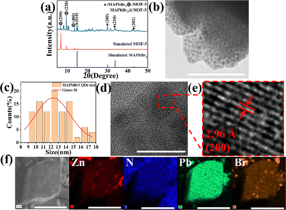 | ||
| Fig. 1 Structure characterization. (a) XRD patterns of MAPbBr3@MOF-5. (b) TEM (scale bar: 100 nm) and (c) histogram of MAPbBr3 particle size distribution with Gauss fitting. (d) and (e) HRTEM of MAPbBr3@MOF-5 (scale bar, 20 nm). (f) SEM mapping of elements (Zn, N, Pb and Br) in MAPbBr3@MOF-5 (scale bar, 20 μm). | ||
The fluorescence properties of the synthesized MAPbBr3@MOF-5 composite were subsequently analyzed. The PL spectra of MAPbBr3 and MAPbBr3@MOF-5 are shown in Fig. 2(a). After embedding QDs into MOF-5, the MAPbBr3@MOF-5 composite exhibits a narrow green peak centered at 533 nm under UV excitation (375 nm). The narrow green peak of MAPbBr3@MOF-5 can be attributed to the emission of MAPbBr3 QDs. Compared to MAPbBr3, the PL peak wavelength of MAPbBr3 QDs in the MAPbBr3@MOF-5 composite has a blue shift of 20 nm. The absorption spectra in Fig. 2(b) also show a blue shift in the absorption edges of MAPbBr3@MOF-5 compared to MAPbBr3 (more details can be found in the section titled ‘Characterization’ in ESI†). These properties can be attributed to the strong quantum confinement effect of perovskite QDs. When the size of metal halide perovskite QDs is reduced to the nanometer scale, the electronic band structure of the perovskite undergoes changes. Due to the quantum confinement effect, the emission peak shifts from green to blue.29,30 The PL decay curves of MAPbBr3@MOF-5 and MAPbBr3 monitored at 533 nm under UV light (375 nm) excitation are shown in Fig. 2(c). The PL decay of MAPbBr3@MOF-5 can be described by a bi-exponential fit.31 The average fluorescence lifetime of MAPbBr3 increased from 2.4 ns to 28.5 ns for MAPbBr3@MOF-5. Fig. S4(a) (ESI†) illustrates the variation of the photoluminescence (PL) lifetime within the temperature range from 300 to 430 K and the derived lifetime decreases from 43.6 ns to 5.5 ns, as shown in Fig. S4(b) (ESI†).32,33 As the temperature increases, the thermal excitation drives the lattice structure to undergo distortion. Simultaneously, the generation of thermal defects initiates a pronounced non-radiative recombination process.34 The non-radiative decay rate of MAPbBr3@MOF-5 rises with increasing temperature. This elevated non-radiative decay rate results in a significant reduction in the PL lifetime. It is well-known that the PL decay of perovskite materials is often attributed to radiative and non-radiative recombination processes of excitons, with non-radiative recombination typically associated with short lifetimes in the lifetime fitting.35 The extended lifetime may be attributed to surface passivation, which reduces the nonradiative relaxation of surface traps in encapsulated MAPbBr3 QDs.36–38 Additionally, there is significant spectral overlap between the emission of MOF-5 crystals and the absorption of MAPbBr3 QDs. Therefore, energy transfer from MOF-5 crystals to MAPbBr3 QDs is expected to occur in MAPbBr3@MOF-5.39 Moreover, by adjusting the concentration of MABr, we can manipulate the emission of MAPbBr3@MOF-5. Fig. 2(d) displays a series of PL spectra for MAPbBr3@MOF-5, showing that as the concentration of MABr increases (0.5, 1, 1.5, 2, 2.5 mg mL−1), the PL intensity at first increases and then decreases, reaching a maximum at a concentration of 1.5 mg mL−1. As the concentration of MABr increases, the amount of MAPbBr3 QDs in the MAPbBr3@MOF-5 composite rises, leading to a proportional enhancement of the composite's photoluminescence (PL) intensity. However, if the amount of MABr added exceeds a certain threshold, quantum dots aggregation may occur, resulting in a reduction in PL intensity.
 | ||
| Fig. 2 (a) The normalized PL spectra, (b) the UV-Vis absorption, (c) the PL decay plots of MAPbBr3@MOF-5 and MAPbBr3 and (d) the PL spectra of MAPbBr3@MOF-5 synthesized with varying concentrations of MABr. | ||
Notably, we have observed a substantial improvement in the stability of the MAPbBr3@MOF-5 composite material. We performed thermal stability tests and long-term stability tests on the composite material and compared the results with those of MAPbBr3 powder. As shown in Fig. 3(a), MAPbBr3@MOF-5 maintained 49.3% of its original photoluminescence (PL) intensity at 55 °C, and even still emitted light at 125 °C. After 90 days of exposure to air at room temperature, MAPbBr3@MOF-5 retained 63.9% of its initial PL intensity, whereas the MAPbBr3 QDs showed complete quenching after 14 days (Fig. 3(b)). Based on these results, we can conclude that the MAPbBr3@MOF-5 composite is significantly more stable in air and at high temperatures compared to MAPbBr3 PeQDs.
 | ||
| Fig. 3 Thermal stability test (a) and long-term storage stability test (b) of MAPbBr3@MOF-5. Insets: Normalized PL intensity as a function of experimental temperature (a) and storage time (b) for MAPbBr3@MOF-5 (red line) and MAPbBr3 (black line). | ||
Under excitation by near-infrared femtosecond laser pulses, MAPbBr3@MOF-5 demonstrates excellent MPEPL (more experimental details can be found in the section titled ‘Multi-photon excited photoluminescence’ in the ESI†). Fig. S5 (ESI†) illustrates the schematic diagram of the multi-photon excitation photoluminescence measurements. Fig. 4(a and b) shows the MPEPL spectra of the MAPbBr3@MOF-5 sample under excitation at 800 nm for 2-photon absorption (2PA) and 1200 nm for 3-photon absorption (3PA), respectively. The relationship between PL intensity and pump intensity exhibits the characteristics of multiphoton absorption. The insets of Fig. 4(a and b) show that the slopes are 2.02 at 800 nm and 3.04 at 1200 nm, indicating 2PA and 3PA, respectively. Fig. S6 (ESI†) presents the MPEPL spectra of the MAPbBr3 sample under excitation at 800 nm for 2PA and 1200 nm for 3PA, respectively. The insets of Fig. S6(a) and (b) (ESI†) display that the slopes are 1.99 at 800 nm and 2.96 at 1200 nm, indicating 2PA and 3PA, respectively.
 | ||
| Fig. 4 Multiphoton-excited photoluminescence (MPEPL) of MAPbBr3@MOF-5. (a) 2PPL spectra at 800 nm, and (b) 3PPL spectra at 1200 nm. | ||
The MPEPL signal was collected and processed according to previous reports.25,31 The multiphoton absorption cross section (σn) and multiphoton absorption coefficient (αn) can be converted:40
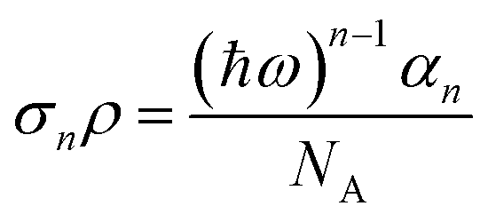
Using the above formulas, the effective multiphoton absorption coefficients (α3η) of MAPbBr3@MOF-5 are calculated to be α2η ≈ (1.23 ± 0.05) cm GW−1 for 2PA (800 nm), and α3η ≈ (27.4 ± 3.1) × 10−5 cm3 GW−2 for 3PA (1200 nm). Table 1 shows that the α2η of MAPbBr3@MOF-5 remains at the same level as perovskites, and the α3η of MAPbBr3@MOF-5 is an order of magnitude higher than that of perovskites. Moreover, the consistency of αnη for MAPbBr3@MOF-5 across different excitation intensities highlights its outstanding performance, especially in three-photon frequency conversion.
| Multiphoton excitation | α n η (cm GW−1) (at 800 nm) | α 3 η (10−5 cm3 GW−2) (at 1200 nm) | |
|---|---|---|---|
| MAPbBr3@MOF-5 | 1.23 ± 0.05 | 27.4 ± 3.1 | This work |
| MAPbBr3 single crystal | 7.35 ± 0.21 | Ref. 9,10,25 and 41 | |
| MAPbBr3 micro crystal | 1.90 | Ref. 25 and 26 | |
| MAPbI3 single crystal | 9.2 | 1.33 | Ref. 9,42 and 43 |
This result indicated the influence of the MOF-5 framework in confining MAPbBr3 QDs and providing protection, significantly enhancing their nonlinear optical properties. Recent studies have shown that due to variations in surface free energy, PeQDs tend to nucleate and grow within the pores of MOFs, as this process can reduce the energy barrier and critical radius.31,44 Without the confinement of pores, PeQDs would aggregate and cause fluorescence quenching. When MAPbBr3 is encapsulated into MOF-5, its growth is restricted by the pores of MOF-5, leading to more effective surface passivation. The quantum confinement effect will significantly impact the band structure and dielectric properties of PeQDs, leading to substantial changes in the multiphoton absorption coefficient.45 This surface passivation can reduce nonradiative recombination at the surface traps and increase the probability of multiphoton transitions.46–48 Additionally, the presence of local field effects may enhance the nonlinear optical properties of the composite.46 Above all, interfacial energy transfer from transition-metal ions (Zn2+) may enhance their optical performance.49 Therefore, MAPbBr3 QDs encapsulated in MOF-5 exhibit a significantly enhanced multiphoton absorption coefficient.
Conclusions
In summary, we have successfully embedded MAPbBr3 QDs into the pores of mesoporous MOF-5 through a stepwise immersion strategy. The resulting MAPbBr3@MOF-5 composites not only exhibit excellent optical performance but also demonstrate outstanding long-term stability and thermal stability. Furthermore, the confinement and surface passivation offered by the MOF-5 framework significantly enhance the nonlinear optical properties of the composites. Specifically, the two-photon absorption coefficient of MAPbBr3@MOF-5 is comparable to that of pure MAPbBr3 perovskite, while its three-photon absorption coefficient is an order of magnitude greater than that of the pure perovskite. Given its exceptional optical characteristics and high stability, the MAPbBr3@MOF-5 composites present great potential for applications in biomedicine, optoelectronic devices, and future photonic integration technologies.Data availability
The data supporting this article have been included as part of the ESI.†Conflicts of interest
The authors declare no competing financial interest.Acknowledgements
This work is supported by the STI 2030-Major Project (2022ZD0209900), the National Natural Science Foundation of China (No. 11904206), the Instrument Improvement Funds of Shandong University Public Technology Platform (ts20230103), the Shenzhen Science and Technology Program (JCYJ20220531103016036), and the Shenzhen Key Laboratory of 2D Metamaterials for Information Technology (ZDSYS201707271014468).Notes and references
- F. Arabpour Roghabadi, M. Alidaei, S. M. Mousavi, T. Ashjari, A. S. Tehrani, V. Ahmadi and S. M. Sadrameli, J. Mater. Chem. A, 2019, 7, 5898–5933 RSC.
- H. Zhang, T. Yu, C. Wang, R. Jia, A. A. A. Pirzado, D. Wu, X. Zhang, X. Zhang and J. Jie, ACS Nano, 2022, 16, 6394–6403 CrossRef CAS PubMed.
- G. Xing, N. Mathews, S. S. Lim, N. Yantara, X. Liu, D. Sabba, M. Grätzel, S. Mhaisalkar and T. C. Sum, Nat. Mater., 2014, 13, 476–480 CrossRef CAS PubMed.
- H. R. Jung, Y. Cho and W. Jo, Adv. Opt. Mater., 2022, 10, 2102175 CrossRef CAS.
- X. Wu, B. Zhou, J. Zhou, Y. Chen, Y. Chu and J. Huang, Small, 2018, 14, 1800527 CrossRef PubMed.
- Q. V. Le, K. Hong, H. W. Jang and S. Y. Kim, Adv. Electron. Mater., 2018, 4, 1800335 CrossRef.
- H.-C. Wang, Z. Bao, H.-Y. Tsai, A.-C. Tang and R.-S. Liu, Small, 2018, 14, 1702433 CrossRef PubMed.
- H. Huang, A. S. Susha, S. V. Kershaw, T. F. Hung and A. L. Rogach, Adv. Sci., 2015, 2, 1500194 CrossRef PubMed.
- F. O. Saouma, D. Y. Park, S. H. Kim, M. S. Jeong and J. I. Jang, Chem. Mater., 2017, 29, 6876–6882 CrossRef CAS.
- T.-C. Wei, S. Mokkapati, T.-Y. Li, C.-H. Lin, G.-R. Lin, C. Jagadish and J.-H. He, Adv. Funct. Mater., 2018, 28, 1707175 CrossRef.
- R. Medishetty, J. K. Zaręba, D. Mayer, M. Samoć and R. A. Fischer, Chem. Soc. Rev., 2017, 46, 4976–5004 RSC.
- R. Shi, X. Han, J. Xu and X.-H. Bu, Small, 2021, 17, 2006416 CrossRef CAS PubMed.
- G. Niu, X. Guo and L. Wang, J. Mater. Chem. A, 2015, 3, 8970–8980 RSC.
- K. J. Lee, J. H. Lee, S. Jeoung and H. R. Moon, Acc. Chem. Res., 2017, 50, 2684–2692 CrossRef CAS PubMed.
- C. Zhang, B. Wang, W. Li, S. Huang, L. Kong, Z. Li and L. Li, Nat. Commun., 2017, 8, 1138 CrossRef PubMed.
- H. Wu, P. Ran, L. Yao, H. Cai, W. Cao, Y. Cui, Y. Michael Yang, D. Yang and G. Qian, Chem. Eng. J., 2024, 491, 152098 CrossRef CAS.
- S. Cao, G. Gody, W. Zhao, S. Perrier, X. Peng, C. Ducati, D. Zhao and A. K. Cheetham, Chem. Sci., 2013, 4, 3573–3577 RSC.
- K. Shen, L. Zhang, X. Chen, L. Liu, D. Zhang, Y. Han, J. Chen, J. Long, R. Luque, Y. Li and B. Chen, Science, 2018, 359, 206–210 CrossRef CAS PubMed.
- L.-G. Qiu, T. Xu, Z.-Q. Li, W. Wang, Y. Wu, X. Jiang, X.-Y. Tian and L.-D. Zhang, Angew. Chem., Int. Ed., 2008, 47, 9487–9491 CrossRef CAS PubMed.
- J. Ren, T. Li, X. Zhou, X. Dong, A. V. Shorokhov, M. B. Semenov, V. D. Krevchik and Y. Wang, Chem. Eng. J., 2019, 358, 30–39 CrossRef CAS.
- W.-K. Jiang, T.-T. Huang, D.-X. Lv, Z.-H. Zhu, H.-H. Zou and F.-P. Liang, Cryst. Growth Des., 2024, 24, 9692–9700 CrossRef CAS.
- S. Jin, H.-J. Son, O. K. Farha, G. P. Wiederrecht and J. T. Hupp, J. Am. Chem. Soc., 2013, 135, 955–958 CrossRef CAS PubMed.
- S. Huang, Z. Li, L. Kong, N. Zhu, A. Shan and L. Li, J. Am. Chem. Soc., 2016, 138, 5749–5752 CrossRef CAS PubMed.
- D. Zhang, Y. Xu, Q. Liu and Z. Xia, Inorg. Chem., 2018, 57, 4613–4619 CrossRef CAS PubMed.
- W. Chen, S. Bhaumik, S. A. Veldhuis, G. Xing, Q. Xu, M. Grätzel, S. Mhaisalkar, N. Mathews and T. C. Sum, Nat. Commun., 2017, 8, 15198 CrossRef CAS PubMed.
- Y. Gao, S. Wang, C. Huang, N. Yi, K. Wang, S. Xiao and Q. Song, Sci. Rep., 2017, 7, 45391 CrossRef CAS PubMed.
- H. Li, M. Eddaoudi, M. O'Keeffe and O. M. Yaghi, Nature, 1999, 402, 276–279 CrossRef CAS.
- C. Vautier-Giongo and H. O. Pastore, J. Colloid Interface Sci., 2006, 299, 874–882 CrossRef CAS PubMed.
- V. Malgras, S. Tominaka, J. W. Ryan, J. Henzie, T. Takei, K. Ohara and Y. Yamauchi, J. Am. Chem. Soc., 2016, 138, 13874–13881 CrossRef CAS PubMed.
- D. N. Dirin, L. Protesescu, D. Trummer, I. V. Kochetygov, S. Yakunin, F. Krumeich, N. P. Stadie and M. V. Kovalenko, Nano Lett., 2016, 16, 5866–5874 CrossRef CAS PubMed.
- Q. Fan, Z. Yan, H. Zhou, Y. Yao, Z. Wang, Y. Gao, Y. Wang, S. Lu, M. Liu and W. Ji, J. Mater. Chem. C, 2023, 11, 5788–5795 RSC.
- M.-H. Yu, D. Zhao, R.-J. Zhang, Q.-X. Yao, L. Jia and Q. Zong, Ceram. Int., 2024, 50, 11766–11775 CrossRef CAS.
- Y.-X. Bi, D. Zhao, R.-J. Zhang, L. Jia and Q. Zong, Microchem. J., 2024, 205, 111375 CrossRef CAS.
- J. Zheng, G. Yue, Z. A. Zhou, H. Li, L. Hou, C. Sun, X. Li, L. Kang, N. Wang, Y. Zhao and S. Zhou, Adv. Funct. Mater., 2023, 33, 2300607 CrossRef CAS.
- J. Wang, D. Huang, Y. Zhou, C. Liao, P. Guo, Z. Li, G. Zhou, X. Yu and J. Hu, Small Struct., 2023, 4, 2200391 CrossRef CAS.
- D. Zhang, W. Zhou, Q. Liu and Z. Xia, ACS Appl. Mater. Interfaces, 2018, 10, 27875–27884 CrossRef CAS PubMed.
- X. Xiang, J. Li, J. Xue and Z. Fu, Langmuir, 2023, 39, 5315–5322 CrossRef CAS PubMed.
- Z. Xie, X. Li, R. Li, S. Lu, W. Zheng, D. Tu, Y. Feng and X. Chen, Nanoscale, 2020, 12, 17113–17120 RSC.
- X. Jiang, J. Zhang, R. Fan, X. Zhou, K. Zhu and Y. Yang, ACS Appl. Mater. Interfaces, 2022, 14, 49945–49956 CrossRef CAS PubMed.
- N. Liaros and J. T. Fourkas, Laser Photonics Rev., 2017, 11, 1700106 CrossRef.
- G. Walters, B. R. Sutherland, S. Hoogland, D. Shi, R. Comin, D. P. Sellan, O. M. Bakr and E. H. Sargent, ACS Nano, 2015, 9, 9340–9346 CrossRef CAS PubMed.
- F. Chun, B. Zhang, Y. Li, W. Li, M. Xie, X. Peng, C. Yan, Z. Chen, H. Zhang and W. Yang, Chem. Eng. J., 2020, 399, 125715 CrossRef CAS.
- D. Yang, C. Xie, J. Sun, H. Zhu, X. Xu, P. You, S. P. Lau, F. Yan and S. F. Yu, Adv. Opt. Mater., 2016, 4, 1053–1059 CrossRef CAS.
- C. Ren, Z. Li, L. Huang, X. Xiong, Z. Nie, Y. Yang, W. Zhu, W. Yang and L. Wang, Nanoscale, 2022, 14, 4216–4224 RSC.
- F. Zhou, X. Ran, D. Fan, S. Lu and W. Ji, Adv. Opt. Mater., 2021, 9, 2100292 CrossRef CAS.
- H. He, Y. Cui, B. Li, B. Wang, C. Jin, J. Yu, L. Yao, Y. Yang, B. Chen and G. Qian, Adv. Mater., 2019, 31, 1806897 CrossRef PubMed.
- S. A. Veldhuis, Y. K. E. Tay, A. Bruno, S. S. H. Dintakurti, S. Bhaumik, S. K. Muduli, M. Li, N. Mathews, T. C. Sum and S. G. Mhaisalkar, Nano Lett., 2017, 17, 7424–7432 CrossRef CAS PubMed.
- B. H. Zhu, H. C. Zhang, J. Y. Zhang, Y. P. Cui and Z. Q. Zhou, Appl. Phys. Lett., 2011, 99, 021908 CrossRef.
- S. Mollick, T. N. Mandal, A. Jana, S. Fajal and S. K. Ghosh, Chem. Sci., 2019, 10, 10524–10530 RSC.
Footnotes |
| † Electronic supplementary information (ESI) available. See DOI: https://doi.org/10.1039/d4tc05087h |
| ‡ Both Wenqing Wang and Renhua Liu contributed equally to this manuscript. |
| This journal is © The Royal Society of Chemistry 2025 |