DOI:
10.1039/D4SC02794A
(Edge Article)
Chem. Sci., 2024,
15, 11761-11774
Molecular “backbone surgery” of electron-deficient heteroarenes based on dithienopyrrolobenzothiadiazole: conformation-dependent crystal structures and charge transport properties†
Received
27th April 2024
, Accepted 18th June 2024
First published on 18th June 2024
Abstract
Electron-deficient heteroarenes based on dithienopyrrolobenzothiadiazole (BTP) have been highly attractive due to their fascinating packing structures, broad absorption profiles, and promising applications in non-fullerene organic solar cells. However, the control of their crystal structures for superior charge transport still faces big challenges. Herein, a conformation engineering strategy is proposed to rationally manipulate the single crystal structure of BTP-series heteroarenes. The parent molecule BTPO-c has a 3D network crystal structure, which originates from its banana-shaped conformation. Subtracting one thiophene moiety from the central backbone leads to a looser brickwork crystal structure of the derivative BTPO-z because of its interrupted angular-shaped conformation. Further subtracting two thiophene moieties results in the derivative BTPO-l with a compact 2D-brickwork crystal structure due to its quasi-linear conformation with a unique dimer packing structure and short π–π stacking distance (3.30 Å). Further investigation of charge-transport properties via single-crystal organic transistors demonstrates that the compact 2D-brickwork crystal structure of BTPO-l leads to an excellent electron mobility of 3.5 cm2 V−1 s−1, much higher than that of BTPO-c with a 3D network (1.9 cm2 V−1 s−1) and BTPO-z with a looser brickwork structure (0.6 cm2 V−1 s−1). Notably, this study presents, for the first time, an elegant demonstration of the tunable single crystal structures of electron-deficient heteroarenes for efficient organic electronics.
1 Introduction
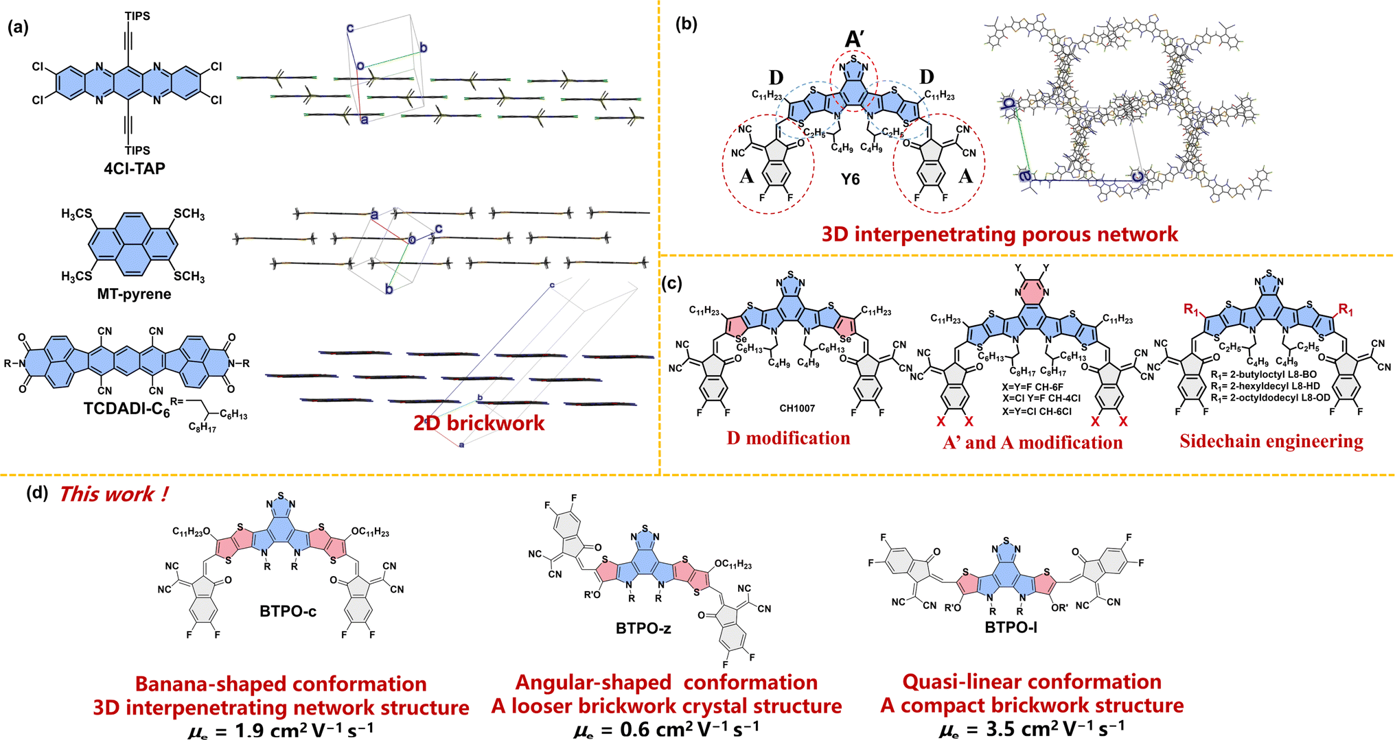
In the past few years, π-conjugated heteroarenes have attracted great attention as organic semiconductors (OSs) due to their special molecular characteristics and decent charge transport properties. Therefore, they have been widely applied in a variety of organic electronic devices, such as organic field-effect transistors (OFETs),1–5 organic solar cells (OSCs)6–9 and organic electrochemical transistors (OECTs).10–14 Among them, an electron-deficient heteroarene, namely dithienopyrrolobenzothiadiazole derivative (BTP), is very attractive due to its broad absorption, intriguing packing structures, and unique physicochemical properties, leading to great success in non-fullerene OSC applications.15–17 However, the control of its crystal structures for superior charge transport in OFETs is not an easy task. The mobility of BTP derivatives is usually orders of magnitude smaller compared to that of other heteroarenes.18–22
Charge carrier transport in OSs is determined by the electronic structure in solids, which is governed by the properties of the single molecule itself and molecular packing modes of dimers (or molecular clusters).23–27 It is widely accepted that a 2D-brickwork structure is one of the most promising molecular packing motifs for efficient charge transport.28–30 For example, the single crystals of several high-mobility arenes and heteroarenes show 2D-brickwork structures (such as 4Cl-TAP, MT-pyrene, and TCDADI-C6, Fig. 1a). In this brickwork structure, a mutual balance between the sizes of side groups and backbones is adjusted, which is beneficial for charge transport. A high charge carrier mobility of over 10 cm2 V−1 s−1 can be achieved in OFETs based on this brickwork structure, which often follows the band-like charge transporting mechanism.31–33 On the other hand, most BTP derivatives demonstrate a so-called “3D-interpenetrating porous network” as a result of their unique acceptor–donor–acceptor′–donor–acceptor (ADA′DA) configuration and various types of interactions between D and A (A′) units (Fig. 1b).15,34 Although this distinctive 3D transport network can minimize the hole and electron transport distance with balanced hole and electron transport properties, it may not be so efficient in OFETs that mainly require the efficient transport of charge carriers in the parallel direction between the contact electrodes.
 |
| | Fig. 1 (a) The chemical structures and crystal packing modes of 4Cl-TAP (CCDC number: 1845318), MT-pyrene (CCDC number: 2076078), and TCDADI-C6 (CCDC number: 2255617). (b) The chemical structures and crystal packing modes of the most famous BTP derivative Y6 (CCDC number: 2015912). The long alkyl chains are simplified with methyl or isopropyl and the hydrogen atoms are omitted for clarity. (c) Design strategies and chemical structures of BTP derivatives in the literature. (d) The chemical structures of BTPO-c, BTPO-z, and BTPO-l in this work. | |
Rational molecular design can tune the packing motifs of organic single crystals.35 As for BTP derivatives, the modification of fused-ring central cores (D modification and A′ modification), the end group variation (A modification) and sidechain engineering have been rationalized to change the molecular properties (Fig. 1c).36–40 However, the above strategies almost do not change the crystal structures of the resultant BTP derivatives that exhibit the same “3D-interpenetrating porous network” according to the corresponding single-crystal X-ray diffractometry.41–44 Therefore, controlling the crystal structure of BTP-series heteroarenes represents a great challenge, yet it is crucial to a better understanding of the structure–property correlations of organic semiconducting materials. We speculate that the underlying reason why these single-crystal structures remain the same (3D-interpenetrating porous network) is that these design strategies do not alter the molecular conformation based on the parent molecule BTP, which has a “banana”-shaped conformation due to the S⋯O![[double bond, length as m-dash]](https://www.rsc.org/images/entities/char_e001.gif) C intramolecular interaction between central cores and end groups. In sharp contrast, the heteroarenes that show the “2D-brickwork structure” often possess linear backbone conformation (such as 4Cl-TAP and TCDADI-C6, Fig. 1a). Different backbone conformations may lead to varied intermolecular interactions, causing distinct single-crystal packing motifs.45
C intramolecular interaction between central cores and end groups. In sharp contrast, the heteroarenes that show the “2D-brickwork structure” often possess linear backbone conformation (such as 4Cl-TAP and TCDADI-C6, Fig. 1a). Different backbone conformations may lead to varied intermolecular interactions, causing distinct single-crystal packing motifs.45
With these results, we propose that the control of single crystal structures using conformation engineering (i.e. through polishing the backbone structure) will be an innovative approach to realize high-mobility BTP-series heteroarenes. To embody this, the length of electron-deficient central cores is shortened from heptacyclic to hexacyclic and pentacyclic based on the parent BTPO-c with banana conformation, affording two derivatives BTPO-z and BTPO-l (Fig. 1d). The newly synthesized BTPO-z and BTPO-l possess “angular” and “quasi-linear”-shaped conformations, respectively. We find that the crystal packing topology is dependent on the molecular conformation. To our delight, a very compact 2D brickwork structure with a short π–π stacking distance is found in the corresponding single-crystal structure of BTPO-l by changing the banana conformation to the quasi-linear conformation. As a result, the electron mobility of single-crystal organic field-effect transistors (SC-OFETs) based on BTPO-l reaches 3.5 cm2 V−1 s−1, significantly outperforming BTPO-c, BTPO-z and all the other reported BTP-series heteroarenes.
2 Results and discussion
2.1. Design, synthesis, and characterization
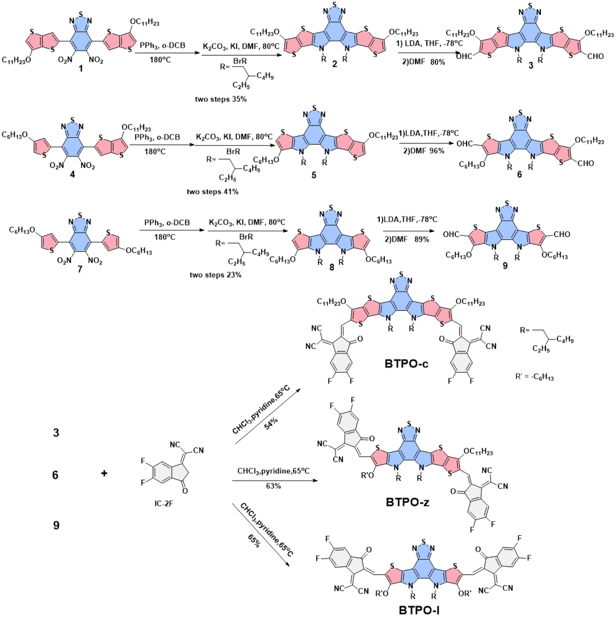
The chemical structures of the three BTP derivatives are shown in Fig. 1d and Scheme 1. Compared to the parent molecule BTPO-c, BTPO-z and BTPO-l were designed by replacing the alkoxy thieno[3,2-b]thiophene units in the central cores with alkoxy thiophene units on one side and on both sides. To eliminate the effects of shortening of conjugated central cores on solubility, the n-undecyloxy side chains on thieno[3,2-b]thiophene units were synchronously shortened to n-hexyloxy side chains on thiophene units. Therefore, the effects of molecular conformation on single-crystal packing motifs and the related SC-OFET performance can be systematically investigated through these materials. The synthetic routes to the three heteroarenes are shown in Scheme 1. The starting compounds 1, 4, and 7 have undergone double intramolecular Cadogan reductive cyclization in the presence of triphenylphosphine at a high temperature of 180 °C, followed by the addition of 1-bromo-2-ethylhexane under alkaline conditions at 80 °C. The important dialdehyde intermediates 3, 6, and 9 were then synthesized using lithium diisopropylamide and N,N-dimethylformamide. Finally, the target BTPO-c, BTPO-z, and BTPO-l were obtained through Knoevenagel condensation in yields of 50–60%.46 The detailed descriptions of the synthetic procedures with the corresponding nuclear magnetic resonance spectra and mass spectra are summarized in the ESI.† All three heteroarenes have decent solubility in chloroform but show poor solubility in acetone, methanol and ethanol. The solubility information gives out the choice of good and poor solvent to grow the corresponding single crystals with the vapor diffusion method. As shown by the thermogravimetric analysis (TGA) curves in Fig. S1,† all three heteroarenes possess good thermal stability with thermal decomposition temperatures (Td, 5% weight loss) of over 300 °C (Table 1).
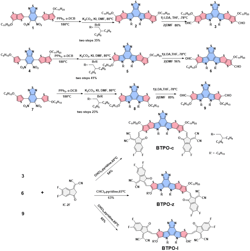 |
| | Scheme 1 Synthetic route to obtain BTPO-c, BTPO-z, and BTPO-l. | |
Table 1 Summary of the properties of BTPO-c, BTPO-z and BTPO-l
| Heteroarenes |
λ
max
(nm) |
λ
onset
(nm) |
λ
max
(nm) |
λ
onset
(nm) |
E
optg
(eV) |
E
HOMO
(eV) |
E
LUMO
(eV) |
E
eleg
(eV) |
T
(°C)f |
|
In chloroform solution.
In neat films.
Obtained with the equation: Eoptg = 1240/λonset.
Measured by the cyclic voltammetry (CV) method.
Obtained with the equation: Eeleg = ELUMO − EHOMO.
5% weight loss temperature obtained from TGA curves.
|
| BTPO-c |
701 |
741 |
748 |
792 |
1.57 |
−5.73 |
−3.75 |
1.98 |
345 |
| BTPO-z |
691 |
737 |
746 |
807 |
1.54 |
−5.69 |
−3.75 |
1.94 |
327 |
| BTPO-l |
686 |
723 |
714 |
755 |
1.64 |
−5.80 |
−3.79 |
2.01 |
329 |
2.2. Optical and electronic properties
The optical properties of BTPO-c, BTPO-z and BTPO-l were investigated by using their solution and thin-film UV-vis-NIR absorption spectra (Fig. 2a and b). The key optical data are summarized in Table 1. All three compounds present intensive absorption from 600 nm to 800 nm in chloroform solution. It is reasonable that with the decrease of the conjugated length of central cores, the maximum absorption peak blueshifts from BTPO-c (741 nm), BTPO-z (737 nm) to BTPO-l (723 nm). As for the thin-film state, the onsets of absorption spectra of all three materials present redshift compared with those in the solution state as a result of solid-state aggregation. Unlike in chloroform solution, the absorption onset of thin-film BTPO-z is more redshifted compared to that of thin-film BTPO-c, leading to its lower optical bandgap of 1.54 eV. The distinct difference in absorption spectra between chloroform solution and thin films indicates that BTPO-z may have relatively strong aggregation properties in the solid state as evidenced by the significantly enhanced intensity of the 0-1 shoulder peak of BTPO-z (Fig. 2b). Furthermore, the energy levels of BTPO-c, BTPO-z and BTPO-l were measured through electrochemical cyclic voltammetry (CV) methods. The calculated highest occupied molecular orbital (HOMO)/lowest unoccupied molecular orbital (LUMO) levels of the three heteroarenes in thin films are summarized in Fig. 2c and Table 1 with the corresponding cyclic voltammograms shown in Fig. S2.† It is found that the backbone length variation affects the energy levels. Compared to the LUMO/HOMO levels of the parent molecule BTPO-c (−3.75 eV/−5.73 eV), BTPO-l has the deepest LUMO/HOMO levels of −3.79/−5.80 eV, which are more beneficial for electron injection from Au electrodes. Besides, the electrochemical bandgaps of BTPO-c, BTPO-z and BTPO-l are determined to be 1.98 eV, 1.94 eV and 2.01 eV, respectively, whose trend is consistent with their optical bandgaps.
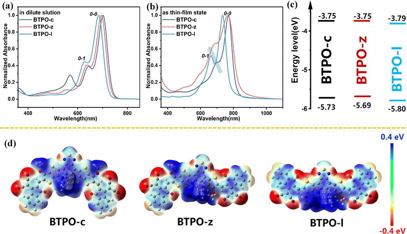 |
| | Fig. 2 (a and b) Normalized absorption spectra of BTPO-c, BTPO-z and BTPO-l in chloroform solution (a) and films (b); (c) the energy level schematic diagrams. (d) The calculated electrostatic potential diagrams of BTPO-c, BTPO-z and BTPO-l. | |
To theoretically understand the effects of conformation on intermolecular interactions, density functional theory (DFT) calculation was conducted at the B3LYP/6-31G (d) level with all long alkyl chains simplified with methoxy or isobutyl groups. The optimized conformation and the electrostatic potential (ESP) diagrams of the three heteroarenes are summarized in Fig. S3† and 2d. The calculated LUMO/HOMO levels of BTPO-c, BTPO-z and BTPO-l are −3.38/−5.59, −3.48/−5.67, and −3.62/−5.84 eV, respectively, which are consistent with the CV results (Table S1†).47 From the optimized geometry, BTPO-c, BTPO-z and BTPO-l adopt “banana”, “angular” and “quasi-linear” conformations, respectively, in accordance with our design strategies. When the thieno[3,2-b]thiophene units are replaced by thiophene units, the distance from the S atom (on the central core) to the O atom (on the end group) is enlarged from 2.69 Å to 2.72 Å, indicating a slightly lower non-covalent interaction after thiophene substitutions. All three heteroarenes exhibit good planarity between the central cores and end groups as the dihedral angles between these two parts are all below 2°. According to ESP diagrams, the molecular conformation has an influence on ESP distribution, which may lead to different intermolecular interactions. For parent BTPO-c with the banana conformation, the positive ESP is mainly located at the central part of the backbone (Fig. 2d, left). For the angular-conformation BTPO-z, the positive ESP is largely located on the left side of the backbone (Fig. 2d, middle), while it is more delocalized along the backbone in the case of quasi-linear BTPO-l (Fig. 2d, right). This distinct ESP distribution can further affect the intermolecular interactions, leading to different crystal packing. It should be noted that in Table S1† the calculated dipole moment of BTPO-c is 3.66, which is much higher than those of BTPO-s (1.25) and BTPO-l (1.49), indicating that a strong intermolecular interaction caused by molecular polarity may exist in BTPO-c. Note that the above calculation focuses on the single molecule without considering the neighboring molecules, which cannot totally reflect the molecular packing motifs in the actual single crystals.
2.3. Thin-film morphologies and microstructures
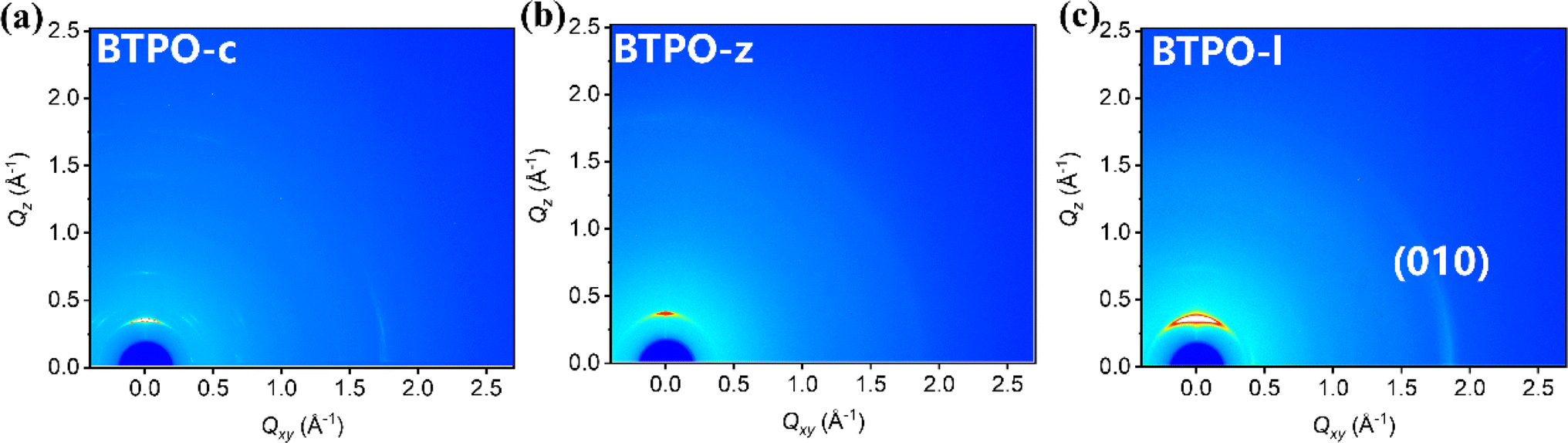
Grazing-incidence wide-angle X-ray scattering (GIWAXS) technology is an important method to investigate the film morphology. Fig. 3 shows the GIWAXS patterns of pristine films based on BTPO-c, BTPO-z and BTPO-l and Fig. S4† depicts the corresponding in-plane and out-of-plane averaged GIWAXS profiles. Table S2† summarizes the detailed information of (100) and (010) peaks. In the in-plane direction, intense (010) peaks appear in BTPO-c and BTPO-l films, which indicates the existence of prior edge-on orientation.48–50 The edge-on orientation is seldom found in BTPO-series heteroarenes but provides an optimal packing structure for charge mobility in OFET devices.51–55 Although BTPO-c shows the largest d-spacing values both in π–π stacking and lamellar stacking, the corresponding coherence length (CL) of BTPO-c (182.4 Å) is much higher than those of BTPO-z and BTPO-l. This implies its extremely high crystallinity. Besides, the higher ordered (200) peak is also observed in the GIWAXS patterns of BTPO-c with a number of other diffraction signals, supporting the high crystallinity of BTPO-c. For BTPO-z, the π–π stacking distance is 3.38 Å with a CL value of 31.2 Å, while for BTPO-l the π–π stacking distance is similar (3.40 Å) with a higher CL value of 54.9 Å. According to GIWAXS measurements, BTPO-c shows the highest crystallinity among the three thin films induced by the large molecular polarity and BTPO-z shows the lowest crystallinity, which reflects the influence of molecular conformation on the order of molecular packing. Although BTPO-l exhibits the strongest (010) peak among the three molecules, the much lower CL values compared to that of BTPO-c suggest less ordered (010) packing in the thin film of BTPO-l, which may not be favorable for carrier transportation. Furthermore, the thin film microstructures of BTPO-c, BTPO-z and BTPO-l were investigated with an atomic force microscope (AFM) with the corresponding height and phase images shown in Fig. S5.† The thin film of BTPO-l shows the smoothest surface with a root-mean-square (RMS) roughness value of 0.967 nm. For BTPO-z, its surface is roughest with a RMS value of 12.9 nm, indicating the very strong aggregation properties of BTPO-z, which are also observed in the UV-vis-NIR measurements (Fig. 2b). The enhanced roughness of BTPO-z can cause traps at the interface between the active layer and electrodes or between the active layer and dielectric layer in thin-film OFETs, which thus inhibits charge transport in the corresponding devices.56,57
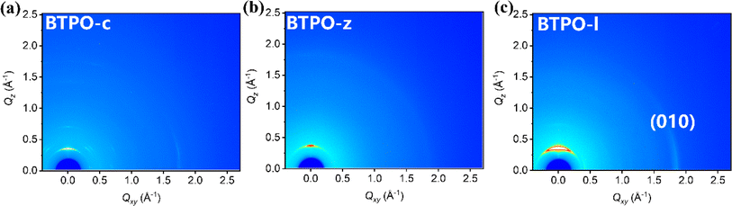 |
| | Fig. 3 2D-GIWAXS patterns: BTPO-c film (a), BTPO-z film (b), and BTPO-l film (c). | |
2.4. Thin-film organic field-effect transistors
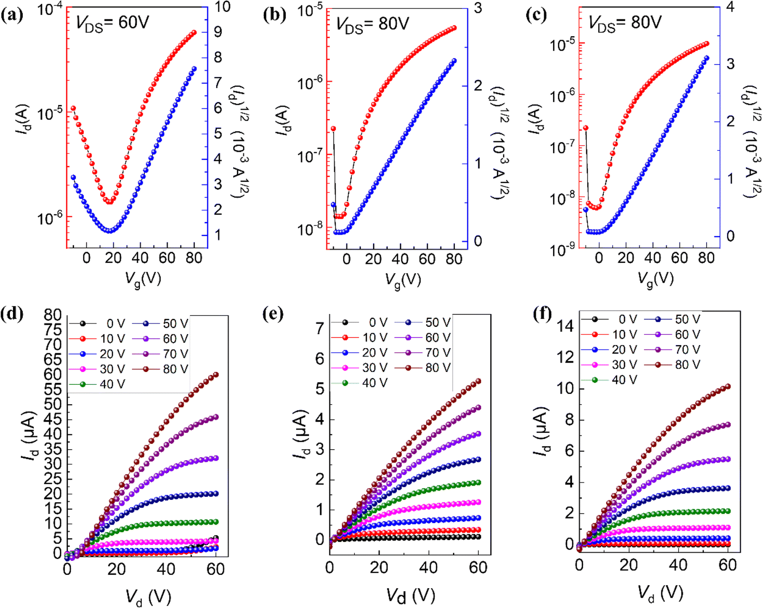
To find out the different charge transport properties caused by different molecular conformations, top gate/bottom contact (TGBC) thin-film OFETs based on BTPO-c, BTPO-z and BTPO-l were fabricated. Here, we used silver as the gate electrode, gold as the source and drain electrodes and polymethyl methacrylate (PMMA) as the dielectric materials. The processing solvent for organic semiconductors is chloroform (the concentration is 5 mg mL−1) and the annealing temperature is 90 °C. The detailed fabrication procedures and characteristic measurements are provided in the ESI.† The transfer and output curves of thin-film OFET devices based on BTPO-c, BTPO-z and BTPO-l are shown in Fig. 4 and the corresponding characteristic parameters are listed in Table S3.† All three materials show unipolar n-type charge transport properties. Due to their relatively low crystallinity and over-aggregation properties, BTPO-z-based devices possess the lowest electron mobility of 0.006 cm2 V−1 s−1. Although the thin film of BTPO-c is also rough, the highly ordered molecular packing contributes to the highest electron mobility of 0.1 cm2 V−1 s−1 achieved by the corresponding thin-film OFETs. The devices based on the thin films of BTPO-l exhibit the maximum electron mobility of 0.02 cm2 V−1 s−1 owing to the moderate crystallinity between BTPO-c and BTPO-z, strong molecular packing and smooth film surface. These device results are consistent with the previously mentioned GIWAXS and AFM measurements, which reveal that molecular conformation control is a promising and simple method to change the film morphology and the charge transport properties of thin-film OFETs.
 |
| | Fig. 4 (a–c) OFET transfer characteristics of films of BTPO-c, BTPO-z, and BTPO-l, respectively, and (d–f) OFET output curves of films of BTPO-c, BTPO-z, and BTPO-l, respectively. | |
2.5. Single-crystal packing analysis
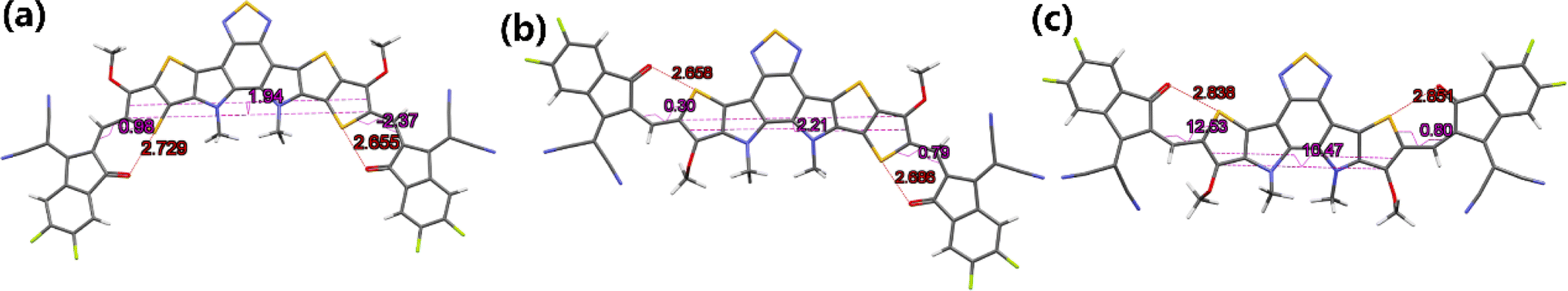
To further understand the effects of molecular conformation on solid-state packing, it is necessary to analyze the single-crystal structures of BTPO-c, BTPO-z and BTPO-l. In this study, we used the vapor diffusion method by using chlorobenzene as good solvent and methanol as poor solvent to obtain the single crystals of these three heteroarenes, as summarized in the ESI.† Fortunately, all three single-crystal structures are successfully analyzed. Fig. 5 exhibits the monomolecular structures of the three heteroarenes directly extracted from single-crystal X-ray diffraction results. Here, all the side chains are simplified with methyl or methoxy groups for clarity. The same as the DFT calculations, BTPO-c, BTPO-z and BTPO-l present “banana”, “angular” and “quasi-linear” molecular conformations, respectively. However, due to the influence of intermolecular interactions, the detailed metrical parameters are different from the theoretical calculation. Although BTPO-c and BTPO-l are symmetrical in terms of chemical structures, the actual molecular geometries are unsymmetrical due to the difference in intermolecular interactions on each side. These observed monomolecular differences between calculation results and real crystals have close relationships with the corresponding packing motifs in the single crystal (discussed below).
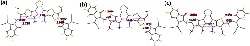 |
| | Fig. 5 Monomolecular crystallographic structures of (a) BTPO-c, (b) BTPO-z and (c) BTPO-l. Here, all the side chains are simplified with methyl or methoxy for clarity. | |
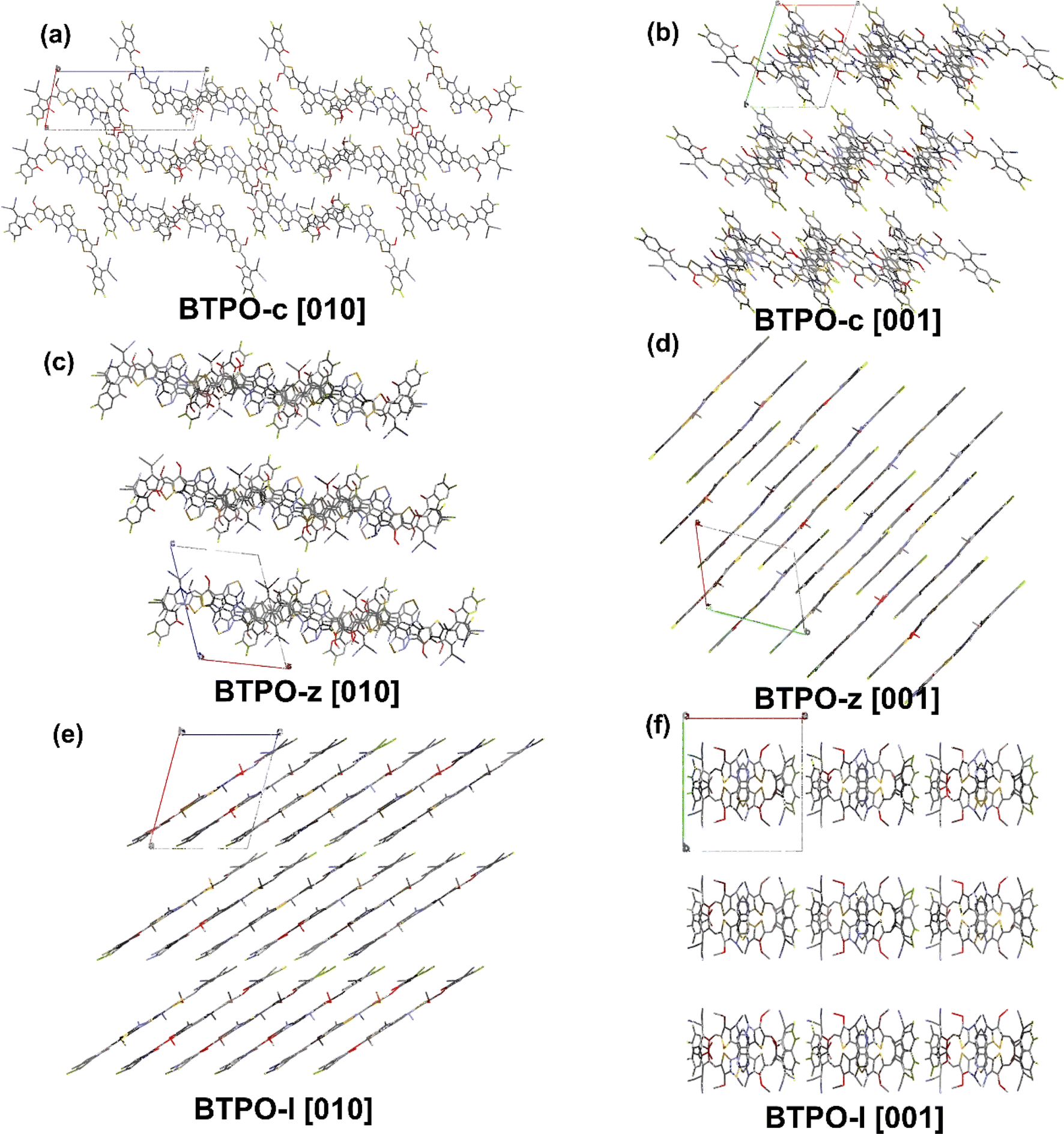
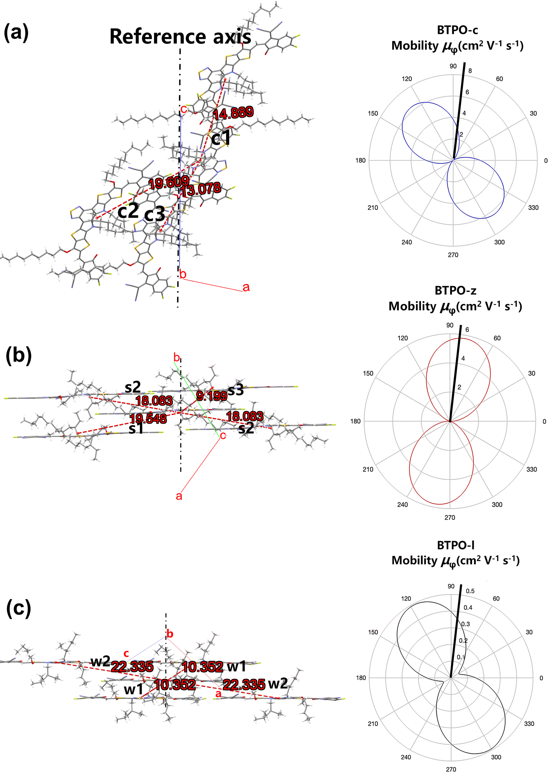
The single-crystal packing structures of BTPO-c, BTPO-z and BTPO-l in the [100], [010] and [001] directions are listed in Fig. 6 and S6† with the corresponding crystallographic data listed in Table S4.† Here, all side chains were also simplified with methyl and methoxy for clarification. Although all three heteroarenes build up crystal packing networks through the interactions between the end groups and the end groups or the end groups and the central cores, different single-crystal packing patterns are formed in BTPO-c, BTPO-z and BTPO-l. Both BTPO-c and BTPO-z take triclinic systems with space groups ![[P with combining macron]](https://www.rsc.org/images/entities/i_char_0050_0304.gif) 1, while BTPO-l crystalizes in a monoclinic system with a more ordered space group Pc. The calculated packing coefficient increases from BTPO-c (62.9%), BTPO-z (64.2%) to BTPO-l (66.6%), indicating a more compact molecular packing in BTPO-l than those in BTPO-z and BTPO-c.58,59 For BTPO-c, the central backbones are connected by end group-end group interactions, which build a quasi-3D interpenetrating network (Fig. 6a and b). Every BTPO-c molecule interacts with three other molecules. As for BTPO-l, it forms a 2D brickwork structure (Fig. 6e). Besides, every BTPO-l molecule possesses π–π interactions with four other molecules. Although BTPO-z also forms a 2D brickwork structure, it shows a looser packing motif when compared to BTPO-l (Fig. 6c and d). The overlapping region of two neighboring molecules seems smaller than that of BTPO-l (Fig. 6d and e). The unit cell volume of BTPO-z is 3585.7 Å3, which is larger than that of BTPO-l (3130.8 Å3). The different crystal packing patterns of BTPO-c, BTPO-z and BTPO-l are formed by various dimer packing motifs, which have close ties with molecular conformations (vide infra).
1, while BTPO-l crystalizes in a monoclinic system with a more ordered space group Pc. The calculated packing coefficient increases from BTPO-c (62.9%), BTPO-z (64.2%) to BTPO-l (66.6%), indicating a more compact molecular packing in BTPO-l than those in BTPO-z and BTPO-c.58,59 For BTPO-c, the central backbones are connected by end group-end group interactions, which build a quasi-3D interpenetrating network (Fig. 6a and b). Every BTPO-c molecule interacts with three other molecules. As for BTPO-l, it forms a 2D brickwork structure (Fig. 6e). Besides, every BTPO-l molecule possesses π–π interactions with four other molecules. Although BTPO-z also forms a 2D brickwork structure, it shows a looser packing motif when compared to BTPO-l (Fig. 6c and d). The overlapping region of two neighboring molecules seems smaller than that of BTPO-l (Fig. 6d and e). The unit cell volume of BTPO-z is 3585.7 Å3, which is larger than that of BTPO-l (3130.8 Å3). The different crystal packing patterns of BTPO-c, BTPO-z and BTPO-l are formed by various dimer packing motifs, which have close ties with molecular conformations (vide infra).
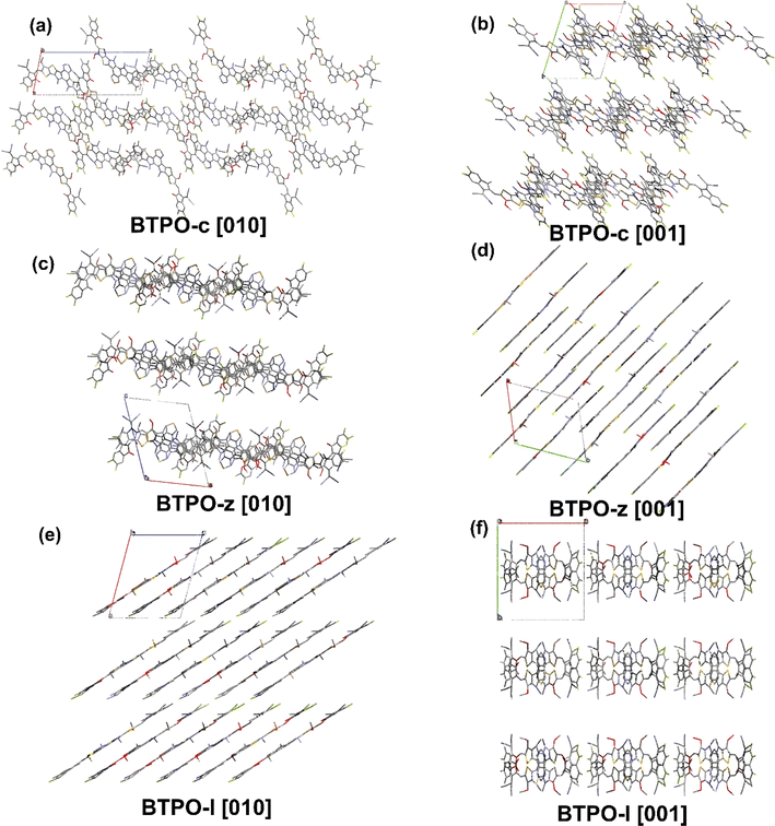 |
| | Fig. 6 Single-crystal packing structures of BTPO-c (a and b), BTPO-z (c and d) and BTPO-l (e and f) in the [010] and [001] directions, respectively. | |
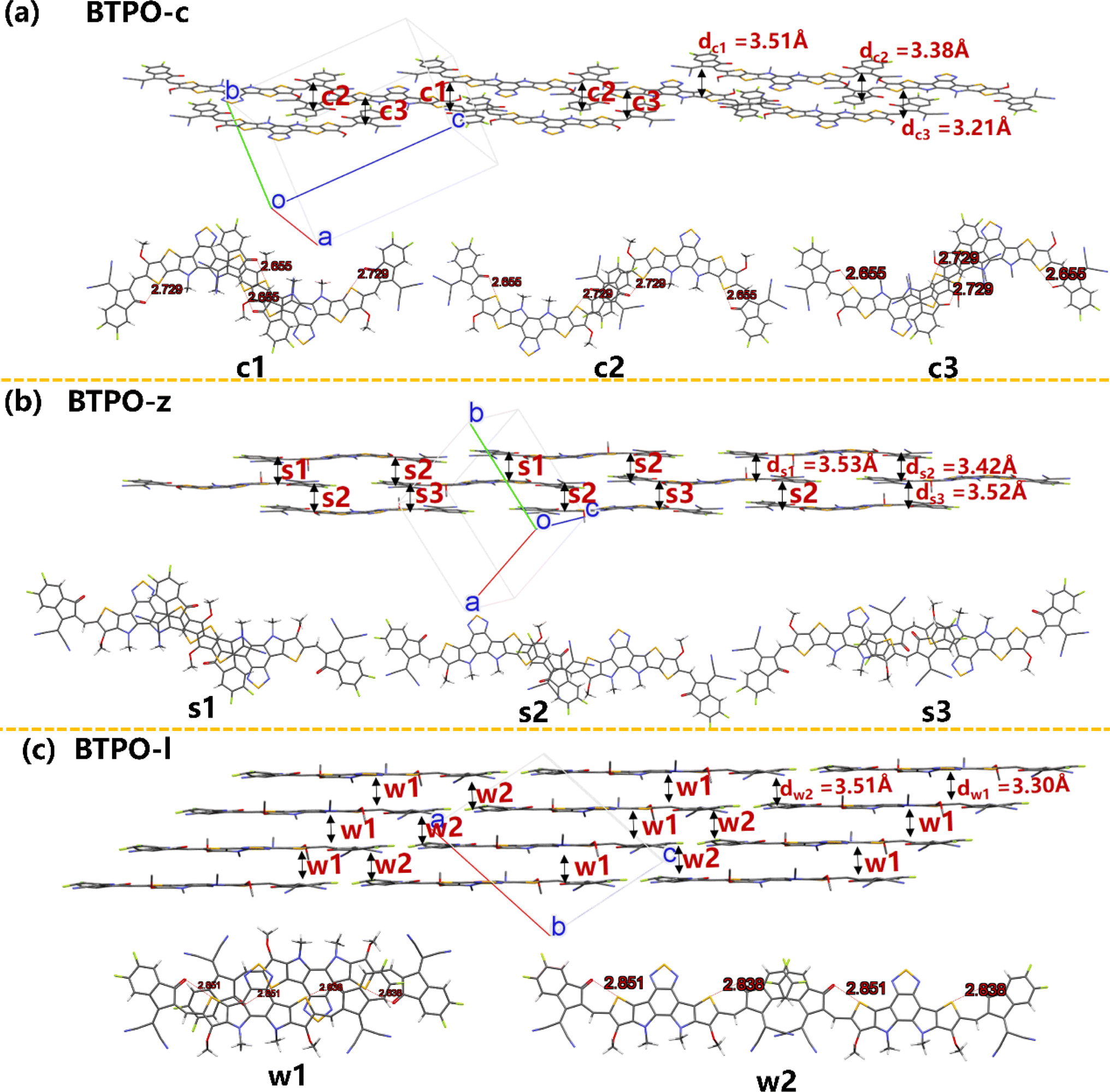
Fig. 7 exhibits the intermolecular packing motifs of BTPO-c, BTPO-z and BTPO-l along the π–π stacking direction in single crystals with the corresponding detailed dimer structure (top view). Besides, the average π–π stacking distance (d) and binding energy (ΔE) of dimers were calculated and are summarized in Table S5.† For BTPO-c, there are three kinds of dimers named c1 (central core-end group stacking), c2 (end group-end group stacking) and c3 (central core-end group stacking). The ΔE value of c1 and c3 is higher (∼2.0 eV), indicating that these two dimer structures are relatively stable. Besides, the d of c3 is the shortest (3.21 Å), implying that charge carriers transport fastest through the dimer c3. Every BTPO-c molecule interacts with two adjacent BTPO-c through the stable c1 and c3 and the relatively weaker c2 is like a bridge to connect the nearby backbones (Fig. 7a). In total, every BTPO-c interacts with three adjacent BTPO-c molecules. For the single crystal structure of BTPO-z, three kinds of dimers namely s1 (central core-end group stacking), s2 (monodirectional central core-end group stacking) and s3 (central core-end group stacking) are found. The three dimers show relatively long π–π distances of 3.42–3.53 Å (Fig. 7b). In this crystal structure, one BTPO-z molecule interacts with two BTPO-z molecules in the form of s1 and s2 on the thiophene[3,2-b]thiophene side of the central core, while it interacts with two other BTPO-z molecules through s2 and s3 on the thiophene side of the central core. Therefore, every BTPO-z connects with four nearby molecules. Although a 2D brickwork structure is formed in BTPO-z, this brickwork structure is loose due to larger π–π stacking distances (3.42–3.53 Å). In the case of BTPO-l, two types of dimers named w1 and w2 are sought out (Fig. 7c). The same as BTPO-z, every BTPO-l molecule interacts with four adjacent molecules through these two pairs of w1 and w2. Dimer w2 is constructed by end group-end group stacking with a short π–π distance of 3.30 Å. For dimer w1, there exists not only central core-end group stacking but also central core-central core interactions, contributing to a more compact 2D brickwork structure compared to that of BTPO-z. This compact 2D-brickwork crystal structure should be beneficial for efficient charge carrier transport.
 |
| | Fig. 7 The single-crystal packing diagrams of (a) BTPO-c, (b) BTPO-z and (c) BTPO-l along the π–π stacking direction with the corresponding dimer structures. Here, all the side chains are simplified with methyl or methoxy for clarity. | |
2.6. Computational theoretical calculation of the crystal packing motifs
In n-type organic semiconductors, the electron usually transports through intermolecular charge hopping and the rate of this process between two adjacent molecules mainly determines the single-crystal electron mobility. In this work, according to famous Marcus theory, the electron hopping rate (k) can be calculated using the Marcus–Hush equation as given in eqn (1),60| |  | (1) |
in which λe is the electronic reorganization energy, V is the electronic coupling value between two adjacent molecules in the above-mentioned dimers of the single-crystal structure, T is the temperature (here 298.15 K is chosen) and kB is the Boltzmann constant. Therefore, in a single-crystal structure, only V and λe are unknown, which can both be obtained with first-principles calculations. The detailed calculation methods of V and λe are described in the ESI.†
Based on eqn (1), the lower λe is beneficial for promising electron mobility. The corresponding values of λe for BTPO-c, BTPO-z and BTPO-l are listed in Table S5.† The λe decreases from BTPO-l, BTPO-z to BTPO-c, indicating that the larger conjugated central cores can reduce the λe. The V value is determined by the molecular arrangement in the single crystal and stands for the intermolecular electronic coupling, which needs to be maximized to achieve high electron mobility. Table S5† also summarizes the V values of dimers in BTPO-c, BTPO-z and BTPO-l. For BTPO-c, the dimer c2 has a higher electronic coupling of 42.4 meV than c1 (11.5 meV) and c3 (13.6 meV). The dimer s2 in BTPO-z possesses an electronic coupling value of 42.6 meV, which is much higher than those of the other two dimers (2.1 meV for s1 and 7.3 meV for s3). Although in BTPO-l the electronic coupling value of w1 (37.8 meV) is slightly lower than those of c2 and s2, the relatively high electronic coupling value of w2 (14.9 meV) can make the electron transport more efficient. Since the electronic reorganization energy and the electronic coupling values were all obtained from first-principles calculations, the rate of charge transfer (k) was then calculated for the three materials based on eqn (1) and is also summarized in Table S5.†
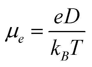
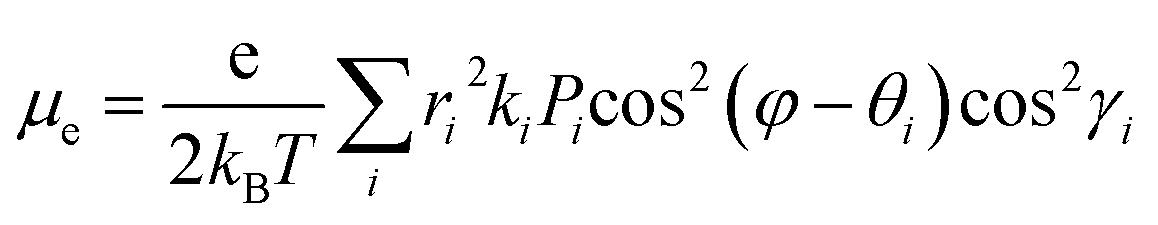
According to the hopping model, for perfect single crystals, the hopping electron mobility (μe) is calculated by using the Einstein relation in eqn (2),61
| |  | (2) |
where
e is the electronic charge and
D is the diffusion coefficient that is calculated from
eqn (3),
62| |  | (3) |
where
i stands for the various types of dimers that exist around one chosen monomer extracted from single crystals,
ri is the hopping distance,
θi is the angle between the hopping path of the dimer and the reference axis,
γi is the angle between the adjacent molecule and the plane of interest,
ki is the charge-hopping rate,
φ is the orientation angle of the transport channel relative to the reference axis and
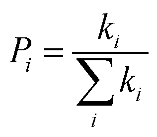
Pi is the hopping probability, which is calculated using
eqn (4),
63| |  | (4) |
Therefore,
μe can be given as
eqn (5),
| |  | (5) |
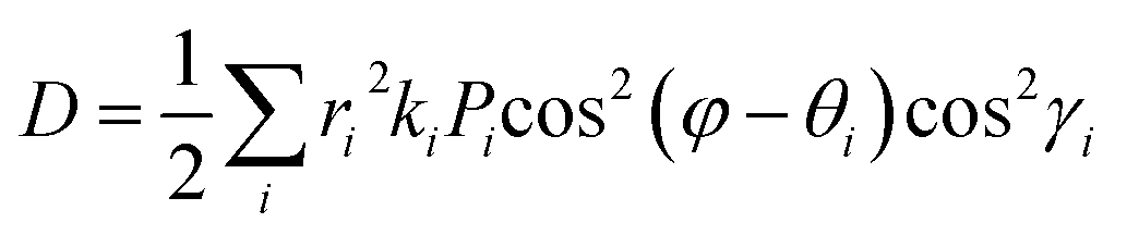
Since the molecular packing of BTPO-c is less symmetric in the direction of π-orbital stacking, the ac plane is taken as the reference plane and the
c axis is chosen as the reference axis (
Fig. 8a). For BTPO-z, the ab plane is chosen as the plane of interest, while for BTPO-l, the ac plane is investigated. For these two molecules, the direction of π-orbital stacking is fixed as the reference axis for theoretical calculation (
Fig. 8b and c). As the reference plane and axis are fixed, the corresponding
r,
θ and
γ values of every dimer in BTPO-c, BTPO-z and BTPO-l are summarized in Table S5.
† Based on
eqn (5), the corresponding simulated anisotropic electron mobility curves can be drawn, as shown in
Fig. 5. All three single crystals exhibit apparent anisotropic electron transport properties. For instance, BTPO-z achieves the highest electron mobility of 5.765 cm
2 V
−1 s
−1 as the transport channel angle (
φ) is 79.1°/259.1°. This direction is the same as the hopping direction of s2. The lowest electron mobility is 0.0003 cm
2 V
−1 s
−1 as
φ is 169.1°/349.1°. Although larger maximum electron mobilities are observed for BTPO-c and BTPO-z, the minimum electron mobility of BTPO-l significantly outperforms those of the other two heteroarenes (0.053 cm
2 V
−1 s
−1 for BTPO-l; 0.015 cm
2 V
−1 s
−1 for BTPO-c and 0.0003 cm
2 V
−1 s
−1 for BTPO-z). Note that many factors such as device fabrication conditions, impurities of materials and traps at the interface between the active layer and the gate are all ignored during the calculation process. However, the above factors have a significant influence on the practical OFET performance.
64–66 Besides, the calculation mechanism is based on Marcus theory, which sometimes has limitations for high-mobility organic semiconductors with the band-like transport process.
67–69 Therefore, theoretical calculations here can only elucidate the possible transport processes and give out some reference values.
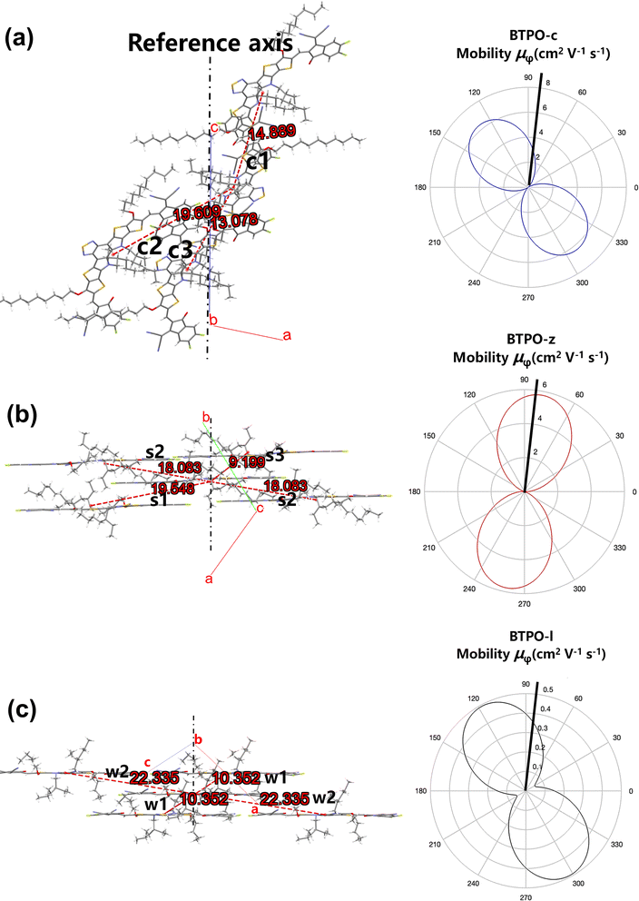 |
| | Fig. 8 (a–c) Molecular packing viewed along the normal to the plane of interest (left: the number in green stands for the hoping distance (r, Å)) and corresponding simulated anisotropic electron mobility curves based on the hopping model (right) of (a) BTPO-c, (b) BTPO-z and (c) BTPO-l. | |
2.7. Single-crystal organic field-effect transistors
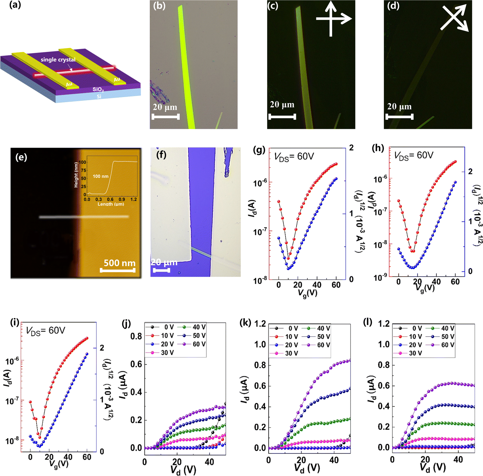
To investigate the relationship between single-crystal structures and electron transport properties, the BTPO-c, BTPO-z and BTPO-l single crystals were used to fabricate SC-OFET devices with a bottom gate/top contact (BGTC) structure (Fig. 9a). The micrometer-sized single crystals for fabricating SC-OFETs were obtained by drop casting 20 μL of 0.5 mg mL−1 BTPO-c, BTPO-z or BTPO-l in o-dichlorobenzene on an octadecyltrichlorosilane (OTS)-modified Si/SiO2 substrate and placed in an undisturbed environment (N2-filled glovebox). The quality of crystals was checked by optical microscopy (OM) and polarized optical microscopy (POM). Three crystals exhibit different shapes and sizes due to their disparate crystal-packing modes. Slender needle shaped crystallites of BTPO-c are formed with a crystal length of ∼40 μm (Fig. S7a†). On the other hand, BTPO-z possesses a rhomboid crystal with a smaller length of ∼30 μm and a larger width of ∼10 μm (Fig. S7d†). Excitingly, the crystal length of BTPO-l is the largest at ∼100 μm with a long strip-shaped crystal (Fig. 9b). Under POM, all three crystals display light/dark alteration when the polarizer and polarization analyzer are rotated by 45°, indicating the anisotropic nature of single crystals (Fig. 9c–d, S7b–c and e–f†). Besides, the thicknesses of the three single crystals were obtained by AFM, measuring ∼80 nm for BTPO-c and ∼100 nm for both BTPO-z and BTPO-l (Fig. 9e and S8†).
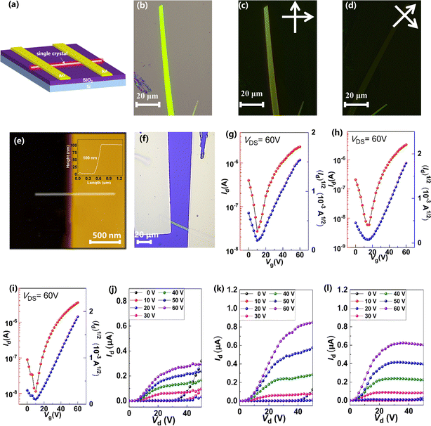 |
| | Fig. 9 (a) The device structure of the SC-OFETs; (b–d) OM and POM images of the single crystal of BTPO-l; (e) AFM image of the single crystal of BTPO-l; (f) optical microscopy images of the single crystal of BTPO-l on the SC-OFETs; (g–l) transfer curves and output curves of OFETs based on single crystals of (g and j) BTPO-c, (h and k) BTPO-z, and (i and l) BTPO-l, respectively. | |
The OM images, corresponding transfer and output curves of SC-OFETs based on BTPO-c, BTPO-z and BTPO-l are illustrated in Fig. 9f–l and S9† with the key parameters summarized in Table 2. All three single crystals exhibit n-type dominant charge transporting properties and their electron mobilities are all much higher than those of the corresponding thin-film OFETs, resulting from the more well-organized molecular packing in single crystals. Note that with the structure of BGTC, the hole carrier is inevitably injected, leading to a marginal hole mobility and relatively high off current. However, this hole mobility is very small (on the order of 10−4 to 10−5 cm2 V−1 s−1). For BTPO-c-based SC-OFETs, an electron mobility of 1.9 cm2 V−1 s−1 can be obtained, which is similar to those of previously reported parent BTP heteroarenes.18,52 On the other hand, SC-OFETs based on BTPO-z achieve a lower electron mobility of 0.6 cm2 V−1 s−1, which could be due to its loose packing motifs with a larger π–π stacking distance of 3.42–3.53 Å. Note that the experimental electron mobilities of BTPO-c and BTPO-z are in the range of those simulated ones referring to the hopping model (Fig. 8 and Table S5†). To our delight, SC-OFETs based on BTPO-l achieve a much higher electron mobility of 3.5 cm2 V−1 s−1. This is due to its compact 2D-brickwork crystal structure, resulting from its quasi-linear conformation with a unique dimer packing structure and a short π–π stacking distance of ∼3.30 Å. This mobility is not only the highest value among the three heteroarenes, but also outperforms those of all the other reported BTP-series heteroarenes. The experimental mobilities of BTPO-l are much higher than those of simulated ones (referring to the hopping model), providing a reverse proof that the carrier transport in BTPO-l is not aligned with the hopping mechanism but rather resembles a band-like transport process. In fact, the band-like transport process is often observed in organic semiconductors with a 2D brickwork structure.70–72
Table 2 The OFET characteristics based on the three single crystals
| Heteroarenes |
μ
e max (cm2 V−1 s−1)a |
μ
e avg (cm2 V−1 s−1)b |
V
th (V) |
I
on/Ioff ratio |
|
Maximum values of the electron mobilities.
The average values are calculated from >10 devices.
|
| BTPO-c |
1.9 |
0.7 |
3–15 |
102–103 |
| BTPO-z |
0.6 |
0.4 |
10–21 |
101–102 |
| BTPO-l |
3.5 |
1.4 |
9–12 |
102–103 |
3 Conclusion
In summary, we report a new strategy to control the crystal structures of heteroarenes for superior charge transport. Based on the parent BTPO-c with a banana conformation, two new derivatives named BTPO-z and BTPO-l have been synthesized by shortening the length of central cores from heptacyclic to hexacyclic and pentacyclic. BTPO-z shows an angular conformation, while BTPO-l demonstrates a quasi-linear conformation. By controlling the molecular conformation, we are able to tailor the molecular packing motifs and electron transport properties. Importantly, it is found that the single crystal of BTPO-c prefers to form a 3D interpenetrating porous network, while a compact 2D-brickwork structure is found in the single crystals of BTPO-l due to its linear molecular conformation. On the other hand, the longer length of conjugated central cores reduces the overlap of molecules in BTPO-z, making the molecular packing not as compact as that of BTPO-l. As a result, SC-OFETs based on BTPO-l display a remarkable electron mobility of 3.5 cm2 V−1 s−1, which is one of the highest performances among the electron-deficient heteroarenes. Our work provides a new idea for controlling the crystal structure of n-type heteroarenes for high-performance organic semiconductors.
Data availability
CCDC 2244244, 2254615 and 2255233 contain the supplementary crystallographic data for BTPO-l, BTPO-z and BTPO-c, respectively. These data can be obtained free of charge from the Cambridge Crystallographic Data Centre viahttps://www.ccdc.cam.ac.uk/structures/. The data supporting this article have been included as part of the ESI.†
Author contributions
Conceptualization: Y. C. and Y.·W.; methodology: Y.·C., Z. W., and Y.·W.; investigation: Y.·C., Z. W., Z. C., S. Z., W. L., and Y.·W.; formal analysis: Y.·C., Z. W., and Y.·W.; funding acquisition: Y.·C., Y. Z, Y.·W., and Y. L.; resources: Y. Z., Y. L., and Y.·W.; writing original draft: Y. C. and Y.·W.; writing – review and editing: all authors; supervision: Y.·W.
Conflicts of interest
The authors declare no conflict of interest.
Acknowledgements
We are grateful for financial support from the National Natural Science Foundation of China (Grant No. 22375051 and 52203216) and the Natural Science Foundation of Shanghai Municipality (21ZR1406900). Y.C. acknowledges the financial support from the Postdoctoral Research Foundation of China (2022M720756 and YJ20210249). The authors thank the beamline 15U of the Shanghai Synchrotron Radiation Facility for providing the beam time and assistance during experiments. The authors also would like to thank the Shiyanjia Lab (http://www.shiyanjia.com) for the MALDI-ToF measurements.
Notes and references
- S. Fratini, M. Nikolka, A. Salleo, G. Schweicher and H. Sirringhaus, Nat. Mater., 2020, 19, 491–502 CrossRef CAS PubMed.
- Z. Chen, J. Li, J. Wang, K. Yang, J. Zhang, Y. Wang, K. Feng, B. Li, Z. Wei and X. Guo, Angew. Chem., Int. Ed., 2022, 61, e202205315 CrossRef CAS PubMed.
- L. Wang, Z. Yi, Y. Zhao, Y. Liu and S. Wang, Chem. Soc. Rev., 2023, 52, 795–835 RSC.
- Y. Wang, T. Hasegawa, H. Matsumoto and T. Michinobu, J. Am. Chem. Soc., 2019, 141, 3566–3575 CrossRef CAS PubMed.
- J. Li, Z. Chen, J. Wang, S. Young Jeong, K. Yang, K. Feng, J. Yang, B. Liu, H. Y. Woo and X. Guo, Angew. Chem., Int. Ed., 2023, 62, e202307647 CrossRef CAS PubMed.
- J. Yi, G. Zhang, H. Yu and H. Yan, Nat. Rev. Mater., 2024, 9, 46–62 CrossRef CAS.
- J. Wang, P. Xue, Y. Jiang, Y. Huo and X. Zhan, Nat. Rev. Chem, 2022, 6, 614–634 CrossRef PubMed.
- J. Luke, E. J. Yang, C. Labanti, S. Y. Park and J.-S. Kim, Nat. Rev. Mater., 2023, 8, 839–852 CrossRef CAS.
- S. Ma, B. Li, S. Gong, J. Wang, B. Liu, S. Young Jeong, X. Chen, H. Young Woo, K. Feng and X. Guo, Angew. Chem., Int. Ed., 2023, 62, e202308306 CrossRef CAS PubMed.
- J. Rivnay, S. Inal, A. Salleo, R. M. Owens, M. Berggren and G. G. Malliaras, Nat. Rev. Mater., 2018, 3, 17086 CrossRef CAS.
- K. Feng, W. Shan, J. Wang, J.-W. Lee, W. Yang, W. Wu, Y. Wang, B. J. Kim, X. Guo and H. Guo, Adv. Mater., 2022, 34, 2201340 CrossRef CAS.
- P. Li, J. Shi, Y. Lei, Z. Huang and T. Lei, Nat. Commun., 2022, 13, 5970 CrossRef PubMed.
- Y. Wang and Y. Liu, Trends Chem., 2023, 5, 279–294 CrossRef CAS.
- K.-K. Liu, P. Li, Y. Lei, Z. Zhang, X. Pan, S. K. So and T. Lei, Adv. Funct. Mater., 2023, 33, 2300049 CrossRef CAS.
- J. Yuan, Y. Zhang, L. Zhou, G. Zhang, H.-L. Yip, T.-K. Lau, X. Lu, C. Zhu, H. Peng, P. A. Johnson, M. Leclerc, Y. Cao, J. Ulanski, Y. Li and Y. Zou, Joule, 2019, 3, 1140–1151 CrossRef CAS.
- S. Liu, J. Yuan, W. Deng, M. Luo, Y. Xie, Q. Liang, Y. Zou, Z. He, H. Wu and Y. Cao, Nat. Photonics, 2020, 14, 300–305 CrossRef CAS.
- L. Liu, Z. Wei and S. C. J. Meskers, Adv. Mater., 2023, 35, 2209730 CrossRef CAS PubMed.
- C. Xiao, C. Li, F. Liu, L. Zhang and W. Li, J. Mater. Chem. C, 2020, 8, 5370–5374 RSC.
- I. Vladimirov, M. Kellermeier, T. Geßner, Z. Molla, S. Grigorian, U. Pietsch, L. S. Schaffroth, M. Kühn, F. May and R. T. Weitz, Nano Lett., 2018, 18, 9–14 CrossRef CAS PubMed.
- Y. Zhang, Y. Wang, C. Gao, Z. Ni, X. Zhang, W. Hu and H. Dong, Chem. Soc. Rev., 2023, 52, 1331–1381 RSC.
- Y. Wang, T. Hasegawa, H. Matsumoto and T. Michinobu, Angew. Chem., Int. Ed., 2019, 58, 11893–11902 CrossRef CAS PubMed.
- Y. Chen, Z. Wu, Z. Chen, S. Zhang, Z. Jiang, W. Li, Y. Zhao, Y. Wang and Y. Liu, Chem. Eng. J., 2024, 485, 149536 CrossRef CAS.
- L. Ding, Z.-D. Yu, X.-Y. Wang, Z.-F. Yao, Y. Lu, C.-Y. Yang, J.-Y. Wang and J. Pei, Chem. Rev., 2023, 123, 7421–7497 CrossRef CAS PubMed.
- D. Liu, Y. Zhao, J. Zhang, Z. Wei, Y. Liu and Y. Wang, Angew. Chem., Int. Ed., 2024, 63, e202400061 CrossRef CAS.
- H. Li, W. Shi, J. Song, H.-J. Jang, J. Dailey, J. Yu and H. E. Katz, Chem. Rev., 2019, 119, 3–35 CrossRef CAS.
- S. Zhang, W. Li, Y. Chen, Z. Wu, Z. Chen, Y. Zhao, Y. Wang and Y. Liu, Chem. Commun., 2023, 59, 9876–9879 RSC.
- G.-Y. Ge, J.-T. Li, J.-R. Wang, M. Xiong, X. Dong, Z.-J. Li, J.-L. Li, X.-Y. Cao, T. Lei and J.-L. Wang, Adv. Funct. Mater., 2022, 32, 2108289 CrossRef CAS.
- J. E. Anthony, Chem. Rev., 2006, 106, 5028–5048 CrossRef CAS PubMed.
- U. H. F. Bunz, Acc. Chem. Res., 2015, 48, 1676–1686 CrossRef CAS PubMed.
- S. Kumagai, H. Ishii, G. Watanabe, C. P. Yu, S. Watanabe, J. Takeya and T. Okamoto, Acc. Chem. Res., 2022, 55, 660–672 CrossRef CAS.
- Z. Wu, W. Liu, X. Yang, W. Li, L. Zhao, K. Chi, X. Xiao, Y. Yan, W. Zeng, Y. Liu, H. Chen and Y. Zhao, Angew. Chem., Int. Ed., 2023, 62, e202307695 CrossRef CAS PubMed.
- M. Chu, J.-X. Fan, S. Yang, D. Liu, C. F. Ng, H. Dong, A.-M. Ren and Q. Miao, Adv. Mater., 2018, 30, 1803467 CrossRef PubMed.
- K. Takimiya, K. Bulgarevich, M. Abbas, S. Horiuchi, T. Ogaki, K. Kawabata and A. Ablat, Adv. Mater., 2021, 33, 2102914 CrossRef CAS PubMed.
- G. Zhang, X.-K. Chen, J. Xiao, P. C. Y. Chow, M. Ren, G. Kupgan, X. Jiao, C. C. S. Chan, X. Du, R. Xia, Z. Chen, J. Yuan, Y. Zhang, S. Zhang, Y. Liu, Y. Zou, H. Yan, K. S. Wong, V. Coropceanu, N. Li, C. J. Brabec, J.-L. Bredas, H.-L. Yip and Y. Cao, Nat. Commun., 2020, 11, 3943 CrossRef CAS PubMed.
- A. Khasbaatar, Z. Xu, J.-H. Lee, G. Campillo-Alvarado, C. Hwang, B. N. Onusaitis and Y. Diao, Chem. Rev., 2023, 123, 8395–8487 CrossRef CAS PubMed.
- Z. Zhou, W. Liu, G. Zhou, M. Zhang, D. Qian, J. Zhang, S. Chen, S. Xu, C. Yang, F. Gao, H. Zhu, F. Liu and X. Zhu, Adv. Mater., 2020, 32, 1906324 CrossRef CAS.
- Z. Luo, R. Ma, T. Liu, J. Yu, Y. Xiao, R. Sun, G. Xie, J. Yuan, Y. Chen, K. Chen, G. Chai, H. Sun, J. Min, J. Zhang, Y. Zou, C. Yang, X. Lu, F. Gao and H. Yan, Joule, 2020, 4, 1236–1247 CrossRef CAS.
- Y. Cui, H. Yao, J. Zhang, T. Zhang, Y. Wang, L. Hong, K. Xian, B. Xu, S. Zhang, J. Peng, Z. Wei, F. Gao and J. Hou, Nat. Commun., 2019, 10, 2515 CrossRef PubMed.
- Y. Chen, R. Ma, T. Liu, Y. Xiao, H. K. Kim, J. Zhang, C. Ma, H. Sun, F. Bai, X. Guo, K. S. Wong, X. Lu and H. Yan, Adv. Energy Mater., 2021, 11, 2003777 CrossRef CAS.
- Y. Chen, Y. Chang, R. Ma, H. Liu, J. Yi, J. Zhang, T. Liu, Z. Qi, K. Yu, X. Lu, H. Hu and H. Yan, Chem. Eng. J., 2022, 441, 135998 CrossRef CAS.
- F. Lin, K. Jiang, W. Kaminsky, Z. Zhu and A. K. Y. Jen, J. Am. Chem. Soc., 2020, 142, 15246–15251 CrossRef CAS PubMed.
- L. Wang, Q. An, L. Yan, H.-R. Bai, M. Jiang, A. Mahmood, C. Yang, H. Zhi and J.-L. Wang, Energy Environ. Sci., 2022, 15, 320–333 RSC.
- C. Li, J. Zhou, J. Song, J. Xu, H. Zhang, X. Zhang, J. Guo, L. Zhu, D. Wei, G. Han, J. Min, Y. Zhang, Z. Xie, Y. Yi, H. Yan, F. Gao, F. Liu and Y. Sun, Nat. Energy, 2021, 6, 605–613 CrossRef CAS.
- Y. Zou, H. Chen, X. Bi, X. Xu, H. Wang, M. Lin, Z. Ma, M. Zhang, C. Li, X. Wan, G. Long, Y. Zhaoyang and Y. Chen, Energy Environ. Sci., 2022, 15, 3519–3533 RSC.
- A. Kieliszek and M. Malinska, Cryst. Growth Des., 2021, 21, 6862–6871 CrossRef CAS.
- Y. Chen, F. Bai, Z. Peng, L. Zhu, J. Zhang, X. Zou, Y. Qin, H. K. Kim, J. Yuan, L.-K. Ma, J. Zhang, H. Yu, P. C. Y. Chow, F. Huang, Y. Zou, H. Ade, F. Liu and H. Yan, Adv. Energy Mater., 2021, 11, 2003141 CrossRef CAS.
- Y. Chen, T. Liu, L.-K. Ma, W. Xue, R. Ma, J. Zhang, C. Ma, H. K. Kim, H. Yu, F. Bai, K. S. Wong, W. Ma, H. Yan and Y. Zou, J. Mater. Chem. A, 2021, 9, 7481–7490 RSC.
- P. Müller-Buschbaum, Adv. Mater., 2014, 26, 7692–7709 CrossRef PubMed.
- Y. Chen, T. Liu, H. Hu, T. Ma, J. Y. L. Lai, J. Zhang, H. Ade and H. Yan, Adv. Energy Mater., 2018, 8, 1801203 CrossRef.
- Y. Xiao and X. Lu, Mater. Today Nano, 2019, 5, 100030 CrossRef.
- T. Shen, W. Li, Y. Zhao, Y. Wang and Y. Liu, Adv. Mater., 2023, 35, 2210093 CrossRef CAS PubMed.
- Y. Chen, Z. Wu, L. Ding, S. Zhang, Z. Chen, W. Li, Y. Zhao, Y. Wang and Y. Liu, Adv. Funct. Mater., 2023, 33, 2304316 CrossRef CAS.
- Y. Qiu, B. Zhang, J. Yang, H. Gao, S. Li, L. Wang, P. Wu, Y. Su, Y. Zhao, J. Feng, L. Jiang and Y. Wu, Nat. Commun., 2021, 12, 7038 CrossRef CAS PubMed.
- Q. Liu, Y. Wang, A. Kohara, H. Matsumoto, S. Manzhos, K. Feron, S. E. Bottle, J. Bell, T. Michinobu and P. Sonar, Adv. Funct. Mater., 2020, 30, 1907452 CrossRef CAS.
- Y. Wang and K. Takimiya, Adv. Mater., 2020, 32, 2002060 CrossRef PubMed.
- T. Shen, W. Li, Y. Zhao, Y. Liu and Y. Wang, Matter, 2022, 5, 1953–1968 CrossRef CAS.
- Q. Liu, Y. Wang, Y. Ren, A. Kohara, H. Matsumoto, Y. Chen, S. Manzhos, K. Feron, S. E. Bottle, J. Bell, Y. Zhou, T. Michinobu and P. Sonar, ACS Appl. Electron. Mater., 2020, 2, 1609–1618 CrossRef CAS.
- X. Zhang, C. Li, J. Xu, R. Wang, J. Song, H. Zhang, Y. Li, Y.-N. Jing, S. Li, G. Wu, J. Zhou, X. Li, Y. Zhang, X. Li, J. Zhang, C. Zhang, H. Zhou, Y. Sun and Y. Zhang, Joule, 2022, 6, 444–457 CrossRef CAS.
- Y. Liu, Y. Wang, L. Ai, Z. Liu, X. Ouyang and Z. Ge, Dyes Pigm., 2015, 121, 363–371 CrossRef CAS.
- K. Patrikar, N. Jain, D. Chakraborty, P. Johari, V. R. Rao and D. Kabra, Adv. Funct. Mater., 2019, 29, 1805878 CrossRef.
- S. Wen, W.-Q. Deng and K.-L. Han, Chem. Commun., 2010, 46, 5133–5135 RSC.
- W.-Q. Deng, L. Sun, J.-D. Huang, S. Chai, S.-H. Wen and K.-L. Han, Nat. Protoc., 2015, 10, 632–642 CrossRef CAS PubMed.
- S. W. Kim, Y. Wang, H. You, W. Lee, T. Michinobu and B. J. Kim, ACS Appl. Mater. Interfaces, 2019, 11, 35896–35903 CrossRef CAS PubMed.
- L. Lin, H. Geng, Z. Shuai and Y. Luo, Org. Electron., 2012, 13, 2763–2772 CrossRef CAS.
- Z. Shuai, H. Geng, W. Xu, Y. Liao and J.-M. André, Chem. Soc. Rev., 2014, 43, 2662–2679 RSC.
- H. Geng, Q. Peng, L. Wang, H. Li, Y. Liao, Z. Ma and Z. Shuai, Adv. Mater., 2012, 24, 3568–3572 CrossRef CAS PubMed.
- C. Liu, K. Huang, W.-T. Park, M. Li, T. Yang, X. Liu, L. Liang, T. Minari and Y.-Y. Noh, Mater. Horiz., 2017, 4, 608–618 RSC.
- H. Oberhofer, K. Reuter and J. Blumberger, Chem. Rev., 2017, 117, 10319–10357 CrossRef CAS PubMed.
- Y. Shi, W. Li, X. Wang, L. Tu, M. Li, Y. Zhao, Y. Wang and Y. Liu, Chem. Mater., 2022, 34, 1403–1413 CrossRef CAS.
- T. Okamoto, S. Kumagai, E. Fukuzaki, H. Ishii, G. Watanabe, N. Niitsu, T. Annaka, M. Yamagishi, Y. Tani, H. Sugiura, T. Watanabe, S. Watanabe and J. Takeya, Sci. Adv., 2020, 6, eaaz0632 CrossRef CAS PubMed.
- K. Bulgarevich, S. Horiuchi and K. Takimiya, Adv. Mater., 2023, 35, 2305548 CrossRef CAS PubMed.
- K. Bulgarevich, S. Horiuchi, T. Ogaki and K. Takimiya, Chem. Mater., 2022, 34, 6606–6616 CrossRef CAS.
|
| This journal is © The Royal Society of Chemistry 2024 |
Click here to see how this site uses Cookies. View our privacy policy here. 
 Open Access Article
 This Open Access Article is licensed under a Creative Commons Attribution-Non Commercial 3.0 Unported Licence
 * and
Yunqi
Liu
* and
Yunqi
Liu