
 Open Access Article
 This Open Access Article is licensed under a Creative Commons Attribution-Non Commercial 3.0 Unported Licence
Kinetically controlled synthesis of low-strain disordered micro–nano high voltage spinel cathodes with exposed {111} facets†
Zhi-Qi Liab,
Yi-Feng Liuab,
Han-Xiao Liuab,
Yan-Fang Zhu*ab,
Jingqiang Wang ab,
Mengke Zhangc,
Lang Qiu*c,
Xiao-Dong Guoc,
Shu-Lei Chou*ab and
Yao Xiao*abd
ab,
Mengke Zhangc,
Lang Qiu*c,
Xiao-Dong Guoc,
Shu-Lei Chou*ab and
Yao Xiao*abd
aCollege of Chemistry and Materials Engineering, Wenzhou University, Wenzhou, 325035, P. R. China. E-mail: yanfangzhu@wzu.edu.cn; chou@wzu.edu.cn; xiaoyao@wzu.edu.cn
bWenzhou Key Laboratory of Sodium-Ion Batteries, Wenzhou University Technology Innovation Institute for Carbon Neutralization, Wenzhou, 325035, P. R. China
cCollege of Chemical Engineering, Sichuan University, Chengdu, 610065, P. R. China. E-mail: qiulang2023@scu.edu.cn
dKey Laboratory of Advanced Energy Materials Chemistry (Ministry of Education), Nankai University, Tianjin 300071, P. R. China
First published on 13th June 2024
Abstract
High-voltage LiNi0.5Mn1.5O4 (LNMO) is one of the most promising cathode candidates for rechargeable lithium-ion batteries (LIBs) but suffers from deteriorated cycling stability due to severe interfacial side reactions and manganese dissolution. Herein, a micro–nano porous spherical LNMO cathode was designed for high-performance LIBs. The disordered structure and the preferred exposure of the {111} facets can be controlled by the release of lattice oxygen in the high-temperature calcination process. The unique configuration of this material could enhance the structural stability and play a crucial role in inhibiting manganese dissolution, promoting the rapid transport of Li+, and reducing the volume strain during the charge/discharge process. The designed cathode exhibits a remarkable discharge capacity of 136.7 mA h g−1 at 0.5C, corresponding to an energy density of up to 636.4 W h kg−1, unprecedented cycling stability (capacity retention of 90.6% after 500 cycles) and superior rate capability (78.9% of initial capacity at 10C). The structurally controllable preparation strategy demonstrated in this work provides new insights into the structural design of cathode materials for LIBs.
1. Introduction
Lithium-ion batteries (LIBs), a well-established and efficient energy storage technology, have received much attention for realizing renewable energy utilization.1–5 The increasing popularity of electric vehicles has sparked a rising demand for energy density in rechargeable batteries.6 The spinel LiNi0.5Mn1.5O4 (LNMO) cathode with high working voltage over 4.7 V vs. Li/Li+ and its 3D Li+ diffusion paths has the potential to be used in next-generation fast-charge LIBs with high energy density.7–9 Nevertheless, its high-voltage operating conditions tend to cause various issues, including structural decay due to the dissolution of transition metal (TM) ions and parasitic side reactions at the electrode/electrolyte interface, which result in rapid performance degradation.10–14To improve the performance of LNMO, many strategies have been developed including surface modification, elemental doping and structural optimization.15–19 Rational geometrical design is important to improve the performance of cathode materials; therefore, it has attracted extensive attention.20–23 On the one hand, nanostructured materials can shorten the transport path of Li+ and increase the contact area between the electrolyte and electrode, resulting in excellent rate performance.24–28 On the other hand, micrometer structured materials offer high compaction density and minimized side reactions with electrolytes. Meanwhile, designing micro–nano hierarchical structure materials can preserve the characteristics of nanostructures and combine the advantages of micrometer structures.29–32 Besides, the crystal facets of the LNMO also affect its electrochemical performance. Previous studies have shown that choosing crystal facets with lower surface energy can help stabilize the crystal structure and reduce the occurrence of interfacial side reactions.33–35 Crystal facets with high surface energy become unstable, and controlling their growth helps to stabilize the crystals. Among the predominant crystallographic facets, the {111} facets improve electrochemical performance due to their low surface energy and quick Li+ intercalation/deintercalation. Additionally, the porous cathode material area enhances the utilization of the active electrode material. The presence of pores also facilitates ion diffusion and transport, thereby enhancing electrochemical performance.36 In terms of the above research, designing micro–nano hierarchical LNMO porous spherical particles with exposed stable {111} facets can achieve outstanding rate performance, cycling stability, and high energy density.37–40 Nevertheless, the issue of accurately controlling the design of these composite structures remains unresolved.
Herein, we precisely design micro–nano hierarchical LNMO porous spherical particles with exposed {111} facets via a carbonate co-precipitation method combined with high-temperature calcination. By controlling the decomposition kinetics, the loss of lattice oxygen can be regulated, thereby precisely adjusting the disordered structure and giving preference to exposing {111} facets. This material is a secondary spherical particle formed by stacking multiple octahedral primary particles, and voids are formed inside the particles due to the release of internal CO2. This unique structure inhibits crystal structure decay, enhances Li+ migration, and alleviates the dissolution of TM ions. Through the integration of advanced structural characterization techniques, including high-angle annular dark-field scanning transmission electron microscopy (HAADF-STEM) achieved using spherical aberration-corrected electron microscopy, bright points in the annular bright-field scanning transmission electron microscopy (ABF-STEM), and high-resolution transmission electron microscopy, the special structure of the designed material was confirmed, and its superior electrochemical performance and structural stability were elucidated through the electrochemical system and high temperature in situ X-ray diffraction. The designed LNMO cathode exhibits excellent cycling stability and still has a 90.6% capacity retention rate after 500 cycles at 1C. It shows excellent rate performance, with a significant discharge capacity of 107.86 mA h g−1 at 10C. The designed LNMO cathode exhibited exceptional rate capability and unprecedented long-term cycling stability, showcasing its promise for practical applications in high-performance LIBs. These findings offer valuable insights for future studies on accurately controlling crystal growth to create high-performance cathodes.
2. Results and discussion
2.1. The formation process of LiNi0.5Mn1.5O4 (LNMO)
The Ni0.5Mn1.5CO3 precursor has been obtained through carbonate co-precipitation, and the synthesis method is in the ESI.† X-ray diffraction (XRD) revealed the structural features of the Ni0.25Mn0.75CO3 precursor and the diffraction peaks of the precursors were identified as hexagonal carbonate structures with the R![[3 with combining macron]](https://www.rsc.org/images/entities/char_0033_0304.gif) c space group (Fig. 1a).41 Scanning electron microscopy (SEM) and transmission electron microscopy (TEM) tests were also carried out to observe the morphology of the precursors. The results showed that the precursor exhibited a spherical shape with most of the particles being around 3–5 μm (Fig. 1b, c and S1†). Moreover, to understand the structural changes in the formation of the LNMO cathode, the precursor was analyzed using high temperature in situ XRD. Upon analysis, it was found that as the temperature increased to 400 °C, the peaks (012), (104), and (116) in the precursor gradually disappeared, while the peak (111) began to emerge. During the temperature increase to 850 °C and the subsequent cooling process, a noticeable increase in the intensity of the (111) peak was observed compared to the (311) peak. This observation suggested a preference for the exposure of {111} facets during the materials' formation process. Furthermore, with the temperature raised to 900 °C and the material held at this temperature, the level of crystallinity exhibited a progressive increase (Fig. 1d, e, S2 and S3†). The decomposition process of the LNMO cathode was verified using thermogravimetric (TG) curves (Fig. S4†). Initially, 5.1% weight loss from room temperature to around 230 °C was observed, which was attributed to the removal of hydrate water. Subsequently, a significant weight loss of 28.6% was identified, related to the thermal decomposition of MnCO3 and the lithiation process. Interestingly, the TG test displayed a slight loss in quality above 800 °C, indicating the release of lattice oxygen. In particular, this situation would cause migration of TM ions and structural reconstruction, forming a disordered spinel phase with the space group of Fdm. The morphological analysis conducted on the precursors at different temperatures found that the crystallinity of the precursors increases, the surface becomes smoother and the octahedral structure gradually forms as the temperature increases (Fig. S5†). Analysis of the crystal structures of Fdm and P4332 from the [100] and [111] axis showed that the Fdm space group exhibits higher symmetry than the P4332 space group (Fig. 1f–i). Furthermore, P4332 has a Mn valence of +4, while Fdm contains traces of Mn3+. The presence of Mn3+ in the Fdm structure of LNMO increases the electronic conductivity, which is typically 2.5 orders of magnitude larger than that in the Fdm structure than in the P4332 structure. Due to this difference, Li+ diffusion in Fdm spinel is faster than that of P4332.42,43
c space group (Fig. 1a).41 Scanning electron microscopy (SEM) and transmission electron microscopy (TEM) tests were also carried out to observe the morphology of the precursors. The results showed that the precursor exhibited a spherical shape with most of the particles being around 3–5 μm (Fig. 1b, c and S1†). Moreover, to understand the structural changes in the formation of the LNMO cathode, the precursor was analyzed using high temperature in situ XRD. Upon analysis, it was found that as the temperature increased to 400 °C, the peaks (012), (104), and (116) in the precursor gradually disappeared, while the peak (111) began to emerge. During the temperature increase to 850 °C and the subsequent cooling process, a noticeable increase in the intensity of the (111) peak was observed compared to the (311) peak. This observation suggested a preference for the exposure of {111} facets during the materials' formation process. Furthermore, with the temperature raised to 900 °C and the material held at this temperature, the level of crystallinity exhibited a progressive increase (Fig. 1d, e, S2 and S3†). The decomposition process of the LNMO cathode was verified using thermogravimetric (TG) curves (Fig. S4†). Initially, 5.1% weight loss from room temperature to around 230 °C was observed, which was attributed to the removal of hydrate water. Subsequently, a significant weight loss of 28.6% was identified, related to the thermal decomposition of MnCO3 and the lithiation process. Interestingly, the TG test displayed a slight loss in quality above 800 °C, indicating the release of lattice oxygen. In particular, this situation would cause migration of TM ions and structural reconstruction, forming a disordered spinel phase with the space group of Fdm. The morphological analysis conducted on the precursors at different temperatures found that the crystallinity of the precursors increases, the surface becomes smoother and the octahedral structure gradually forms as the temperature increases (Fig. S5†). Analysis of the crystal structures of Fdm and P4332 from the [100] and [111] axis showed that the Fdm space group exhibits higher symmetry than the P4332 space group (Fig. 1f–i). Furthermore, P4332 has a Mn valence of +4, while Fdm contains traces of Mn3+. The presence of Mn3+ in the Fdm structure of LNMO increases the electronic conductivity, which is typically 2.5 orders of magnitude larger than that in the Fdm structure than in the P4332 structure. Due to this difference, Li+ diffusion in Fdm spinel is faster than that of P4332.42,43
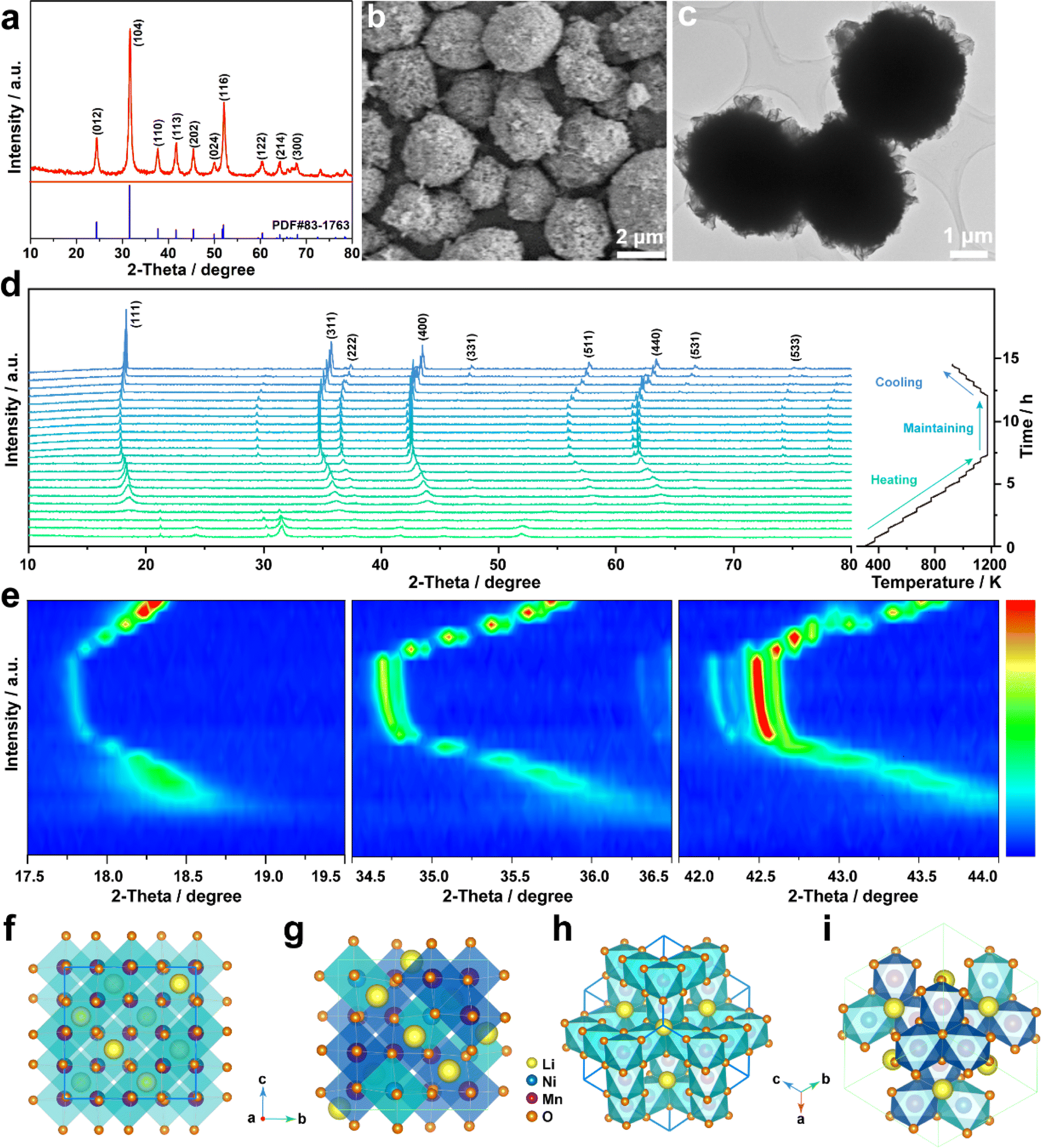 | ||
| Fig. 1 The structural evolution of the precursor. (a) Powder XRD pattern. (b) SEM image. (c) TEM image. (d) High temperature in situ XRD. (e) Contour maps of the corresponding area. (f) Fdm and (g) P4332 crystal structures viewed along the [100] axis. (h) Fdm and (i) P4332 crystal structures viewed along the [111] axis. | ||
2.2. Structural analysis of LNMO-111
In practical applications, the intermediate transformation involving the Fdm structure that occurs inside the P4332 structure will increase the strain and surface area impedance, resulting in a significant decrease in capacity. The electrochemical properties of the electrode with the Fdm structure are better than those of P4332, which prompts further research on the disordered structure of Fdm. For comprehensive consideration, the precursor is calcined at 900 °C for the synthesis of LiNi0.5Mn1.5O4 (denoted as LNMO-111). LNMO-111 exhibited good crystallinity as confirmed by XRD, showing diffraction peaks consistent with the spinel phase in the Fdm space group. It has been shown that the ratio of the (311) peak to the (400) peak reflects the crystallinity and structural stability of the material. In particular, the I(311)/I(400) ratios of LNMO-111 reduced to 0.96, compared to the normal reports of 1.10, suggesting that the material possesses good crystallinity and structural stability (Fig. 2a).44,45 And the calculated lattice parameter of LNMO-111 (a = 8.1726 Å) is close to that of standard LNMO (Fdm, a = 8.172 Å) (Table S1†).46 In the Fdm space group structure, Li is located at position 8a and diffuses along the 8a-16c pathway. Meanwhile, Ni and Mn are randomly situated at position 16d, and O is found at position 32e. In contrast, in the P4332 space group structure, Li is situated at position 8c and diffuses along the 8c-12d and 8c-4a pathways and Ni occupies position 4b, Mn is located at position 12d, and O is present at positions 8c and 24e. Compared with the P4332 structure, the Fdm structure showed a disordered structure (Fig. 2b and c).47,48 Additionally, LNMO-111 with disordered structures (Fdm) typically exhibited high {111} facet exposure.49,50 Notably, it was found by SEM that the primary particle of LNMO-111 with a disordered spinel structure shows a complete octahedron, and multiple octahedral particles are closely linked and aggregated into spheres. The proximity of particles enhances the transport of ions and electrons through the interface, which decreases stress accumulation and promotes uniform charge distribution within the secondary particles (Fig. 2d and e). The cross-section of LNMO-111 observed by focused ion beam scanning electron microscopy (FIB-SEM) revealed that the octahedral shapes are well maintained, and the cross-section exhibits a porous morphology, which is mainly attributed to the irregular arrangement of primary particles in micro–nano spherical particles (Fig. 2f and g).51 It is observed that there are also voids inside the cross-sections at different sites of LNMO-111 through the FIB test, which further proves the porous morphology of LNMO-111 (Fig. S6†). X-ray photoelectron spectroscopy (XPS) was used to examine the chemical composition and valence states. The Ni 2p XPS spectrum shows two distinct peaks corresponding to Ni 2p3/2 and Ni 2p1/2, respectively. The Mn 2p XPS spectrum reveals two distinct peaks corresponding to Mn 2p3/2 and Mn 2p1/2. The deconvolution of both the Mn 2p3/2 and Mn 2p1/2 regions demonstrates the presence of different chemical states of Mn. Specifically, the peaks at 641.2 eV and 642.7 eV in the Mn 2p3/2 spectrum are indicative of Mn3+ and Mn4+ states, respectively, while the peaks at 652.5 eV for Mn3+ and 654.2 eV for Mn4+ are observed in the Mn 2p1/2 spectrum. Furthermore, the O 1s XPS spectrum displays two major peaks, which are associated with the oxygen present in the M–O (M refers to the metal ion) bonds within the crystal lattice and with organic oxygen, respectively (Fig. S7†). Energy dispersive spectroscopy (EDS) mapping confirmed the homogeneous distribution of the elements Ni, Mn, and O in LNMO-111 (Fig. 2h–k).52 Besides, the atomic ratios of LNMO-111 were analyzed by EDS, demonstrating that the material composition is consistent with the theoretical design (Fig. S8†). The disordered structure of LNMO-111 can be analyzed by Raman spectroscopy. It can be observed through Raman spectroscopy that the highest band generated by the Mn–O tensile vibration has moved from 625 cm−1 to about 633 cm−1, which is due to the manganese valence being increased from +3.5 to +4. The bands at 491 cm−1 (F(2)2g) and 398 cm−1 (F1g) can be attributed to the Ni2+–O stretching mode in LNMO-111. In addition, the Raman peaks with the space group of P4332 are sharper and stronger and will split into two small peaks between 580 cm−1 and 610 cm−1. However, it can be observed from Fig. 2m that there is only one small peak of 590 cm−1 (F32g) within the above range, which proves that the space group of LNMO-111 is Fdm. The ratio of the intensities of the two bands near 621 cm−1 and 586 cm−1 shown by Fourier Transform Infrared Spectroscopy (FT-IR) can be used to qualitatively assess the degree of ordering of the spinel structure. Typically, the higher intensity of the band at 586 cm−1 and the lower intensity of the band at 621 cm−1 are attributed to the ordering of the Mn4+ and Ni2+; in this case, the lower intensity of the band at 586 cm−1 and the higher intensity of the band at 621 cm−1 suggest the presence of disordered Fdm phase in LNMO-111 (Fig. 2n). Previous research has indicated that there are three peaks of the P4332 space group near 646 cm−1, 464 cm−1, and 430 cm−1. However, these three peaks are not observed in Fig. 2n, which further proves that LNMO-111 is of the Fdm space group.53 Inductively coupled plasma-mass spectrometry (ICP-MS) was used to analyze the proportions of Li, Ni, and Mn elements of LNMO-111 and the result was consistent with the design principle (Table S2†).
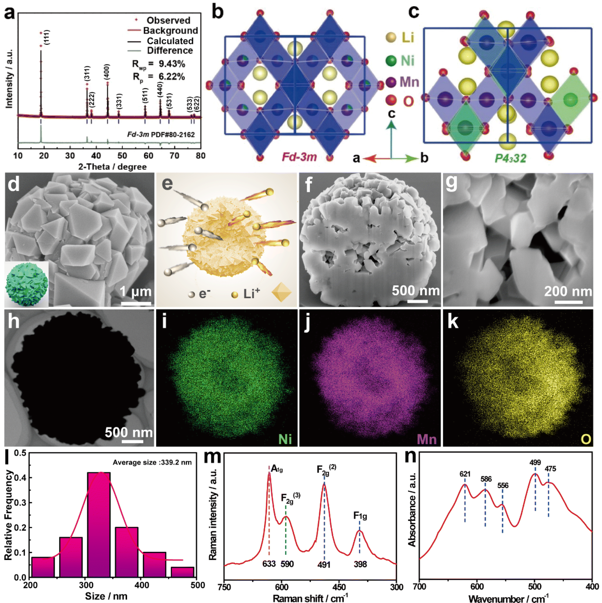 | ||
| Fig. 2 Structure of LNMO-111. (a) Powder XRD pattern and Rietveld refinement plot. (b) Fdm and (c) P4332 crystal structures viewed along the [110] axis. (d) SEM image. (e) Schematic diagram of Li+ and electron transport. (f and g) Cross-sectional SEM images by FIB. (h) TEM image and (i–k) EDS maps. (l) Size distribution. (m) Raman spectrum and (n) FT-IR spectra. | ||
2.3. Morphology and crystal orientation analysis of LNMO-111
The microstructure of LNMO-111 was observed by TEM and high-resolution TEM (HR-TEM) images. Fig. 3a shows that there is an obvious contrast between the inside and outside of the spheres, confirming the porous structure of LNMO-111. The controllable kinetics of lithiation and precursor decomposition can explain the formation of the porous spherical structure of LNMO-111. CO2 is quickly released from the inside, resulting in the precursor decomposition. This process leads to a hollow interior and a compact exterior of the particle. The cavities in each porous spherical particle can provide many additional active sites for Li+ storage, which is conducive to improving the specific capacity. Most importantly, the voids in the porous electrodes can buffer the local volume change during the charge/discharge process, which enhances the cycling performance. Moreover, Fig. 3b provided a partial magnification of the location delineated by the rectangle in Fig. 3a. The crystal structure of LNMO-111 was determined using the HR-TEM images, which show clear lattice fringes with a spacing of about 0.47 nm, well matched to the {111} facets of the spinel phase. Besides, the selected area electron diffraction (SAED) image in the inset in Fig. 3b further validates the structural compatibility of the material with the spinel structure. Upon analyzing the surface structure of LNMO-111, HR-TEM images and FFT patterns of various locations on randomly selected particles were scrutinized to confirm the preferential exposure of the {111} facets. The examination revealed clear lattice fringes in the HR-TEM images of different regions, with an interplanar spacing of about 0.47 nm, providing evidence that the {111} facets were indeed preferentially exposed (Fig. S9†).41 An atomic structure model of LNMO-111 has been developed along the [111] axis (Fig. 3c). HAADF-STEM and ABF-STEM images in Fig. 3d and e obtained through spherical aberration-corrected electron microscopy depicted the positions of the TM ions along the crystallographic direction. These positions are found to be in high agreement with the atomic model in Fig. 3f, aligning perfectly with spinel phases without any structural distortions. Moreover, the strong binding among LNMO-111 atoms can be observed through spherical aberration, and the increased stability of the material is attributed to its denser atomic arrangement resulting in lower surface energy. Through the analysis of high-resolution STEM images, line profiles, and FFT patterns, a typical spinel atomic arrangement is revealed, demonstrating the absence of any structural distortion (Fig. S10–S12†). These results show that the micro–nano hierarchical LNMO porous spherical particles with exposed stable {111} facets have been successfully prepared. | ||
| Fig. 3 Morphology structure analysis of LNMO-111. (a) TEM image. (b) HR-TEM image and SAED pattern. (c) Atomic structure viewed along the [111] axis. (d and e) Enlarged HAADF- and ABF-STEM image viewed along the [110] axis. (f) LNMO-111 crystal structures viewed along the [110] axis. | ||
2.4. Dynamic structural evolution of LNMO-111 during high-temperature sintering and its electrochemical performance
The structural evolution of LNMO-111 was monitored by high temperature in situ XRD during the process of gradually heating the sample from room temperature to 1200 K and cooling to room temperature at the same rate. As the sample is heated, it is observed that peaks such as (111), (311), (222), and (400) exhibit a leftward shift, indicating a gradual increase in the lattice parameters of LNMO-111.54,55 This shift was indicative of a structural transformation that aligns well with the spinel structure of LNMO-111 when calcined. Subsequently, the peak gradually returns to the initial position during the cooling process, indicating that the lattice parameter is restored to the pristine state; this suggests that LNMO-111 exhibits good reversible thermal stability (Fig. 4a, b and S13†). Furthermore, LNMO-111 offers a generous 3D channel that enhances fast Li+ transport, leading to superior rate performance. The galvanostatic charge and discharge curves generated with half-cells containing the LNMO-111 cathode exhibit clear flat plateaus around 4.60–4.80 V and deliver an excellent discharge specific capacity of 136.7 mA h g−1 at 0.5C (Fig. 4c). The performance of the material was evaluated by subjecting it to various current densities ranging from 0.5 to 10C. The micro–nano hierarchical LNMO-111 cathode demonstrates a stable discharge capacity at each current density and achieves a capacity of 107.88 mA h g−1 at 10C, indicating exceptional performance (Fig. 4d). The CV curves clearly show three redox peaks. The 4.0 V potential plateau corresponds to Mn3+ oxidizing to Mn4+, showing that the obtained LNMO-111 has the Fdm structure. Two pairs of redox peaks at 4.78/4.57 V and 4.83/4.68 V correspond to the oxidation/reduction reactions of Ni2+/Ni3+ and Ni3+/Ni4+, respectively. The redox reactions of Ni2+/Ni3+ and Ni3+/Ni4+ yield anodic and cathodic current peaks with potential differences of 0.21 V and 0.15 V, respectively. These values suggest rapid Li+ intercalation/deintercalation kinetics. Additionally, small redox current peaks at approximately 4.0 V can be attributed to the redox reaction of Mn3+/Mn4+ (Fig. 4e). Notably, the LNMO-111 cathode has a capacity retention rate of 90.6% after 500 cycles at 1C, demonstrating strong structural stability (Fig. 4f). LNMO-111 exhibits excellent cycling and rate performance, primarily because of the synergistic effects of its highly exposed {111} facets and porous spherical structure as well as a smaller particle size which improves the interfacial stability of the cathode material, enhances the structural stability, and shortens the Li+ diffusion distance.56
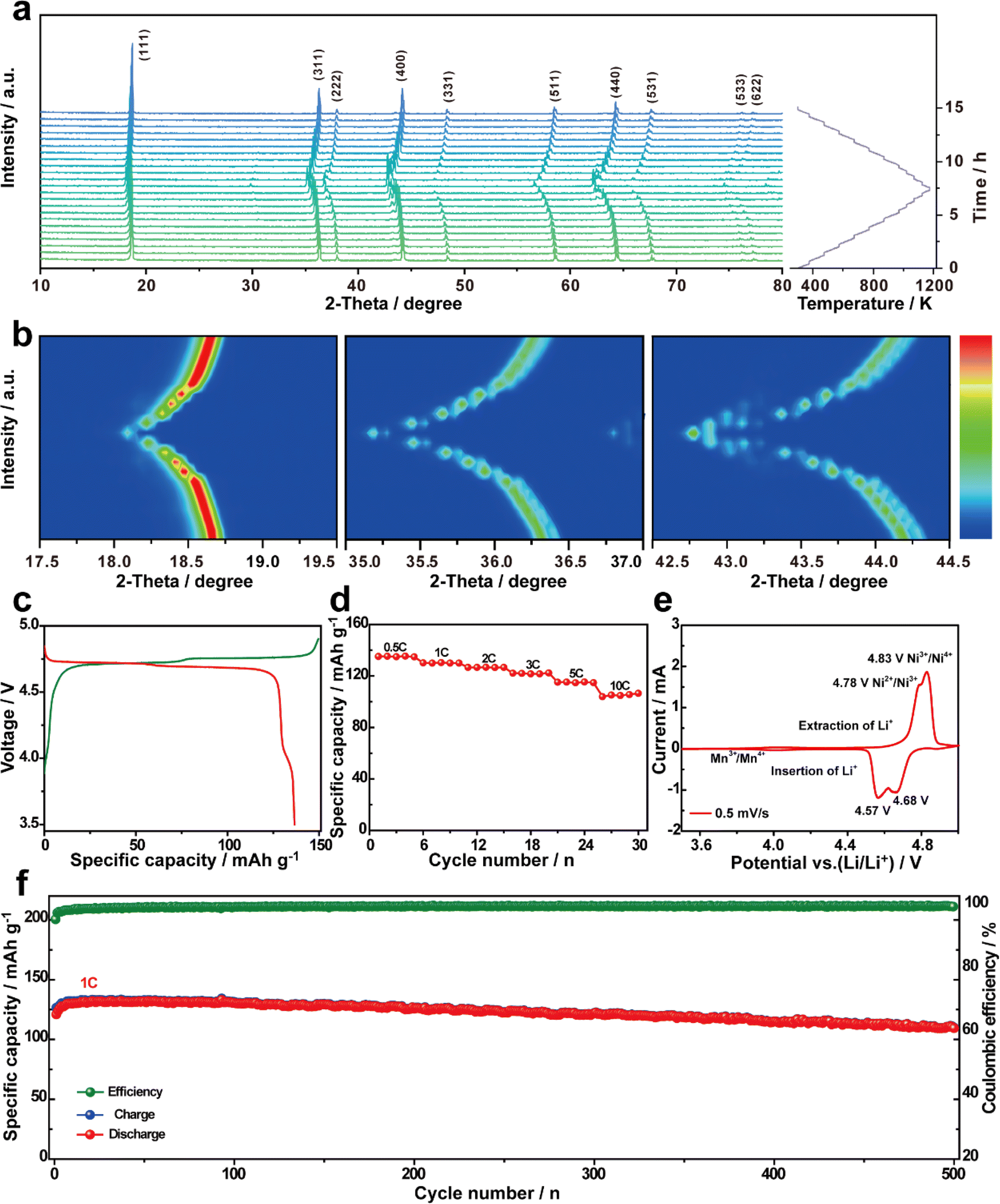 | ||
| Fig. 4 (a) High temperature in situ XRD of LNMO-111. (b) Contour maps of the corresponding area. (c) First galvanostatic charge/discharge curves versus specific capacity at 0.5C. (d) Rate performance at different rates. (e) CV at 0.5 mV s−1. (f) Performance of 500 cycles at a current density of 1C. | ||
The elevated operating voltage of spinel LNMO cathodes in LIBs causes electrolyte decomposition and accelerates side reactions at the electrode/electrolyte interface, which induces poor cycle performance and limits their application.57,58 The manganese elements dissolve in the electrolyte and migrate to the lithium metal anode or remain on the separator driven by concentration gradients or electric field forces. In order to investigate the intrinsic working mechanism of the LNMO-111 cathode, XPS tests were performed on lithium metal and separators after 500 cycles (Fig. S14†). The XPS analyses showed that no manganese elements were detected on the lithium metal and the diaphragm after 500 cycles, which indicates that the dissolved manganese in the LNMO-111 electrode is at a low level. This signifies a critical finding in understanding the behavior of the LNMO-111 cathode during cycling. These findings collectively support the conclusion that the micro–nano hierarchical LNMO porous spherical particles with exposed stable {111} facets effectively exhibit superior structural stability and excellent performance. This observation underscores the stability of the designed material and the implications for its performance.
3. Conclusion
In summary, we have successfully constructed a unique micro–nano hierarchical LNMO-111 porous spherical structure with highly exposed {111} facets for the synthesis of high-performance lithium-ion oxide cathodes through kinetically controlled synthesis. In terms of decomposition kinetics, by controlling the loss of lattice oxygen, the disordered structure can be precisely tuned and the {111} facets are preferentially exposed. The external part of the particles mainly undergoes the lithiation kinetics, and the inside is dominated by the decomposition kinetics, with the internal CO2 being released more quickly, thus resulting in the formation of porous spherical particles with internal cavities. This special micro–nano hierarchical structure displays a smoother surface, and predominant {111} facets with the combined advantages of lowest surface energy and Mn dissolution, a stable cathode–electrolyte interface, and fast Li+ intercalation/deintercalation. Furthermore, its internal voids effectively relieve volumetric strain, enhancing the stability of the structure. As a result, the novel cathode exhibits a remarkable reversible discharge capacity of 136.7 mA h g−1 and corresponding high-energy density of 636.4 W h kg−1 at 0.5C, outstanding cycling stability (90.6% capacity retention after 500 cycles with 1C), and excellent rate capability (78.9% of the initial capacity at 10C). Our study might open up new perspectives for the design of high-performance cathode materials, which could significantly advance the practical application of LIBs.Data availability
Essential data are fully provided in the main text and ESI.†Author contributions
Zhi-Qi Li: writing and original manuscript preparation; Yi-Feng Liu and Han-Xiao Liu: writing and data analysis; Jingqiang Wang, Yan-Fang Zhu, and Lang Qiu: review and editing; Mengke Zhang: characterization testing; Xiao-Dong Guo, Shu-Lei Chou and Yao Xiao: review and supervision. All authors have participated in the design and discussion of the experiments.Conflicts of interest
The authors declare no conflict of interest.Acknowledgements
This work was supported by the National Natural Science Foundation of China (52250710680, 51971124, 52171217, and 52202284), Natural Science Foundation of Zhejiang Province (LZ21E010001 and LQ23E020002), Science and Technology Project of State Grid Corporation of China (5419-202158503A-0-5-ZN), Wenzhou Key Scientific and Technological Innovation Research Project (ZG2023053 and ZG2022032), Wenzhou Natural Science Foundation (G20220019 and G20220021), Cooperation between industry and education project of Ministry of Education (220601318235513), and Wenzhou Science and Technology Association Serves Scientific and Technological Innovation Projects (KJFW0201).References
- X. Lu, Y. Wang, X. Xu, B. Yan, T. Wu and L. Lu, Adv. Energy Mater., 2023, 13, 2301746 CrossRef CAS.
- R. Pandya, L. Valzania, F. Dorchies, F. Xia, J. Mc Hugh, A. Mathieson, H. J. Tan, T. G. Parton, L. Godeffroy, K. Mazloomian, T. S. Miller, F. Kanoufi, M. De Volder, J.-M. Tarascon, S. Gigan, H. B. de Aguiar and A. Grimaud, Nat. Nanotechnol., 2023, 18, 1185–1194 CrossRef CAS PubMed.
- J. Xiao, F. Shi, T. Glossmann, C. Burnett and Z. Liu, Nat. Energy, 2023, 8, 329–339 CrossRef.
- H. Zhang, J. Cheng, H. Liu, D. Li, Z. Zeng, Y. Li, F. Ji, Y. Guo, Y. Wei, S. Zhang, T. Bai, X. Xu, R. Peng, J. Lu and L. Ci, Adv. Energy Mater., 2023, 13, 2300466 CrossRef CAS.
- Z. Zou, H. Xu, H. Zhang, Y. Tang and G. Cui, ACS Appl. Mater. Interfaces, 2020, 12, 21368–21385 CrossRef CAS PubMed.
- X. B. Jia, J. Wang, Y. F. Liu, Y. F. Zhu, J. Y. Li, Y. J. Li, S. L. Chou and Y. Xiao, Adv. Mater., 2024, 36, 2307938 CrossRef CAS PubMed.
- Y. Han, Y. S. Jiang, F. D. Yu, L. Deng, W. Ke, S. J. Zhang, L. F. Que, B. Wu, F. Ding, L. Zhao and Z. B. Wang, Adv. Funct. Mater., 2022, 32, 2207285 CrossRef CAS.
- R. Shimizu, D. Cheng, J. L. Weaver, M. Zhang, B. Lu, T. A. Wynn, R. Burger, M. c. Kim, G. Zhu and Y. S. Meng, Adv. Energy Mater., 2022, 12, 2201119 CrossRef CAS.
- D. Wang, C. Gao, X. Zhou, S. Peng, M. Tang, Y. Wang, L. Huang, W. Yang and X. Gao, Carbon Energy, 2023, 5, e338 CrossRef CAS.
- B. Chang, D. H. Yun, I. Hwang, J. K. Seo, J. Kang, G. Noh, S. Choi and J. W. Choi, Adv. Mater., 2023, 35, 2303787 CrossRef CAS.
- N. M. Jobst, N. Paul, P. Beran, M. Mancini, R. Gilles, M. Wohlfahrt-Mehrens and P. Axmann, J. Am. Chem. Soc., 2023, 145, 4450–4461 CrossRef CAS PubMed.
- G. Liang, V. K. Peterson, Z. Wu, S. Zhang, J. Hao, C. Z. Lu, C. H. Chuang, J. F. Lee, J. Liu, G. Leniec, S. M. Kaczmarek, A. M. D'Angelo, B. Johannessen, L. Thomsen, W. K. Pang and Z. Guo, Adv. Mater., 2021, 33, 2101413 CrossRef CAS.
- X. Zhu, T. U. Schülli, X. Yang, T. Lin, Y. Hu, N. Cheng, H. Fujii, K. Ozawa, B. Cowie, Q. Gu, S. Zhou, Z. Cheng, Y. Du and L. Wang, Nat. Commun., 2022, 13, 1565 CrossRef CAS PubMed.
- T. Wang, B. Chen, C. Liu, T. Li and X. Liu, Angew. Chem., Int. Ed., 2024, 63, e202400960 CrossRef CAS PubMed.
- Y.-C. Li, W. Xiang, Z.-G. Wu, C.-L. Xu, Y.-D. Xu, Y. Xiao, Z.-G. Yang, C.-J. Wu, G.-P. Lv and X.-D. Guo, Electrochim. Acta, 2018, 291, 84–94 CrossRef CAS.
- T. Fu, D. Lu, Z. Yao, Y. Li, C. Luo, T. Yang, S. Liu, Y. Chen, Q. Guo, C. Zheng and W. Sun, J. Mater. Chem. A, 2023, 11, 13889–13915 RSC.
- Z. Yang, W. Xiang, Z. Wu, F. He, J. Zhang, Y. Xiao, B. Zhong and X. Guo, Ceram. Int., 2017, 43, 3866–3872 CrossRef CAS.
- K. Zhang, Z. Xu, G. Li, R. J. Luo, C. Ma, Y. Wang, Y. N. Zhou and Y. Xia, Adv. Energy Mater., 2023, 13, 2302793 CrossRef CAS.
- Z.-C. Jian, Y.-F. Liu, Y.-F. Zhu, J.-Y. Li, H.-Y. Hu, J. Wang, L.-Y. Kong, X.-B. Jia, H.-X. Liu, J.-X. Guo, M.-Y. Li, Y.-S. Xu, J.-F. Mao, S.-L. Zhang, Y. Su, S.-X. Dou, S.-L. Chou and Y. Xiao, Nano Energy, 2024, 125, 109528 CrossRef CAS.
- B. Chen, J. Zhang, D. Wong, T. Wang, T. Li, C. Liu, L. Sun and X. Liu, Angew. Chem., Int. Ed., 2023, 63, e202315856 CrossRef PubMed.
- Y. Su, B. Johannessen, S. Zhang, Z. Chen, Q. Gu, G. Li, H. Yan, J. Y. Li, H. Y. Hu, Y. F. Zhu, S. Xu, H. Liu, S. Dou and Y. Xiao, Adv. Mater., 2023, 35, 2305149 CrossRef CAS PubMed.
- X. L. Li, J. Bao, Y. F. Li, D. Chen, C. Ma, Q. Q. Qiu, X. Y. Yue, Q. C. Wang and Y. N. Zhou, Adv. Sci., 2021, 8, 2004448 CrossRef CAS PubMed.
- J. Zhang, D. Wong, Q. Zhang, N. Zhang, C. Schulz, M. Bartkowiak, K. An, L. Gu, Z. Hu and X. Liu, J. Am. Chem. Soc., 2023, 145, 10208–10219 CrossRef CAS PubMed.
- Y. Shi, J. Yang, J. Yang, Z. Wang, Z. Chen and Y. Xu, Adv. Funct. Mater., 2022, 32, 2111307 CrossRef CAS.
- L. Wang, G. Liu, R. Xu, X. Wang, L. Wang, Z. Yao, C. Zhan and J. Lu, Adv. Energy Mater., 2023, 13, 2203999 CrossRef CAS.
- Y. Zhang, C. Yin, B. Qiu, G. Chen, Y. Shang and Z. Liu, Energy Storage Mater., 2022, 53, 763–773 CrossRef.
- R. Gao, Q. Huang, Z. Zeng, L. Zheng, Y. Zheng, Z. Hu and X. Liu, J. Phys. Chem. Lett., 2019, 10, 6695–6700 CrossRef CAS PubMed.
- X.-Y. Yue, J. Zhang, J. Bao, Y.-F. Bai, X.-L. Li, S.-Y. Yang, Z.-W. Fu, Z.-H. Wang and Y.-N. Zhou, eScience, 2022, 2, 329–338 CrossRef.
- R. Jain, A. S. Lakhnot, K. Bhimani, S. Sharma, V. Mahajani, R. A. Panchal, M. Kamble, F. Han, C. Wang and N. Koratkar, Nat. Rev. Mater., 2022, 7, 736–746 CrossRef CAS.
- L. Lin, L. Zhang, S. Wang, F. Kang and B. Li, J. Mater. Chem. A, 2023, 11, 7867–7897 RSC.
- S. Zhang, K. Wang, Z. Hou, C. Sun, Y. Hou, D. Zhang and F. Li, ACS Appl. Nano Mater., 2022, 5, 12826–12835 CrossRef CAS.
- W. Dong, X.-X. Zeng, X.-D. Zhang, J.-Y. Li, J.-L. Shi, Y. Xiao, Y. Shi, R. Wen, Y.-X. Yin, T.-s. Wang, C.-R. Wang and Y.-G. Guo, ACS Appl. Mater. Interfaces, 2018, 10, 18005–18011 CrossRef CAS PubMed.
- Y. Li, J. Qin, Y. Ding, J. Ma, P. Das, H. Liu, Z.-S. Wu and X. Bao, ACS Catal., 2022, 12, 12765–12773 CrossRef CAS.
- L. Zhang, C. Guan, Y. Xie, H. Li, A. Wang, S. Chang, J. Zheng, Y. Lai and Z. Zhang, ACS Appl. Mater. Interfaces, 2022, 14, 18313–18323 CrossRef CAS PubMed.
- L.-Y. Kong, H.-X. Liu, Y.-F. Zhu, J.-Y. Li, Y. Su, H.-W. Li, H.-Y. Hu, Y.-F. Liu, M.-J. Yang, Z.-C. Jian, X.-B. Jia, S.-L. Chou and Y. Xiao, Sci. China: Chem., 2023, 67, 191–213 CrossRef.
- J. Bao, H.-J. Pei, X.-Y. Yue, X.-L. Li, C. Ma, R.-J. Luo, C.-Y. Du and Y.-N. Zhou, Nano Res., 2022, 16, 8345–8353 CrossRef.
- C. Ke, R. Shao, Y. Zhang, Z. Sun, S. Qi, H. Zhang, M. Li, Z. Chen, Y. Wang, B. Sa, H. Lin, H. Liu, M. S. Wang, S. Chen and Q. Zhang, Adv. Funct. Mater., 2022, 32, 2205635 CrossRef CAS.
- G. Li, S. Guo, B. Xiang, S. Mei, Y. Zheng, X. Zhang, B. Gao, P. K. Chu and K. Huo, Energy Mater., 2022, 2, 200020 CrossRef CAS.
- M.-J. Xiao, B. Ma, H. Zhang, X.-Y. Li, Q. Wang, Y. Peng and H.-L. Zhang, J. Mater. Chem. A, 2022, 10, 21492–21502 RSC.
- Z.-Y. Yu, Q. Sun, H. Li, Z.-J. Qiao, W.-J. Li, S.-L. Chou, Z.-J. Zhang and Y. Jiang, Rare Met., 2023, 42, 2982–2992 CrossRef CAS.
- Y. Xiao, Y. Zhu, T. Gao, B. Zhong and X. Guo, Ionics, 2016, 23, 27–34 CrossRef.
- J. Cen, B. Zhu, S. R. Kavanagh, A. G. Squires and D. O. Scanlon, J. Mater. Chem. A, 2023, 11, 13353–13370 RSC.
- J. Y. Li, H. Y. Hu, L. F. Zhou, H. W. Li, Y. J. Lei, W. H. Lai, Y. M. Fan, Y. F. Zhu, G. Peleckis, S. Q. Chen, W. K. Pang, J. Peng, J. Z. Wang, S. X. Dou, S. L. Chou and Y. Xiao, Adv. Funct. Mater., 2023, 33, 2213215 CrossRef CAS.
- B. P. Shivamurthy, M. Thripuranthaka, M. V. Shelke and G. P. Nayaka, ACS Appl. Energy Mater., 2022, 5, 15345–15355 CrossRef CAS.
- J. Liu, G. Li, Y. Yu, H. Bai, M. Shao, J. Guo, C. Su, X. Liu and W. Bai, J. Alloys Compd., 2017, 728, 1315–1328 CrossRef CAS.
- Z. Fang, X.-L. Zhang, X.-Y. Hou, W.-L. Huang and L.-B. Li, Rare Met., 2022, 41, 2268–2279 CrossRef CAS.
- S. L. Spence, A. Hu, M. Jiang, Z. Xu, Z. Yang, M. M. Rahman, L. Li, Y. S. Chu, X. Xiao, X. Huang and F. Lin, ACS Energy Lett., 2022, 7, 690–695 CrossRef CAS.
- M. Fehse, N. Etxebarria, L. Otaegui, M. Cabello, S. Martín-Fuentes, M. A. Cabañero, I. Monterrubio, C. F. Elkjær, O. Fabelo, N. A. Enkubari, J. M. López del Amo, M. Casas-Cabanas and M. Reynaud, Chem. Mater., 2022, 34, 6529–6540 CrossRef CAS PubMed.
- J. Zhu, W. Xu, M. Knapp, M. S. Dewi Darma, L. Mereacre, P. Su, W. Hua, X. Liu-Théato, H. Dai, X. Wei and H. Ehrenberg, Cell Rep. Phys. Sci., 2023, 4, 101464 CrossRef CAS.
- S. Li, Z. Liu, L. Yang, X. Shen, Q. Liu, Z. Hu, Q. Kong, J. Ma, J. Li, H.-J. Lin, C.-T. Chen, X. Wang, R. Yu, Z. Wang and L. Chen, Nano Energy, 2022, 98, 107335 CrossRef CAS.
- J. He, G. Melinte, M. S. D. Darma, W. Hua, C. Das, A. Schökel, M. Etter, A. L. Hansen, L. Mereacre, U. Geckle, T. Bergfeldt, Z. Sun, M. Knapp, H. Ehrenberg and J. Maibach, Adv. Funct. Mater., 2022, 32, 2207937 CrossRef CAS.
- W. Yang, L. Chang, S. Luo, X. Bi, S. Cao, A. Wei, J. Liu and F. Zhang, Int. J. Energy Res., 2022, 46, 18495–18510 CrossRef CAS.
- L. Wang, H. Li, X. Huang and E. Baudrin, Solid State Ionics, 2011, 193, 32–38 CrossRef CAS.
- Y. Wang, Y. Lv, Y. Su, L. Chen, H. Li and F. Wu, Nano Energy, 2021, 90, 106589 CrossRef CAS.
- Y. Xiao, Y. F. Zhu, H. R. Yao, P. F. Wang, X. D. Zhang, H. Li, X. Yang, L. Gu, Y. C. Li, T. Wang, Y. X. Yin, X. D. Guo, B. H. Zhong and Y. G. Guo, Adv. Energy Mater., 2019, 9, 1803978 CrossRef.
- J. Wang, Y.-F. Zhu, Y. Su, J.-X. Guo, S. Chen, H.-K. Liu, S.-X. Dou, S.-L. Chou and Y. Xiao, Chem. Soc. Rev., 2024, 53, 4230–4301 RSC.
- F. Zou, H. C. Nallan, A. Dolocan, Q. Xie, J. Li, B. M. Coffey, J. G. Ekerdt and A. Manthiram, Energy Storage Mater., 2021, 43, 499–508 CrossRef.
- J. Guo, Y. Li, Y. Chen, S. Deng, J. Zhu, S. Wang, J. Zhang, S. Chang, D. Zhang and X. Xi, J. Alloys Compd., 2019, 811, 152031 CrossRef CAS.
Footnote |
| † Electronic supplementary information (ESI) available. See DOI: https://doi.org/10.1039/d4sc02754j |
| This journal is © The Royal Society of Chemistry 2024 |