
 Open Access Article
 This Open Access Article is licensed under a Creative Commons Attribution-Non Commercial 3.0 Unported Licence
3D vs. turbostratic: controlling metal–organic framework dimensionality via N-heterocyclic carbene chemistry†
Ilia
Kochetygov
 a,
Anita
Justin
a,
Mehrdad
Asgari
ab,
Shuliang
Yang
ac,
Vikram
Karve
a,
Till
Schertenleib
a,
Dragos
Stoian
d,
Emad
Oveisi
e,
Mounir
Mensi
a and
Wendy L.
Queen
*a
a,
Anita
Justin
a,
Mehrdad
Asgari
ab,
Shuliang
Yang
ac,
Vikram
Karve
a,
Till
Schertenleib
a,
Dragos
Stoian
d,
Emad
Oveisi
e,
Mounir
Mensi
a and
Wendy L.
Queen
*a
aInstitute of Chemical Sciences and Engineering, École Polytechnique Fédérale de Lausanne (EPFL), CH-1951 Sion, Switzerland. E-mail: wendy.queen@epfl.ch
bDepartment of Chemical Engineering & Biotechnology, University of Cambridge, Philippa Fawcett Drive, Cambridge CB3 0AS, UK
cCollege of Energy, Xiamen University, Xiamen, Fujian 361102, China
dSwiss–Norwegian Beamlines, ESRF, BP 220, Grenoble, 38043, France
eInterdisciplinary Centre for Electron Microscopy (CIME), École Polytechnique Fédérale de Lausanne (EPFL), CH-1015 Lausanne, Switzerland
First published on 11th May 2022
Abstract
Using azolium-based ligands for the construction of metal–organic frameworks (MOFs) is a viable strategy to immobilize catalytically active N-heterocyclic carbenes (NHC) or NHC-derived species inside MOF pores. Thus, in the present work, a novel copper MOF referred to as Cu-Sp5-BF4, is constructed using an imidazolinium ligand, H2Sp5-BF4, 1,3-bis(4-carboxyphenyl)-4,5-dihydro-1H-imidazole-3-ium tetrafluoroborate. The resulting framework, which offers large pore apertures, enables the post-synthetic modification of the C2 carbon on the ligand backbone with methoxide units. A combination of X-ray diffraction (XRD), solid-state nuclear magnetic resonance (ssNMR) and electron microscopy (EM), are used to show that the post-synthetic methoxide modification alters the dimensionality of the material, forming a turbostratic phase, an event that further improves the accessibility of the NHC sites promoting a second modification step that is carried out via grafting iridium to the NHC. A combination of X-ray absorption spectroscopy (XAS) and X-ray photoelectron spectroscopy (XPS) methods are used to shed light on the iridium speciation, and the catalytic activity of the Ir–NHC containing MOF is demonstrated using a model reaction, stilbene hydrogenation.
1. Introduction
Metal–organic frameworks (MOFs), a class of porous materials that consist of metal ions or metal ion clusters interlinked by organic ligands,1 offer promise in many applications in host-guest chemistry such as catalysis,2 gas separation, drug delivery, etc.3–5 These frameworks are particularly attractive because they offer record internal surface areas and pore volumes, combined with a wide range of structural and chemical tunability that stems from their highly modular nature.6–8 In fact, through the judicious selection and/or modification of MOF building blocks, one can gain access to a plethora of porous structures that are tailored for the desired application. As an example, constructing MOFs from heterocyclic imidazolinium-based ligands, which can be post-synthetically treated to form N-heterocyclic carbenes (NHCs) or NHC-derived species, is an interesting topic to explore. The design of such materials could endow MOFs with a range of tunable reactivity for a variety of interesting catalytic applications such as Suzuki–Miyaura C–C coupling,9 CO2 conversion10–12 and hydrogenation.13 Moreover, the highly crystalline nature of MOFs, combined with the high tunability of the catalytically active NHC sites, could enable structure–property correlation studies, providing mechanistic insight into various NHC-based catalytic reactions in the future.Within the literature, a few MOFs have been constructed from unsaturated imidazolium-based ligands for the subsequent formation of NHCs or NHC-based complexes inside the MOF pores;14,15 however, to date, the use of saturated imidazolinium building blocks for MOF construction remains elusive. When compared to their unsaturated counterparts, saturated imidazolinium building blocks are becoming increasingly attractive as they can offer a higher degree of structural tunability (with the possible formation of 5, 6, and 7-membered rings),16 and the resulting NHCs are generally stronger σ-donors,17 therefore, forming stronger bonds and more stable complexes with transition metals.18 These attributes stem from the lack of conjugation in the saturated N-heterocyclic ring and the stronger donating power of the –CH2 groups.19 In addition to this, the syntheses of previously reported saturated imidazolinium salts (without carboxyl groups) are generally facile.20–22 Moreover, their corresponding C2 atoms undergo deprotonation in mildly basic media readily forming NHCs and NHC-metal complexes.23 Given this, we recently designed a new ligand, H2Sp5-BF4 that bears a saturated 5-membered N-heterocyclic ring and two carboxylate groups, making it useful for MOF construction. From this ligand, a microporous MOF, Cu-Sp5, was subsequently synthesized.24,25 While the material exhibits an interesting combination of open metal sites and charged ion pairs, two structural features that lead to a remarkable CO2/N2 selectivity for potential gas separations, the framework also featured interpenetration. This structural feature leads to a small pore size, which is not optimal to access the reactive C2 site on the imidazole ligand, as it is thought to impede the formation of an NHC or NHC-derived metal complex inside the MOF pore space. Thus, to overcome this, we have continued to synthesize other MOFs using the H2Sp5-BF4 ligand. To our delight, the new MOF presented here, Cu-Sp5-BF4, features a non-interpenetrated structure that possesses larger, nanometer-sized pores that are an important prerequisite for post-synthetic NHC chemistry. Indeed, the NHCs can be readily accessed in the new MOF, and this is demonstrated through the post-synthetic formation of NHC-methoxide adducts. Moreover, it is found that methoxide modification leads to a change in the material's dimensionality with the formation of a disordered turbostratic phase. It is observed that after further treatment of the MOF with [Ir(cod)(OMe)]2 (cod stands for 1,5-cyclooctadiene, OMe stands for methoxide), NHC-iridium complexes are also readily formed inside the MOF pore for catalytic applications. To the best of our knowledge, only one previous work showed the incorporation of an NHC–iridium complex inside a MOF, using a pre-formed metallolinker.26 Moreover, it is shown for the first time that the turbostratic structure significantly improves the iridium loading inside the MOF when compared to the non-turbostratic analog. It is concluded that the post-synthetic formation of Ir–NHC complexes inside the MOF is strongly dependent on the presence of defects induced by the methoxide modification. Last, a combination of XAS and XPS techniques is further used to shed light on the iridium speciation inside the MOF structure and the catalytic activity of the Ir-functionalized MOF is demonstrated using a model reaction, stilbene hydrogenation.
2. Results and discussion
2.1. Material synthesis
Having shown the applicability of a new ligand H2Sp5-BF4 for MOF construction in previous work,24 we have continued exploratory efforts to synthesize new MOFs from this ligand. The previously reported MOF, Cu-Sp5, was synthesized using copper(II) nitrate and features an interpenetrated structure with nitrate ions found inside the material's pore. As this material is interpenetrated, its pore size is small and this is believed to inhibit access to the C2 carbon on the ligand backbone and hence prevent NHC chemistry inside the MOF pore. It was hypothesized that using a copper salt featuring a bulkier anion might help prevent structural interpenetration. Thus, in subsequent syntheses, a copper(II) tetrafluoroborate salt was used as the copper source instead of copper(II) nitrate, while keeping the other synthetic conditions (temperature, solvent, concentration) similar. Using single-crystal X-ray diffraction (SCXRD), a new MOF structure, Cu-Sp5-BF4-EtOH, that is different from the previously reported Cu-Sp5, was found (Fig. S1†). Given the similarities in the material's synthetic conditions, the structural differences in these two frameworks are attributed to the increased steric bulk of tetrahedral BF4− anion when compared to the flat, triangular nitrate anion found in the previously reported Cu-Sp5 structure. Interestingly, the coordination environment of Cu(II) found in the secondary building unit (SBU) of Cu-Sp5-BF4-EtOH consists of infinite 1D chains as depicted in Fig. 1, while Cu-Sp5 consists of discrete Cu-paddlewheel SBUs (Fig. S1†).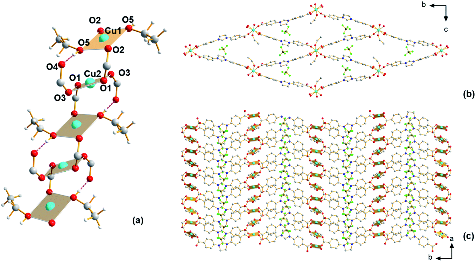 | ||
| Fig. 1 Structure of Cu-Sp5-BF4-EtOH. (a) View of SBU, (b) view along the a axis depicting channel front, and (c) view along the c axis depicting walls of the channel and connection of SBUs with linkers. Hydrogen atoms on (b) and (c) are omitted for clarity. The hydrogen bond between O4 and O5 is highlighted in purple. Atom colors: C, gray; O, red; N, blue; H, white; B, brown; F, green; Cu, turquoise. | ||
For the Cu-Sp5-BF4-EtOH structure, there are two crystallographically distinct copper sites present, and both metal ions, labeled Cu1 and Cu2, have a square planar geometry. Cu1 is connected to two bridging carboxylates that are in a trans orientation relative to each other (Cu1–O2 = 1.931(2) Å) and two ethanol molecules (Cu1–O5 = 1.929(2) Å); Cu2 is connected to four carboxylates, two of which are bridging the Cu1 and Cu2 ions (Cu2–O1 = 1.929(2) Å) and two that are dangling in the MOF pore space (Cu2–O3 1.970(2) Å). The dangling O4 atoms on the carboxylate units are also hydrogen-bonded to the ethanol molecules coordinated to the Cu1 atom (O4–O5 = 2.524(4) Å). The Cu1–Cu2 distance is 3.3196(3) Å, and the carboxylate bridges found between the two Cu(II) ions lead to the formation of a 1D, rod-like SBU that propagates infinitely along the crystallographic a axis (Fig. 1a). In addition, the carboxylates interconnect SBUs in a rhombic fashion within the bc plane forming a 3D channeled structure (Fig. 1b and c). The BF4− anions are positioned inside these channels next to the charged imidazolinium rings (see Table S1† for refinement details). The phase purity of the material is confirmed by a full agreement between the experimental and calculated PXRD pattern of Cu-Sp5-BF4-EtOH (Fig. S2†).
Using single-crystal X-ray diffraction, ethanol molecules are seen bound to the copper atoms; thus, prior to performing any further studies, efforts were made to liberate the ethanol that occupies part of the pore space to possibly provide access to coordinatively unsaturated open Cu(II) sites. For this, TGA experiments were first carried out, which reveal (Fig. S3†) a broad weight loss between 90 and 200 °C that is attributed to the removal of ethanol from the pores of the material. Thus, the selected activation protocol entails heating the material to 185 °C under vacuum for 16 hours. During this time, a color change was observed from pale blue to dark green. Interestingly, the powder pattern of the activated structure, denoted Cu-Sp5-BF4-A, does not match the PXRD pattern obtained from the solvated parent material (Fig. S4†); although, high crystallinity of the sample is retained during activation as indicated by well-defined diffraction peaks at high 2θ angles. Further, after activation, the Cu-Sp5-BF4-A material did not revert to the structure of the parent material upon soaking in ethanol, even after a 36 hour soak time (Fig. S4†), indicating an irreversible structural transition and prompting a further examination of the material's structure. SCXRD performed on activated single crystals (See Table S1† for refinement details) revealed a drastic change in the copper-containing SBU from the aforementioned 1D rod-like SBU to a stack of copper paddlewheels (Fig. 2a). There are three independent copper sites in the structure. Inside the paddlewheels, the Cu2–Cu3 distance is 2.594(2) Å and Cu1–Cu1 distance is 2.585(2) Å, while between the paddlewheels the Cu1–Cu3 distance is 3.184(3) Å and Cu2–Cu2 distance is 3.203(2) Å. On the contrary, the shortest Cu–Cu distance observed in the solvated parent structure, Cu-Sp5-BF4-EtOH, is 3.3196(3) Å. This rearrangement of the Cu(II) ions is driven by the decoordination of ethanol molecules that yields vacant copper coordination sites that then become occupied by the carboxylates that were found dangling in the pore of the parent material. This change in the coordination of the carboxylates thus leads to the formation of Cu paddlewheel units, causing ligand buckling (Fig. 2b) and a significant contraction of the SBU along the a axis (Fig. 2c). Such a process further leads to contraction of the longer pore window dimension from 33.5424(9) Å in Cu-Sp5-BF4-EtOH to 31.562(5) Å for Cu-Sp5-BF4, and an increase in the shorter pore dimension from 11.4021(9) Å to 14.861(3) Å, respectively (Fig.Fig. S7 S5†). The activation process was also followed via synchrotron PXRD experiments; data were collected from 27 °C to 190 °C while the sample was kept under a dynamic vacuum (<10−2 mbar). The experiment reveals the first signs of new phase formation at 140–145 °C, in line with the weight loss observed in the TGA data and hence, corresponds to ethanol de-coordination and removal from the structure (Fig. S6†). Moreover, the phase purity and the high degree of crystallinity of the newly formed material, Cu-Sp5-BF4-A, are proven by a full agreement between the experimental and simulated powder patterns (Fig. S7†).
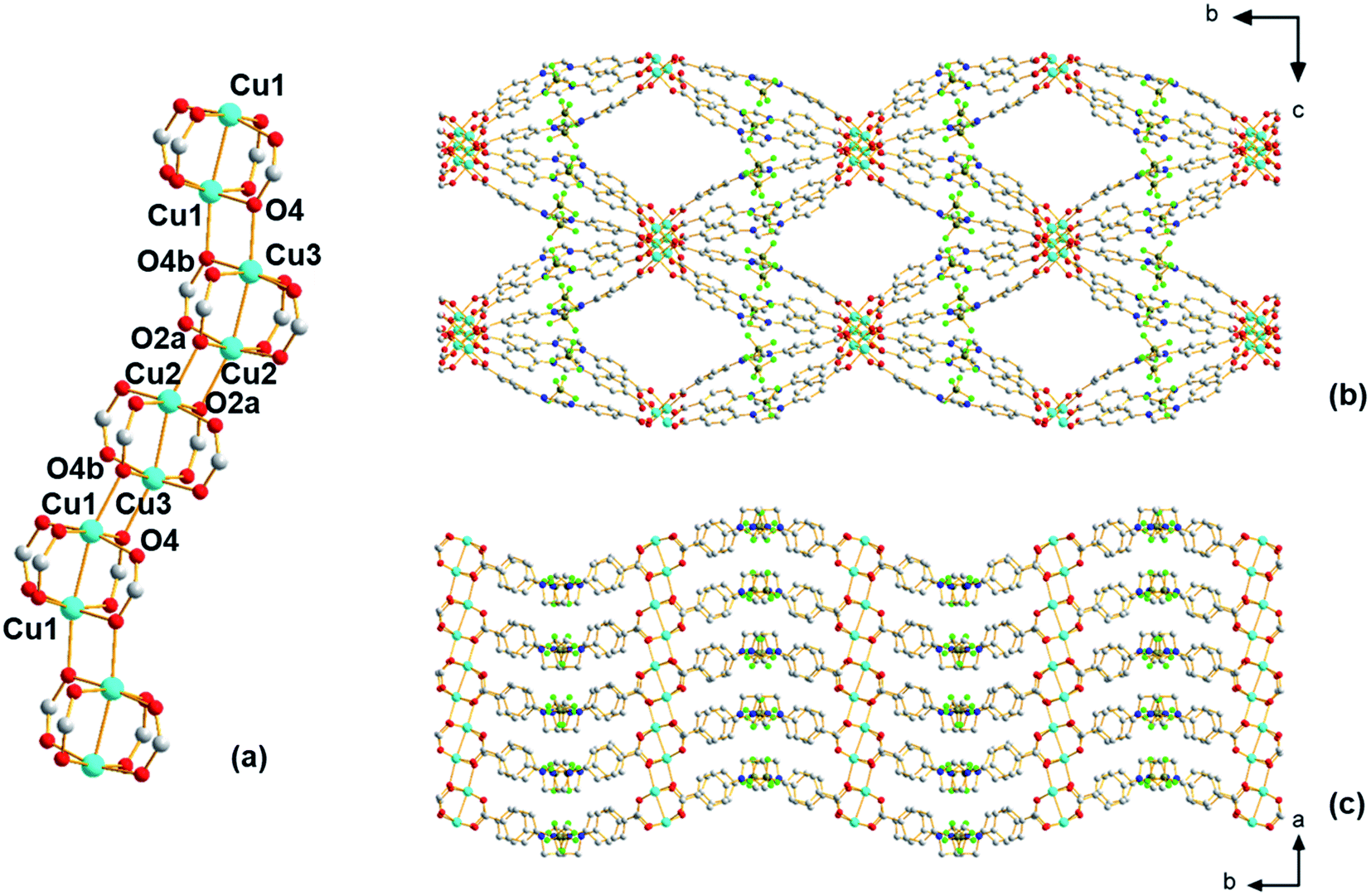 | ||
| Fig. 2 Structure of Cu-Sp5-BF4-A. (a) View of SBU, (b) view along the a axis depicting channel front, and (c) view along the c axis depicting walls of the channel and paddlewheel SBUs. Hydrogen atoms are omitted for clarity. Atom colors: C, gray; O, red; N, blue; H, white; B, brown; F, green; Cu, turquoise. | ||
Despite the presence of Cu paddlewheels in the new Cu-Sp5-BF4-A structure, it is noted that there are no open metal coordination sites. The reason is that the apical Cu(II) sites are instead occupied by the oxygen atoms of adjacent paddlewheel units, with the following distances: Cu2–O2a 2.19(1) Å, Cu1–O4b 2.20(1) Å, and Cu3–O4 2.25(1) Å. This inaccessibility of the copper is unusual when compared to the previously reported MOF structures containing Cu-paddlewheels, such as Cu-Sp5, HKUST-1 and Cu-TDPAT.27 To the best of our knowledge, a similar paddlewheel arrangement was reported only once before for STAM-17-OEt, a material that features a trigonal/hexagonal kagome-type net composed of copper paddlewheels interlinked with 5-ethoxy isophthalate.28 For Cu-Sp5-BF4-A, the inaccessibility of Cu was further verified by in situ FTIR experiments using CO gas as a probe for the Lewis acidic Cu(II). If there were open Cu sites, their interaction with CO would be observed leading to a change in a CO vibration frequency compared to the free CO gas. In the experiments conducted with Cu-Sp5-BF4-A, minimal signal attributed to CO bound to an open Cu(II) site was detected upon dosing the gas up to 20 Torr at 150 K (Fig. S8a†). When compared to the spectrum of Cu-Sp5, assessed under similar conditions (Fig. S8b†), one can see that the relative intensity of Cu-bound CO at 2135 cm−1 is much less for Cu-Sp5-BF4-A than Cu-Sp5. Moreover, there is also a strong signal present for free CO (average peak position at 2143 cm−1) in Cu-Sp5-BF4-A (Fig. S8a†). These results indicate that most of the Cu(II) is coordinatively saturated in Cu-Sp5-BF4-A, a finding that is in contrast to Cu-Sp5, where there is a negligible signal from free CO at all pressures studied. We attribute the weak signal of Cu(II) bound CO in Cu-Sp5-BF4-A to the terminal paddlewheels present at the external crystal surface or on defect sites, which could arise from layer misalignment in the crystal structure.
Having elucidated the structure of the activated material, efforts were made to investigate the porosity of Cu-Sp5-BF4-A. For this, nitrogen adsorption measurements were first carried out at 77 K post-activation (Fig. S9,† bottom); however, there was low N2 adsorption and hence limited surface area (131 m2 g−1 BET, 159 m2 g−1 Langmuir) was detected. This is not surprising as previous studies have shown limited N2 adsorption at both 77 K and room temperature when frameworks are constructed by charge-bearing moieties like imidazolinium ligands.24,29–32 Thus, adsorption measurements were also carried out at 195 K, instead using CO2 as a probe (Fig. S9,† top). Indeed, due to the lack of framework interpenetration, the Cu-Sp5-BF4-A material has more than twice the surface area (544 m2 g−1, Langmuir) and total gas uptake (6.20 mmol g−1 at p/p0 = 0.90) when compared to the Cu-Sp5 (204 m2 g−1, Langmuir, 2.38 mmol g−1 at p/p0 = 0.95) structure, which has the same chemical composition except for a different anion. Cu-Sp5-BF4-A also has a lower isosteric heat of CO2 adsorption (-Qst), 36.6 kJ mol−1 at zero coverage, compared to 43.1 kJ mol−1 for Cu-Sp5 (Fig. S10†). This is attributed to the absence of a large number of accessible open metal coordination sites in Cu-Sp5-BF4-A. Moreover, the smaller pore size of Cu-Sp5 could provide multiple CO2 interactions with the internal MOF wall thus boosting the binding energy. This, combined with a higher charge density in the smaller pore, likely make the Cu-Sp5 pore more energetically favorable towards CO2 when compared to the larger pore of Cu-Sp5-BF4-A with lower charge density. Albeit small, it is noted that the N2 uptake at 77 K for Cu-Sp5-BF4-A is 1.70 mmol g−1 at p/p0 = 0.918 (Fig. S9†), while Cu-Sp5 has negligible N2 uptake at this pressure;24 this difference also likely stems from the larger pore space of Cu-Sp5-BF4-A, which leads to lower charge density and hence less N2 repulsion coupled with easier accessibility to the larger N2 molecule.
2.2. Methoxide treatment
The larger pore size and surface area of the new material, Cu-Sp5-BF4-A, implied that the carbene sites in the pore might be accessible for post-synthetic modification. Thus, a reaction with sodium methoxide (1.05 equiv.) in anhydrous methanol was carried out to test this hypothesis, leading to the formation of NHC-methoxide adducts as shown in Scheme 1. Thus, efforts were made to monitor the alkoxide modification by quantifying the amount of BF4− ions retained in the structure via ICP of the digested samples. Indeed, as the Cu![[thin space (1/6-em)]](https://www.rsc.org/images/entities/char_2009.gif) :ligand ratio in the material is 1:1, a detectable decrease in the amount of boron relative to copper will indicate the extent of the modification as the ligand goes from charged to neutral, releasing BF4− ions into the reaction solution. In fact, upon treatment of the MOF with sodium methoxide in methanol, the B:Cu ratio decreased from approximately 1.02(3):1 in the untreated Cu-Sp5-BF4-A to 0.22(2):1 in the newly formed material. This corresponds to the retention of only 22(2)% of the BF4− in the structure and implies the successful formation of NHC-methoxide adducts. The new material is denoted as Cu-Sp5-OMe. The formation of NHC-methoxide adducts is further supported by solid-state 13C NMR; alongside the peaks associated with unmodified ligands, new, peaks are observed for the methoxide adduct (Fig. S11†). The relative peak positions are consistent with those of methoxide adducts previously observed in solution-based NHC chemistry.33 Moreover, the broad width of the new peaks likely indicates a crystallographic disorder of the methoxide units, a phenomenon inciting further investigation via powder X-ray diffraction. On the contrary, the residual sharp peaks in the 13C NMR spectrum that correspond to the unmodified ligand indicate that a certain part of the material contains the pristine, charged ligands, which are more ordered relative to the methoxide modified ones.
:ligand ratio in the material is 1:1, a detectable decrease in the amount of boron relative to copper will indicate the extent of the modification as the ligand goes from charged to neutral, releasing BF4− ions into the reaction solution. In fact, upon treatment of the MOF with sodium methoxide in methanol, the B:Cu ratio decreased from approximately 1.02(3):1 in the untreated Cu-Sp5-BF4-A to 0.22(2):1 in the newly formed material. This corresponds to the retention of only 22(2)% of the BF4− in the structure and implies the successful formation of NHC-methoxide adducts. The new material is denoted as Cu-Sp5-OMe. The formation of NHC-methoxide adducts is further supported by solid-state 13C NMR; alongside the peaks associated with unmodified ligands, new, peaks are observed for the methoxide adduct (Fig. S11†). The relative peak positions are consistent with those of methoxide adducts previously observed in solution-based NHC chemistry.33 Moreover, the broad width of the new peaks likely indicates a crystallographic disorder of the methoxide units, a phenomenon inciting further investigation via powder X-ray diffraction. On the contrary, the residual sharp peaks in the 13C NMR spectrum that correspond to the unmodified ligand indicate that a certain part of the material contains the pristine, charged ligands, which are more ordered relative to the methoxide modified ones.
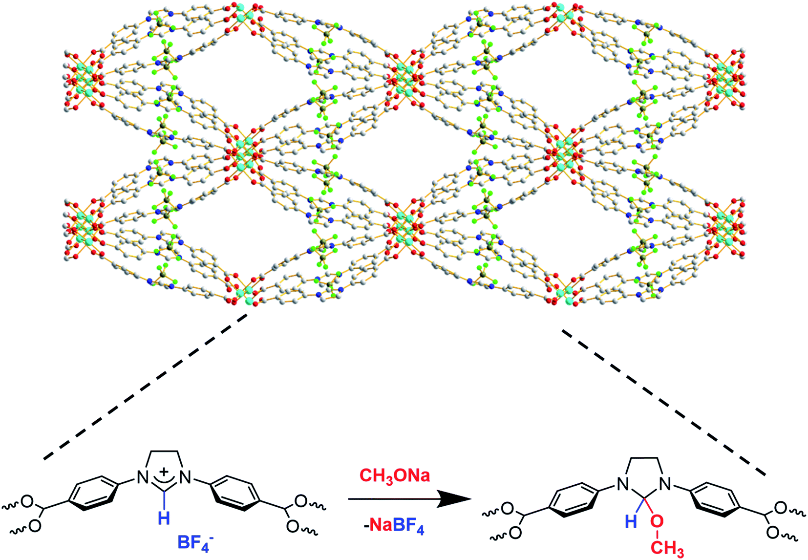 | ||
| Scheme 1 Schematic of NHC-methoxide modification inside Cu-Sp5-BF4-A. | ||
The powder diffraction pattern of this material showed loss of order along the a axis, which was the stacking direction of the Cu-paddlewheels in the original crystal structure. This was determined based on the disappearance of the major hkl peaks where h ≠ 0 (Fig. S12†). On the contrary, peaks representing 0 kl diffraction planes were retained. This change could be due to a decrease in the electrostatic interactions between the layers owed to a decrease in the amount of BF4− ions and disruption of the apical Cu–O bonds, both of which would additionally help hold the layers together. Moreover, an increased weight loss in the TGA of the vacuum-dried Cu-Sp5-OMe (4.3 wt%) compared to Cu-Sp5-BF4-A (3.1 wt%) below 150 °C (Fig. S13†) indicates the presence of extra solvent which could be coordinated to newly formed open metal sites. The latter could originate from the insertion of solvent and detachment of the apical oxygen atoms that were bridging between neighboring Cu-paddlewheels in Cu-Sp5-BF4-A (see Fig. 2a). On the contrary, the presence of additional solvent is not easily observed after MOF digestion and subsequent NMR analysis due to a partial ligand hydrolysis and the large peak breadth caused by the infleunce of paramagnetic Cu2+ (Fig. S14†). However, the peak at 3.36 ppm could be attributed to either water or MeOH, at least confirming the presence of solvent in the material pore. Further, light microscope images indicate that this modification results in a bending of the methoxide modified MOF particles (Fig. S15†), and subsequent SEM images indicate the formation of a large number of defects such as bending and cracking of the MOF crystals, both of which are likely attributed to misalignment between the MOF layers (Fig. 3) as their interlayer interactions weaken. These observations are typical for turbostratic materials, such as graphite.34–37 Moreover, the cracks are transversely oriented with respect to the MOF pore and the crystallographic a axis, as indicated by indexing carried out during SCXRD measurements (Fig. S16†). Together with the loss of order along the a axis, as indicated by PXRD, this supports the idea that the driving force for the formation of such defects is related to weakened interaction between layers, which gives rise to the turbostratic Cu-Sp5-OMe. It is noted that the Langmuir surface area of this material, 432 m2 g−1, is slightly lower than that of Cu-Sp5-A, 544 m2 g−1, as determined by CO2 adsorption measurements carried out at 195 K (Fig. S17†); this phenomenon is likely owed to the layer misalignment and/or the decrease in the quantity of charged species inside the MOF pore (due to the loss of BF4−). On the contrary, the BET surface area of Cu-Sp5-OMe determined by N2 adsorption at 77 K is 175 m2 g−1; this value, which is higher than Cu-Sp5-BF4-A, 131 m2 g−1 (Fig. S18†), likely again stems from the decreased charge in the MOF pore making it more favorable to N2. The significantly lower surface determined from N2 adsorption in Cu-Sp5-OMe, when compared to CO2, corroborates the idea that there is a partial retention of the charged BF4− species in the pores.
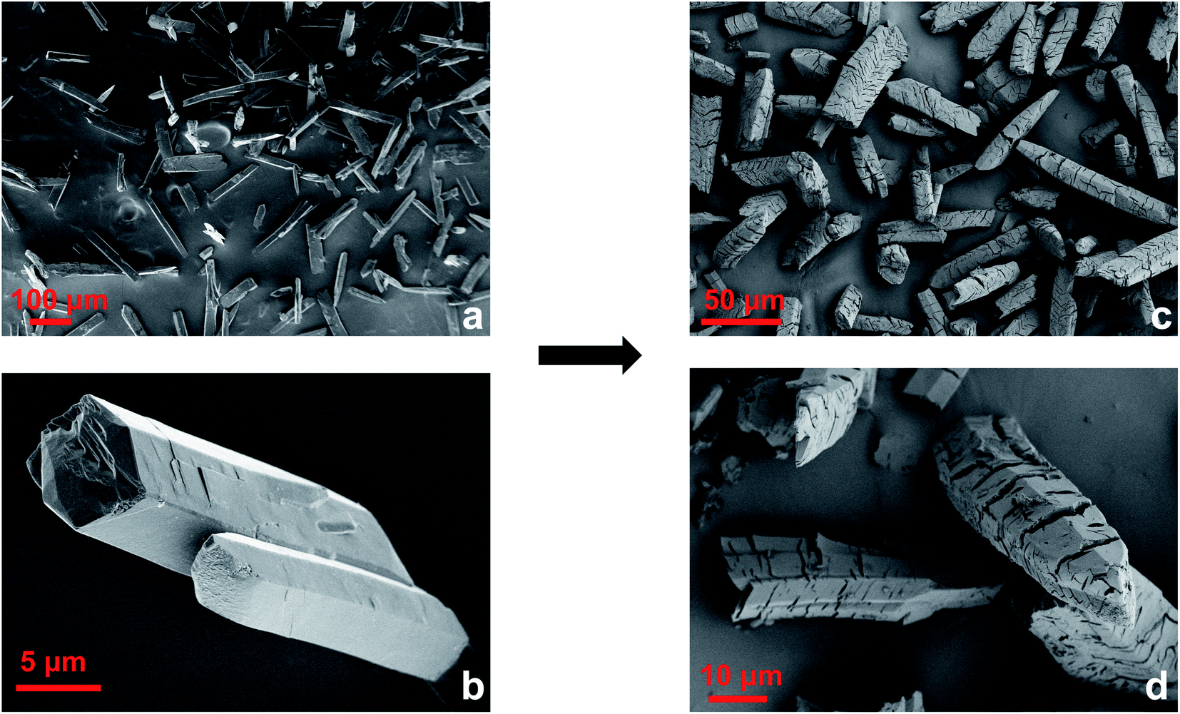 | ||
| Fig. 3 SEM images of Cu-Sp5-BF4-A (a and b) and Cu-Sp5-OMe (c and d). | ||
To better understand the defect formation mechanism, several control experiments were conducted. Firstly, Cu-Sp5-BF4-A was treated with pure anhydrous methanol in absence of sodium methoxide to investigate what role the solvent plays in the transformation process. Interestingly, unlike the EtOH treatment, which did not influence the structure of the material (Fig. S4†), the MeOH treatment resulted in a phase transformation and a chage in the crystal morphology. Based on notable peak shifts in the PXRD (Fig. S19†) pattern, the SEM images (Fig. S20a and b†), and the observed color change from green to blue upon drying (Fig. S20c and d†), we suspect that the methanol coordinates to the paddlewheel sites, interrupting the inter-paddlewheel bonds and leading to a separation of layers. As the small crystal size prevented the structure determination of this material, a detailed structural analysis constitutes an area for future investigations.
Next, a treatment of Cu-Sp5-BF4-A with 1.5 equiv. of sodium methoxide in anhydrous methanol was conducted to investigate the effect that larger amounts of sodium methoxide might have on the formation of Cu-Sp5-OMe. Notably, it was found that this treatment is again accompanied by changes in the PXRD pattern, which is similar to that of the material treated with pure MeOH, also indicating a similar structural transformation, likely due to layer separation (Fig. S19†); however, the peaks are broader, and there are differences in the relative peak intensities. Despite this, the SEM images (Fig. S21†) and material's color resemble that of the orignal Cu-Sp5-OMe produced using 1.05 equiv. of sodium methoxide. Moreover, the amount of BF4− retained in the structure was found to be 4.9(6) %, by ICP. This value indicates that most of the remaining NHC sites are accessible upon treatment with a higher methoxide concentration.
Last, a sequential treatment of Cu-Sp5-OMe with additional 0.2 equiv. of sodium methoxide in anhydrous methanol was conducted to investigate the accessibility of the leftover 22(2) % of BF4− ions. It was found that this treatment leads to an increase in the breadth of the PXRD peaks (Fig. S19†), with a 5.3(3) % of BF4− retained in the structure, again confirming the accessibility of the remaining NHC sites. Expectedly, the SEM (Fig. S22†) indicates an increase in the amount of defects and breaking of the column-like particles into smaller pieces, likely due to a further weakening of interactions between layers and lower mechanical stability of the obtained product.
2.3. Iridium modification
Next, an effort was made to modify the NHC centers of Cu-Sp5-BF4-A with a guest metal complex. For this, the [Ir(cod)(OMe)]2 Ir(I) complex (cod stands for 1,5-cyclooctadiene, OMe stands for methoxide) was selected as it has a “self-contained”, basic methoxide moiety that is also sufficient for the abstraction of the C2 proton from the NHC·HBF4 precursor allowing the direct formation of an Ir–NHC complex (Scheme S1†).38 Moreover, such Ir–NHC complexes have interesting catalytic activity in various reactions, such as hydrogenation.39 Upon treatment of Cu-Sp5-BF4-A with this complex in THF, we were delighted to find that the Ir-modified MOF material, denoted as Ir/Cu-Sp5-BF4-A, contained 0.82(1) wt% Ir. This corresponds to 2% of the NHC sites occupied by the Ir metal complex and indicates successful iridium immobilization. The relatively low iridium loading in the material likely stems from the limited accessibility of the complex to the C2 carbon, which is limited by the 3D channeled MOF structure. It is thought that this, combined with the large crystal size, could inhibit adequate diffusion of the [Ir(cod)(OMe)]2 complexes into the MOF pores decreasing the extent of the desired modification. Further, the high charge density in the MOF pore, owed to the presence of charged imidazolinium rings and BF4− anions, might also hinder the diffusion of neutral [Ir(cod)(OMe)]2 complexes.The aforementioned limitations inspired us to perform the same iridium modification on Cu-Sp5-OMe, (where Cu-Sp5-BF4-A was modified with 1.05 eq sodium methoxide) as well. As mentioned above, the methoxide-modified material still contains approximately 22% of unmodified NHC·HBF4 ligands, which could be used to append the desired Ir complex. It was further hypothesized that the targeted C2 carbons would be more accessible in Cu-Sp5-OMe due to the transition to the more layered, turbostratic structure and decrease in the charge density after the methoxide modification, making it easier for the [Ir(cod)(OMe)]2 complex to infiltrate the MOF pores. After Cu-Sp5-OMe was treated with the Ir complex, the modified material, denoted as Ir/Cu-Sp5-OMe, indeed offered an iridium content that was more than 3 times higher, 2.47(6) wt%, than Cu-Sp5-BF4-A despite fewer available C2 sites (22%). According to the TEM images, it is noted that no iridium nanoparticles were present inside the structure (Fig. S23†). Thus, to shed further light on the iridium speciation and coordination environment in Ir/Cu-Sp5-OMe, XPS and XAS spectroscopies were employed. XPS indicates that most of the iridium exists in the Ir(III) oxidation state, with only a small contribution from Ir(I) (Fig. S24 and Table S2†). This corroborates with XANES data, where the white line intensity increases (Fig. 4a) and the absorption edge shifts to energies corresponding to Ir(III) (Fig. 4b). While XPS is only surface-sensitive, the XANES data indicates that the bulk of the material has Ir(III). As the simple formation of a metal-NHC complex should not induce an oxidation state change from the Ir(I) present in the starting complex, [Ir(cod)(OMe)]2, the omnipresence of Ir(III) in the material is puzzling and hence requires further explanation; thus, EXAFS was used to help unravel the Ir speciation inside the material (Fig. S25a†). Several types of Ir–NHC complexes were chosen as possible models for EXAFS fitting to find out which structure describes the data best (see Table S3 in the ESI†). Various NHC-iridium coordination modes were considered (mono-, bis NHC–Ir(I) complexes with cod ligand) as well as a possibility of cyclometalation (bis- and tris-cyclometalated NHC–Ir(III) complexes). First, it was found that the Ir coordination cannot be described by a simple mono- or bis-iridium(I) NHC complex (Table S3,† entries 1 and 2), as neither the Ir-ligand distances nor their coordination numbers sufficiently describe the major contribution in the radial distribution function. Further, these complexes cannot explain the Ir(III) oxidation state. Air oxidation of iridium was excluded as the synthetic process was performed under an inert nitrogen atmosphere. Moreover, the introduction of oxygen atoms at distances typical for iridium oxides (2.0 Å) into the complex structure led to a significant decrease in the fit quality. Thus, other coordination modes of iridium were examined. It was considered that the benzene rings of the H2Sp5-BF4 ligand do not have a substituent in the position that is ortho to the nitrogen atom, allowing this atom to also be attacked by iridium during the grafting procedure. Such a reaction would lead to the formation of cyclometalated Ir(III) complexes, as indicated in the literature for the solution chemistry performed under similar conditions, namely THF at reflux temperature.40–44 In such complexes, Ir is coordinated not only to the C2 position of the NHC, but also the C1 found on the neighboring aromatic ring, effectively forming a chelate complex that is generally attached to two or three NHC ligands due to its octahedral coordination and the chelation effect (Table S3,† entries 3 and 4). The tris-cyclometalated-Ir(III) complex (Table S3,† entry 3), does not well describe the data, as it has only two types of C atoms at distances of 2.03 Å and 2.08 Å; however, a bis-cyclometalated iridium(III) complex (Table S3,† entry 4) produced the best fit that easily converged (Fig. 4c, d and S25b,† also see final fit parameters and details in the ESI†). The final fit results thus indicate three types of atoms coordinated to iridium: C1 at 2.00(8) Å (Ir-benzene ring), C2 at 2.06(8) Å (Ir-NHC) and O1 at 2.16(8) Å (Ir-THF), all with a coordination number of 2.6(3). It is expected that this complex has a +1 total charge,45–50 and therefore, possesses a counterion, which is most likely BF4− originating from the NHC ligand precursor. The small quantity of Ir(I) seen in the XPS data is explained by the fractional presence of Ir(I)-NHC complexes coordinated to the cod ligand; these complexes were not refined separately and thus, likely explain the small increase in the EXAFS coordination number when compared to the expected value of 2. Notably, the presence of the bis-cyclometalated iridium complex goes in line with an increase in crystallinity after the modification of Cu-Sp5-OMe with iridium (Fig. S26†), where the re-appearance of high-angle peaks is observed. In the case of the bis-cyclometalated complex (Fig. 4d), iridium acts as a heavy atom that connects two ligands from adjacent layers, thereby, decreasing the disorder of the turbostratic phase and concomitantly providing a strong scattering density. The presence of the heavy metal and interlayer binding in Ir/Cu-Sp5-OMe is also supported by a decreased surface area (Fig. S27†). Next, a close examination of the Cu-Sp5-BF4-A structure was carried out to assess possible locations for the Ir-complex (Fig. S28†). There are several short distances, 6.0–6.4 Å, found between the NHC rings of neighboring ligands, and hence, we presume that, upon methoxide modification and Ir modification, these ligands can readily rotate, accommodating the bis-cyclometalated Ir complex. It is noted that these inter-ligand distances are typical for bis- or tris-cyclometalated Ir complexes with C2 NHC atoms in a trans position.51,52
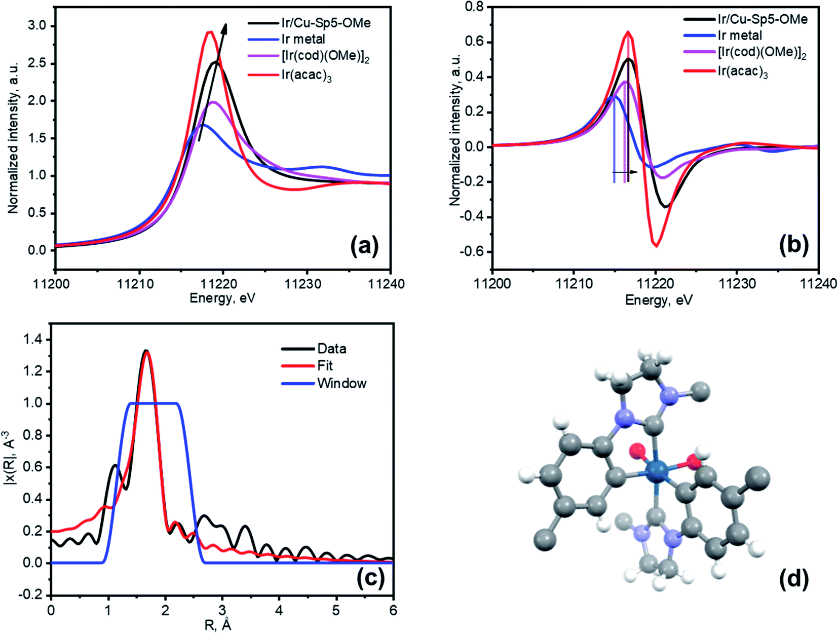 | ||
| Fig. 4 (a) XANES spectra of Ir/Cu-Sp5-OMe compared to Ir metal, [Ir(cod)(OMe)2] and Ir(acac)3 references, (b) First derivative of the XANES spectra from (a) and (c) Fitted EXAFS spectrum of Ir/Cu-Sp5-OMe in R-space (d) A model of iridium arrangement in Ir/Cu-Sp5-OMe. Atom colors: Ir, dark blue; C, grey; O, red; N, blue; H, white. The BF4− ions were omitted for clarity. While it cannot be modeled, based on the chemical species and their concentration in the reaction, it is expected that the two additional coordination sites on the Ir(III) complex, currently represented by O species, is likely to be two THF molecules. | ||
Next, HAADF-STEM was employed to visualize the iridium distribution in the material (Fig. S29†). The analysis revealed numerous, homogeneously distributed features with sizes up to 1 nm. While the smallest features are clearly described as single Ir atoms, the larger ones require further explanation. It is noted that EXAFS data indicate no noticeable contribution from Ir–Ir scattering, thus ruling out the formation of small Ir clusters. Further, given the layered structure of the Ir/Cu-Sp5-OMe material, the crystal is most likely observed along the a axis. Thus, it is thought that the larger features stem from iridium atoms in subsequent layers that also scatter and, hence, give rise to bright spots that appear to be larger than an individual atom. This goes in line with the increase in the density of single atom features in the darker regions of the image, where the material thickness and, therefore, the number of observed layers are much smaller.53
Having firmly established the nature of the iridium grafting in the material, catalytic investigations were subsequently carried out. For this, stilbene hydrogenation using hydrogen gas under mild reaction conditions was used as proof of heterogeneous catalytic activity (Scheme 2). The results of the catalytic runs are presented in Table 1 (NMR data in Fig. S30–S36†). Both Cu-Sp5-BF4-A and Cu-Sp5-OMe are not active in the reduction reaction even at a high pressure of 10 bar (Table 1, entry 1 and 2), indicating that iridium is responsible for the reaction progression. Expectedly, Ir/Cu-Sp5-OMe has a higher catalytic activity versusIr/Cu-Sp5-BF4-A due to the aforementioned diffusion issues, lower iridium loading, and a more polar pore environment in the latter (Table 1, entry 3 and 4). Moreover, to probe whether the reaction was truly heterogeneous in nature, both Ir-containing catalysts were subjected to a separation test where the catalyst was removed after a given time, and the reaction was allowed to proceed under the same reaction conditions (Fig. S37†). There was no additional stilbene conversion observed after the removal of the catalyst via filtration, implying that the catalytically active Ir species are indeed appended to the MOF. It is noted that the catalytic activity of Ir/Cu-Sp5-OMe, compared to other heterogeneous Ir-NHC materials (see Table S4†), is slightly lower (higher pressure needed for a full conversion in 24 h), which could be linked to the coordination environment of the NHC-Ir active site, which in this case is a bis-cyclometalated species. Also, as observed for other Ir-NHC systems,39 the Ir-containing catalysts are not recyclable as neither offered any conversion on the second run (Table 1, 5 and 6). To gain insight into the catalyst deactivation, Ir/Cu-Sp5-OMe was analyzed after the catalytic reaction via HAADF-STEM, XANES, EXAFS, and XPS. The XPS spectrum indicates a notable contribution of surface Ir(0) to the spectrum (Fig. S38 and Table S4†). This is corroborated by XANES, where a simultaneous decrease of the white line intensity (Fig. S39a†), as well as an edge shift to energies that are lower than that of Ir(I) is observed (Fig. S39b†); this indicates the presence of Ir(0) in the bulk of the material as well. Additionally, the EXAFS spectrum of Ir/Cu-Sp5-OMe after catalysis presents a clear feature at larger R distances, which corresponds to the Ir–Ir bonds in the metallic state (Fig. S40†), and HAADF-STEM images show an aggregation of iridium to nanoparticles with sizes up to 5 nm (Fig. S41†). These results indicate that, upon the use of the material in catalysis, iridium is reduced and aggregated to form larger particles, which are not as active as the fresh catalyst. Some part of iridium, however, is still coordinated to the MOF backbone as the peak at lower R in EXAFS is still present. Importantly, it was no longer possible to describe EXAFS data at lower R values using a bis-cyclometalated Ir(III) complex, indicating a change in the speciation of the coordinated iridium. While the exact nature of the active site is hard to determine, due to a change in iridium speciation over the course of the reaction, the present results do indicate the better suitability of the turbostratic Cu-Sp5-OMe when compared to Cu-Sp5-BF4-A for the preparation of grafted metal-NHC catalysts.
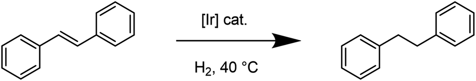 | ||
| Scheme 2 Stilbene hydrogenation reaction. | ||
| # | Material | Cat. mol% | P(H2), bar | Time, h | NMR yield, % |
|---|---|---|---|---|---|
| a Second catalytic run. | |||||
| 1 | Cu-Sp5-BF4-A | 7.5 (Cu) | 10 | 18 | 0 |
| 2 | Cu-Sp5-OMe | 7.5 (Cu) | 10 | 18 | 0 |
| 3 | Ir/Cu-Sp5-BF4-A | 0.25 | 5 | 24 | 66(1) |
| 4 | Ir/Cu-Sp5-OMe | 0.25 | 5 | 24 | 99(1) |
| 5 | Ir/Cu-Sp5-BF4-A | 0.25 | 5 | 24 | 0 |
| 6 | Ir/Cu-Sp5-OMe | 0.25 | 5 | 24 | 0 |
3. Conclusions
In this work, a new metal–organic framework, referred to as Cu-Sp5-BF4-EtOH, featuring a large channel-like structure with abundant NHC·HBF4 (NHC = N-heterocyclic carbene) species, was designed. The material was subsequently activated, a process that induced a transformation forming a new structure, denoted Cu-Sp5-BF4-A. The unexpected structural change is driven by the removal of ethanol molecules that were originally coordinated to Cu(II) ions in the parent MOF. Moreover, to prove that the NHC sites on the ligand backbone are accessible, Cu-Sp5-BF4-A was post-synthetically modified with sodium methoxide, leading to a change in the charge of the MOF ligand and an overall reduction in the dimensionality of the material from a 3-D porous structure to a layered 2D turbostratic phase, denoted Cu-Sp5-OMe. Next, both Cu-Sp5-BF4-A and Cu-Sp5-OMe were further modified with iridium forming an Ir–NHC adduct. Using a combination of XPS and EXAFS, it was found that this modification leads to the formation of bis-cyclometalated Ir(III) complexes inside the MOF pores. It was further demonstrated that the iridium loading and hence catalytic performance in a model reaction of stilbene hydrogenation is improved if the turbostratic Cu-Sp5-OMe is used as the iridium support rather than the non-turbostratic parent Cu-Sp5-BF4-A. This observation is owed to the presence of defects in the former, which is thought to lead to easier access to the NHC functionality inside the MOF pores. It is hoped that this work, which gives the first example of a MOF structure having accessible, saturated NHC-based functionality, can provide insight into the future design of new and improved metal–organic frameworks having utility in NHC-based chemistry.Data availability
Data for this paper, including raw files for all the plots in the manuscript and the ESI,† are available at Zenodo at https://doi.org/10.5281/zenodo.6543141Author contributions
IK and WLQ designed the work, IK synthesized the major part of the materials and performed catalysis and most of the characterization, AJ synthesized materials and performed characterization, MA performed isosteric heat of adsorption calculation, SY and VK contributed to the catalysis part, TS and MM performed XPS analysis and the fits, VK, TS and MA collected the XAS data, DS performed the EXAFS fitting, EO performed HAADF-STEM characterization. IK analyzed the data, IK and WLQ wrote the manuscript.Conflicts of interest
There are no conflicts to declare.Acknowledgements
Part of this work was supported by the Swiss National Science Foundation under grant number PYAPP2_160581. We acknowledge the Swiss-Norwegian Beamlines BM01 and BM31 at European Synchrotron Radiation Facility for the beamtime allocation for XRD and XAS measurements, respectively. M. A. acknowledges a fellowship from the Swiss National Science Foundation (P2ELP2_195134). We thank Dr Dmitry Chernyshov, Dr Iurii Dovgaliuk and Dr Vadim Diadkin for their assistance at ESRF. We thank Dr Claudia Avalos for performing the solid-state 13C NMR measurements, and Dr Pascal Schouwink for useful discussions.References
- M. Eddaoudi, J. Kim, N. Rosi, D. Vodak, J. Wachter, M. O'Keeffe and O. M. Yaghi, Science, 2002, 295, 469–472 CrossRef CAS PubMed.
- V. V. Karve, D. T. Sun, O. Trukhina, S. Yang, E. Oveisi, J. Luterbacher and W. L. Queen, Green Chem., 2020, 22, 368–378 RSC.
- M. Asgari, R. Semino, P. Schouwink, I. Kochetygov, O. Trukhina, J. D. Tarver, S. Bulut, S. Yang, C. M. Brown, M. Ceriotti and W. L. Queen, Eur. J. Inorg. Chem., 2019, 2019, 1147–1154 CrossRef CAS.
- M. Asgari, S. Jawahery, E. D. Bloch, M. R. Hudson, R. Flacau, B. Vlaisavljevich, J. R. Long, C. M. Brown and W. L. Queen, Chem. Sci., 2018, 9, 4579–4588 RSC.
- M. Asgari, R. Semino, P. A. Schouwink, I. Kochetygov, J. Tarver, O. Trukhina, R. Krishna, C. M. Brown, M. Ceriotti and W. L. Queen, Chem. Mater., 2020, 32, 1526–1536 CrossRef CAS PubMed.
- K. S. Park, Z. Ni, A. P. Côté, J. Y. Choi, R. Huang, F. J. Uribe-Romo, H. K. Chae, M. O'Keeffe and O. M. Yaghi, Proc. Natl. Acad. Sci., 2006, 103, 10186–10191 CrossRef CAS PubMed.
- H. Furukawa, N. Ko, Y. B. Go, N. Aratani, S. B. Choi, E. Choi, A. Ö. Yazaydin, R. Q. Snurr, M. O'Keeffe, J. Kim and O. M. Yaghi, Science, 2010, 329, 424–428 CrossRef CAS PubMed.
- H. Deng, S. Grunder, K. E. Cordova, C. Valente, H. Furukawa, M. Hmadeh, F. Gándara, A. C. Whalley, Z. Liu, S. Asahina, H. Kazumori, M. O'Keeffe, O. Terasaki, J. F. Stoddart and O. M. Yaghi, Science, 2012, 336, 1018–1023 CrossRef CAS PubMed.
- M. Bahadori, S. Tangestaninejad, M. Moghadam, V. Mirkhani, A. Mechler, I. Mohammadpoor-Baltork and F. Zadehahmadi, Microporous Mesoporous Mater., 2017, 253, 102–111 CrossRef CAS.
- X. Zhang, Y. Jiang and H. Fei, Chem. Commun., 2019, 55, 11928–11931 RSC.
- X. Zhang, J. Sun, G. Wei, Z. Liu, H. Yang, K. Wang and H. Fei, Angew. Chem., Int. Ed. Engl., 2019, 58, 2844–2849 CrossRef CAS PubMed.
- Y. Jiang, Y. Yu, X. Zhang, M. Weinert, X. Song, J. Ai, L. Han and H. Fei, Angew. Chem., Int. Ed., 2021, 60, 17388–17393 CrossRef CAS PubMed.
- B. An, L. Zeng, M. Jia, Z. Li, Z. Lin, Y. Song, Y. Zhou, J. Cheng, C. Wang and W. Lin, J. Am. Chem. Soc., 2017, 139, 17747–17750 CrossRef CAS PubMed.
- C. I. Ezugwu, N. A. Kabir, M. Yusubov and F. Verpoort, Coord. Chem. Rev., 2016, 307, 188–210 CrossRef CAS.
- R. Zhong, A. C. Lindhorst, F. J. Groche and F. E. Kühn, Chem. Rev., 2017, 117, 1970–2058 CrossRef CAS PubMed.
- D. J. Nelson and S. P. Nolan, Chem. Soc. Rev., 2013, 42, 6723–6753 RSC.
- S. Leuthausser, D. Schwarz and H. Plenio, Chemistry, 2007, 13, 7195–7203 CrossRef PubMed.
- J. C. Y. Lin, R. T. W. Huang, C. S. Lee, A. Bhattacharyya, W. S. Hwang and I. J. B. Lin, Chem. Rev., 2009, 109, 3561–3598 CrossRef CAS PubMed.
- S. Fantasia, J. L. Petersen, H. Jacobsen, L. Cavallo and S. P. Nolan, Organometallics, 2007, 26, 5880–5889 CrossRef CAS.
- Z. J. Wang, W. R. Jackson and A. J. Robinson, Green Chem., 2015, 17, 3407–3414 RSC.
- A. Aidouni, S. Bendahou, A. Demonceau and L. Delaude, J. Comb. Chem., 2008, 10, 886–892 CrossRef CAS PubMed.
- K. M. Kuhn and R. H. Grubbs, Org. Lett., 2008, 10, 2075–2077 CrossRef CAS PubMed.
- S. Díez-González, N. Marion and S. P. Nolan, Chem. Rev., 2009, 109, 3612–3676 CrossRef PubMed.
- I. Kochetygov, S. Bulut, M. Asgari and W. L. Queen, Dalton Trans., 2018, 47, 10527–10535 RSC.
- S. Bulut and W. L. Queen, J. Org. Chem., 2018, 83, 3806–3818 CrossRef CAS PubMed.
- F. Carson, E. Martínez-Castro, R. Marcos, G. G. Miera, K. Jansson, X. Zou and B. Martín-Matute, Chem. Commun., 2015, 51, 10864–10867 RSC.
- C. Y. Wang, P. Ray, Q. Gong, Y. Zhao, J. Li and A. D. Lueking, Phys. Chem. Chem. Phys., 2015, 17, 26766–26776 RSC.
- L. N. McHugh, M. J. McPherson, L. J. McCormick, S. A. Morris, P. S. Wheatley, S. J. Teat, D. McKay, D. M. Dawson, C. E. F. Sansome, S. E. Ashbrook, C. A. Stone, M. W. Smith and R. E. Morris, Nat. Chem., 2018, 10, 1096–1102 CrossRef CAS PubMed.
- J. Y. Lee, J. M. Roberts, O. K. Farha, A. A. Sarjeant, K. A. Scheidt and J. T. Hupp, Inorg. Chem., 2009, 48, 9971–9973 CrossRef CAS PubMed.
- D. X. Xue, A. J. Cairns, Y. Belmabkhout, L. Wojtas, Y. Liu, M. H. Alkordi and M. Eddaoudi, J. Am. Chem. Soc., 2013, 135, 7660–7667 CrossRef CAS PubMed.
- L. Kong, R. Zou, W. Bi, R. Zhong, W. Mu, J. Liu, R. P. S. Han and R. Zou, J. Mater. Chem. A, 2014, 2, 17771–17778 RSC.
- S. Sen, S. Neogi, A. Aijaz, Q. Xu and P. K. Bharadwaj, Inorg. Chem., 2014, 53, 7591–7598 CrossRef CAS PubMed.
- S. Csihony, D. A. Culkin, A. C. Sentman, A. P. Dove, R. M. Waymouth and J. L. Hedrick, J. Am. Chem. Soc., 2005, 127, 9079–9084 CrossRef CAS PubMed.
- J. Jang, Y. T. Nam, D. Kim, Y.-J. Kim, D. W. Kim and H.-T. Jung, J. Mater. Chem. A, 2020, 8, 8292–8299 RSC.
- S. Jin, B. Chung, H. J. Park, B. V. Cunning, J. H. Lee, A. Yoon, M. Huang, H. Seo, D. Lee, Z. Lee, R. S. Ruoff and S. Ryu, Adv. Funct. Mater., 2020, 30, 2005381 CrossRef CAS.
- J. Wang, N. Salim, B. Fox and N. Stanford, Appl. Mater. Today, 2017, 9, 196–203 CrossRef.
- C. Binder, T. Bendo, G. Hammes, G. O. Neves, R. Binder, J. D. B. de Mello and A. N. Klein, Carbon, 2017, 124, 685–692 CrossRef CAS.
- C. F. Rentzsch, E. Tosh, W. A. Herrmann and F. E. Kuhn, Green Chem., 2009, 11, 1610–1617 RSC.
- I. Romanenko, D. Gajan, R. Sayah, D. Crozet, E. Jeanneau, C. Lucas, L. Leroux, L. Veyre, A. Lesage, L. Emsley, E. Lacote and C. Thieuleux, Angew. Chem., Int. Ed. Engl., 2015, 54, 12937–12941 CrossRef CAS PubMed.
- V. Adamovich, P.-L. T. Boudreault, M. A. Esteruelas, D. Gómez-Bautista, A. M. López, E. Oñate and J.-Y. Tsai, Organometallics, 2019, 38, 2738–2747 CrossRef CAS.
- M. A. Esteruelas, A. M. López, E. Oñate, A. San-Torcuato, J.-Y. Tsai and C. Xia, Inorg. Chem., 2018, 57, 3720–3730 CrossRef CAS PubMed.
- S. B. Rubashkin, W.-Y. Chu and K. I. Goldberg, Organometallics, 2021, 40, 1296–1302 CrossRef CAS.
- P. V. Dau and S. M. Cohen, Chem. Commun., 2013, 49, 6128–6130 RSC.
- P. V. Dau, M. Kim and S. M. Cohen, Chem. Sci., 2013, 4, 601–605 RSC.
- Y. You, J. Chin. Chem. Soc., 2018, 65, 352–367 CrossRef CAS.
- L. M. Cañada, J. Kölling and T. S. Teets, Polyhedron, 2020, 178, 114332 CrossRef.
- Y. You, S. Cho and W. Nam, Inorg. Chem., 2014, 53, 1804–1815 CrossRef CAS PubMed.
- C. E. Welby, L. Gilmartin, R. R. Marriott, A. Zahid, C. R. Rice, E. A. Gibson and P. I. P. Elliott, Dalton Trans., 2013, 42, 13527–13536 RSC.
- A. B. Tamayo, S. Garon, T. Sajoto, P. I. Djurovich, I. M. Tsyba, R. Bau and M. E. Thompson, Inorg. Chem., 2005, 44, 8723–8732 CrossRef CAS PubMed.
- M. N. Hopkinson, C. Richter, M. Schedler and F. Glorius, Nature, 2014, 510, 485–496 CrossRef CAS PubMed.
- Y. Zhou, J. Jia, W. Li, H. Fei and M. Zhou, Chem. Commun., 2013, 49, 3230–3232 RSC.
- H. Tsurugi, S. Fujita, G. Choi, T. Yamagata, S. Ito, H. Miyasaka and K. Mashima, Organometallics, 2010, 29, 4120–4129 CrossRef CAS.
- E. A. Sutter and P. W. Sutter, J. Am. Chem. Soc., 2014, 136, 16865–16870 CrossRef CAS PubMed.
Footnote |
| † Electronic supplementary information (ESI) available: General notes, synthetic protocols, catalysis protocols, crystallographic data, X-ray structures and powder pattern, TGA curves, FTIR spectra, adsorption isotherms, NMR spectra, optical and electron microscope images, XAS and XPS spectra, EXAFS fitting details. CCDC 2128529, 2128530. For ESI and crystallographic data in CIF or other electronic format see https://doi.org/10.1039/d2sc01041k |
| This journal is © The Royal Society of Chemistry 2022 |