 Open Access Article
The luminous frontier: transformative NIR-IIa fluorescent polymer dots for deep-tissue imaging
Richardson
Lawrance
 a,
Partha
Chowdhury
 b,
Hong-Cheu
Lin
*ac and
Yang-Hsiang
Chan
 *bcd
*bcd
aDepartment of Materials Science and Engineering, National Yang Ming Chiao Tung University, Hsinchu, 30050 Taiwan. E-mail: richardsonlawrance.chemie@gmail.com; linhc@nycu.edu.tw
bDepartment of Applied Chemistry, National Yang Ming Chiao Tung University, Hsinchu, 30050 Taiwan. E-mail: yhchan@nycu.edu.tw
cCenter for Emergent Functional Matter Science, National Yang Ming Chiao Tung University, Hsinchu, 30050 Taiwan
dDepartment of Medicinal and Applied Chemistry, Kaohsiung Medical University, Kaohsiung, 80708 Taiwan
First published on 10th June 2024
Abstract
In the realm of deep-tissue imaging, fluorescence imaging in the second near-infrared window (NIR-II, 1000–1700 nm) has proved to be an emerging tool, allowing scientists to probe biological processes with unprecedented depth. Within the NIR-II window, the NIR-IIa region (1300–1400 nm) has proved to have excellent imaging quality in the NIR-II window. Among the diverse types of NIR-II fluorophores, polymer dots (Pdots) have surfaced as a unique category of probes due to their exceptional properties including exorbitant brightness, excellent photostability, outstanding water dispersibility, and facile structural modification compared to traditional fluorescent molecules. The utilization of NIR-IIa Pdots has also addressed critical limitations in imaging by utilizing the advantages of reduced light scattering, diminished autofluorescence, and decreased light absorption by biospecies. Realizing such remarkable characteristics, this review offers insights into the design of high-performance NIR-IIa Pdots through a comprehensive interplay between chemical structures, photophysical properties, and their application in deep-tissue imaging.
1. Introduction
Fluorescence imaging stands out as a pivotal tool in biomedical detection and image-guided surgery that has opened a new window for both fundamental research and clinical practices in the last few decades. Unlike traditional imaging techniques, such as computed tomography (CT),1–3 magnetic resonance imaging (MRI),3,4 ultrasound (US),5,6 positron emission tomography (PET),7 and single-photon emission CT (SPECT),8,9 fluorescence imaging offers distinct advantages such as non-invasiveness, exceptional spatiotemporal resolution, real-time detection capability and affordability.10 Over the years, fluorescence imaging has found wide-ranging applications spanning immunofluorescence assays,11 sensing,12,13 super-resolution imaging,14,15 single molecule imaging,16 3D imaging,17,18 and image-guided surgery.19–21 However, the obstacle hindering the advancement of fluorescence imaging stems from its spectral emission range, especially visible range, which suffers from enhanced tissue scattering and high autofluorescence, despite its widespread utilization in image-guided surgery both before and during the operation.20,22,23In recent years, there has been notable attention directed towards fluorescence imaging technology in the near-infrared spectrum, primarily because of its superior resolution, thereby enhancing the quality of in vivo imaging.24 However, within the first near-infrared region (NIR-I, 700–900 nm), imaging deep tissues still encounters significant limitations, of which the penetration depth only goes up to a few millimeters from approximately 1 to 6 mm.25–30 Fortunately, in 2009, Dai's pioneering research introduced a fresh perspective on bioimaging—an innovative optical range now known as the NIR-II window (1000–1700 nm) demonstrated superior performance in bioimaging.31–33 As shown in Fig. 1, the major advantages of the NIR-II window include reduced tissue scattering, and minimal autofluorescence compared to NIR-I, which results in improved imaging depths of approximately 5–20 mm.27,34 However, recent phantom studies, revealed that the contrast of in vivo imaging followed the water absorption trend, which could be beneficial for acquiring high resolution images. Emission wavelengths of >1300 nm, where water absorption plays a crucial role in enhancing the contrast over scattering in fluorescence images, result in a high signal to background ratio (SBR) and superior resolution.35,36 Overall, the dual benefits of longer wavelengths reducing background noise and water absorption contributing to contrast enhancement lead to better resolution in the 1300–1400 nm region, known as the NIR-IIa window.35,37,38 These advantages make NIR-IIa imaging particularly useful for numerous biomedical applications, including in vivo imaging and other medical assessments.35,37
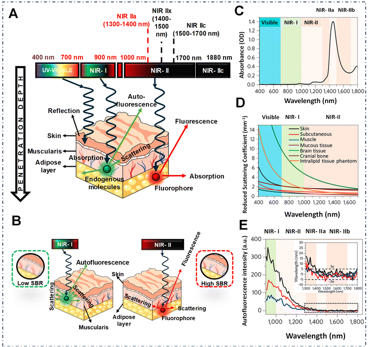 | ||
| Fig. 1 (A) Schematic depiction illustrating the interaction between light and biological tissues across a range of wavelengths. (B) Schematic representation of the propagation of light showing lower (on the left) and intermediate (on the right) absorption characteristics within biological tissue, and the resultant SBRs in fluorescence imaging. (C) Water absorption spectrum within the range of 400–1800 nm. (D) Decreased scattering coefficients among various biological tissues and intralipid tissue mimics. (E) Spectrum of autofluorescence observed in mouse liver, spleen, and heart tissue under excitation at 808 nm shown as black, red and blue lines respectively. The inset displays a closer look at the results for longer wavelengths. Reproduced from ref. 39 with permission from, American Chemical Society. Copyright © 2020. | ||
Since then, fluorophores emitting in the NIR-IIa window or at longer wavelengths have become a cornerstone of fluorescence imaging. Lately, significant efforts have been undertaken to create fluorophores with emission beyond 1300 nm; this includes single-walled carbon nanotubes (SWCNTs),31,37 quantum dots (QDs),40–43 rare earth-doped nanoparticles (RENPs),44–46 small molecule dyes (SMDs),47 and organic semiconducting polymer-based nanoparticles (SPs).48–51 However, each has unique benefits and drawbacks that should be carefully considered for certain biomedical imaging applications.18,33,52 NIR-IIa organic dyes outperform inorganic based fluorophores in many aspects, such as facile structural modification and good biocompatibility, low levels of cytotoxicity, suitability for extensive chemical synthesis, and ease of modification.38 However, NIR-IIa organic compounds have highly conjugated scaffolds that contribute to their low water solubility, so encasing dyes in amphiphilic surfactants inside the nanoparticles has been a popular way to get around this problem. Nevertheless, for small organic dye-doped nanoparticles, potential leakage from the encapsulating matrix is still a problem. Hence, polymer dots (Pdots) have been developed as an innovative type of probe that represents a purely organic class of water-suspendible polymeric nanoparticles typically composed of conjugated polymers or organic dyes embedded within an amphiphilic polymeric matrix. Their highly tuneable optical properties, extraordinary brightness, enhanced photostability, and biocompatibility make them superior to traditional inorganic fluorophores and small molecules.53–55 Generally, Pdots can be prepared through various methods, including nanoprecipitation, mini-emulsion polymerization, the self-assembly of amphiphilic block copolymers, or employing a microfluidic technique.56–58 Pdots are becoming increasingly recognized as a highly promising category of fluorescent probes, offering great potential for analysis and imaging applications in the field of biology.52,59–61 Unfortunately, to date, there remains a scarcity of Pdots exhibiting emission maxima within the NIR-IIa range.49,62–65 This limitation is attributed to the energy gap principle, which indicates that nonradiative decay processes are expedited through vibrational interactions between the ground and excited states due to the narrow energy gap, and hence, a very low quantum yield (QY).60,66 However, these limitations can be overcome if the molecular design follows the right fundamental design strategy, which is described in detail in the later part of this review.
In this review, we highlight the most recent developments in Pdots emitting in the NIR-IIa range. Moreover, we discuss existing molecular scaffolds and the strategies to extend the emission wavelengths to the NIR-IIa window. Next, the fundamental obstacle of this window, i.e., brightness, is thoroughly discussed throughout the manuscript. We separately elaborate the two classes of organic dyes (small molecules and Pdots) and their advantages/disadvantage in terms of bio-imaging applications. Finally, the potential application of NIR-IIa fluorophores in blood vessels and tumour imaging is compared with NIR-II dyes with emission <1300 nm and systematically explained for a better understanding of the advantages of the NIR-IIa region over other imaging windows. Last but not least, we mention the possible challenges and future outlook that could be impactful for the future development of NIR-IIa fluorophores, to the best of our knowledge.
2. Molecular engineering of organic fluorophores to attain NIR-IIa emission
NIR-IIa emissive fluorophores in the 1300–1400 nm region are a significant development that overcomes the drawbacks of NIR-I and NIR-II and opens the door to previously unattainable depths in non-invasive imaging and diagnostic applications.61 In this context, NIR-IIa organic fluorophores, comprising both small molecules and semiconducting polymers, have attracted considerable attention owing to their excellent biocompatibility, versatile molecular design, and the ability to finely tune their optical properties.38 Until now, numerous methodologies have been systematically employed to intricately modify the chemical backbones of organic fluorophores (Fig. 2). These strategic modifications aim to extend the spectral range, enabling desirable absorption and emission of light at longer wavelengths.67 Conventionally, the engineering of these fluorophores is contingent upon the difference in energy between the highest occupied molecular orbital (HOMO) and the lowest unoccupied molecular orbital (LUMO), a correlation intricately governed by their π-conjugated systems.66,68 Practical approaches for molecular engineering, which include the extension of conjugation,52,67 enhancement of electron density in donor units,69 reduction of electron density in acceptor units,70 heteroatom exchange,71 and J-aggregate formation,72 have surfaced as efficacious strategies for inducing a redshifted absorption/emission wavelength of a given fluorophore. For example, extension of the conjugation chain length delocalizes π electrons into the molecular backbone, resulting in a redshift of both absorption and emission due to reducing the HOMO–LUMO gap.49,73,74 To further manipulate the electron density of donor units, ingenious approaches involving the introduction of electron-donating substituents have been successfully employed.69 Concurrently, strategies for diminishing the electron density of acceptor units have been explored, including tactics such as exploiting the heavy atom effect (e.g., substituting O for Si, S for Se), integrating electron-withdrawing substituents, and introducing fluorine atoms.71,75 These meticulous adjustments are instrumental in sculpting the desired properties of fluorophores. The incorporation/replacement of heteroatoms into the fluorophore structure stands out as a pivotal avenue for modulating electron density and, consequently, influencing the energy gap. This deliberate modification manifests as bathochromic shifts in absorption and emission wavelengths. Specifically, substituting the oxygen atom of a heterocycle for a carbon, silicon or other chalcogen atom emerges as a particularly effective strategy, inducing a discernible redshift in the absorption/emission spectrum.71 Furthermore, the creation of J-aggregates emerges as an intriguing facet in this scientific narrative. These aggregates, fabricated through the judicious aggregation of monomer fluorophores via π–π interactions between adjacent conjugated units, exhibit redshifted absorption and emission. This distinctive feature underscores the potential of J-aggregates as a valuable tool for achieving desired shifts in spectral characteristics.72,76 Together, these strategic modifications form a comprehensive framework for meticulously fine-tuning the chemical properties inherent in organic fluorophores, allowing for longer wavelength shifts.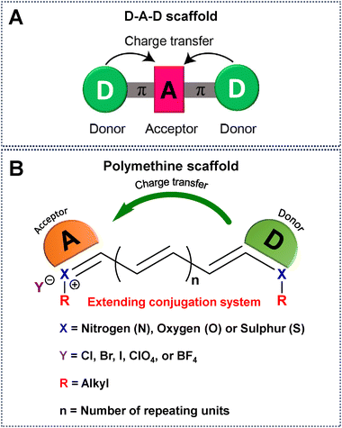 | ||
| Fig. 2 Schematic representation of a universal scaffold for (A) D–A–D and (B) polymethine based fluorophores. | ||
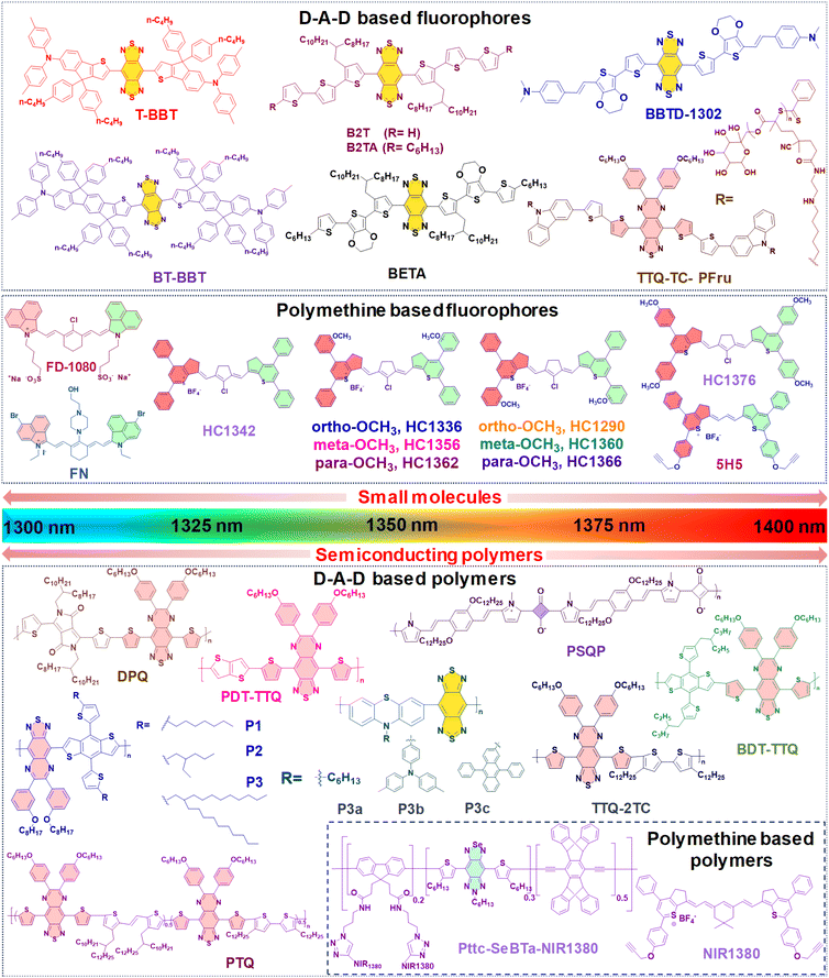
Until now, NIR-IIa organic fluorophores have been categorized into two groups: (1) fluorophores based on a (donor–acceptor–donor) D–A–D structure and (2) fluorophores based on polymethine structures. The first category comprises fluorophores structured on the (donor–acceptor–donor) D–A–D architecture, where an acceptor unit is strategically nestled between two donor entities. This intricate design, illustrated in Fig. 2A, demands meticulous consideration in selecting electron donors, acceptors, and π-bridging groups.50,77 Researchers have created diverse polymer backbones based on the D–A–D framework, utilizing various functional units such as D–A–D, D–π–A–A–D, S–D–π–π–π–Dn–S (with a π-spacer and S-shielding unit), and D–S–A.78 On the other hand, polymethine fluorophores consist of two heterocyclic rings, incorporating heteroatoms like nitrogen, oxygen, or sulfur atoms (Fig. 2B).79 One of these heterocyclic rings carries a positive charge and is connected by conjugation with an odd number of carbon atoms. The terminal group of the heterocycle with a positive charge acts as an electron acceptor, whereas the other serves as an electron donor.77 Both categories, D–A–D and polymethine, showcase bathochromic shifts in absorption/emission by strategically manipulating their band gap levels. Fig. 3 visually articulates the chemical structures of recently developed small molecules within these categories, alongside semiconducting polymers, while Table 1 provides a concise summary of their photophysical properties. This section predominantly focuses on the intentional design of organic fluorophores exhibiting NIR-IIa emission.
| Type | Label | Amphiphilic polymer | λ abs/λem (nm) | QY (%) | Size (nm) | Ref. |
|---|---|---|---|---|---|---|
| a Measured in DCM. b Measured in DMSO. c Measured in THF. d Measured in water. e Measured in MeOH. f Measured in PBS. g Measured in DCE. h Measured in ACN. | ||||||
| Small molecules | T-BBT | DSPE–mPEG2000 | 982/1307a | 3.6a | 81.5 | 80 |
| BT-BBT | DSPE–mPEG2000 | 960/1246a | 13.5a | 70 | ||
| BBTD-1302 | DSPE–mPEG5000 | 942/1302b | 2.4b | 80 | 81 | |
| TTQ-TC-PFru | — | 796/1042c, 1100d, 1300c | 5.4c, 0.6d | 60 | 82 | |
| B2T | Pluronic-F127 | 871/1123, 1300d | 0.012d | 111.4 | 83 | |
| B2TA | Pluronic-F127 | 878/1127, 1300d | 0.016d | 107.8 | ||
| BETA | Pluronic-F127 | 892/1138, 1300d | 0.019d | 117.8 | ||
| FD-1080 | DMPC | 1360/1370e | 0.054f | 110 | 84 | |
| FN | Polypeptide PEA | 1116/1285b | 0.058e | 47 | 85 | |
| HC1342 | PEG-b-PCL | 1286/1342g | 0.015g | 32.1 | 62 | |
| HC1336 | PEG-b-PCL | 1276/1336g | 0.012g | — | ||
| HC1356 | PEG-b-PCL | 1288/1356g | 0.010g | — | ||
| HC1362 | PEG-b-PCL | 1298/1362g | 0.011g | — | ||
| HC1290 | PEG-b-PCL | 1232/1290g | 0.010g | — | ||
| HC1360 | PEG-b-PCL | 1290/1360g | 0.009g | — | ||
| HC1366 | PEG-b-PCL | 1306/1366g | 0.010g | — | ||
| HC1376 | PEG-b-PCL | 1312/1376g | 0.011g | — | ||
| 5H5 | PEG/N3–PEG8–cRGDfk | 1069/1125, 1300h | 2.6g | 50 | 86 | |
| Organic semi-conducting polymers | DPQ | DSPE–PEG5000–FA | 1015/1300c | 0.02c | 100 | 63 |
| BDT-TTQ | Pluronic-F127 | 1066/1305c | — | 100 | 87 | |
| P1 | — | 1078/1151d | 0.322c | — | 88 | |
| P2 | — | 1080/1151d | 0.384c | — | ||
| P3 | DSPE–PEG | 1100/1![[thin space (1/6-em)]](https://www.rsc.org/images/entities/char_2009.gif) 150 150![[thin space (1/6-em)]](https://www.rsc.org/images/entities/char_2009.gif) 1300d 1300d |
0.505c | 182.7 | ||
| P3a | PS–PEG | 736/1113, 1284c | 0.1d | 24 | 48 | |
| P3b | PS–PEG | 759/1115, 1279c | 0.6d | 14 | ||
| P3c | PS–PEG | 746/1123, 1272c | 1.7d | 16 | ||
| PSQP | DSPE–PEG5000–FA | 748/1300c | — | 172.4 | 64 | |
| PTQ | DSPE–PEG2000–AS1411 liposomes | 840/1310c | — | 100 | 89 | |
| TTQ-2TC | PS–PEG | 880/1![[thin space (1/6-em)]](https://www.rsc.org/images/entities/char_2009.gif) 070 070![[thin space (1/6-em)]](https://www.rsc.org/images/entities/char_2009.gif) 1270d 1270d |
0.3c | 140 | 90 | |
| PDT-TTQ | DSPE–PEG5000–COOH | 1000/1020, 1310c | — | 8 | 91 | |
| Pttc-SeBTa-NIR1380 | CM–PEG–DSPE | 1270/1380a | 0.25a | 73 | 49 | |
2.1. Molecular engineering of D–A–D based NIR-IIa emissive fluorophores
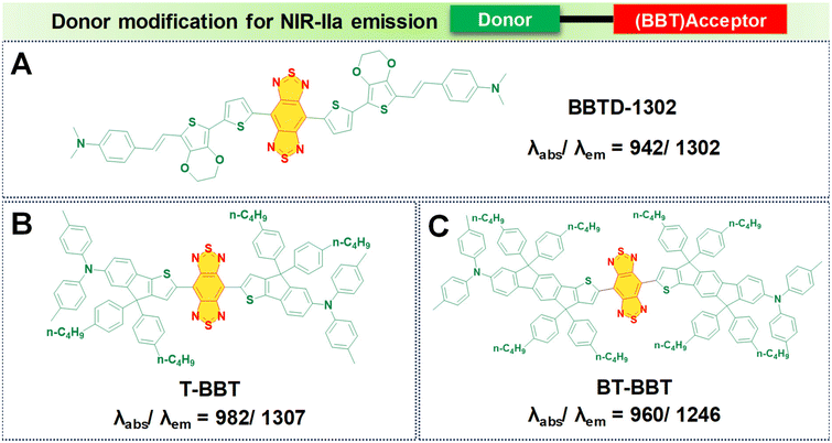
In the pursuit of developing NIR-IIa fluorophores, we conceptualize their design with a characteristic strong electron donor–acceptor (D–A) configuration. This design choice promotes significant separation between the electron density of the HOMO and the LUMO. A decrease in the energy gap between the HOMO and the LUMO typically leads to a redshifted wavelength. This is accomplished by employing electron acceptor units with strong electron-withdrawing capabilities, thereby lowering the LUMO level.50 Additionally, the incorporation of electron-rich donors with relatively large π-conjugated structures can enhance the intermolecular π–π interactions and facilitate intramolecular charge transfer (ICT).92 Besides, the introduction of molecular planarity is also an effective strategy for obtaining increased π-conjugation, thereby augmenting the extent of absorption and emission for the fluorophores.83 It is revealed that the torsional angle between molecular fragments directly affects the planarity of fluorescent dyes, which in turn influences their emission wavelength. There is a direct correlation between the transition wavelength of the first excited state and molecular planarity. Increasing the planarity by reducing the torsional angle leads to a redshift in the emission wavelength due to enhanced orbital overlap and reduced non-radiative decay pathways in planar structures.93–95 Therefore, understanding the relationship between torsional angle and emission wavelength is crucial for the rational design of fluorescent materials with desired photophysical properties. To illustrate the above phenomenon, we provide examples of various reported fluorophores that emit in the NIR-IIa region based on the D–A–D architecture.Research involving donor moieties featuring fused ring systems has garnered significant interest because of their rigid, planar structures, which promote intermolecular organization and effective charge transfer. Notably, examples such as 4,8-bis(4-(2-ethylpentyl)thiophen-2-yl)benzo[1,2-b:4,5-b′]dithiophene (BDT) and 2,5-bis(trimethylstannyl)thieno[3,2-b]thiophene (DT) have been investigated. In their respective studies, Fan et al. and Dai et al. designed unique polymer dots—BDT-TTQ Pdots87 (Fig. 4A, i) and PDT-TTQ Pdots91 (Fig. 4B, i). BDT-TTQ Pdots employed BDT as the donor, while PDT-TTQ Pdots utilized PDT as the donor and 6,7-bis(4-(hexyloxy)phenyl)-4,9-di(thiophen-2-yl)-[1,2,5]thiadiazolo[3,4-g]-quinoxaline (TTQ) as the common acceptor. The BDT-TTQ Pdots demonstrated an absorption peak at 1066 nm and an emission maximum in the NIR-IIa range at 1305 nm as shown in (Fig. 4A, ii), while the PDT-TTQ Pdots showed absorption at 1000 nm with an emission maximum at 1310 nm (Fig. 4B, ii). The incorporation of the planar dual-thiophene unit from the electron releasing DT and the alkylthiophene-substituted benzodithiophene group from the electron donor BDT imparted a more planar structure to the main chain of PDT-TTQ Pdots. Theoretical calculations also reveal that the optimized ground state planar configuration of the molecule maintains small torsional angles of less than 20° along the main chain. This enhanced planarity is expected to expand the absorption range of the polymer, attributed to the enhanced π-conjugation arising from the planar molecular structure. This is reflected in the decreased HOMO–LUMO gaps observed in the Pdots; this is 1.37 eV for PDT-TTQ. Recently, An et al. developed T-BBT (Fig. 5B) and BT-BBT (Fig. 5C) Pdots, achieving a planarized molecular conformation by integrating donor units (triarylamine and thiophene) with the cyclopenta-1,3-diene unit attached to the acceptor unit, m-benzo[1,2-c:4,5-c′]bis[1,2,5]thiadiazole (BBT), to form a rigid molecular entity.80 This strategic approach not only bolstered the electron-donating properties but also elevated the degree of π-conjugation. DFT calculations of the ground state optimised geometry showed that the torsional angle between the donor and acceptor units of both T-BBT and BT-BBT was 0° along the conjugated chain with a completely coplanar conformation. Driven by the strong ICT and extensive π-conjugation in both T-BBT and BT-BBT, they display narrow energy gaps of 1.039 and 1.042 eV, respectively. T-BBT and BT-BBT exhibited distinct absorption peaks at 982 nm and 960 nm, respectively, with emission peaks at 1307 nm and 1246 nm, respectively. T-BBT and BT-BBT exhibited substantial Stokes shifts of 325 nm and 286 nm, respectively, which were indicative of a strong ICT between the donor (D) and acceptor (A). Due to the stronger charge transfer characteristics of T-BBT, it exhibits longer-wavelength absorption and emission maximum peaks compared to those of BT-BBT.
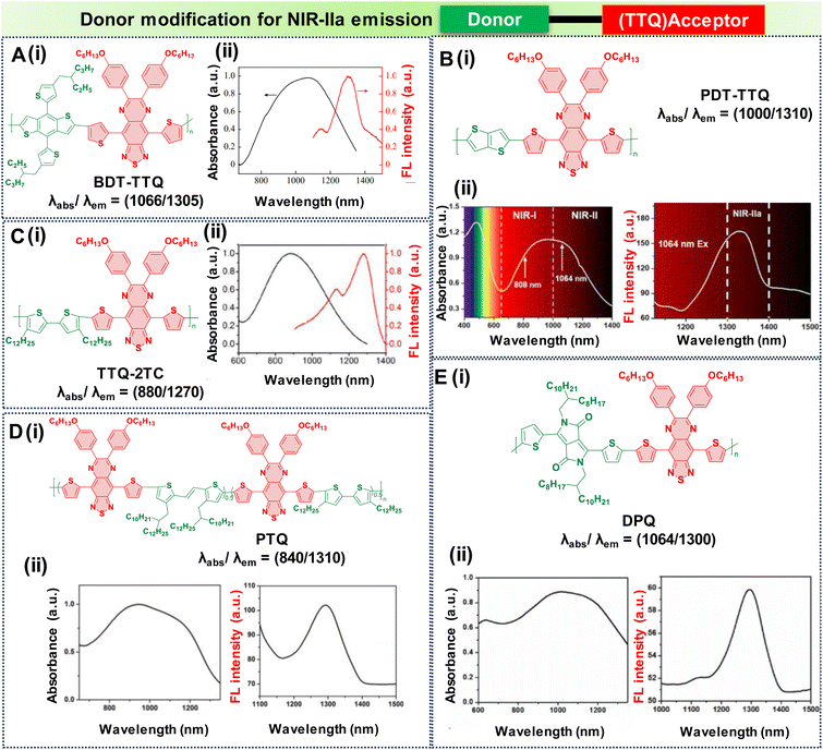 | ||
| Fig. 4 Donor modification for NIR-IIa emission with a TTQ acceptor core; molecular structures and the absorption and emission spectra of D–A–D based semiconducting polymers are as follows: (A) BDT-TTQ, (B) TTQ-2TC, (C) DPQ, (D) PTQ, (E) PDT-TTQ. Adapted with permission from ref. 63 and 89–91 from Elsevier, copyright © 2024, American Chemical Society, copyright © 2020, John Wiley and Sons, copyright © 2021, Elsevier, copyright © 2021 respectively. | ||
An alternative effective approach for achieving NIR-IIa fluorescence emission in D–A–D structures involves extending the conjugation along the thiophene donor units and diminishing the electron-withdrawing densities. This strategy enhances the charge transfer characteristics. Subsequently, the researchers designed TTQ-2TC Pdots (Fig. 4C, i).90
In this design, an electron donor is represented by a bithiophene unit with extended alkyl side chains, while TTQ is selected as the acceptor. Notably, these Pdots displayed absorption bands within the range of 600 to 1300 nm, indicative of ICT within the charge transfer states of D–A–D. TTQ-2TC displayed a broad absorption at 880 nm and a peak emission maximum at 1270 nm in water as shown in Fig. 4C, ii. Another modification involved altering the donor unit by incorporating structurally twisted donor moieties, specifically (E)-1,2-bis(3-tetradecyl-thiophen-2-yl)ethene (TV) and 4,4′′-di-n-dodecyl-2,2′′-bithiophene (2TC), which were further modified with extended alkyl side chains, along with TTQ as the acceptor unit. This alteration led to the formation of PTQ Pdots (Fig. 4D, i) capable of exhibiting absorption peaks at 840 nm, with an NIR-IIa fluorescence emission peak at 1300 nm as displayed in (Fig. 4D, ii).89 Utilizing diketopyrrolopyrrole (DPP), alternating with an electron rich oligothiophene as the donor and TTQ as the acceptor, Huang's research group developed DPQ Pdots (Fig. 4E, i).63 DPQ displayed absorption and emission peaks at 1064 nm and 1300 nm, respectively, as shown in Fig. 4E, ii. BBTD-1302 (Fig. 5) was developed by Ye et al., incorporating electron-rich thiophenes, a styrene moiety, and N,N-dimethylamino groups at both ends of the BBT core.81 Theoretical studies revealed a planar configuration of the two thiophene units consisting of styrene and benzene units. The HOMO of BBTD-1302 spans the entire conjugation skeleton, while the LUMO is located on both the BBT core and the bithiophene units. This indicates an ICT from the donor N,N-dimethylamino to the BBT acceptor core, leading to an energy gap of 0.88 eV. BBTD-1302 exhibits a strong absorption and NIR-IIa emission at 942 nm and 1302 nm respectively.
PSQP Pdots (Fig. 6B), incorporating a squaraine acceptor core and 1,4-bis[2-(1-methylpyrrol-2-yl)vinyl]-2,5-didodecyloxybenzene (BP) as the donor unit, exhibit a narrow HOMO–LUMO energy gap. This feature comes from the alternating use of strong donor and acceptor units, leading to longer conjugation in the polymer backbone. The semiconducting polymer PSQP presents a broad absorption at 748 nm and a redshifted emission reaching 1300 nm. In contrast, the small molecular form of the squaraine dye, SQP (Fig. 6A), fails to reach longer wavelengths due to its reduced conjugation compared to that of PSQP Pdots.64,98
 | ||
| Fig. 6 Donor modification for NIR-IIa emission using squaraine based acceptors with molecular structures of (A) SQP and (B) PSQP with their absorption and emission values. | ||
2.2. Molecular engineering of polymethine based NIR-IIa emissive fluorophores
Inspired by the structural characteristics of an FDA-approved NIR dye, indocyanine green (ICG), a series of polymethine dyes have been synthesized.96 These dyes also possess the unique property of both absorbing and emitting light within the NIR-IIa spectral range. As mentioned earlier, the structures of polymethine fluorophores have long conjugated methine units and two heterocyclic terminals that are either symmetric or asymmetric. Thus, utilizing extended methine units and a terminal unit that is electron-deficient could effectively extend the emission wavelength, resulting in remarkable in vivo penetration depth. However, as per the theoretical model, a cyanine with an extremely long chain and long wavelength would lack a significant gap between the HOMO and LUMO. This difference occurs because the more extended chain means that the terminal group's role becomes insignificant.97 Thus, the concept of the “cyanine limit” was introduced, indicating that molecules experienced symmetry disruption beyond a certain length.98 In general, elongating the polymethine chain tends to efficiently expand the π-conjugate system thereby reducing the HOMO–LUMO energy gap, which can have NIR-IIa emission. However, most of the polymethine fluorophores reported so far typically have only a maximum of seven methine units. This is attributed to a limitation known as the “cyanine limit”. Conversely, a thoughtful design focusing on heteroatom exchange and introducing donor groups at the heterocyclic terminals has proved to be successful for achieving a bathochromic shift towards longer wavelengths.99 Also, the unique chain structure and planarity of the heterocyclic terminals make polymethine fluorophores susceptible to a specific aggregation phenomenon in water, resulting in the formation of J-aggregates causing notable changes in the optical properties.72 These highly organized assemblies of organic dyes, compared to monomer molecules, exhibit spectroscopic characteristics such as bathochromically shifted absorption and emission, minimal Stokes shifts, and enhanced absorption coefficients, all achieved through self-assembly processes.72,100 Following this, we elaborate on the specific approach to extending wavelengths based on the principles outlined above.(a) Increasing the length of the conjugated chain. Extension of the polymethine conjugated chain predominantly involves increasing the number of methine units within the elongated chain. Our research team has successfully synthesized three polymethine dyes, namely NIR1125, NIR1270, and NIR1380 (Fig. 7).77 These dyes are characterized by a narrow-band feature achieved through expansion of the conjugation length using intermediate methine units. NIR1125 comprises three methine units, NIR1270 consists of five methine units, and NIR1380 incorporates seven methine units, each linked to thiopyrylium (an electron-releasing group) and thiopyrylium salt (an electron-withdrawing unit) at the terminals, as illustrated in Fig. 7A–C. As the number of methine units increased from three to seven, it resulted in a reduction in the HOMO–LUMO energy gap, as represented in Fig. 7D. The HOMO–LUMO gaps were measured for each dye individually: NIR1125 exhibited a gap of 1.59 eV, NIR1270 showed a reduced gap of 1.46 eV, and NIR1380 demonstrated the smallest gap of 1.36 eV. As a result, the reduction in the energy gap led to shifts towards longer wavelengths in both absorption and emission. NIR1125 displayed absorption and emission peaks at 1066 nm and 1125 nm, respectively. In the case of NIR1270, absorption and emission peaks are observed at 1188 nm and 1270 nm, respectively. Notably, the dye with seven methine units, NIR1380, exhibited absorption and NIR-IIa emission peaks at 1270 nm and 1380 nm as displayed in Fig. 7E and F. This sequential exploration of polymethine dyes with increasing methine units not only provided insights into their electronic structure but also demonstrated a systematic decrease in the energy gap, which enabled extension of the wavelengths into the NIR-IIa region.
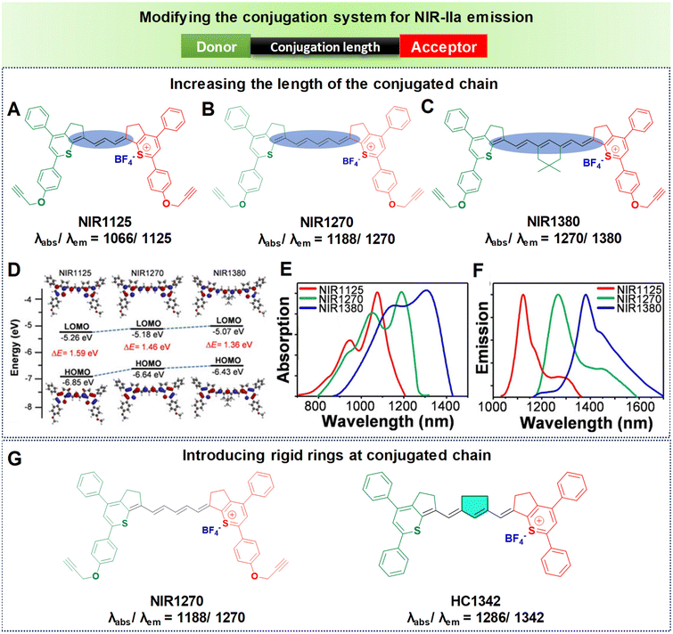 | ||
| Fig. 7 Enhancing the conjugation length to achieve NIR-IIa emission. Molecular structures of polymethine-based fluorophores (A) NIR1125, (B) NIR1270, and (C) NIR1380. (D) Computed HOMOs and LUMOs of the molecular fluorophores. (E) Absorption spectra in DCM: NIR1125, NIR1270, and NIR1380 shown as red, blue and green lines respectively. (F) Emission spectra in DCM: NIR1125, NIR1270, and NIR1380 shown as red, blue, and green lines respectively. Reproduced with permission from ref. 77 from John Wiley and Sons, Copyright © 2020. (G) Structures of NIR1270 and HC1342 showing redshifted NIR-IIa emission by introducing a rigid ring into the conjugated chain. | ||
(b) Introducing rigid rings into the conjugated chain. Despite the effectiveness of increasing the number of methine units to extend the emission wavelength in polymethines, the “cyanine limit” phenomenon poses challenges to the stable synthesis of longer-emitting fluorophores. Consequently, many researchers have sought to improve the fluorophore emission wavelengths by altering the chain structures while maintaining a consistent number of methine units. The predominant approach involves inserting a set of rigid rings into the central portion of the methine chain. Introducing a rigid ring into the methine unit helps to maintain a planar structure, which is crucial for efficient π-conjugation and leads to a longer emission wavelength due to the extended conjugation pathway. For example, as depicted in Fig. 7G, the introduction of a five-membered ring containing a nucleofugal chlorine group into the central chain bridge of NIR1270 dye resulted in a bathochromic shift of around 72 nm, producing HC1342 dye.62,77
(c) Extending the conjugation of the terminal moiety. An alternative strategy to attain longer wavelengths might involve extending the conjugated system on the terminal moieties. Studies have revealed that introducing fused conjugated structures on the terminal moieties can lead to a redshifted emission.101 However, this tactic has not yet been reported to create polymethine dyes with emission maxima in the NIR-IIa region.
J-Aggregates are characterized by a redshifted emission compared to the monomeric form of the dye. This redshift is attributed to the strong intermolecular interactions between the planar dye molecules in the aggregate state.72 A notable illustration comes from Zhang's research team, who demonstrated how the amphiphilic cyanine dye FD-1080 could self-assemble with 1,2-dimyristoyl-sn-glycero-3-phosphocholine (DMPC) to form a stable FD-1080 J-aggregate, as seen in Fig. 9A, i.84 This aggregate displays unique absorption and emission peaks at 1360 nm and 1370 nm respectively, both falling within the NIR-IIa region as seen in Fig. 9A, ii. These values show a significant bathochromic shift compared to its monomeric form, FD-1080, which absorbs and emits light at 1046 nm and 1080 nm, respectively. Another interesting example involves the work of Teng et al., who designed a bromine- and piperazine-modified cyanine dye called FN, and incorporated it into nanomicelles through encapsulation with an amphiphilic polypeptide featuring tertiary amine side chains (PEA), leading to the development of J-aggregates as represented in Fig. 9B, i.85 FN and PEA self-assemble to form P@FN9 J-aggregates characterized by an absorption peak at 1116 nm and show NIR-IIa fluorescence, reaching a peak at 1285 nm as displayed in Fig. 9B, ii and iii. These examples showcase the potential of tailored self-assembly processes for achieving unique and advantageous spectroscopic features in the development of advanced contrast agents.
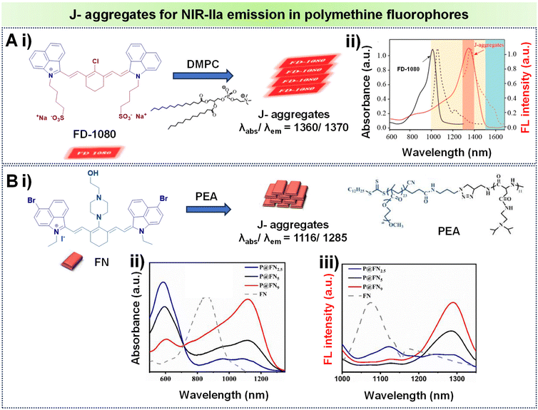 | ||
| Fig. 9 (A) (i) Formation of J-aggregates using the polymethine fluorophore FD1080 with DMPC; (ii) absorption spectra of the monomer and J-aggregates of FD-1080, illustrating absorption and emission with solid and dashed lines respectively. (B) (i) Formation of J-aggregates using the polymethine fluorophore FN with PEA; (ii) absorption spectra of the corresponding J-aggregates of FN at various molar ratios of PEA/FN; (iii) FN and its J-aggregates showing emission spectra at different PEA/FN molar ratios. Adapted with permission from ref. 84 and 85 from American Chemical Society, copyright © 2019 and Elsevier, copyright © 2022 respectively. | ||
3. Molecular design of organic fluorophores to enhance NIR-IIa brightness
Fluorescence imaging in the NIR-IIa region offers advantages such as reduced tissue scattering and diminished autofluorescence. Consequently, the role of probe brightness becomes pivotal in enhancing the signal-to-background ratio for fluorescence-related bio-applications. A key consideration for an optimal fluorophore lies in its ability to exhibit robust absorption and emission characteristics upon exposure to light. In this context, both D–A–D and polymethine fluorophores share a common feature—an extensively bulky conjugated system, accompanied by a narrow HOMO/LUMO energy gap. Unfortunately, this characteristic often results in a low QY. The fluorescence QY of NIR-II fluorophores is typically low because of limitations imposed by the energy gap law and the significant quenching behavior caused by aggregation due to highly conjugated structures, known as aggregation-caused quenching (ACQ) behavior.109 Despite this limitation, the design of NIR-IIa organic probes requires a broader perspective beyond wavelength considerations alone. Fluorescence brightness emerges as a more critical factor for bioimaging. Achieving optimal fluorescence brightness in fluorophores is a nuanced challenge influenced by two important factors: the molar extinction coefficient ε and fluorescence QY. Fluorescence brightness is not solely contingent on either the fluorescence QY or ε; rather, it is an outcome determined by the product of both factors. Hence, these parameters are intricately linked, creating a delicate balance in their optimization. Notably, the quest for a higher QY can be counteracted by a decrease in ε. This makes it challenging to boost both features at the same time.78 Until now, scientists have devised diverse approaches to address the challenge of enhancing the brightness of D–A–D and polymethine-based fluorophores. This involves implementing chemical modifications to the molecular backbones of the fluorophores, which are discussed elaborately in subsequent sections.3.1. Chemical modification of D–A–D based fluorophores to improve brightness
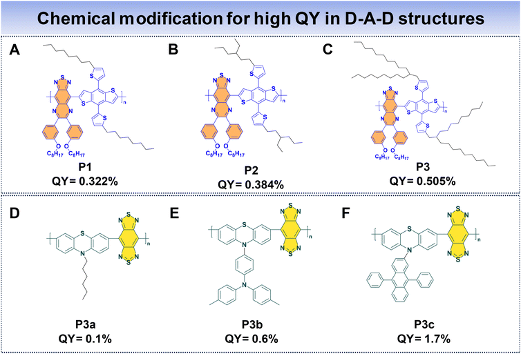
In the case of D–A–D fluorophores, researchers have identified that incorporating hydrophobic donors, incorporating long alkyl chains to donor units, or introducing shielding units to the molecular backbone prove to be an effective strategy to reduce intermolecular π–π stacking, hence reducing the ACQ that helps to suppress non-radiative decay processes, ultimately enhancing fluorescence properties.69 Additionally, the integration of AIE moieties has proved to be a successful approach for achieving high QYs for D–A–D fluorophores.33 Furthermore, introducing alternating planar and twisted molecular structures into fluorophore design has demonstrated the ability to yield high QYs and high ε.110Fan et al. introduced three distinct polymer backbones with a D–A–D structure, where each of them featured varying bulky side units. These polymers include thiadiazoloquinoxaline (TQL) and BDT as the acceptor and donor units. The donor unit is modified with different alkyl side chains to enhance the QY of the Pdots. This led to the development of P1, P2, and P3, corresponding to the introduction of linear, short, and bulky-branched side chains, respectively, as shown in Fig. 10A–C.88 To understand the structural differences, density-functional theory (DFT) was used. It showed that P3, with bulky branched side units, had the largest angle between the BDT donor and TQL acceptor units. This observation indicates a more pronounced distortion in the polymer backbone compared to P2 and P1. Consequently, P3 showcased a notable anti-ACQ effect, contributing to a higher QY. The fluorescence QYs were determined to be 0.322% for P1, 0.384% for P2, and 0.505% for P3, highlighting the impact of different side units that affected the optical characteristics of these polymers.
Wu's group utilized phenothiazine as the donor, driven by the exceptional electron-donating capabilities of sulfur and nitrogen atoms within phenothiazine. The incorporation of various side groups onto phenothiazine units imparts a nonplanar structure, effectively impeding π–π molecular stacking. To enhance the polymer's properties, they incorporated a robust acceptor, benzobisthiadiazole (BBT), resulting in the formation of three conjugated polymers (P3a, P3b, and P3c) (Fig. 10D and E) with NIR-IIa emission.48 They introduce AIE and anti-ACQ characteristics within a single molecular entity. The AIE characteristics originate from the phenothiazine donor, limiting non-radiative decay pathways in the aggregated state. Concurrently, the introduction of the anti-ACQ feature through side group modifications of phenothiazine experiences steric hindrance due to the presence of bulky side substituents, which in turn weakens π–π stacking. Among these polymers, P3c Pdots stand out, due to the bulky structure of diphenylanthracene, which ameliorates the anti-ACQ effect. Consequently, the QYs for P3a, P3b, and P3c Pdots were measured to be 0.1%, 0.6%, and 1.7%, respectively. Notably, P3c Pdots exhibit a fluorescence brightness roughly 21 times greater than that of P3a Pdots, highlighting the significant impact of side group modifications on the optical performance of these polymers.
As previously discussed, a fluorophore's brightness relies on both the QY and ε collectively. Fan's research group introduced an innovative approach to significantly augment the NIR-IIa fluorophores’ brightness by combining two distinct properties: (1) structural planarization to enhance ε and (2) a twisting configuration to boost QY within a single fluorophore. In this work, alkyl thiophenes and BBT functioned as the donor and acceptor units. Three molecules were meticulously designed, namely, B2T, B2TA, and BETA (Fig. 11A–C).83 The approach involved incorporating three thiophene units for B2T and introducing a nonconjugated alkyl side chain into the terminal thiophene of B2T to create B2TA. DFT calculations unveiled that the addition of a terminal nonconjugated alkyl unit resulted in a more planar structure for B2TA compared to B2T. Consequently, B2TA exhibited a higher absorption coefficient (ε) of 7.38 × 10³ M−1 cm−1 with a QY of 0.016%, while B2T displayed a lower ε of 3.18 × 10³ M−1 cm−1 with a QY of 0.013%. To achieve a strong absorption while preserving the fluorophore's high QY, a bulky planar 3,4-ethoxylenedioxythiophene (EDOT) unit is introduced by replacing a thiophene unit near the terminus of B2T, resulting in BETA. This led to enhanced planarity, displaying an increased ε of 11.3 × 10³ M−1 cm−1 with a QY of 0.019%, surpassing both B2T and B2TA. DFT calculations revealed that the terminal alkyl chain and bulky EDOT replacement contributed to increased molecular planarity for the fluorophore. In their research, Cai et al. introduced two fluorophores, T-BBT and BT-BBT (Fig. 11D and E), characterized by a structurally rigid and planar conformation.80 These fluorophore molecules feature BBT as the acceptor core, with the donor unit comprising thiophene and triphenylamine fused with cyclopenta-1,3-diene. Both T-BBT and BT-BBT have conjugated backbones that adopt a completely coplanar structure, as revealed by DFT calculations. This structural rigidity reduces non-radiative decay pathways related to electronic vibration coupling. This conformational planarization resulted in notably high ε values for both T-BBT and BT-BBT of 43.9 × 10³ M−1 cm−1 and 45.5 × 10³ M−1 cm−1, respectively. Simultaneously, the structural rigidity contributed to a high QY of 3.6% for T-BBT and an even more substantial QY of 13.5% for BT-BBT. The study underscores how the strategic design of fluorophores with rigid, planar conformations can effectively enhance both their absorption properties and fluorescence efficiency. By employing these strategic methods, it is possible to simultaneously achieve high values of both ε and QY in the resulting fluorophores.
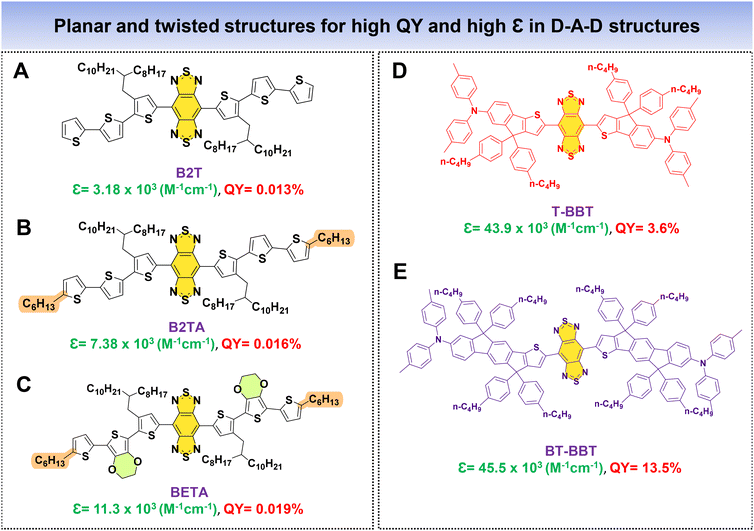 | ||
| Fig. 11 D–A–D based fluorophores (A–E) with planar and twisted molecular architectures for high QY and high ε. | ||
3.2. Improving brightness in polymethine based NIR-IIa fluorophores
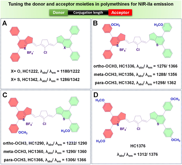
To enhance the QY of polymethine fluorophores, various strategies have been introduced.77 These include interactions with biomolecules thereby reducing nonradiative processes, imposing conformational constraint, and diminishing intersystem crossing by altering the presence of heavy atoms.111,112 Other ways to increase the brightness of polymethine dyes involve minimizing aggregation effects to maintain a molecular monomeric state, ensuring efficient absorption and emission capabilities.113,114The diminished fluorescent brightness observed in NIR-II polymethine fluorophores within biological systems is primarily attributed to ACQ, a common phenomenon. This phenomenon may arise due to the extended π-conjugation of the methine units and/or terminal heterocycle moieties, essential for achieving redshifted absorption and emission wavelengths.77,79 However, this extension unavoidably accelerates molecular self-aggregation by means of solvatochromism and π-stacking, leading to loss of symmetry, broader absorption spectra, and decreased brightness in aqueous solutions. As a practical strategy to mitigate these effects and enhance fluorophore brightness, introducing a bulky group that induces steric hindrance proves effective.77 To illustrate, Zhang's team engineered a series of heptamethine cyanine (HC) dyes, enabling precise adjustments of maximal absorption/emission wavelengths within the 1100 to 1400 nm range.77 Among the polymethine HCs shown in Fig. 8A–D, HC1342 displayed a QY of 0.015% with absorption and NIR-IIa emission peaks at 1286 nm and 1342 nm, respectively. However, when introduced into aqueous environments, HC1342 displayed reduced brightness due to the ACQ phenomenon as a result of molecular self-aggregation. To address this, one practical approach involves introducing a bulky group that induces steric hindrance. Validating this concept, HC1342 demonstrated a remarkable 13-fold increase in fluorescent brightness upon introduction into an aqueous solution, achieved through exchanging counterions for the bulky tetrakis(pentafluorophenyl) borate (F5-TPB), resulting in a QY of 0.004% and ε of 46![[thin space (1/6-em)]](https://www.rsc.org/images/entities/char_2009.gif) 560 M−1 cm−1. This contrasted with its original form paired with the smaller BF4 counter-ion, which had a QY of 0.002% and ε of 6800 M−1 cm−1, while maintaining similar absorption and emission profiles within the NIR-IIa region (Fig. 12).
560 M−1 cm−1. This contrasted with its original form paired with the smaller BF4 counter-ion, which had a QY of 0.002% and ε of 6800 M−1 cm−1, while maintaining similar absorption and emission profiles within the NIR-IIa region (Fig. 12).
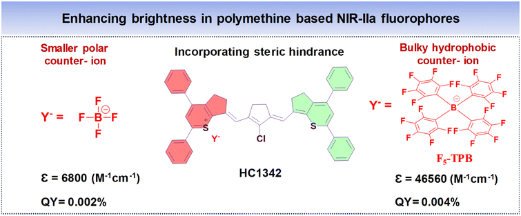 | ||
| Fig. 12 Enhancing the NIR-IIa brightness of polymethine based fluorophore HC1342 by introducing steric hindrance from smaller and bulky counter-ions. | ||
4. Applications of NIR-IIa fluorescent Pdots for deep-tissue imaging
Effective deep-tissue imaging relies mainly on both excitation and emission photons traversing through biological tissues, encountering a variety of interactions that profoundly impact imaging depth. These interactions encompass reflection occurring at the surface interface, scattering within the bio-tissues, absorption, and autofluorescence from biological species, all of which are depicted in Fig. 1.115 As we delve deeper, it becomes evident that the success of deep-tissue imaging hinges on navigating through these intricate processes. Fortunately, these factors are highly diminished as we move towards longer wavelengths. In recent years, there has been notable rise in multidisciplinary research focused on the advancement of organic fluorophores tailored for non-invasive imaging within the second near-infrared window (NIR-II, 1000–1700 nm).32,116 Consequently, the advantageous features of the NIR-IIa window, characterized by longer wavelengths (1300–1400 nm), can lead to reduced photon scattering. Additionally, there is a significant decrease in autofluorescence compared to the broader NIR-II range.35 This specific NIR-IIa wavelength range enables deep tissue imaging in living subjects, offering promising prospects for biomedical research and clinical uses. The combined benefits of reduced scattering and autofluorescence render NIR-IIa imaging highly proficient for achieving high-resolution and deep-tissue imaging.35In this scenario, various NIR-IIa emitting organic fluorophores have been developed and applied in deep-tissue fluorescence imaging. For in vivo deep tissue imaging purposes, conjugated polymers or organic dyes are embedded within an amphiphilic polymer matrix such as polyethylene glycol (PEG) segments, resulting in the formation of Pdots.117 The Pdots exhibit enhanced brightness and photostability due to the high concentration of fluorophores per particle, which are safeguarded by their surrounding polymer embedded matrix.117,118 Additionally, the presence of PEG segments on the Pdots serves to minimize nonspecific adsorption on blood proteins while extending the in vivo blood circulation time, thereby preventing rapid renal or hepatic clearance.15,33,119,120 When utilizing clinically approved agents like ICG121,122 and methylene blue (MB),123 extensively explored for deep tissue imaging applications, they exhibit short retention periods due to rapid clearance allowing for repeated administration. However, the scarcity of NIR-IIa emissive dyes has prevented the full exploration of the desired window for deep-tissue imaging. In this context, our attention in this section is predominantly centered on the exploration of deep-tissue imaging facilitated by NIR-IIa Pdots comprised of small molecules and semiconducting polymers. This review primarily focuses on utilizing NIR-IIa fluorescence imaging to achieve high-resolution visualization of diverse vascular components, encompassing those throughout the entire body, brain, hind limb, and abdomen, and for targeted tumor imaging, drawing upon findings from various research studies.
4.1. In vivo NIR-IIa fluorescence imaging of the vasculature system
The vascular system plays crucial roles in maintaining normal adult physiology and can worsen diseases by being involved in inflammation and aiding the growth and spread of cancer.124 It responds to various stimuli such as vascular endothelial growth factor A (VEGFA) by undergoing alterations in diameter, permeability, and blood flow.125 In this context, NIR-IIa fluorescence imaging can visualize blood vessels with exceptional contrast and resolution, enabling the observation of minute capillaries and the identification of subtle alterations in vascular structure. Moreover, it facilitates the real-time monitoring of blood flow and perfusion, thereby serving as a valuable tool for investigating both normal vascular physiology and pathological conditions.126,127 The SBR holds significant importance in vascular imaging as it directly impacts the quality and precision of acquired images. In the context of NIR fluorescence imaging, longer wavelengths in the NIR-II region can contribute to a higher SBR compared to the blurry NIR-I region. This improved SBR in the NIR-II region enables higher spatial resolution, deeper tissue penetration, and enhanced contrast, all essential for identifying deep lesions with high contrast.128 The newly introduced NIR-IIa window fluorophores have garnered significant interest for their potential in non-invasive in vivo imaging at longer wavelengths, attributed to their superior resolution and SBR.129,130 For example, our research group developed Pttc-SeBTa-NIR1125 Pdots and Pttc-SeBTa-NIR1380 Pdots for NIR-IIa vascular imaging in mice.49 These Pdots were synthesized by chemically bonding NIR dyes (NIR1125 and NIR1380) to a large semiconducting polymer (Pttc-SeBTa-PFCOOH), chosen for its anti-ACQ properties. This property particularly arises from the structural rigidity exhibited by the Pttc monomer, along with the steric effects offered by the SeBTa monomer. Subsequently, modifying the fluorene unit of the polymer skeleton with an azide functional group enables it to further react with the NIR dye molecules, resulting in the desired polymers. These polymers were then encapsulated into CM–PEG–DSPE to form nanoparticles (Fig. 13A and B). The Pdots demonstrated narrow absorption and emission bands ideal for NIR-IIa fluorescence imaging, which could potentially enhance penetration depth and result in a higher SBR (Fig. 13C). Compared with long-pass filters (LPFs) of different wavelengths, as shown in Fig. 13D, it is observed that longer wavelengths, despite yielding lower fluorescence emission, provide improved spatial resolution and SBR by minimizing background interference. Using a 1250 nm LPF, we observed a significantly higher SBR in vivo for Pttc-SeBTa-NIR1380 Pdots compared to Pttc-SeBTa-NIR1125 Pdots (Fig. 13E). This enhancement in SBR facilitated clearer visualization of blood vessels all over the mouse body (Fig. 13E), particularly evident in the hind limb and spinal cord regions, demonstrating the efficacy of longer wavelengths for achieving high-quality in vivo imaging with improved SBR (Fig. 13F and G). The in vivo imaging of the mouse brain vessels also demonstrated outstanding SBRs (Fig. 13H).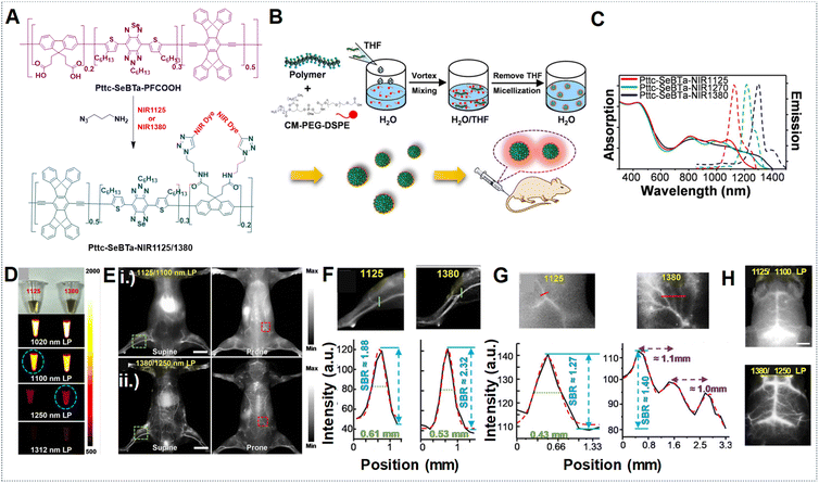 | ||
| Fig. 13 (A) Synthesis scheme for Pttc-SeBTa-NIR1125/1380 semiconducting polymers. (B) Schematic for the preparation of Pttc-SeBTa-NIR1126/1380 Pdots. (C) Absorption and emission spectra represented as solid and dashed lines, respectively, corresponding to Pttc-SeBTa-NIR1125, Pttc-SeBTa-NIR1380 and Pttc-SeBTa-NIR1270 Pdots in water shown as red, blue and green lines, respectively. (D) Images shown under ambient light (first row) of Pttc-SeBTa-NIR1125 and Pttc-SeBTa-NIR1380 Pdots (left and right) with LPFs at 1020 nm, 1100 nm, 1250 nm, and 1312 nm (bottom rows) under 808 nm laser excitation. (E) Whole-body imaging of mice post intravenous administration of Pttc-SeBTa-NIR1125/1380 Pdots imaged with different LPFs with wavelengths of 1100 nm and 1250 nm, respectively, in supine and prone positions shown in left and right images. (F) Enlarged images of mouse hind limb vasculature highlighted in the green squares of (E, i) and (E, ii) (top and bottom row, left), with green lines showing their respective cross-sectional intensity profiles in (F) for Pttc-SeBTa-NIR1125 (left)/1380 (right). (G) Expanded view of the area in the red squares marked on the spinal cord of (E, i) (top row, right) and (E, ii) (bottom row, right), with the red lines showing their respective cross-sectional intensity profiles for Pttc-SeBTa-NIR1125/1380 Pdots (right). (H) Wild-type C57BL/6 mouse brain vasculature NIR-II fluorescence imaging post-intravenous injection of Pttc-SeBTa-NIR1125/1380 Pdots displayed in top and bottom images using 1100 nm and 1250 nm LPF. Adapted with permission from ref. 49, from John Wiley and Sons, copyright © 2020. | ||
In another example, Fan's research group developed PDots based on a telechelic glycopolymer that is water soluble called TTQ-TC-PFru Pdots, which could emit in the NIR-IIa region based on the D–A–D structure (Fig. 14A).82 Upon intravenous injection of these Pdots, real-time imaging was conducted using excitation at 808 nm with varying LPFs. Higher SBRs were observed in images obtained with the 1300–1400 nm LPF compared to those obtained with the 1000–1100 nm LPF, indicating superior clarity in the images of the mouse hind limb, brain, and belly vessels (Fig. 14B, (i)–(vi)). This underscores the efficacy of longer wavelengths at improving image quality, including contrast, and penetration depth for in vivo imaging.
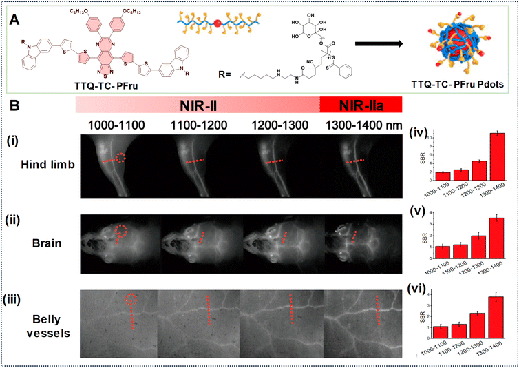 | ||
| Fig. 14 (A) Illustration depicting the formation of TTQ-TC-PFru Pdots. (B) TTQ-TC-PFru Pdots after injection into mice for NIR-IIa imaging of (i) hind limb, (ii) brain, and (iii) belly vessels using different LPFs (spanning from 1000 to 1400 nm) under 808 nm laser excitation (exposure time = 200 ms). Circles in red denote regions as a reference for background noise. (iv, v, vi) SBR values obtained from the marked regions of red dotted lines in the cross-sectional profiles of fluorescence intensity obtained with different LPFs. Reproduced with permission from ref. 82. Copyright © 2020, American Chemical Society. | ||
Elevating the SBR in fluorescence imaging has been a central area of investigation, with a focus on advancing novel fluorophores characterized by increased brightness.83 As previously discussed, Fan et al. devised highly luminous BETA nanoparticles (NPs) by incorporating planar and twisted molecular entities within the same molecular structure.83 Their findings revealed blood vessels of the brain and leg with amplified SBRs in the NIR-IIa window compared to the NIR-II region by utilizing laser excitation at 1064 nm and 808 nm, respectively as shown in Fig. 15A and D. The exceptional fluorescence brightness of BETA NPs also ensures a superior SBR when compared to its counterpart, B2TA NPs (Fig. 15B, C, E and F). Similarly, the highly bright HC1342/F5-TPB NPs, utilizing polymethine dye counter-ion pairing, produced sharp vascular images. In the mouse brain, hind limb, back, and abdomen, peak SBRs of 4.34, 4.42, 3.78, and 3.20 were attained, respectively, using a 1319 nm LPF (Fig. 15G, H, K, and L). Six tiny vessels in the back were clearly distinguished, with individual full widths at half-maximum (FWHMs) ranging from 183 to 297 μm (Fig. 15I, J, M, and N). These findings underscored the efficacy of the counter-ion-paired strategy at enhancing imaging performance through heightened brightness and elevated SBRs.
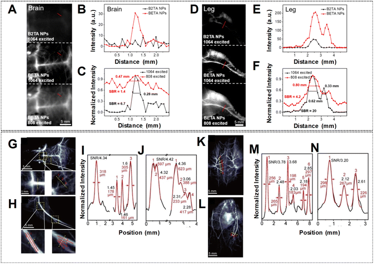 | ||
| Fig. 15 NIR-IIa fluorescence imaging of (A) brain and (D) leg vessels in the following groups: B2TA NPs under 1064 nm shown at the top with 3000 ms of exposure time, BETA NPs under 1064 nm and 808 nm laser shown in the middle and bottom with 3000 ms and 500 ms exposure times respectively. The scale bar denotes 5 mm. (B and E) Cross-sectional profiles of intensity indicated by the red lines in panels (A) and (D) (top and middle) to compare the fluorescence intensity of vessels across different groups. (C and F) Cross-sectional profile intensity indicated by the red lines in panels (A) and (D) (middle and bottom) to compare imaging quality under different laser excitation. Error bars are represented as mean ± standard deviation for n = 3. (G, K, H, L) NIR-II imaging of mouse brain (G), backside (K), hind limb (H), and abdomen (L) vasculature following injection with HC1342/F5-TPB. (I, M, J, N) Cross-sectional profiles of fluorescence intensity and Gaussian fits (black and red lines, respectively) along the yellow dashed lines in (G), (K), (H), and (L), respectively. Reproduced with permission from ref. 62 and 83, from John Wiley and Sons, Copyright © 2022. | ||
However, the limited duration of blood circulation poses challenges for the continuous monitoring of dynamic physical processes.131 Addressing this concern, Zhang's team modified the surfaces of P3a and P3c Pdots with PS–PEG to prolong the blood circulation time.48 Employing PEGylated Pdots, the mouse body was subjected to NIR-IIa imaging (Fig. 16A). Remarkably, images acquired with P3a Pdots are nearly undetectable, whereas P3c Pdots, with both AIE and anti-ACQ effects, exhibit a high SBR (Fig. 16B–D). PEGylated P3c Pdots were subsequently utilized for NIR-IIa imaging of the cerebral vasculature of the mouse. Using a LPF with a wavelength of 1319 nm (NIR-IIa) for fluorescence imaging resulted in notably sharper images with a higher SBR value than those obtained with a NIR-II LPF with a wavelength of 1250 nm (Fig. 16E–G). The high SBR remained relatively stable over 180 min due to the extended circulation half-life (approximately 6.6 h) of the PEGylated Pdots. In contrast, ICG is a small molecule dye typically cleared within about 5 min, resulting in a very brief imaging window.132
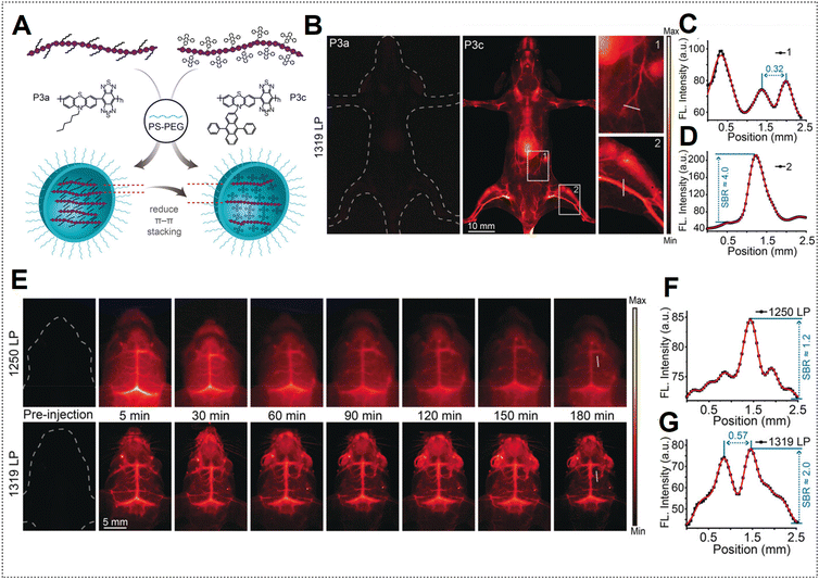 | ||
| Fig. 16 (A) Depiction of PEGylated P3a and P3c Pdot formation. (B) NIR-II fluorescence hind limb mouse vasculature images captured 5 min after injection of P3a Pdots and P3c Pdots intravenously utilizing a 1319 nm LPF under 808 nm laser excitation. (C) Cross-sectional profile intensity indicated as a white line in (B) for P3a Pdots. (D) Cross-sectional profile intensity along the white line indicated in (B) for P3c Pdots. (E) Mouse brain NIR-II fluorescence imaging at specified time intervals after injection of P3c Pdots intravenously by using a 1250 nm LPF; bottom images were obtained by using a 1319 nm LPF. (F) Cross-sectional profile intensity indicated as a white line in (E); images obtained by using a 1250 nm LPF. (G) Cross-sectional profile intensity indicated as a white line in (E); images obtained by using a 1319 nm LPF. Adapted with permission from ref. 48. John Wiley and Sons, copyright © 2020. | ||
4.2. In vivo NIR-IIa fluorescence imaging of tumors
Cancer poses a significant public health challenge, with alarming statistics indicating nearly 10 million deaths recorded in 2020. Timely detection and treatment are essential for reducing this mortality rate.133,134 In this context, harnessing the unique technical features of NIR-IIa fluorescence imaging, through the utilization of NIR-IIa Pdots, demonstrates significant promise for effectively guiding image-guided surgical tumor navigation with a high SBR.117 A robust SBR enables the reliable detection and assessment of tumors with high contrast and highly diminished background, providing valuable insights for surgical decision-making and improving cancer prognosis.135 Despite Pdots demonstrating effective resolution for imaging the vascular system as discussed in the previous section, it is crucial to note that the experimental conditions differ significantly in the case of tumor targeting from those employed in vascular imaging.It is essential to first understand the impact of delivery on the effectiveness of nanoparticles (NPs) for tumor-targeting purposes.136 Following a fundamental principle known as the “enhanced permeability and retention” (EPR) effect, nanoparticles traverse through openings between endothelial cells, known as inter-endothelial gaps.137 These gaps vary in size distribution, typically ranging from 100 to 500 nm, depending on the type and stage of the tumor, as observed in mouse models. This leads to a higher delivery efficiency and tumor accumulation in nanoparticles with hydrodynamic diameters below 100 nm compared to larger particles.138 Secondly, to prolong the circulation time of nanoparticles in vivo, researchers commonly coat the fluorophores with neutral polymers, such as PEG.126 A longer circulation time enhances the likelihood of nanoparticles accumulating in tumors. The blood half-life of nanoparticles directly correlates with the length and density of PEG ligands.126,131,139 Hence, considering the aforementioned factors, various research groups have developed nanoparticles incorporating NIR-IIa fluorophores tailored for bioimaging applications in the NIR-IIa window, ensuring efficient delivery to solid tumors in vivo.
In the work done by Ding et al., the polymethine thiopyrylium dye, known as 5H5, exhibited absorption and emission characteristics within the NIR-II window, showcasing absorption and emission peaks at 1069 nm and 1125 nm, respectively.86 Additionally, it presents an off-peak shoulder emission in the NIR-IIa window. The process of preparing 5H5 NPs involves coating them with PEG, leading to an extended blood circulation time for the PEG-modified NPs (Fig. 17A). The 5H5 NPs were injected into mice bearing U87MG tumors and a non-invasive examination of tumor vascular structures for NIR-II imaging was conducted using 808 nm and 1064 nm excitation sources. The 5H5 NPs with a hydrodynamic size smaller than 100 nm facilitates clear visualization of both tumorous microvasculature (Fig. 17B) and tumor tissues (Fig. 17C); this is attributed to tumor-selective targeted NIR-II and NIR-IIa imaging based on the EPR effect. Additionally, some fluorophores may not proficiently target tumors, necessitating the connection of a targeted molecule to enhance tumor resolution. Therefore, to enhance both tumor targetability and make the dye water soluble, the 5H5 fluorophore with a terminal alkyne group is covalently conjugated to the peptide c(RGD)fk. The highest tumor contrast, yielding a tumor tissue to non-tumor tissue (T/NT) value of 4.0, is obtained under 808 nm laser irradiation. The T/NT value increased to 6.8 under 1064 nm excitation for 8 h (Fig. 17D and E). An ex vivo biodistribution analysis conducted after 24 h revealed the accumulation of NPs in the liver and spleen when employing the 1064 nm laser, implying that the biliary system primarily facilitated clearance (Fig. 17F and G).
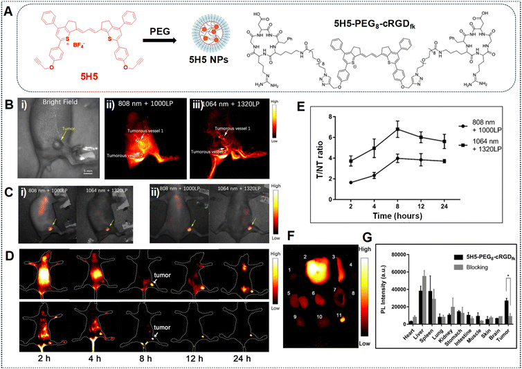 | ||
| Fig. 17 (A) Depiction of 5H5 NP formation and the structure of 5H5–PEG8–cRGDfk. (B) Tumour vasculature imaging in the NIR-II and NIR-IIa regions: (i) using 808 nm laser excitation and 1000 LPF with 100 mW cm−2 (exposure time = 100 ms), and (ii, iii) using 100 mW cm−2 1064 nm laser excitation and 1320 LPF (exposure time = 500 ms). (C) Tumor imaging after 48 h: (i) under 808 nm laser irradiation and 1000 LP LPF (exposure time = 200 ms), or (ii) under 1064 nm laser irradiation and 1320 LPF (1000 ms exposure time). (D) NIR-II and NIR-IIa imaging of U87 glioma tumors with 5H5–PEG8–cRGDfk captured under 808 nm laser irradiation and 1000 and 1320 nm LPF (exposure time = 100 ms). (E) T/NT of images obtained of the mice bearing the tumor after injection of 5H5–PEG8–cRGDfk at multiple time intervals. (F and G) Ex vivo fluorescence signals of various tissues/organs after injection of 5H5–PEG8–cRGDfk into the tumor-bearing mice at 24 h. Images were obtained under 1064 nm laser irradiation with 1320 LPF (exposure time = 500 ms). Adapted with permission from ref. 86. Copyright © 2019, American Chemical Society. | ||
In another example, Teng et al. employed a self-assembly approach involving the polymethine dye FN and the amphiphilic polypeptide PEA to create J-aggregates using P@FN9 NPs, aiming for precise NIR-IIa tumor imaging.85 Motivated by the superior NIR-IIa imaging capabilities observed in the mouse vasculature compared to NIR-II imaging, as depicted in Fig. 18A–C, the researchers conducted experiments to assess the fluorescence performance in tumor imaging. The fluorescence images of tumors in Fig. 18D show a steady rise in signal over time, attributed to the EPR effect. The T/NT fluorescence ratio demonstrated a notable increase, as shown in Fig. 18E, reaching 9.2 within 24 h post-injection, highlighting the progressive accumulation of P@FN9 NPs in the tumor. Moreover, the observation revealed a predominant localization of P@FN9 NPs in the liver and spleen, suggesting a significant contribution of the reticuloendothelial system to its metabolic pathways. The relatively intense fluorescence from the tumor suggested an increased accumulation of P@FN9 as shown in Fig. 18G and H. Additionally, the duration of the EPR effect window is assessed by monitoring the blood circulation of P@FN9. As depicted in Fig. 18F, a significant quantity of P@FN9 remained present in the bloodstream 12 h post-administration, with a notable decrease observed by 24 h, indicating the effective accumulation of P@FN9 in the tumor via the EPR effect even during the 12–24 h period following administration.
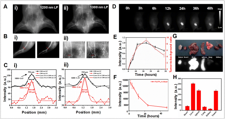 | ||
| Fig. 18 (A) Vascular imaging of mice in the NIR-II range using P@FN9 with various LPFs. (B) NIR-II vascular imaging of mouse hind limb (i) and abdominal (ii) vessels captured using P@FN9 with 1200 nm (left) and 1300 nm (right) LPFs. (C) Fluorescence intensity profiles and Gaussian fits in hind limb (i) and abdominal (ii) vessels obtained using P@FN9. (D) In vivo NIR-II imaging of P@FN9 conducted at different time intervals. (E) Fluorescence intensity profile and SBR of tumors observed at different time points (n = 5, mean ± SD). (F) Mean NIR-II fluorescence signals of P@FN9 detected in blood samples collected from mice at various time points (n = 3, mean ± SD). (G) Fluorescence images displaying organs and tumors of mice 24 h post-injection of P@FN9. (H) Fluorescence intensity measured in major organs and tumors of mice 24 h after P@FN9 injection (n = 3, mean ± SD). Adapted with permission from ref. 85. Elsevier, copyright © 2022. | ||
5. Challenges and future prospects
Despite significant advancements in NIR-IIa organic fluorophores, several challenges persist in their development. Firstly, synthesizing organic fluorophores with emission wavelengths beyond 1300 nm and high fluorescence QYs is challenging due to substantial vibrational overlap between the HOMO and LUMO, which accelerates non-radiative decay pathways, also dubbed the energy gap law.66,140 Moreover, it is important to highlight the scarcity of NIR-IIa organic fluorophores with emission maxima higher than 1300 nm as the bottleneck to their future developments in bioimaging. The structural diversity of existing organic fluorophores remains confined primarily to D–A–D, A–D–A, and polymethine architectures, thereby hindering the advancement of NIR-IIa organic fluorophores. The absence of novel molecular scaffolds presents significant challenges in the endeavour to develop effective probes beyond 1300 nm, although existing fluorophores have already been extensively studied to extend emission wavelengths. Therefore, the exploration of new molecular scaffolds or molecular engineering of existing dye molecules could potentially extend the wavelength ranges beyond 1300 nm in future research investigations.141 While advancements have been made in extending wavelength ranges, a fundamental issue arises with the emission QYs of fluorophores. Currently, most of the NIR-IIa fluorophores exhibit considerably lower QYs than NIR-I fluorophores due to factors such as a small HOMO–LUMO gap, which enables non-radiative decay more than radiative decay, and hence a low emission yield. Thus, achieving an appreciable QY relies fundamentally on the reorganization energy and vibronic coupling.142 These methods promote radiative decay pathways, thereby overcoming the energy gap law.143 Achieving this can also be entailed by specific structural adjustments to fluorophores, such as interacting with biomolecules,144 imposing conformational constraints,111 or introducing large groups that induce steric hindrance.62 For example, embedding fluorophores within proteins to form protein–fluorophore complexes could notably elevate the QYs of Pdots. This is attributed to the restricted intermolecular interactions among fluorophores, offering an effective means to enhance their fluorescent brightness.144,145 Thus, high-resolution imaging in the NIR-IIa region can be achieved by optimizing both wavelength and brightness through the implementation of molecular engineering strategies applied to the fluorophores. To date, organic fluorophores in the NIR-IIa range are classified into two main types: small molecules and semiconducting polymer dots (SPs), each offering distinct advantages and drawbacks for bioimaging purposes. Small molecule dyes, characterized by their specific structures and lower molecular weights, hold promise for clinical translation due to their potential for renal clearance.146 However, their complex structures necessitate intricate synthesis and purification procedures. On the other hand, SPs offer easier synthesis routes and purification processes, primarily utilizing well-established palladium-catalyzed Suzuki and Stille coupling reactions.38 Through careful selection of electron donor and acceptor monomers, NIR-II-absorbing SPs can be readily produced. Moreover, SPs exhibit superior photostability compared to small molecule dyes. Looking ahead, addressing the challenges of the synthetic complexity of small molecule dyes while leveraging the synthetic simplicity of SPs’ and photostability promises advancements in NIR-IIa bioimaging applications. However, similar to the method of encapsulating small molecule dyes within a polymer matrix to produce water-soluble nanoparticles, due to SPs’ large molecular weight and poor water solubility, encapsulating SPs with amphiphilic copolymers has emerged as a logical approach to create water dispersible semiconducting polymer nanoparticles (Pdots) for biological applications.57 Consequently, these probes predominantly exist on the nanoscale, proving advantageous for tumor imaging due to the EPR effect. However, SPs typically exhibit lower NIR-II fluorescence quantum yields compared to small molecule dyes, limiting their application potential. Hence, there is a pressing need to enhance the quantum yield of SPs to unlock their full capabilities in future biomedical endeavours.38Moving forward, advancements in imaging performance, particularly in terms of spatial and temporal resolution, as well as penetration depth, can be further improved by employing fluorophores capable of emitting beyond the NIR-IIa region. Hence, the advancement of organic fluorophores with extended emission wavelengths, such as those reaching into the NIR-IIb (1500–1700 nm) and NIR-III (2080–2340 nm) regions, presents a promising avenue for exploration in future research endeavors. However, current limitations in the photoresponse of conventional InGaAs detectors restrict optical imaging beyond 1700 nm. Consequently, the NIR-II window is currently delineated as not exceeding beyond 1700 nm, thereby limiting the emission capability of fluorescent dyes beyond this range.35 As we advance into the NIR-IIb/III region, the absorption of light by water becomes a critical consideration. Enhancing the image quality requires the development of NIR-IIb/III emitting dyes with high brightness to withstand attenuation by water.35 The increased water absorption around 1450 nm in the NIR-IIb region can enhance fluorescence image contrast by selectively attenuating photons with longer path lengths through tissue, including multiple scattered photons and fluorescence from deep background structures, which contribute to noise, while preserving ballistic photons that form the image.35 Some research studies have demonstrated high-contrast fluorescence imaging by harnessing the brightness of the tail emission in the NIR-IIb window, but probes with emission maxima in this window have not yet been reported.147,148 At present, the in vivo fluorescence imaging experiments beyond 1700 nm are limited due to the lack of suitable imaging probes and commercially available IR detectors. We eagerly anticipate the future emergence of novel fluorophores, such as long-wavelength-emitting Pdots, and highly efficient detection techniques, like the extended InGaAs camera.39 Despite this, there are currently no NIR-IIa/IIb/III fluorophores approved by the FDA for clinical use. Moreover, with better results in terms of spatiotemporal resolution and tissue penetration depth compared to the FDA-approved ICG-based NIR-I imaging, undoubtedly, significant efforts are required to completely introduce NIR-II imaging technology into clinical settings.39
6. Conclusion
In conclusion, the utilization of NIR-IIa fluorescent polymer dots (Pdots) for deep-tissue biomedical imaging presents a compelling avenue for advancing real-time bioimaging and facilitating future image-guided surgery. This promise is underpinned by their remarkable SBR, attributed to reduced light scattering, tissue absorption, and minimal autofluorescence. Notably, Pdots exhibit superior fluorescence brightness, exceptional biocompatibility, stability, and facile functionalization, rendering them indispensable across a spectrum of in vivo bioimaging applications. This review systematically delineates recent advancements in engineering and designing various classes of NIR-IIa organic fluorophores, with a particular emphasis on prevalent molecular frameworks such as D–A and polymethine. Key strategies for redshifting emission wavelengths while preserving high brightness encompass the incorporation of stronger donors and/or acceptors, extension of conjugation systems, formation of J-aggregates, and introduction of bulky counter-ions. However, the pervasive challenge of “quenching” presents a fundamental hurdle to achieving brighter Pdots. Effective strategies discussed include the integration of bulky shielding units, anti-aggregation caused by ACQ units, or adding AIE units into the molecular framework backbones or side chains. Besides, research findings have revealed that small molecule dyes offer promise for clinical translation due to potential renal clearance, despite complex synthesis procedures. Conversely, SPs boast easier synthesis and superior photostability but face challenges regarding quantum yield and water solubility. Encapsulating SPs with amphiphilic copolymers to form Pdots addresses solubility issues but requires improvements in quantum yield by considering effective molecular engineering strategies as discussed earlier for broader biomedical applications. Looking ahead, while organic materials have gained extensive utilization in laboratory environments, their translation into clinical applications remains constrained. Addressing extant challenges is imperative to facilitate their seamless integration into clinical practice. Therefore, there is an urgent need to develop novel organic molecules capable of circumventing these impediments, thereby unlocking their full potential in clinical settings. By overcoming these barriers, the field stands poised to realize transformative strides in deep-tissue biomedical imaging, ultimately enhancing diagnostic accuracy and therapeutic interventions.Conflicts of interest
There are no conflicts to declare.References
- B.-S. Rachel, Y. Nikolai, G. Ludmila, G. Diana, F. Alex, K. Abraham, A. Hernan, K. Zohar and I. Ora, J. Nucl. Med., 2003, 44, 1200 Search PubMed.
- A. Galperin, D. Margel, J. Baniel, G. Dank, H. Biton and S. Margel, Biomaterials, 2007, 28, 4461–4468 Search PubMed.
- U. R. Acharya, S. V. Sree, M. R. K. Mookiah, L. Saba, H. Gao, G. Mallarini and J. S. Suri, Proc. Inst. Mech. Eng., Part H, 2013, 227, 643–654 Search PubMed.
- E. Terreno, D. D. Castelli, A. Viale and S. Aime, Chem. Rev., 2010, 110, 3019–3042 Search PubMed.
- G. Rousseau, A. Blouin and J.-P. Monchalin, Opt. Express, 2008, 16, 12577–12590 Search PubMed.
- B. Dong, C. Sun and H. F. Zhang, IEEE Trans. Biomed. Eng., 2017, 64, 4–15 Search PubMed.
- J. P. Bernd, K. Armin, N. Thomas and S. Heinz-Peter, J. Nucl. Med., 2010, 51, 333 Search PubMed.
- O. M. Merkel, D. Librizzi, A. Pfestroff, T. Schurrat, M. Béhé and T. Kissel, Bioconjugate Chem., 2009, 20, 174–182 Search PubMed.
- L. B. Dale and P. W. Kathy, J. Nucl. Med., 2013, 54, 83 Search PubMed.
- A. Refaat, M. L. Yap, G. Pietersz, A. P. G. Walsh, J. Zeller, B. del Rosal, X. Wang and K. Peter, J. Nanobiotechnol., 2022, 20, 450 Search PubMed.
- P.-Y. You, F.-C. Li, M.-H. Liu and Y.-H. Chan, ACS Appl. Mater. Interfaces, 2019, 11, 9841–9849 Search PubMed.
- F. Ye, C. Wu, Y. Jin, Y.-H. Chan, X. Zhang and D. T. Chiu, J. Am. Chem. Soc., 2011, 133, 8146–8149 Search PubMed.
- L. D. Adair and E. J. New, Curr. Opin. Biotechnol., 2023, 83, 102973 Search PubMed.
- B. Huang, M. Bates and X. Zhuang, Annu. Rev. Biochem., 2009, 78, 993–1016 Search PubMed.
- W. Li, G. S. Kaminski Schierle, B. Lei, Y. Liu and C. F. Kaminski, Chem. Rev., 2022, 122, 12495–12543 Search PubMed.
- D. Bourgeois, Commun. Biol., 2023, 6, 53 Search PubMed.
- S. Shih-Po, L. Yun-Chen, L. Syue-Liang, L. Yi-Xuan, L. Min-Ying, C. Yang-Hsiang, L. Yi-Jang, Y. Muh-Hwa and C. Huihua Kenny, J. Biomed. Opt., 2023, 28, 094807 Search PubMed.
- K.-F. Hsu, S.-P. Su, H.-F. Lu, M.-H. Liu, Y. J. Chang, Y.-J. Lee, H. K. Chiang, C.-P. Hsu, C.-W. Lu and Y.-H. Chan, Chem. Sci., 2022, 13, 10074–10081 Search PubMed.
- G. M. van Dam, G. Themelis, L. M. A. Crane, N. J. Harlaar, R. G. Pleijhuis, W. Kelder, A. Sarantopoulos, J. S. de Jong, H. J. G. Arts, A. G. J. van der Zee, J. Bart, P. S. Low and V. Ntziachristos, Nat. Med., 2011, 17, 1315–1319 Search PubMed.
- A. L. Vahrmeijer, M. Hutteman, J. R. van der Vorst, C. J. H. van de Velde and J. V. Frangioni, Nat. Rev. Clin. Oncol., 2013, 10, 507–518 Search PubMed.
- Y.-C. Hsieh, K.-W. Guo, M.-W. Wang, S.-P. Su, Y.-H. Syu, C.-S. Huang and Y.-H. Chan, Ann. Surg. Oncol., 2023, 30, 8419–8427 Search PubMed.
- S. Hernot, L. van Manen, P. Debie, J. S. D. Mieog and A. L. Vahrmeijer, Lancet Oncol., 2019, 20, e354–e367 Search PubMed.
- S. L. Troyan, V. Kianzad, S. L. Gibbs-Strauss, S. Gioux, A. Matsui, R. Oketokoun, L. Ngo, A. Khamene, F. Azar and J. V. Frangioni, Ann. Surg. Oncol., 2009, 16, 2943–2952 Search PubMed.
- R. Weissleder, Nat. Biotechnol., 2001, 19, 316–317 Search PubMed.
- V. J. Pansare, S. Hejazi, W. J. Faenza and R. K. Prud'homme, Chem. Mater., 2012, 24, 812–827 Search PubMed.
- J. Li and K. Pu, Chem. Soc. Rev., 2019, 48, 38–71 Search PubMed.
- M. V. Padalkar and N. Pleshko, Analyst, 2015, 140, 2093–2100 Search PubMed.
- A. N. Bashkatov, E. A. Genina, V. I. Kochubey and V. V. Tuchin, J. Phys. D: Appl. Phys., 2005, 38, 2543 Search PubMed.
- X. Dang, N. M. Bardhan, J. Qi, L. Gu, N. A. Eze, C.-W. Lin, S. Kataria, P. T. Hammond and A. M. Belcher, Sci. Rep., 2019, 9, 3873 Search PubMed.
- R. Wang, X. Li, L. Zhou and F. Zhang, Angew. Chem., Int. Ed., 2014, 53, 12086–12090 Search PubMed.
- K. Welsher, Z. Liu, S. P. Sherlock, J. T. Robinson, Z. Chen, D. Daranciang and H. Dai, Nat. Nanotechnol., 2009, 4, 773–780 Search PubMed.
- A. M. Smith, M. C. Mancini and S. Nie, Nat. Nanotechnol., 2009, 4, 710–711 Search PubMed.
- Y.-X. Li, S.-P. Su, C.-H. Yang, M.-H. Liu, P.-H. Lo, Y.-C. Chen, C.-P. Hsu, Y.-J. Lee, H. K. Chiang and Y.-H. Chan, Adv. Healthcare Mater., 2021, 10, 2100993 Search PubMed.
- A. Sun, H. Guo, Q. Gan, L. Yang, Q. Liu and L. Xi, Opt. Express, 2020, 28, 9002–9013 Search PubMed.
- Z. Feng, T. Tang, T. Wu, X. Yu, Y. Zhang, M. Wang, J. Zheng, Y. Ying, S. Chen, J. Zhou, X. Fan, D. Zhang, S. Li, M. Zhang and J. Qian, Light: Sci. Appl., 2021, 10, 197 Search PubMed.
- J. A. Carr, M. Aellen, D. Franke, P. T. C. So, O. T. Bruns and M. G. Bawendi, Proc. Natl. Acad. Sci. U. S. A., 2018, 115, 9080–9085 Search PubMed.
- G. Hong, S. Diao, J. Chang, A. L. Antaris, C. Chen, B. Zhang, S. Zhao, D. N. Atochin, P. L. Huang, K. I. Andreasson, C. J. Kuo and H. Dai, Nat. Photonics, 2014, 8, 723–730 Search PubMed.
- Y. Liu, Y. Li, S. Koo, Y. Sun, Y. Liu, X. Liu, Y. Pan, Z. Zhang, M. Du, S. Lu, X. Qiao, J. Gao, X. Wang, Z. Deng, X. Meng, Y. Xiao, J. S. Kim and X. Hong, Chem. Rev., 2022, 122, 209–268 Search PubMed.
- C. Li, G. Chen, Y. Zhang, F. Wu and Q. Wang, J. Am. Chem. Soc., 2020, 142, 14789–14804 Search PubMed.
- J.-J. Zhang, Y. Lin, H. Zhou, H. He, J.-J. Ma, M.-Y. Luo, Z.-L. Zhang and D.-W. Pang, Adv. Healthcare Mater., 2019, 8, 1900341 Search PubMed.
- Z.-Y. Liu, A.-A. Liu, H. Fu, Q.-Y. Cheng, M.-Y. Zhang, M.-M. Pan, L.-P. Liu, M.-Y. Luo, B. Tang, W. Zhao, J. Kong, X. Shao and D.-W. Pang, J. Am. Chem. Soc., 2021, 143, 12867–12877 Search PubMed.
- O. T. Bruns, T. S. Bischof, D. K. Harris, D. Franke, Y. Shi, L. Riedemann, A. Bartelt, F. B. Jaworski, J. A. Carr, C. J. Rowlands, M. W. B. Wilson, O. Chen, H. Wei, G. W. Hwang, D. M. Montana, I. Coropceanu, O. B. Achorn, J. Kloepper, J. Heeren, P. T. C. So, D. Fukumura, K. F. Jensen, R. K. Jain and M. G. Bawendi, Nat. Biomed. Eng., 2017, 1, 0056 Search PubMed.
- Y. Zhang, H. Yang, X. An, Z. Wang, X. Yang, M. Yu, R. Zhang, Z. Sun and Q. Wang, Small, 2020, 16, 2001003 Search PubMed.
- Y. Zhong and H. Dai, Nano Res., 2020, 13, 1281–1294 Search PubMed.
- W. Shao, G. Chen, A. Kuzmin, H. L. Kutscher, A. Pliss, T. Y. Ohulchanskyy and P. N. Prasad, J. Am. Chem. Soc., 2016, 138, 16192–16195 Search PubMed.
- S. He, S. Chen, D. Li, Y. Wu, X. Zhang, J. Liu, J. Song, L. Liu, J. Qu and Z. Cheng, Nano Lett., 2019, 19, 2985–2992 Search PubMed.
- G. Qian, B. Dai, M. Luo, D. Yu, J. Zhan, Z. Zhang, D. Ma and Z. Y. Wang, Chem. Mater., 2008, 20, 6208–6216 Search PubMed.
- Z. Zhang, X. Fang, Z. Liu, H. Liu, D. Chen, S. He, J. Zheng, B. Yang, W. Qin, X. Zhang and C. Wu, Angew. Chem., Int. Ed., 2020, 59, 3691–3698 Search PubMed.
- M.-H. Liu, Z. Zhang, Y.-C. Yang and Y.-H. Chan, Angew. Chem., Int. Ed., 2021, 60, 983–989 Search PubMed.
- P. Chowdhury and Y.-H. Chan, Mol. Syst. Des. Eng., 2022, 7, 702–719 Search PubMed.
- N. Gupta, Y.-H. Chan, S. Saha and M.-H. Liu, Chem. – Asian J., 2021, 16, 175–184 Search PubMed.
- M.-H. Liu, T.-C. Chen, J. R. Vicente, C.-N. Yao, Y.-C. Yang, C.-P. Chen, P.-W. Lin, Y.-C. Ho, J. Chen, S.-Y. Lin and Y.-H. Chan, ACS Appl. Bio Mater., 2020, 3, 3846–3858 Search PubMed.
- D. M. Mayder, C. M. Tonge, G. D. Nguyen, M. V. Tran, G. Tom, G. H. Darwish, R. Gupta, K. Lix, S. Kamal, W. R. Algar, S. A. Burke and Z. M. Hudson, J. Am. Chem. Soc., 2021, 143, 16976–16992 Search PubMed.
- X. Bai, K. Wang, L. Chen, J. Zhou and J. Wang, J. Mater. Chem. B, 2022, 10, 6248–6262 Search PubMed.
- R. Gupta, W. J. Peveler, K. Lix and W. R. Algar, Anal. Chem., 2019, 91, 10955–10960 Search PubMed.
- C. Wu, T. Schneider, M. Zeigler, J. Yu, P. G. Schiro, D. R. Burnham, J. D. McNeill and D. T. Chiu, J. Am. Chem. Soc., 2010, 132, 15410–15417 Search PubMed.
- L. Feng, C. Zhu, H. Yuan, L. Liu, F. Lv and S. Wang, Chem. Soc. Rev., 2013, 42, 6620–6633 Search PubMed.
- C. Wu, S. J. Hansen, Q. Hou, J. Yu, M. Zeigler, Y. Jin, D. R. Burnham, J. D. McNeill, J. M. Olson and D. T. Chiu, Angew. Chem., Int. Ed., 2011, 50, 3430–3434 Search PubMed.
- W.-K. Tsai and Y.-H. Chan, J. Chin. Chem. Soc., 2019, 66, 9–20 Search PubMed.
- C.-S. Ke, C.-C. Fang, J.-Y. Yan, P.-J. Tseng, J. R. Pyle, C.-P. Chen, S.-Y. Lin, J. Chen, X. Zhang and Y.-H. Chan, ACS Nano, 2017, 11, 3166–3177 Search PubMed.
- M. Verma, Y.-H. Chan, S. Saha and M.-H. Liu, ACS Appl. Bio Mater., 2021, 4, 2142–2159 Search PubMed.
- Y. Yang, C. Sun, S. Wang, K. Yan, M. Zhao, B. Wu and F. Zhang, Angew. Chem., Int. Ed., 2022, 61, e202117436 Search PubMed.
- Y. Dai, Z. Sun, H. Zhao, D. Qi, X. Li, D. Gao, M. Li, Q. Fan, Q. Shen and W. Huang, Biomaterials, 2021, 275, 120935 Search PubMed.
- W. Zhang, W. Deng, H. Zhang, X. Sun, T. Huang, W. Wang, P. Sun, Q. Fan and W. Huang, Biomaterials, 2020, 243, 119934 Search PubMed.
- W. Zhang, T. Huang, J. Li, P. Sun, Y. Wang, W. Shi, W. Han, W. Wang, Q. Fan and W. Huang, ACS Appl. Mater. Interfaces, 2019, 11, 16311–16319 Search PubMed.
- R. Englman and J. Jortner, Mol. Phys., 1970, 18, 145–164 Search PubMed.
- Z. Lei and F. Zhang, Angew. Chem., Int. Ed., 2021, 60, 16294–16308 Search PubMed.
- G. H. Lee, M. G. Han, D.-S. Leem, S.-J. Lim, S. Yun, K.-H. Lee, X. Bulliard, K.-B. Park, T. Yagi, Y. S. Choi, Y. W. Jin and S. Lee, J. Phys. Chem. C, 2016, 120, 10176–10184 Search PubMed.
- Q. Yang, Z. Hu, S. Zhu, R. Ma, H. Ma, Z. Ma, H. Wan, T. Zhu, Z. Jiang, W. Liu, L. Jiao, H. Sun, Y. Liang and H. Dai, J. Am. Chem. Soc., 2018, 140, 1715–1724 Search PubMed.
- A. Ji, H. Lou, C. Qu, W. Lu, Y. Hao, J. Li, Y. Wu, T. Chang, H. Chen and Z. Cheng, Nat. Commun., 2022, 13, 3815 Search PubMed.
- W. Wu, Y. Yang, Y. Yang, Y. Yang, K. Zhang, L. Guo, H. Ge, X. Chen, J. Liu and H. Feng, Small, 2019, 15, 1805549 Search PubMed.
- F. Würthner, T. E. Kaiser and C. R. Saha-Möller, Angew. Chem., Int. Ed., 2011, 50, 3376–3410 Search PubMed.
- X.-D. Zhang, H. Wang, A. L. Antaris, L. Li, S. Diao, R. Ma, A. Nguyen, G. Hong, Z. Ma, J. Wang, S. Zhu, J. M. Castellano, T. Wyss-Coray, Y. Liang, J. Luo and H. Dai, Adv. Mater., 2016, 28, 6872–6879 Search PubMed.
- R. Tian, H. Ma, Q. Yang, H. Wan, S. Zhu, S. Chandra, H. Sun, D. O. Kiesewetter, G. Niu, Y. Liang and X. Chen, Chem. Sci., 2019, 10, 326–332 Search PubMed.
- Y. Liu, J. Liu, D. Chen, X. Wang, Z. Zhang, Y. Yang, L. Jiang, W. Qi, Z. Ye, S. He, Q. Liu, L. Xi, Y. Zou and C. Wu, Angew. Chem., Int. Ed., 2020, 59, 21049–21057 Search PubMed.
- Q. Zhao, H. Lai, H. Chen, H. Li and F. He, J. Mater. Chem. A, 2021, 9, 1119–1126 Search PubMed.
- X. Zhao, F. Zhang and Z. Lei, Chem. Sci., 2022, 13, 11280–11293 Search PubMed.
- Q. Yang, H. Ma, Y. Liang and H. Dai, Acc. Mater. Res., 2021, 2, 170–183 Search PubMed.
- M. Levitus and S. Ranjit, Q. Rev. Biophys., 2011, 44, 123–151 Search PubMed.
- L. An, L. Zheng, Z. Zhao, X. Qu, C. Liang, C. Ou, X. Mou, X. Dong and Y. Cai, J. Mater. Chem. B, 2023, 11, 8456–8463 Search PubMed.
- F. Ye, W. Huang, C. Li, G. Li, W.-C. Yang, S. H. Liu, J. Yin, Y. Sun and G.-F. Yang, Adv. Ther., 2020, 3, 2000170 Search PubMed.
- S. Chen, B. Sun, H. Miao, G. Wang, P. Sun, J. Li, W. Wang, Q. Fan and W. Huang, ACS Mater. Lett., 2020, 2, 174–183 Search PubMed.
- S. Chen, Y. Pan, K. Chen, P. Chen, Q. Shen, P. Sun, W. Hu and Q. Fan, Angew. Chem., Int. Ed., 2023, 62, e202215372 Search PubMed.
- C. Sun, B. Li, M. Zhao, S. Wang, Z. Lei, L. Lu, H. Zhang, L. Feng, C. Dou, D. Yin, H. Xu, Y. Cheng and F. Zhang, J. Am. Chem. Soc., 2019, 141, 19221–19225 Search PubMed.
- C. Teng, H. Dang, S. Zhang, Y. Xu, D. Yin and L. Yan, Acta Biomater., 2022, 154, 572–582 Search PubMed.
- B. Ding, Y. Xiao, H. Zhou, X. Zhang, C. Qu, F. Xu, Z. Deng, Z. Cheng and X. Hong, J. Med. Chem., 2019, 62, 2049–2059 Search PubMed.
- Y. C. T. Huang, P.-F. Sun, Q.-L. Fan and W. Huang, Acta Polym. Sin., 2020, 51, 346–354 Search PubMed.
- C. Yin, X. Tai, X. Li, J. Tan, C.-S. Lee, P. Sun, Q. Fan and W. Huang, Chem. Eng. J., 2022, 428, 132098 Search PubMed.
- Y. Dai, H. Zhao, K. He, W. Du, Y. Kong, Z. Wang, M. Li, Q. Shen, P. Sun and Q. Fan, Small, 2021, 17, 2102527 Search PubMed.
- X. Song, X. Lu, B. Sun, H. Zhang, P. Sun, H. Miao, Q. Fan and W. Huang, ACS Appl. Polym. Mater., 2020, 2, 4171–4179 Search PubMed.
- Y. Dai, D. Leng, Z. Guo, J. Wang, Y. Gu, Y. Peng, L. Zhu and Q. Zhao, Chem. Eng. J., 2024, 479, 147704 Search PubMed.
- C. S. Sarap, Y. Singh, J. M. Lane and N. Rai, Sci. Rep., 2023, 13, 21587 Search PubMed.
- I. Fureraj, D. S. Budkina and E. Vauthey, Phys. Chem. Chem. Phys., 2022, 24, 25979–25989 Search PubMed.
- N. I. Nijegorodov and W. S. Downey, J. Phys. Chem., 1994, 98, 5639–5643 Search PubMed.
- J. Sjöqvist, M. Linares, M. Lindgren and P. Norman, Phys. Chem. Chem. Phys., 2011, 13, 17532–17542 Search PubMed.
- J. A. Carr, D. Franke, J. R. Caram, C. F. Perkinson, M. Saif, V. Askoxylakis, M. Datta, D. Fukumura, R. K. Jain, M. G. Bawendi and O. T. Bruns, Proc. Natl. Acad. Sci. U. S. A., 2018, 115, 4465–4470 Search PubMed.
- P.-A. Bouit, C. Aronica, L. Toupet, B. Le Guennic, C. Andraud and O. Maury, J. Am. Chem. Soc., 2010, 132, 4328–4335 Search PubMed.
- M. Eskandari, J. C. Roldao, J. Cerezo, B. Milián-Medina and J. Gierschner, J. Am. Chem. Soc., 2020, 142, 2835–2843 Search PubMed.
- J. Gayton, S. A. Autry, W. Meador, S. R. Parkin, G. A. Hill Jr., N. I. Hammer and J. H. Delcamp, J. Org. Chem., 2019, 84, 687–697 Search PubMed.
- C. Sun, M. Zhao, X. Zhu, P. Pei and F. Zhang, CCS Chem., 2021, 4, 476–486 Search PubMed.
- X. Ma, Y. Huang, A. Abedi Syed Ali, H. Kim, B. Davin Tan Teck, X. Liu, W.-C. Yang, Y. Sun, H. Liu Sheng, J. Yin, J. Yoon and G.-F. Yang, CCS Chem., 2022, 4, 1961–1976 Search PubMed.
- E. E. Jelley, Nature, 1936, 138, 1009–1010 Search PubMed.
- W. Cao and E. M. Sletten, J. Am. Chem. Soc., 2018, 140, 2727–2730 Search PubMed.
- N. Dar and R. Ankari, ChemistryOpen, 2022, 11, e202200103 Search PubMed.
- J. Luo, Z. Xie, J. W. Y. Lam, L. Cheng, H. Chen, C. Qiu, H. S. Kwok, X. Zhan, Y. Liu, D. Zhu and B. Z. Tang, Chem. Commun., 2001, 1740–1741, 10.1039/B105159H.
- F. Würthner, Angew. Chem., Int. Ed., 2020, 59, 14192–14196 Search PubMed.
- J. L. Bricks, Y. L. Slominskii, I. D. Panas and A. P. Demchenko, Methods Appl. Fluoresc., 2018, 6, 012001 Search PubMed.
- C. Yang, X. Wang, M. Wang, K. Xu and C. Xu, Chem. – Eur. J., 2017, 23, 4310–4319 Search PubMed.
- L. D. Lavis and R. T. Raines, ACS Chem. Biol., 2014, 9, 855–866 Search PubMed.
- S. Liu, H. Ou, Y. Li, H. Zhang, J. Liu, X. Lu, R. T. K. Kwok, J. W. Y. Lam, D. Ding and B. Z. Tang, J. Am. Chem. Soc., 2020, 142, 15146–15156 Search PubMed.
- S. M. Usama, T. Thompson and K. Burgess, Angew. Chem., Int. Ed., 2019, 58, 8974–8976 Search PubMed.
- S. S. Matikonda, G. Hammersley, N. Kumari, L. Grabenhorst, V. Glembockyte, P. Tinnefeld, J. Ivanic, M. Levitus and M. J. Schnermann, J. Org. Chem., 2020, 85, 5907–5915 Search PubMed.
- E. D. Cosco, B. A. Arús, A. L. Spearman, T. L. Atallah, I. Lim, O. S. Leland, J. R. Caram, T. S. Bischof, O. T. Bruns and E. M. Sletten, J. Am. Chem. Soc., 2021, 143, 6836–6846 Search PubMed.
- A. Martin and P. Rivera-Fuentes, Nat. Chem., 2024, 16, 28–35 Search PubMed.
- N. B. Alexey, V. B. Kirill, N. D. Konstantin, L. C. Maria, A. G. Elina, D. G. Vadim, I. K. Vyacheslav, N. L. Ekaterina, B. P. Alexander, E. S. Marina, A. T. Polina, K. T. Daria, D. Y. Dmitry, A. Y. Dmitry, Y. Irina Yu, S. Z. Olga and V. T. Valery, J. Biomed. Opt., 2018, 23, 091416 Search PubMed.
- G. Hong, A. L. Antaris and H. Dai, Nat. Biomed. Eng., 2017, 1, 0010 Search PubMed.
- K. Li and B. Liu, Chem. Soc. Rev., 2014, 43, 6570–6597 Search PubMed.
- Z. Li, P.-Z. Liang, T.-B. Ren, L. Yuan and X.-B. Zhang, Angew. Chem., Int. Ed., 2023, 62, e202305742 Search PubMed.
- A. A. Bogdanov, R. Weissleder and T. J. Brady, Adv. Drug Delivery Rev., 1995, 16, 335–348 Search PubMed.
- R. Zhang, Z. Bi, L. Zhang, H. Yang, H. Wang, W. Zhang, Z. Qiu, C. Zhang, Y. Xiong, Y. Li, Z. Zhao and B. Z. Tang, ACS Nano, 2023, 17, 19265–19274 Search PubMed.
- J. T. Alander, I. Kaartinen, A. Laakso, T. Pätilä, T. Spillmann, V. V. Tuchin, M. Venermo and P. Välisuo, Int. J. Biomed. Imaging, 2012, 2012, 940585 Search PubMed.
- J. V. Frangioni, Curr. Opin. Chem. Biol., 2003, 7, 626–634 Search PubMed.
- M. Gupta, K. Shrivastava, V. Raghuvanshi, S. Ojha, A. Gupta and S. Sasidhar, J. Oral Maxillofac. Pathol., 2019, 23, 304 Search PubMed.
- P. Carmeliet and R. K. Jain, Nature, 2000, 407, 249–257 Search PubMed.
- D. O. Bates, D. Lodwick and B. Williams, Microcirculation, 1999, 6, 83–96 Search PubMed.
- S. Li, H. Chen, H. Liu, L. Liu, Y. Yuan, C. Mao, W. Zhang, X. Zhang, W. Guo, C.-S. Lee and X.-J. Liang, ACS Nano, 2020, 14, 13681–13690 Search PubMed.
- G. Hong, J. C. Lee, J. T. Robinson, U. Raaz, L. Xie, N. F. Huang, J. P. Cooke and H. Dai, Nat. Med., 2012, 18, 1841–1846 Search PubMed.
- Z. Feng, Y. Li, S. Chen, J. Li, T. Wu, Y. Ying, J. Zheng, Y. Zhang, J. Zhang, X. Fan, X. Yu, D. Zhang, B. Z. Tang and J. Qian, Nat. Commun., 2023, 14, 5017 Search PubMed.
- S. Yidan, Z. Xingjian and M. D. Allison, J. Biomed. Opt., 2023, 28, 094805 Search PubMed.
- W. Wang, X. He, M. Du, C. Xie, W. Zhou, W. Huang and Q. Fan, Front. Chem., 2021, 9, 769655 Search PubMed.
- B. Li, M. Zhao, L. Feng, C. Dou, S. Ding, G. Zhou, L. Lu, H. Zhang, F. Chen, X. Li, G. Li, S. Zhao, C. Jiang, Y. Wang, D. Zhao, Y. Cheng and F. Zhang, Nat. Commun., 2020, 11, 3102 Search PubMed.
- C. Li, Y. Zhang, M. Wang, Y. Zhang, G. Chen, L. Li, D. Wu and Q. Wang, Biomaterials, 2014, 35, 393–400 Search PubMed.
- R. L. Siegel, K. D. Miller, N. S. Wagle and A. Jemal, CA-Cancer J. Clin., 2023, 73, 17–48 Search PubMed.
- I. I. Wistuba, J. G. Gelovani, J. J. Jacoby, S. E. Davis and R. S. Herbst, Nat. Rev. Clin. Oncol., 2011, 8, 135–141 Search PubMed.
- P. Wang, Y. Fan, L. Lu, L. Liu, L. Fan, M. Zhao, Y. Xie, C. Xu and F. Zhang, Nat. Commun., 2018, 9, 2898 Search PubMed.
- S. Wilhelm, A. J. Tavares, Q. Dai, S. Ohta, J. Audet, H. F. Dvorak and W. C. W. Chan, Nat. Rev. Mater., 2016, 1, 16014 Search PubMed.
- R. K. Jain, Annu. Rev. Biomed. Eng., 1999, 1, 241–263 Search PubMed.
- S. Sindhwani, A. M. Syed, J. Ngai, B. R. Kingston, L. Maiorino, J. Rothschild, P. MacMillan, Y. Zhang, N. U. Rajesh, T. Hoang, J. L. Y. Wu, S. Wilhelm, A. Zilman, S. Gadde, A. Sulaiman, B. Ouyang, Z. Lin, L. Wang, M. Egeblad and W. C. W. Chan, Nat. Mater., 2020, 19, 566–575 Search PubMed.
- S. D. Perrault, C. Walkey, T. Jennings, H. C. Fischer and W. C. W. Chan, Nano Lett., 2009, 9, 1909–1915 Search PubMed.
- S. Wang, B. Li and F. Zhang, ACS Cent. Sci., 2020, 6, 1302–1316 Search PubMed.
- P. Chowdhury, Z.-Y. Lu, S.-P. Su, M.-H. Liu, C.-Y. Lin, M.-W. Wang, Y.-C. Luo, Y.-J. Lee, H. K. Chiang and Y.-H. Chan, Adv. Healthcare Mater., 2024, 2400606 Search PubMed.
- H.-M. Pan, C.-C. Wu, C.-Y. Lin, C.-S. Hsu, Y.-C. Tsai, P. Chowdhury, C.-H. Wang, K.-H. Chang, C.-H. Yang, M.-H. Liu, Y.-C. Chen, S.-P. Su, Y.-J. Lee, H. K. Chiang, Y.-H. Chan and P.-T. Chou, J. Am. Chem. Soc., 2023, 145, 516–526 Search PubMed.
- C.-C. Wu, E. Y. Li and P.-T. Chou, Chem. Sci., 2022, 13, 7181–7189 Search PubMed.
- A. L. Antaris, H. Chen, S. Diao, Z. Ma, Z. Zhang, S. Zhu, J. Wang, A. X. Lozano, Q. Fan, L. Chew, M. Zhu, K. Cheng, X. Hong, H. Dai and Z. Cheng, Nat. Commun., 2017, 8, 15269 Search PubMed.
- C. Li and Q. Wang, ACS Nano, 2018, 12, 9654–9659 Search PubMed.
- J. Huang, C. Xie, X. Zhang, Y. Jiang, J. Li, Q. Fan and K. Pu, Angew. Chem., Int. Ed., 2019, 58, 15120–15127 Search PubMed.
- S. Lu, L. Xue, M. Yang, J. Wang, Y. Li, Y. Jiang, X. Hong, M. Wu and Y. Xiao, Nano Res., 2022, 15, 9183–9191 Search PubMed.
- Y. Li, Y. Liu, Q. Li, X. Zeng, T. Tian, W. Zhou, Y. Cui, X. Wang, X. Cheng, Q. Ding, X. Wang, J. Wu, H. Deng, Y. Li, X. Meng, Z. Deng, X. Hong and Y. Xiao, Chem. Sci., 2020, 11, 2621–2626 Search PubMed.
| This journal is © The Royal Society of Chemistry 2024 |

