 Open Access Article
Hierarchical (Ni,Co)0.85Se sheets for efficient oxygen evolution reaction electrocatalysis: a combined approach of fabrication control and mechanistic understanding†
Muhammad Sohail Riaz‡
 a,
Qi Huang‡c,
Jingjing Duan
 c,
Sheng Chen
 *c,
Fuqiang Huang*b and
Pau Farras
 *a
*a
aSchool of Biological and Chemical Sciences, Energy Research Centre, Ryan Institute, University of Galway, H91 CF50 Galway, Ireland. E-mail: pau.farras@universityofgalway.ie
bState Key Lab of Metal Matrix Composites, School of Materials Science and Engineering, Shanghai Jiao Tong University, Shanghai 200240, China. E-mail: huangfq@sjtu.edu.cn
cKey Laboratory for Soft Chemistry and Functional Materials (Ministry of Education), School of Chemical Engineering, School of Energy and Power Engineering, Nanjing University of Science and Technology, Nanjing, 210094, China. E-mail: sheng.chen@njust.edu.cn
First published on 25th September 2024
Abstract
We present a fabrication process for hierarchical (Ni,Co)0.85Se sheets, achieving efficient oxygen evolution reaction (OER) activity with a 10 mA cm−2 current density at an overpotential of 290 mV. Porous architecture and doping improve kinetics, supported by DFT calculations. This approach offers insights into designing stable, high-performance OER catalysts.
Green hydrogen is considered the most environmentally friendly alternative to conventional fossil fuels as a zero-carbon fuel and energy vector.1 However, hydrogen production is still predominantly achieved through steam reforming of natural gas. This mature technology keeps prices low in the reasonably small current hydrogen market but adds a significant carbon footprint.2 Researchers predict that electrochemical water electrolysis powered by renewable energy sources will soon be the ideal technology for producing clean hydrogen.3 However, reducing costs is necessary to enhance its market competitiveness. The efficiency of this process heavily depends on the performance of oxygen evolution reaction (OER) catalysts at the anode, which face challenges due to the slow four-electron transfer reaction.4 These catalysts depend on costly noble metals, such as IrO2 or RuO2, significantly contributing to their overall cost.5 Consequently, researchers worldwide are working to develop effective, earth-abundant, robust, and scalable catalysts.6–8 Due to their low cost and abundance, efforts to replace precious metal catalysts in electrocatalysis have focused on first-row transition metals.9–11 Our bimetallic (Ni,Co)0.85Se catalyst surpasses Co0.85Se and RuO2 in alkaline media, owing to its unique morphology, metallic nature, and porous, layered structure that enhances charge transfer and provides easier access to active sites. DFT calculations show that Ni doping optimises electronic structure, improving OER kinetics by affecting intermediate Co-site interactions. This research underscores the value of fundamental studies for designing efficient catalysts in energy storage, conversion, and environmental applications.
We synthesized the (Ni,Co)0.85Se catalyst using a hydrothermal method (Fig. 1). Ni and Co nitrate salts, urea, and PVP (K30) were dissolved in distilled water, stirred, and autoclaved at 160 °C for 1 to 6 hours with Ni doping levels of 0%, 5%, 10%, and 15%. Products were extracted hourly and characterized by SEM and XRD (Fig. S1–S7, ESI†). XRD showed a transition from nanoneedle assemblies to uniform layered sheets after 6 hours (Fig. 1d and Fig. S6, ESI†). Final sheets were obtained using Na2SeO3 and N2H4 (Fig. 1e and Fig. S8, ESI†), and SEM confirmed a rough, porous surface. The morphology of undoped Co0.85Se is shown for comparison (Fig. S9, ESI†). The detailed formation mechanism of micro sheets and needle-like structures is given in (ESI†).
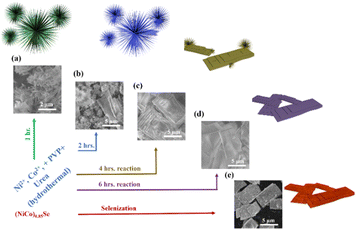 | ||
| Fig. 1 (a)–(d) Synthesis scheme and corresponding SEM images of the materials from 1 to 6 hours reaction time; (e) (Ni,Co)0.85Se porous sheets after selenisation. | ||
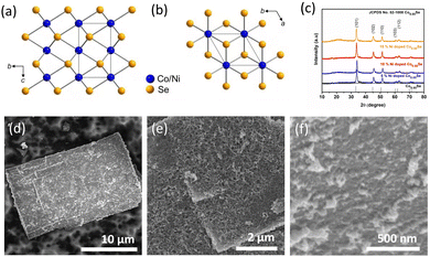
The hexagonal crystal structure of (Ni,Co)0.85Se is shown in (Fig. 2a and b). X-ray diffraction (XRD) analysis confirms the phase purity of the sample, matching the hexagonal phase of Co0.85Se with defined diffraction peaks at 2θ = 33.3°, 45.2°, and 51.2°, corresponding to the (101), (102), and (110) planes (JCPDS card no. 52-1108). Minor peak shifts indicate successful Ni doping without impurity phases in the Ni-doped samples compared to the undoped samples, confirming pure metallic phase formation. The XRD patterns for all Ni-doped and undoped samples are shown in (Fig. 2c), with sharp peaks indicating high crystallinity. Scanning electron microscopy (SEM) images reveal that 6h-NixCo2−X(CO)3(OH)2 consists of self-assembled, closely packed nanoneedles (Fig. S1, ESI†). The (Ni,Co)0.85Se sheets, obtained from the 6h-NixCo2−X(CO)3(OH)2, exhibit a rough, highly porous surface with numerous nanocrystals. These features enhance the specific surface area and facilitate rapid oxygen diffusion and mass transport, which are crucial for effective electrocatalysis. In contrast, undoped Co0.85Se forms a small size sheet after six hours (Fig. S9, ESI†).
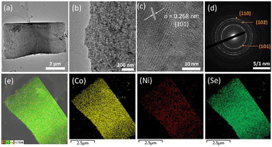
Transmission electron microscopy (TEM) further characterises the morphology of (Ni,Co)0.85Se, corroborating the SEM observations. Fig. 3a reveals that nanoparticles within the micro-sheets are interconnected, forming a well-defined layered structure without significant aggregation, as shown in (Fig. 3b). Non-uniform distribution can lead to accumulation, potentially impeding active site exposure.12 High-resolution TEM images show lattice fringes of 0.268 nm, aligning with the (101) plane of Co0.85Se as indicated by XRD. Selected area electron diffraction (SAED) patterns in (Fig. 3c) display bright rings corresponding to the (101), (102), and (110) planes, confirming the crystalline nature of (Ni,Co)0.85Se. Additionally, energy-dispersive spectroscopy (EDS) mapping in (Fig. 3e) confirms the homogeneous distribution of Ni, Co, and Se across the catalyst. TEM images for undoped Co0.85Se and 15% Ni-doped Co0.85Se are provided in (Fig. S10 and S11, ESI†) respectively.
X-ray photoelectron spectroscopy (XPS) was used to determine the valence states of the elements in the (Ni,Co)0.85Se micro-sheets. The XPS spectra for Ni 2p, Co 2p3/2, and Se 3d are shown in (Fig. 4). The Co 2p3/2 spectrum (Fig. 4a) shows binding energies at 781.1 eV and 778.5 eV, corresponding to Co3+ and Co2+, respectively.13 The Ni 2p spectrum (Fig. 4b) displays binding energies at 855.8 eV and 873.5 eV, attributed to Ni 2p3/2 and Ni 2p1/2, indicating Ni2+ presence.9 The Se 3d spectrum (Fig. 4c) reveals two types of metal–selenium bonds with peaks at 53.6 eV and 54.2 eV, suggesting the formation of Ni–Se and Co–Se bonds. A peak at 60.0 eV corresponds to Se–O,14 indicating partial contamination was removed through electrochemical preconditioning before LSV measurements in 0.1 M KOH. Also, two peaks at 58 eV and 59 eV corresponding to Co 3p3/2 can be observed, assigned to the two oxidation states as seen for Co 2p3/2.
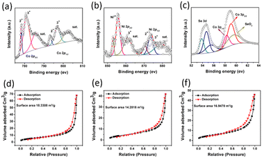 | ||
| Fig. 4 X-ray photoelectron spectroscopy for (a) Co; (b) Ni; (c) Se; BET surface area for (d) 10% Ni-doped (Ni,Co)0.85Se; (e) undoped Co0.85Se; and (f) 15% Ni-doped (Ni,Co)0.85Se. | ||
BET (Brunauer–Emmett–Teller) analysis and N2 sorption isotherms (Fig. 4d–f) were used to assess the specific surface area (SSA) and pore distribution of (Ni,Co)0.85Se sheets. The isotherms, classified as type IV with H3-type hysteresis loops, indicate mesoporous characteristics. The BET SSA values are 16.95 m2 g−1 for 5% Ni-doped sheets, 18.33 m2 g−1 for 10% Ni-doped, and 14.28 m2 g−1 for 15% Ni-doped, with pore volumes of 0.72, 0.90, and 1.98 cm3 g−1, respectively. The average pore diameter, determined via the BJH method (Fig. S12, ESI†), is 1.77 nm. As Ni content increases, higher nucleation rates lead to smaller particles and more significant surface areas (e.g. 18.33 m2 g−1 for 10% Ni-doped). However, excess Ni (15% Ni-doped) causes particle aggregation, reducing the surface area (14.28 m2 g−1).
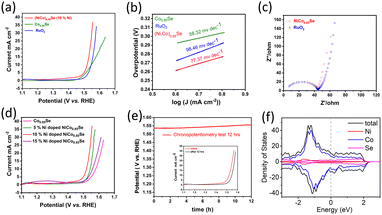
We investigated the OER performance of catalysts in a 0.1 M KOH solution using electrocatalyst-coated glassy carbon electrodes. The catalysts were electrochemically conditioned with cyclic voltammetry (CV) before evaluating water oxidation via linear sweep voltammetry (LSV). As shown in Fig. 5a, the IR-corrected LSV polarization curves, recorded at a 5 mV s−1 scan rate, reveal that both (Ni,Co)0.85Se and Co0.85Se demonstrate high OER activity with clear oxidation features. The performance comparison of the catalyst with those of the reported catalysts is given in (Table S1, ESI†). The anodic peak rise during water oxidation suggests Ni doping created additional active sites.
Electrochemical impedance spectroscopy (EIS) showed that (Ni,Co)0.85Se has lower charge transfer resistance than commercial RuO2, due to its complete electrode assembly and Ni integration into the Co0.85Se lattice.15 This lower resistance enhances electron transport at the electrolyte/electrode interface and within the electrode bulk, minimising iR losses.16 The equivalent circuit of EIS spectra and corresponding fitting data are given in (Fig. S13, ESI†). The hydrophilic nature of the (Ni,Co)0.85Se sheets ensures complete wetting of the selenide surfaces due to its porous structure,17 which improves electrolyte ion trapping and access to active sites. This hydrophilicity suggests surface hydroxylation, likely due to oxyhydroxide formation or the substitution of surface oxygen atoms with hydroxyl groups. Key metrics for evaluating OER performance include the overpotential at a current density of 10 mA cm−2, (Ni,Co)0.85Se achieves an overpotential of 290 mV at 10 mA cm−2, compared to 320 mV for Co0.85Se and RuO2. At 25 mA cm−2, (Ni,Co)0.85Se achieves an overpotential of 310 mV, outperforming RuO2 (340 mV) and Co0.85Se (390 mV). Its Tafel slope is 77.37 mV dec−1, lower than RuO2's 98.46 mV dec−1, reflecting better OER kinetics. Among Ni doping levels (5%, 10%, 15%), 10% doping yields the best performance. Impedance spectroscopy shows a charge transfer resistance of 0.45 Ω (Fig. 5c). The electrode remains stable during a 12-hour chronopotentiometry test at 10 mA cm−2, with minimal potential fluctuation and effective O2 bubble removal. Theoretical analysis (Fig. 5f) indicates a high and stable density of states (DOS) near the Fermi level, which enhances its electrical properties and performance. Post-catalytic analysis following a 12-hour chronopotentiometry test (as shown in transmission electron microscopy in (Fig. S14, ESI†) reveals that (Ni,Co)0.85Se transforms into nickel cobalt oxyhydroxides during the oxygen evolution reaction (OER)). This demonstrates that metal oxyhydroxides are the active and final forms of metal selenide pre-catalysts in OER. These findings confirm that metal selenides serve as templating precursors for forming highly active metal oxyhydroxide OER catalysts.
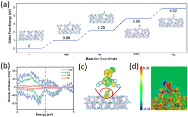
Spin-polarised density functional theory (DFT) calculations were used to investigate OER catalysis by creating a model of Co35Ni4Se46, where 10% of Co atoms were replaced with Ni. This model was sliced along the (101) crystal plane to study the adsorption and desorption of OER intermediates, including *OH, *O, *OOH, and *O2. Geometry optimisations for these intermediates (Fig. S15, ESI†) allowed the calculation of Gibbs free energies (see Computational methods). As shown in Fig. 6a, the intermediates adsorbed on Co active sites of (Ni,Co)0.85Se exhibited several uphill reaction steps at 0 V where the most endothermic step is considered as the rate-determining step (RDS).18 The corresponding Gibbs free energy change (ΔG) of RDS is a critical criterion for evaluating OER catalytic activities as the conversion of *OOH from *O for (Ni,Co)0.85Se, requiring a minimum potential of 1.41 V (or an overpotential of 0.18 V), enabling OER to occur (Fig. 6a).19,20 These results are consistent with previous examples in the literature where *OOH is usually the RDS because of its weak bonding to the surface as compared to other molecules in alkaline medium.21 The mechanism for the RDS was studied using a density of states (DOS) and charge density difference. Fig. 6b shows that the DOS profile of (Ni,Co)0.85Se spans the Fermi level without a bandgap in spin-up or spin-down channels, indicating metallic properties and excellent electronic conductivity for charge transfer during OER. This aligns well with the calculated DOS of *OH, *O, and *OOH (Fig. S16, ESI†), showing moderate interaction of these intermediates at the active site, leading to good reaction kinetics.22 A wider pseudo-gap observed for the *OOH intermediate than *O indicates a stronger bond interaction, making *OOH the RDS for OER. Charge density difference mappings for *OH (Fig. 6c), *O, and *OOH (Fig. S17, ESI†) provide further evidence for the RDS.23
The apparent charge transfer between Co and O atoms has been observed, indicating the formation of Co–O bonds inside these OER intermediates.24,25 Notably, the 2D sectional view of charge density difference (Fig. 6d and Fig. S18, ESI†) reveals more red area for *O than *OOH and others, thus confirming the difficulty of transforming from *O to *OOH.
In conclusion, metallic (Ni,Co)0.85Se porous sheets demonstrate superior performance as OER electrocatalysts compared to previous 3d-metal-based alternatives. Our study highlights that Ni doping enhances the OER activity of Co0.85Se, making (Ni,Co)0.85Se an effective and selective support for other OER catalysts through synergistic effects. The cost-effective, scalable synthesis supports our design strategy, offering a novel approach to high-performance OER catalysts, particularly heterostructures. This work advances the understanding of electrocatalyst structure–activity relationships, contributing to developing efficient catalysts for sustainable energy.
This study was supported by the Science and Technology Commission of Shanghai Municipality (23DZ1200800). M. S. R. and P. F. acknowledge the ANEMEL project (Grant Agreement No. 101071111) funded by the European Innovation Council.
Data availability
The data supporting the findings of this study are available within the article and its ESI.† Raw data will be made available in the ANEMEL project Zenodo account https://zenodo.org/communities/anemel/. The optimized atomic positions of the reaction intermediates and transition states are available from the corresponding authors on reasonable request.Conflicts of interest
There are no conflicts to declare.Notes and references
- A. Odenweller, F. Ueckerdt, G. F. Nemet, M. Jensterle and G. Luderer, Nat. Energy, 2022, 7, 854–865 CrossRef.
- R. Kumar, R. Singh and S. Dutta, Energy Fuels, 2024, 38, 2601–2629 CrossRef CAS.
- W. Tong, M. Förster, F. Dionigi, S. Dresp, R. S. Erami, P. Strasser, A. J. Cowan and P. Farràs, Nat. Energy, 2021, 6, 935 CrossRef.
- N. Han, W. Zhang, W. Guo, H. Pan, B. Jiang, L. Xing, H. Tian, G. Wang, X. Zhang and J. Fransaer, Nano-Micro Lett., 2023, 15, 185 CrossRef CAS PubMed.
- N. T. T. Thao, J. U. Jang, A. K. Nayak and H. Han, Small Sci., 2024, 4, 2300109 CrossRef CAS.
- K. M. P. Wheelhouse, R. L. Webster and G. L. Beutner, Org. Process Res. Dev., 2023, 27, 1157–1159 CrossRef CAS.
- J. Xu, J. Ruan, Y. Jian, J. Lao, Z. Li, F. Xie, Y. Jin, X. Yu, M. H. Lee and Z. Wang, Small, 2024, 20, 2305905 CrossRef CAS PubMed.
- L. Mu, S. Qiu, G. Zhao, W. Liao, N. Zhao and X. Xu, J. Mater. Chem. A, 2024, 12, 1714–1724 RSC.
- S. Sanati, A. Morsali and H. Garcia, Energy Environ. Sci., 2022, 15, 3119–3151 RSC.
- Y. Tong, Q. Sun, P. Chen, L. Chen, Z. Fei and P. J. Dyson, ChemSusChem, 2020, 13, 5112–5118 CrossRef CAS PubMed.
- Y. Tong, H. Mao, P. Chen, Q. Sun, F. Yan and F. Xi, Chem. Commun., 2020, 56, 4196–4199 RSC.
- W. Chen, L. Zhang, L. Xu, Y. He, H. Pang, S. Wang and Y. Zou, Nat. Commun., 2024, 15, 2420 CrossRef CAS PubMed.
- Y. Chen, L. Wang, H. Gan, Y. Jiang, J. Feng, J. Liu and X. Shi, J. Energy Storage, 2022, 47, 103625 CrossRef.
- U. Weser, G. Sokolowski and W. Pilz, J. Electron Spectrosc. Relat. Phenom., 1977, 10, 429–439 CrossRef CAS.
- J. A. Rajesh, J. Y. Kim, S. H. Kang and K. S. Ahn, Micromachines, 2023, 14, 1905 CrossRef PubMed.
- X. Leng, L. Zhao, W. Shi, J. Lian and X. Zhang, J. Phys. Chem. C, 2024, 128, 9422–9434 CrossRef CAS.
- C. Xia, Q. Jiang, C. Zhao, M. N. Hedhili and H. N. Alshareef, Adv. Mater., 2015, 28, 77–85 CrossRef PubMed.
- J. Yang, Y. Wang, J. Yang, Y. Pang, X. Zhu, Y. Lu, Y. Wu, J. Wang, H. Chen, Z. Kou, Z. Shen, Z. Pan and J. Wang, Small, 2022, 18, 2106187 CrossRef CAS PubMed.
- J. Gu, S. Magagula, J. Zhao and Z. Chen, Small Methods, 2019, 3, 1800550 CrossRef.
- Y. Zhao, P. Zhang, Z. Yang, L. Li, J. Gao, S. Chen, T. Xie, C. Diao, S. Xi, B. Xiao, C. Hu and W. Choi, Nat. Commun., 2021, 12, 3701 CrossRef CAS PubMed.
- W. Xu, N. Apodaca, H. Wang, L. Yan, G. Chen, M. Zhou, D. Ding, P. Choudhury and H. Luo, ACS Catal., 2019, 9, 5074–5083 CrossRef CAS.
- Y. Sun, B. Xia, S. Ding, L. Yu, S. Chen and J. Duan, J. Mater. Chem. A, 2021, 9, 20040–20047 RSC.
- D. Chen, Y. Wang, D. Liu, H. Liu, C. Qian, H. He and J. Yang, Carbon Energy, 2020, 2, 443–451 CrossRef CAS.
- S. Wang, K. Uwakwe, L. Yu, J. Ye, Y. Zhu, J. Hu, R. Chen, Z. Zhang, Z. Zhou, J. Li, Z. Xie and D. Deng, Nat. Commun., 2021, 12, 7072 CrossRef CAS PubMed.
- Y. Sun, S. Ding, B. Xia, J. Duan, M. Antonietti and S. Chen, Angew. Chem., Int. Ed., 2022, 61, e202115198 CrossRef CAS PubMed.
Footnotes |
| † Electronic supplementary information (ESI) available. See DOI: https://doi.org/10.1039/d4cc04285a |
| ‡ These authors contributed equally to this work. |
| This journal is © The Royal Society of Chemistry 2024 |

