Long-term spontaneous negative aging behavior of encapsulated blue quantum dot light emitting devices: the influence of the hole transport material†
Junfei
Chen
 *ade,
Atefeh
Ghorbani
a,
Fatemeh
Samaeifar
a,
Peter
Chun
b,
Quan
Lyu
c,
Giovanni
Cotella
c,
Dandan
Song
 de,
Zheng
Xu
de and
Hany
Aziz
a
aDepartment of Electrical and Computer Engineering and Waterloo Institute for Nanotechnology, University of Waterloo, 200 University Avenue West, Waterloo, Ontario N2L 3G1, Canada. E-mail: j2275che@uwaterloo.ca
bOttawa IC Laboratory, Huawei Canada, 19 Allstate Parkway, Markham, ON L3R 5B4, Canada
cIpswich Research Centre, Huawei Technologies Research & Development (UK) Ltd., Phoenix House (B55), Adastral Park, Ipswich IP5 3RE, UK
dKey Laboratory of Luminescence and Optical Information, Beijing Jiaotong University, Ministry of Education, Beijing 100044, China
eInstitute of Optoelectronics Technology, Beijing Jiaotong University, Beijing 100044, China
First published on 21st September 2023
Abstract
Encapsulated quantum dot light emitting devices (QLEDs) commonly exhibit a positive aging behavior, i.e., a spontaneous gradual improvement in their efficiency and performance during the first 10's of hours after encapsulation. In the long term, however, the trend reverses and the devices exhibit a spontaneous gradual deterioration in efficiency, a behavior referred to as negative aging. The root causes of this negative aging – which occurs without any electrical bias and therefore seriously limits the shelf life of QLEDs – remain unclear. Here, we carried out an in-depth analysis of the root causes behind the long-term spontaneous negative aging of encapsulated blue QLEDs. It is revealed that the long-term spontaneous negative aging is mainly due to the degradation of poly[(9,9-dioctylfluorenyl-2,7-diyl)-alt-(4,4′-(N-(4-butylphenyl))-diphenylamine)] (TFB), the most commonly used hole transport layer (HTL) material. Replacing TFB with 9,9-bis[4-[(4-ethenylphenyl)methoxy]phenyl]-N2,N7-di-1-naphthalenyl-N2,N7-diphenyl-9H-fluorene-2,7-diamine (VB-FNPD), a material that forms a cross-linked polymer, allows for preventing this negative aging behavior and maintaining the efficiency of the devices for over two months. This work provides design principles to realize long shelf-life QLEDs, and presents a new starting point for both fundamental studies and technological innovation.
Introduction
Since their first demonstration in 1994,1 quantum dot light emitting devices (QLEDs) have attracted immense interest from the research commonly due to their tremendous potential for flat panel display applications. This potential stems from their ability to offer a unique set of attractive features that include a wide color gamut range, high efficiency, low power consumption, amenability to low-cost fabrication processes, and compatibility with large-size and flexible substrates.2–11 After decades of development, the external quantum efficiency (EQE) of colloidal CdSe-based QLEDs has witnessed significant improvements from an initial 0.1% to over 20%2–11 reaching the theoretical limit possible for planar devices.12,13 In addition, the unique sub-bandgap turn-on phenomenon offers the possibility for the development of up-conversion devices with power conversion efficiency exceeding 100%.10 Besides the high efficiencies and low power consumption, a stable EL performance over time is also important for display applications. Electrical bias can drive various changes in the materials resulting in a deterioration in the EL performance of QLEDs and limiting their operational lifetime. Changes can also occur spontaneously (i.e. without electrical bias) limiting their shelf-life. Studies reveal that, in addition to the QDs themselves, the properties of the other functional layers (i.e. the charge injection and transport layers) and interlayer interfaces play critical roles in both stability behaviors.14,15 Although of critical importance for commercialization, the issue of the shelf stability of QLEDs has received very little attention from the scientific community.In general, because of the sensitivity of the QDs, metal oxide nanoparticle electron transport materials, and the organic hole transport materials to the ambient, QLEDs are usually encapsulated using a glass cover that is sealed to the substrate using ultraviolet (UV)-curable resin to protect them from the ambient. In the case of blue QLEDs in particular, such encapsulation is also essential for obtaining high efficiency.13,16 Surprisingly, a so-called positive aging behavior, i.e., a spontaneous gradual improvement in device performance including its efficiency, is often observed in encapsulated QLEDs in the short term (i.e. during the first 10's hours after encapsulation).13,16–20 In the long term, however, the trend reverses and the devices exhibit a spontaneous gradual deterioration in efficiency that occurs even without any electric bias, often referred to as spontaneous negative aging.16,17,19,21 The underlying mechanism for this spontaneous negative aging behavior in encapsulated QLEDs remains unclear. Therefore, the shelf life of QLEDs, even state-of-the-art ones, continues to be generally limited, which is an issue that urgently calls for solutions.
In this work, we carry out mechanistic in-depth studies to elucidate the factors behind this long-term spontaneous negative aging behavior in encapsulated blue QLEDs. The electron transport and hole transport parts of the device are studied separately. Analysis of current changes shows that this behavior is primarily associated with degradation in poly[(9,9-dioctylfluorenyl-2,7-diyl)-alt-(4,4′-(N-(4-butylphenyl))-diphenylamine)] (TFB), the commonly used hole transport layer (HTL). Replacing TFB with a cross-linkable material 9,9-bis[4-[(4-ethenylphenyl)methoxy] phenyl]-N2,N7-di-1-naphthalenyl-N2,N7-diphenyl-9H-fluorene-2,7-diamine (VB-FNPD) allows for taking advantage of the benefits of the initial positive aging behavior yet prevents the subsequent negative aging behavior. With this stable HTL, the shelf life of the QLEDs is significantly enhanced, maintaining their efficiency for 2 months under storage conditions. Our work provides an in-depth and systematic understanding of the mechanism of negative aging and offers a practical method for realizing more robust QLEDs.
Results and discussion
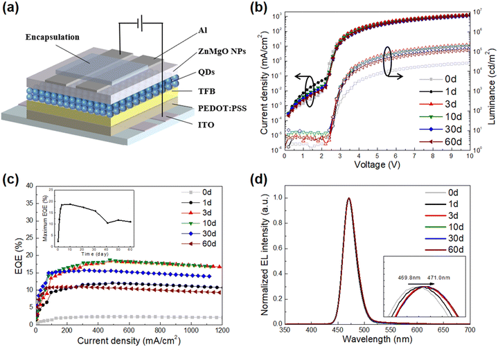
Upright blue QLEDs with the structure of ITO (100 nm)/PEDOT: PSS (45 nm)/HTL/B-QDs (20 nm)/ZnMgO (60 nm)/Al (100 nm) were fabricated and characterized. In these devices, the ITO and Al serve as hole and electron-injecting contacts respectively whereas the PEDOT: PSS and ZnMgO serve as a hole injection layer and an electron transport layer (ETL) respectively. For HTL, three commonly used hole transport materials are selected; poly-TPD, TFB and PVK. The materials were coated from solutions with different concentrations to produce HTLs of different thicknesses in order to obtain the best device performance. All layers except for the cathode Al were deposited by sequential spin-coating on the ITO. After fabrication, the QLEDs were encapsulated with UV-curable resin and then stored in a nitrogen-filled glovebox. Fig. S2 (ESI†) shows the density–voltage–luminance (J–V–L) and EQE characteristics of these devices. It can be seen that the EQE of the blue QLEDs does not change appreciably with the HTL material concentration. The best EQEs of devices with poly-TPD and PVK as HTLs are 1.46% and 1.71% respectively. With TFB – in contrast – the EQE is significantly higher, reaching 7.71% for a concentration of 8 mg ml−1. The higher EQE can be attributed to the higher hole mobility of TFB and its better matching energy levels. Therefore we use the TFB-based devices for the purpose of studying the shelf stability of the QLEDs. A schematic diagram of the device structure is shown in Fig. 1a. To evaluate the shelf stability of the devices, the devices were tested immediately after encapsulation (0 d) and after storage for 1, 3, 10, 30, and 60 days. Fig. 1b shows the J–V–L characteristics of these devices at the given times. The curves are from a typical device out of a group of 3 devices of the same structure. It is clear that the performance changes of the QLEDs during storage exhibits 2 behaviors: (1) a positive aging behavior that appears in the first 10 days in the form of a significant spontaneous increase in the luminance at any given voltage, accompanied by a decrease in the leakage current, and (2) a negative aging behavior that occurs in the long term and appears in the form of a spontaneous decrease in the luminance and current density. The performance improvement of the devices during positive aging can be attributed to the increase in electron transport,13,16–19,21 so in this work, we only focus on investigating the spontaneous negative aging behavior. Not surprisingly, the changes in current density and luminance lead to changes in devices’ EQE. As shown in Fig. 1c, during the positive aging stage (i.e. in the first 10 days), the EQEmax of the devices increases from 2.38% to 18.74%. It, however, later decreases, dropping to 11.02% after 60 days. Fig. 1d shows the electroluminescence (EL) spectra of the devices. The spectra show a slight red shift during the positive aging stage. In contrast, during the negative aging stage, the EL spectrum does not exhibit any detectable shifts, indicating that the causes of positive and negative aging may be different. The electrical performance characteristics of devices are summarized in Table 1. The presented data represent the averages and standard deviations from measurements on 15 devices of the same structure. | ||
| Fig. 1 (a) Device structure, (b) J–V–L, (c) EQE–J, inset is the EQEmax changes over time. (d) EL spectra of blue QLEDs with encapsulation stored for different days in a nitrogen-filled glovebox. | ||
| Devices | EL peaka (nm) | FWHMb (nm) | V (V) | L (cd m−2) | CEmaxe (cd A−1) | EQEmaxf (%) |
|---|---|---|---|---|---|---|
| a Electroluminescence peak at 20 mA cm−2. b Full width at half maximum of EL spectra. c Measured voltage under the driving current density of 20 mA cm−2. d Luminance at 10 V. e Maximum current efficiency. f Maximum external quantum efficiency. | ||||||
| 0 d | 469.8 | 27.8 | 3.03 ± 0.04 | 26![[thin space (1/6-em)]](https://www.rsc.org/images/entities/char_2009.gif) 475 ± 4564 475 ± 4564 |
2.32 ± 0.52 | 2.38 ± 0.54 |
| 1 d | 470.6 | 28.2 | 3.00 ± 0.02 | 140![[thin space (1/6-em)]](https://www.rsc.org/images/entities/char_2009.gif) 768 ± 12 768 ± 12![[thin space (1/6-em)]](https://www.rsc.org/images/entities/char_2009.gif) 672 672 |
12.19 ± 0.64 | 12.10 ± 0.53 |
| 3 d | 471.4 | 28.8 | 2.96 ± 0.04 | 22![[thin space (1/6-em)]](https://www.rsc.org/images/entities/char_2009.gif) 2146 ± 10 2146 ± 10![[thin space (1/6-em)]](https://www.rsc.org/images/entities/char_2009.gif) 120 120 |
19.19 ± 1.62 | 18.48 ± 1.48 |
| 10 d | 471.4 | 28.9 | 2.98 ± 0.05 | 197![[thin space (1/6-em)]](https://www.rsc.org/images/entities/char_2009.gif) 328 ± 21 328 ± 21![[thin space (1/6-em)]](https://www.rsc.org/images/entities/char_2009.gif) 146 146 |
19.50 ± 2.44 | 18.74 ± 1.28 |
| 30 d | 471.4 | 28.9 | 3.16 ± 0.09 | 165![[thin space (1/6-em)]](https://www.rsc.org/images/entities/char_2009.gif) 335 ± 26 335 ± 26![[thin space (1/6-em)]](https://www.rsc.org/images/entities/char_2009.gif) 248 248 |
16.67 ± 2.42 | 15.78 ± 1.53 |
| 60 d | 471.0 | 28.9 | 3.22 ± 0.04 | 118![[thin space (1/6-em)]](https://www.rsc.org/images/entities/char_2009.gif) 749 ± 13 749 ± 13![[thin space (1/6-em)]](https://www.rsc.org/images/entities/char_2009.gif) 028 028 |
11.85 ± 1.20 | 11.02 ± 0.94 |
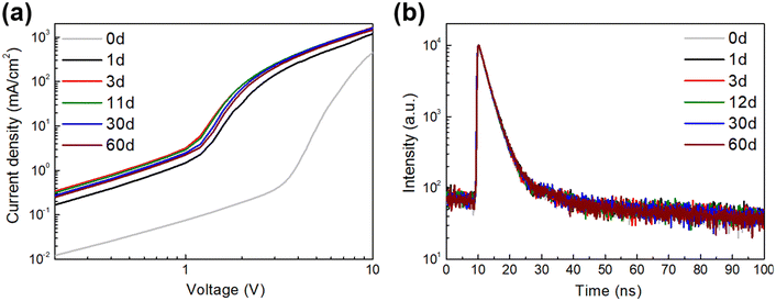
To investigate if the long-term negative aging behavior is also associated with changes in electron injection, we fabricated electron-only devices with the structure ITO/ZnO sol–gel/B-QDs/ZnMgO/Al. The devices were encapsulated and tested immediately after fabrication (0 d) and after storage in a glovebox for 1, 3, 11, 30, and 60 days. As can be seen from the J–V curve in Fig. 2a, the electron current does not change significantly after the first 3 days, indicating that the negative aging behavior is not associated with changes in electron injection or transport in the devices. The QDs exciton lifetime is also investigated. Samples with the structure of glass/B-QDs/ZnMgO/Al were fabricated and tested immediately after encapsulation (0 d) and after storage for 1, 3, 12, 30, and 60 days in a glovebox. Fig. 2b shows time-resolved photoluminescence (TRPL) decay curves collected at 460 nm under 380 nm excitation. As can be seen, the exciton lifetime of B-QDs remains unchanged over the same period. The above results show that the long-term negative aging behavior of encapsulated QLEDs is not due to changes in exciton relaxation behavior or quenching phenomena affecting the QDs.
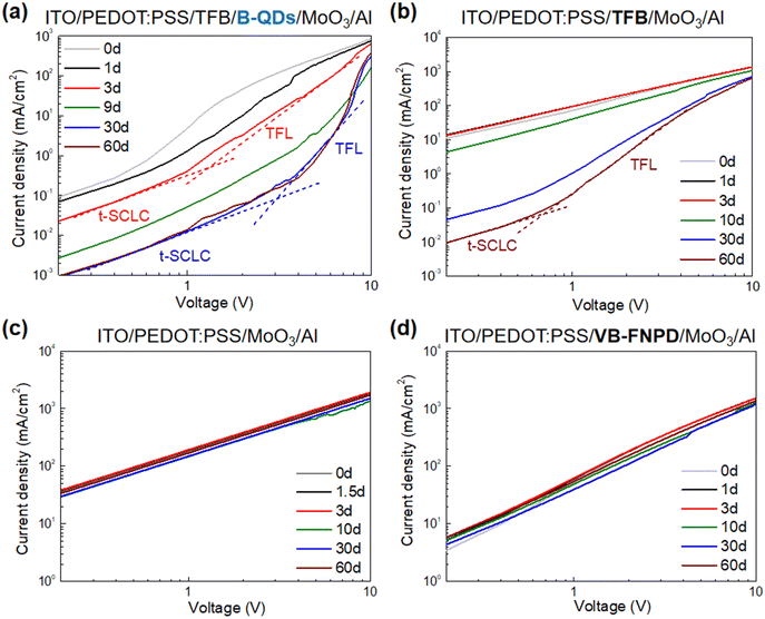
With changes in electron supply and exciton quenching dynamics ruled out, the other possible cause for the long-term negative aging is a change in the hole injection and transport to QDs. Therefore, hole-only devices (QDs-HODs) with the structure ITO/PEDOT: PSS/TFB/B-QDs/MoO3/Al were fabricated and encapsulated. The HODs were tested immediately after fabrication (0 d) and after storage in the glovebox for 1, 3, 9, 30, and 60 days. Fig. 3a shows the J–V characteristics. As can be seen, the J–V characteristics show significant changes over time in stark contrast to the J–V characteristics of the EODs presented earlier. In unipolar transport, the J–V characteristics are typically composed of 4 distinct regions with different J versus V power-law dependencies (J ∝ Vn): (1) ohmic conduction (n = 1), (2) trap-limited space charge limited conduction (t-SCLC, n = 1–2), (3) trap-filled limited (TFL) conduction (n > 2) and (4) space charge limited conduction (SCLC, n = 2).22–24 Among the four regions, ohmic conduction usually occurs only in defect-free devices and at very low voltages, and therefore is not usually observed in real devices. Both the t-SCLC and TFL regions (especially the TFL region) are significantly affected by charge traps. As shown in Fig. 3a, the current density of QDs-HODs decreases significantly and the transition from t-SCLC to TFL becomes more pronounced after 30 days, which corresponds to the time over which the negative aging behavior in the QLEDs becomes significant. The exponent value of the TFL region increases from 3.43 to 6.11, pointing to an increase in the number of deep traps, which may be caused by material degradation during long-term storage.22–24 To further identify which layer is behind the changes in the hole current, HODs in which some of the layers are removed are also fabricated and tested for comparison. At first, TFB-HODs with the structure of ITO/PEDOT: PSS/TFB/MoO3/Al (without B-QDs) were fabricated and encapsulated. As shown in Fig. 3b, the hole current still decreases significantly and the TFL region is more significant after 30 days during negative aging, indicating that the decrease in hole current is not due to QDs degradation. Next, PEDOT: PSS-HODs with the structure of ITO/PEDOT: PSS/MoO3/Al were fabricated and encapsulated. As can be seen in Fig. 3c, when only PEDOT: PSS is present in the HODs, the hole current does not change during long-term storage. From these observations, it can be concluded that the deterioration in hole conduction that occurs during negative aging is associated with the TFB layer. To verify this conclusion, a stable thermally cross-linked hole transport material, VB-FNPD is used instead of TFB as the HTL to fabricate encapsulated VB-FNPD-HODs with the structure of ITO/PEDOT: PSS/VB-FNPD/MoO3/Al. As shown in Fig. 3d, the hole current remains unchanged over the same 60 days measurement time in this case. The above results indicate that the deterioration in device performance during long-term negative aging behavior is due to degradation in TFB material in the encapsulated devices that leads to a decrease in hole transport.
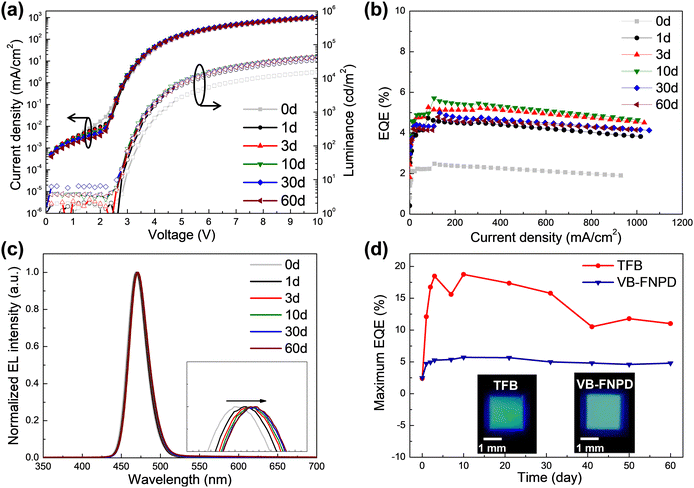
Finding that replacing TFB by VB-FNPD in HODs suppresses changes in hole currents over time, VB-FNPD is used as HTL in upright QLEDs with the same structure as before, i.e. ITO/PEDOT: PSS/VB-FNPD/B-QDs/ZnMgO/Al to further verify whether the negative aging behavior of the device is due to the HTL. After fabrication, the QLEDs were again encapsulated with UV-curable resin and then stored in a nitrogen-filled glovebox. As before, the devices were tested immediately after encapsulation (0 d) and after storage in a glove box for 1, 3, 10, 30, and 60 days. From the J–V–L in Fig. 4a, a positive aging behavior is still observed over the first 10 days in the form of a significant increase in the luminance at any given voltage, accompanied by a decrease in the leakage current. This is not surprising since the positive aging behavior is associated with changes in electron injection into the QD and therefore is not expected to change upon changing the HTL material. In contrast however, in this case, the long-term negative aging behavior is not observed, evident from the luminance and current density characteristics that remain unchanged in the long term and the little changes in the EQE and EL spectra after 60 days vs after 30 days of storage as shown in Fig. 4b and c. The spectra still show a slight red shift in the short term, which also indicates that positive aging still happens. To compare the stability of the devices, the maximum EQE versus t curves of QLEDs with TFB and VB-FNPD as HTL are shown in Fig. 4d. It can be seen that there is obvious negative aging behavior in TFB devices after 10 days, the maximum EQE gradually decreases with storage time. In contrast, with VB-FNPD as HTL, the maximum EQE of devices remains relatively unchanged even after 60 days of storage. Optical images of encapsulated B-QLEDs with TFB and VB-FNPD as HTL stored for 60 days in a nitrogen-filled glovebox are shown in insets in Fig. 4d. It can be seen that after long-term storage, the edges of the device with the TFB HTL becomes darker and the luminescence is not uniform, whereas the device with VB-FNPD as HTL remains uniform. This also proves that the TFB deteriorates in encapsulated QLEDs over time. While the underlying mechanisms involved in TFB degradation are still unclear, that the degradation seems to start from the device edges (despite being encapsulated and kept in a glovebox at all times) points to a possible reaction between the UV-curable resin byproducts that are trapped in the encapsulation enclosure and slowly diffuse through the layer edges over time, and TFB that causes its hole transport properties to deteriorate. In contrast, since the VB-FNPD devices remain uniform over the same period and do not show any similar darkening around the edges indicates that the VB-FNPD is not similarly negatively affected by the UV-curable resin or at least that the reaction kinetics are much slower. From these results, it can be concluded that the widely used TFB plays a leading role in limiting the shelf-life of encapsulated QLEDs and that replacing it with VB-FNPD significantly improves stability.
Conclusions
The origins of the long-term spontaneous negative aging behavior that occurs – without electrical bias – in encapsulated blue QLEDs and seriously limits their shelf-life is systematically investigated. Analysis of the J–V characteristics of unipolar hole-only and electron-only devices shows that the long-term spontaneous negative aging of the encapsulated device is due to TFB degradation. To fully take advantage of positive aging but prevent the subsequent negative aging behavior, a cross-linking material VB-FNPD is used instead of TFB as the hole transport layer. With the stable HTL, the encapsulated QLED exhibits a much longer shelf life, maintaining its high efficiency for over two months in storage. Our studies uncover the origin of the long-term spontaneous negative aging and provides a method to improve the shelf stability of encapsulated QLEDs, which offer a new starting point for further research to improve the stability of blue QLEDs for commercial applications.Conflicts of interest
There are no conflicts to declare.Acknowledgements
The financial support from the China Scholarship Council (CSC) and Huawei Technologies Corp. is gratefully acknowledged.References
- V. L. Colvin, M. C. Schlamp and A. P. Alivisatos, Nature, 1994, 370, 354–357 CrossRef CAS.
- S. Coe, W. K. Woo, M. Bawendi and V. Bulovic, Nature, 2002, 420, 800–803 CrossRef CAS PubMed.
- B. S. Mashford, M. Stevenson, Z. Popovic, C. Hamilton, Z. Q. Zhou, C. Breen, J. Steckel, V. Bulovic, M. Bawendi, S. Coe-Sullivan and P. T. Kazlas, Nat. Photonics, 2013, 7, 407–412 CrossRef CAS.
- X. L. Dai, Z. X. Zhang, Y. Z. Jin, Y. Niu, H. J. Cao, X. Y. Liang, L. W. Chen, J. P. Wang and X. G. Peng, Nature, 2014, 515, 96–99 CrossRef CAS PubMed.
- Y. X. Yang, Y. Zheng, W. R. Cao, A. Titov, J. Hyvonen, J. R. Manders, J. G. Xue, P. H. Holloway and L. Qian, Nat. Photonics, 2015, 9, 259–266 CrossRef CAS.
- L. S. Wang, J. Lin, Y. S. Hu, X. Y. Guo, Y. Lv, Z. B. Tang, J. L. Zhao, Y. Fan, N. Zhang, Y. J. Wang and X. Y. Liu, ACS Appl. Mater. Interfaces, 2017, 9, 38755–38760 CrossRef CAS PubMed.
- W. R. Cao, C. Y. Xiang, Y. X. Yang, Q. Chen, L. W. Chen, X. L. Yan and L. Qian, Nat. Commun., 2018, 9, 2608 CrossRef PubMed.
- H. B. Shen, Q. Gao, Y. B. Zhang, Y. Lin, Q. L. Lin, Z. H. Li, L. Chen, Z. P. Zeng, X. G. Li, Y. Jia, S. J. Wang, Z. L. Du, L. S. Li and Z. Y. Zhang, Nat. Photonics, 2019, 13, 192–197 CrossRef CAS.
- T. Kim, K. H. Kim, S. Kim, S. M. Choi, H. Jang, H. K. Seo, H. Lee, D. Y. Chung and E. Jang, Nature, 2020, 586, 385–389 CrossRef CAS PubMed.
- Q. Su and S. M. Chen, Nat. Commun., 2022, 13, 369 CrossRef CAS PubMed.
- A. Ghorbani, J. F. Chen, F. Samaeifar, M. Azadinia, P. Chun, Q. Lyu, G. Cotella and H. Aziz, J. Phys. Chem. C, 2022, 126, 18144–18151 CrossRef CAS.
- C. D. Pu, X. L. Dai, Y. F. Shu, M. Y. Zhu, Y. Z. Deng, Y. Z. Jin and X. G. Peng, Nat. Commun., 2020, 11, 937 CrossRef CAS PubMed.
- Z. N. Chen, Q. Su, Z. Y. Qin and S. M. Chen, Nano Res., 2021, 14, 320–327 CrossRef CAS.
- H. Moon, C. Lee, W. Lee, J. Kim and H. Chae, Adv. Mater., 2019, 31, 1804294 CrossRef PubMed.
- F. Z. Wang, Z. Y. Wang, X. D. Zhu, Y. M. Bai, Y. Yang, S. Q. Hu, Y. Q. Liu, B. G. You, J. Wang, Y. Li and Z. A. Tan, Small, 2021, 17, 2007363 CrossRef CAS PubMed.
- B. Y. Lin, W. C. Ding, C. H. Chen, Y. P. Kuo, P. Y. Chen, H. H. Lu, N. Tierce, C. J. Bardeen, J. H. Lee, T. L. Chiu and C. Y. Lee, Chem. Eng. J., 2021, 417, 127983 CrossRef CAS.
- K. P. Acharya, A. Titov, J. Hyvonen, C. G. Wang, J. Tokarz and P. H. Holloway, Nanoscale, 2017, 9, 14451–14457 RSC.
- Q. Su, Y. Z. Sun, H. Zhang and S. M. Chen, Adv. Sci., 2018, 5, 1800549 CrossRef PubMed.
- D. S. Chen, D. Chen, X. L. Dai, Z. X. Zhang, J. Lin, Y. Z. Deng, Y. L. Hao, C. Zhang, H. M. Zhu, F. Gao and Y. Z. Jin, Adv. Mater., 2020, 32, 2006178 CrossRef PubMed.
- W. J. Zhang, X. T. Chen, Y. H. Ma, Z. W. Xu, L. J. Wu, Y. X. Yang, S. W. Tsang and S. Chen, J. Phys. Chem. Lett., 2020, 11, 5863–5870 CrossRef CAS PubMed.
- Z. N. Chen, Z. Y. Qin, X. Y. Zhou, J. W. Long and S. M. Chen, J. Soc. Inf. Disp., 2019, 50, 656–659 Search PubMed.
- S. K. Kim, H. Yang and Y. S. Kim, J. Appl. Phys., 2019, 126, 185702 CrossRef.
- S. K. Kim and Y. S. Kim, J. Appl. Phys., 2019, 126, 035704 CrossRef.
- M. Chrzanowski, G. Zatryb, P. Sitarek and A. Podhorodecki, ACS Appl. Mater. Interfaces, 2021, 13, 20305–20312 CrossRef CAS PubMed.
Footnote |
| † Electronic supplementary information (ESI) available. See DOI: https://doi.org/10.1039/d3tc01720f |
| This journal is © The Royal Society of Chemistry 2023 |


