 Open Access Article
Creative Commons Attribution 3.0 Unported Licence
Post-imprinting modification: electrochemical and scanning electrochemical microscopy studies of a semi-covalently surface imprinted polymer†
Jakub
Kalecki
a,
Maciej
Cieplak
 a,
Zofia
Iskierko
a,
Joanna
Piechowska
a,
Zofia
Iskierko
a,
Joanna
Piechowska
 a,
Wojciech
Nogala
a,
Francis
D’Souza
a,
Wojciech
Nogala
a,
Francis
D’Souza
 b and
Piyush Sindhu
Sharma
 *a
*a
aInstitute of Physical Chemistry, Polish Academy of Sciences, Kasprzaka 44/52, 01-224 Warsaw, Poland. E-mail: psharma@ichf.edu.pl
bDepartment of Chemistry, University of North Texas, 1155 Union Circle No. 305070, Denton, TX 76203-5017, USA
First published on 25th January 2023
Abstract
Herein we described a post-imprinting modification of the imprinted molecular cavities for electrochemical sensing of a target protein. Imprinted molecular cavities were generated by following the semi-covalent surface imprinting approach. These mesoporous cavities were modified with a ferrocene ‘electrochemical’ tracer for electrochemical transduction of the target protein recognition. Electrochemical sensors prepared after post-imprinting modification showed a linear response in the concentration range of 0.5 to 50 μM. Chemosensors fabricated based on capacitive impedimetric transduction demonstrated that imprinted molecular cavities without post-imprinting modification showed better selectivity. Scanning electrochemical microscopy (SECM) was used for the surface characterization of imprinted molecular cavities modified with ferrocene electrochemical tracers. SECM analysis performed in the feedback mode monitor changes in the surface state of the ferrocene-modified polymer film. The kinetics of the mediator regeneration was almost 1.8 times higher on the non-imprinted surface versus the post-imprinting modified molecular imprinted polymer.
1. Introduction
Polymer-based synthetic receptors have been reported as alternatives to antibodies with comparable molecular recognition capabilities.1–3 Following the molecular imprinting approach to synthesize such receptors has proven to be one of the most promising strategies for antibody mimicking. This approach has been used to synthesize nanostructured polymers exhibiting antibody–antigen-like affinity for template analytes such as drugs, toxins, biomarker biomolecules, and macromolecules, including proteins and peptides.4,5Molecular imprinting describes producing molecular recognition sites in polymers by templating. It outlines polymerization initiation in the presence of the target analyte (template) and polymerizing monomers. The resulting growing polymer chain integrates the functional monomer complex with the template. Removing the template molecules from the polymer matrix through solvent extraction (the most commonly used approach) creates molecular cavities containing functional groups arranged complementary to the shape and size of the template analyte in the polymer.2,6 The arrangement of functionalities at suitable positions for binding the template molecules depends on the strength of non-covalent interaction of the template and functional monomers.
Classical non-covalent imprinting has several deficiencies, including the possibility of disruption of interactions of the template and functional monomers under polymerization conditions. In thermally initiated polymerization, raising the temperature can disturb the non-covalent complexes, affecting intermolecular interactions, such as hydrogen bonding.7 Strong interacting functional monomers, not participating in the pre-polymerization complex, can create non-specific binding sites via random incorporation into polymer matrices.7 Therefore, covalent imprinting was introduced, which described the application of covalently bonded templates and functional monomers in imprinting.8,9 However, template removal required harsh conditions.7
Further research introduced semi-covalent imprinting.10–12 This approach forms covalent bonds during the imprinting step.11,13,14 These bonds can be broken under mild conditions to release template molecules. Later, after template removal, recognition is performed through hydrogen bonding. Additionally, steric crowding during binding was reduced by using a linker between the template and the functional monomer.10,13 However, this approach is mainly applied to small molecules.
Integrating surface imprinting15 with the semi-covalent approach minimized the steric hindrance, successfully imprinting small16 and bulky proteins.17–19 We proposed a semi-covalent surface imprinting approach involving electropolymerizable functional monomers to imprint proteins.17–19 Briefly, this strategy involves four steps, namely, (i) inverse opal formation via silica colloidal crystals, (ii) immobilization of the protein template over colloidal crystals, (iii) derivatization of surface-immobilized proteins with electropolymerizable monomers, and (iv) electrochemical cross-linking of functional monomers with excess cross-linking monomers. The removal of both the silica mold and protein template resulted in a macroporous structure containing imprinted molecular cavities on the polymer surface. Cavities generated that way contained functionalities arranged in a specific orientation to recognize the template proteins. The recognition performance of such macroporous structures was high because of the non-restricted diffusion of protein molecules toward targeted imprinted molecular cavities.17,18,20
Post-molecular imprinting modification of functional groups in molecular cavities can precisely translate the binding of proteins in its molecular cavities.21,22 Following this approach, the introduction of quantum dots into an imprinted cavity was also reported.23 The post-imprinting modification was earlier performed to convert weak hydrogen bonding groups in molecular cavities to strong interacting ionic groups.24 A recent review article summarizes post-imprinting modification efforts.21 It was concluded that bulk MIPs and spherical nanoMIPs are unsuitable for post-imprinting modification because modification can be performed on the surface of the MIPs only.21 Therefore, the macroporous polymer prepared after semi-covalent or covalent imprinting can be a suitable substrate for post-imprinting modification.
Scanning electrochemical microscopy (SECM) is a scanning probe technique in which a small-scale electrode, varying from nano to micrometers, is scanned in the electrolyte above a substrate surface (sample) mounted at the bottom of an electrochemical cell while recording the current response.25–28 During constant height scanning, this response depends on the surface topography of the substrate and its electrochemical activity. Consequently, various substrates and experimental systems can be characterized using numerous operational modes. SECM, in both the feedback and generation/collection modes, has been used previously to study the kinetics of coupled processes involving follow-up irreversible chemical reactions of electrogenerated species.26,27
A methodology for post-imprinting modification has been developed to introduce a redox-active tracer in polymers bearing imprinted molecular cavities. These site-specific ferrocene covalent modifications in the cavities make the electrochemical determination of proteins possible. Ferrocene is selected because of its near-ideal redox properties and chemical stability.29 Furthermore, it can be easily functionalized and thus readily covalently attached to functional monomers in the MIP structure.
As a proof of concept, we semi-covalently surface imprinted the BSA protein. Post-imprinting modification of binding sites in imprinted molecular cavities was performed after template removal due to breaking of covalent bonds between the template protein and the functional monomer. Ferrocene immobilization in the imprinted molecular cavity was confirmed by XPS. Ferrocene functionalized cavities were used for electrochemical transduction of recognition of the BSA template protein. Moreover, fitting the SECM approach curves to the theoretical model was used to measure the difference in the electrochemical behavior of ferrocene-modified and unmodified surfaces.
2. Experimental
2.1 Materials
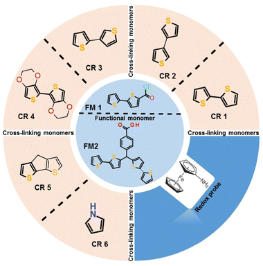
Electrochemical grade solvents [propylene carbonate, acetonitrile (ACN), and toluene], bovine serum albumin (BSA), human serum albumin (HSA), cytochrome c (from the equine heart), myoglobin, 2,2′-bithiophene-5-carbonyl chloride functional monomer (FM1), N,N′-dicyclohexylcarbodiimide (DCC), 2,3′-bithiophene, pyrrole, triethylamine, and lithium perchlorate were purchased from Merck Sigma. 1-Hydroxy-7-azabenzotriazole (HOAt) and aminoferrocene were acquired from TCI Chemicals. 2,2′-Bithiophene and 3,3′-bithiophene were obtained from Combi-Blocks Inc. 4H-Cyclopenta[1,2-b:5,4-b′]dithiophene and 2,2′,3,3′-tetrahydro-5,5′-bithieno[3,4-b][1,4]dioxine were purchased from Fluorochem Ltd. Silica beads (500 nm) were acquired from Fiber Optic Centre Inc. Analytical grade NaOH, NaCO3, NaHCO3, chloroform, and KF were from CHEMPUR. Hexaammineruthenium(III) chloride was purchased from abcr GmbH.Glass slides coated with thin layers of Au (150 nm) evaporated on Ti (15 nm) under layers (Au-glass slides) were used for polymer preparation. Synthetic details on preparing the p-bis(2,2′-bithien-5-yl)methylbenzoic acid FM2, used to derivatized BSA, are given elsewhere.30
2.2 Instruments
Langmuir–Blodgett (LB) transfer of silica beads was performed by a Langmuir trough type BAM 601 (rectangular, 7 × 75 cm2) controlled using NIMA TR620 software. An MPW Medical Instruments centrifuge model MPW-351R was used to centrifuge silica beads. The surface of Au plates was cleaned and hydrophilized by a Zepto plasma cleaner (100 W) from Diener Electronic.MIP films were imaged by scanning electron microscopy (SEM) using a Nova NanoSEM 450 microscope from FEI Nova. SECM measurements were performed with a home-build SECM system consisting of PIHera closed-loop piezo positioner (Physik Instrumente), two VA-10X patch-clamp amplifiers (npi Electronic Instruments) connected in a bipotentiostat, PCI-DAS1602/16, and PCI-DDA04 AD/DA cards (Measurement Computing) operating under SECMx software.31 In the SECM experiments, a Pt microelectrode, ca. 25 μm in diameter, was used as an SECM probe, while a silver chloride-covered silver wire served as a pseudo-reference electrode.
A SP-300 BioLogic potentiostat controlled using EC-Lab BioLogic software was used for electrochemical measurements. An Au-glass slide, an Ag|AgCl pseudo electrode, and a Pt plate was used as the working, reference, and auxiliary electrodes.
A PHI 5000 VersaProbe™ (ULVCPHI) scanning ESCA microprobe using monochromatic A1 Kα radiation (hν = 1486.4 eV) was used to record XPS spectra. The XPS data were recorded using a 100 μm diameter X-ray beam and collected from a 250 μm2 irradiated area. High-resolution XPS spectra were recorded with a hemispherical analyzer at a pass energy of 23.5 eV, an energy step of 0.1 eV, and a photoelectron take-off angle of 45° with respect to the surface plane. XPS data were analyzed using CASA XPS software. The Shirley method was used to subtract the background, and peaks were fitted using the mixed Gaussian Lorentzian method.
2.3 Methods
![[thin space (1/6-em)]](https://www.rsc.org/images/entities/char_2009.gif) :
:![[thin space (1/6-em)]](https://www.rsc.org/images/entities/char_2009.gif) 9 molar ratios (10 mM FM, 90 mM CR) in propylene carbonate containing 1 M LiClO4 for electrodeposition. In the case of CR5, a propylene carbonate–toluene mixture in 1
9 molar ratios (10 mM FM, 90 mM CR) in propylene carbonate containing 1 M LiClO4 for electrodeposition. In the case of CR5, a propylene carbonate–toluene mixture in 1![[thin space (1/6-em)]](https://www.rsc.org/images/entities/char_2009.gif) :
:![[thin space (1/6-em)]](https://www.rsc.org/images/entities/char_2009.gif) 1 ratio (v
1 ratio (v![[thin space (1/6-em)]](https://www.rsc.org/images/entities/char_2009.gif) :
:![[thin space (1/6-em)]](https://www.rsc.org/images/entities/char_2009.gif) v) was used due to low solubility.
v) was used due to low solubility.
![[thin space (1/6-em)]](https://www.rsc.org/images/entities/char_2009.gif) :
:![[thin space (1/6-em)]](https://www.rsc.org/images/entities/char_2009.gif) 1, v/v) for 1 hour. During this time, they were kept covered and stored at 4 °C to reduce evaporation. In the end, the plates were washed with a toluene/chloroform mixture to remove unreacted compounds and later with Milli-Q water (18 MΩ cm at 25 °C).
1, v/v) for 1 hour. During this time, they were kept covered and stored at 4 °C to reduce evaporation. In the end, the plates were washed with a toluene/chloroform mixture to remove unreacted compounds and later with Milli-Q water (18 MΩ cm at 25 °C).
![[thin space (1/6-em)]](https://www.rsc.org/images/entities/char_2009.gif) :
:![[thin space (1/6-em)]](https://www.rsc.org/images/entities/char_2009.gif) 4, v
4, v![[thin space (1/6-em)]](https://www.rsc.org/images/entities/char_2009.gif) :
:![[thin space (1/6-em)]](https://www.rsc.org/images/entities/char_2009.gif) v). The film was prepared over the air–water interface of the Langmuir trough filled with Milli-Q water. After the evaporation of solvents, the beads floating at the air–water interface were compressed with a barrier speed of 10 cm2 min−1 to the target LB transfer pressure of 7 mN m−1. Subsequently, these films were transferred using the LB technique during emersion at 1 mm min−1 dipper speed onto an Au-coated glass slide.
v). The film was prepared over the air–water interface of the Langmuir trough filled with Milli-Q water. After the evaporation of solvents, the beads floating at the air–water interface were compressed with a barrier speed of 10 cm2 min−1 to the target LB transfer pressure of 7 mN m−1. Subsequently, these films were transferred using the LB technique during emersion at 1 mm min−1 dipper speed onto an Au-coated glass slide.
Au plates covered with a silica colloidal crystal were immersed in a glutaraldehyde solution (2.5%) in phosphate buffer saline (pH = 7.4) for 1 h at room temperature for further immobilization of the protein. Then, the plates were washed three times with distilled water. Finally, the plates were immersed for 3 h at 4 °C in a solution of BSA (0.12 mg mL−1) in phosphate buffer saline (pH = 7.4). Repeated washing with phosphate buffer saline (pH = 7.4) and Milli-Q water removed the unbound protein.
![[thin space (1/6-em)]](https://www.rsc.org/images/entities/char_2009.gif) :
:![[thin space (1/6-em)]](https://www.rsc.org/images/entities/char_2009.gif) 1, v/v). These plates were washed repeatedly with an anhydrous toluene/chloroform mixture to remove unreacted reactants and monomers, then three times with Mili-Q water (18 MΩ cm at 25 °C), and finally with phosphate buffer saline (pH = 7.4).
1, v/v). These plates were washed repeatedly with an anhydrous toluene/chloroform mixture to remove unreacted reactants and monomers, then three times with Mili-Q water (18 MΩ cm at 25 °C), and finally with phosphate buffer saline (pH = 7.4).
After electropolymerization, the polymer samples were rinsed with methanol and then with water to remove any unreacted components and dried in air. A control, non-imprinted polymer (NIP) film was deposited on the protein-free colloidal crystal using the same polymerization solution composition and electropolymerization conditions. Polymer samples were dipped for 5 min in 5% HF to remove the silica mold. After removing the colloidal crystal, the template protein was extracted by washing with a 30% NaOH solution for 30 minutes.
The BSA extracted macroporous MIP-coated Au-glass slides were also used for BSA determination by capacitive impedimetric. The applied frequency and potential were held at f = 10 Hz and Eappl = 0.20 V vs. the Ag|AgCl pseudo-reference electrode, respectively. At such a low potential, no faradaic process was occurring. The BSA protein concentration was prepared by dissolving in 10 mM MES buffer (pH = 4.2). After water rinsing, the electrode was stored and dried when it was not in use.
3. Results and discussion
3.1 Selection of a suitable cross-linking monomer
In a preliminary study, several monomers were tested to find a suitable cross-linking monomer (Table 1). The electroactivity of such copolymers was measured after modifying carboxyl functionality with aminoferrocene. A substantial difference in the ferrocene signal was observed in these co-polymers (Fig. S1a, ESI†). It can be seen that in the case of 3,3′-bithiophene copolymer modified with aminoferrocene, a broad peak at a potential of 0.35 V vs. Ag/AgCl (Fig. S1a, ESI†) was observed. Moreover, energy dispersive X-ray spectroscopy (EDX) analysis showed that iron content was the highest in the co-polymer prepared with this monomer (Table 1). Another co-polymer prepared with 4H-cyclopenta[1,2-b:5,4-b′]dithiophene cross-linking monomer showed similar iron% after modification. However, ferrocene redox activity was not visible (Fig. S1b, ESI†). Probably, it was due to very high background currents observed even before modification with aminoferrocene. Other cross-linking monomer co-polymer's failed to show any ferrocene activity even though EDX confirmed the presence of iron (Table 1).| Cross-linker | Polymerization conditions (potential, charge passed) | Fe (atomic %) |
|---|---|---|
Concentrations of the cross-linking and functional monomer were 90 and 10 mM, respectively, during polymerization. Monomers were dissolved in propylene carbonate, except for the CR5 propylene carbonate–toluene mixture (1![[thin space (1/6-em)]](https://www.rsc.org/images/entities/char_2009.gif) : :![[thin space (1/6-em)]](https://www.rsc.org/images/entities/char_2009.gif) 1, v/v) was used, containing 1 M LiClO4. 1, v/v) was used, containing 1 M LiClO4. |
||
| 2,3′-Bithiophene | 1.0 V, 25 mC | 2.5 ± 0.2 |
| 2,2′-Bithiophene | 1.0 V, 25 mC | 4.4 ± 0.4 |
| 3,3′-Bithiophene | 1.2 V, 25 mC | 5.9 ± 0.4 |
| 4H-Cyclopenta[1,2-b:5,4-b′]dithiophene | 1.0 V, 25 mC | 6.0 ± 0.2 |
| 2,2′,3,3′-Tetrahydro-5,5′-bithieno[3,4-b] [1,4]dioxine | 1.0 V, 25 mC | 5.1 ± 0.2 |
| Pyrrole | 1.0 V, 25 mC | 5.0 ± 0.2 |
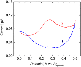
Ferrocene activity was not pronounced in the 3,3′-bithiophene (CR2) and FM1 co-polymers, possibly due to the low number of ferrocene moieties in the co-polymer after modification. Perhaps the incorporation of FM1 into the polymer matrix during cross-linking monomer polymerization was low. Such low redox activity can compromise the sensitivity of the chemosensor. Therefore, to increase the immobilized ferrocene population, the functional monomer was changed from FM1 to FM2 (Scheme 1). As can be seen from the recorded DPV in the case of the 3,3′-bithiophene and FM2 co-polymer, after modification with aminoferrocene, a well-defined redox peak at 0.25 V was observed (Fig. 1).
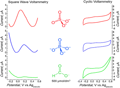
Later, the electrolyte influence on the redox activity of surface-immobilized ferrocene was studied. This study aimed to obtain a well-defined electrochemical signal in an environment that suits the final application. A peak was observed under non-aqueous conditions (Fig. 1). Low redox activity was observed when the electrochemical measurement was performed in H3PO4 (Fig. 2). Several other supporting electrolytes in an aqueous solution were tested. However, the redox activity of surface-immobilized ferrocene was the most prominent when the measurement was carried out in a 500 mM sulfuric acid solution.32 Therefore, a further experiment was performed in the presence of this electrolyte. However, the acid concentration was minimized to pose no threat to the stability of the protein. Reducing it by three orders of magnitude to 0.5 mM, resulting in a solution with pH = 3.0, still allowed the signal to be recorded as a clearly defined peak (Fig. 2). The electrode properties were also tested in a similarly diluted solution of HCOOH, an organic acid (Fig. 2), but the recorded currents were minor in this case.
The highest ferrocene signal in the presence of sulfate ions could be explained by the fact that oxidation to Fc+ is accompanied by the formation of Fc+–X− ion pairs due to the charge compensation of the surface-bound charged Fc+ by counter anions from the electrolyte.33 A lower signal of Fc with other electrolytes suggests that other anions were insufficient to compensate for the charge fully.
3.2 Semi-covalent surface imprinting
After finding suitable conditions for the electrochemical measurement of surface-immobilized ferrocene, semi-covalent surface imprinting was implemented, as described earlier.18 Briefly, it involves four steps, namely, (i) assembling of a monolayer of silica beads over the Au-coated glass slide, (ii) immobilization of the BSA protein template over silica beads, and (iii) derivatization of the surface-immobilized BSA protein with FM2, (iv) electrochemical cross-linking of FM2 with excess CR2. Removal of both the silica mold and protein template resulted in a macroporous structure containing imprinted molecular cavities on the polymer surface. Scheme 2 shows the execution of post-imprinting modification of the microcavities at the surface of the macroporous polymer.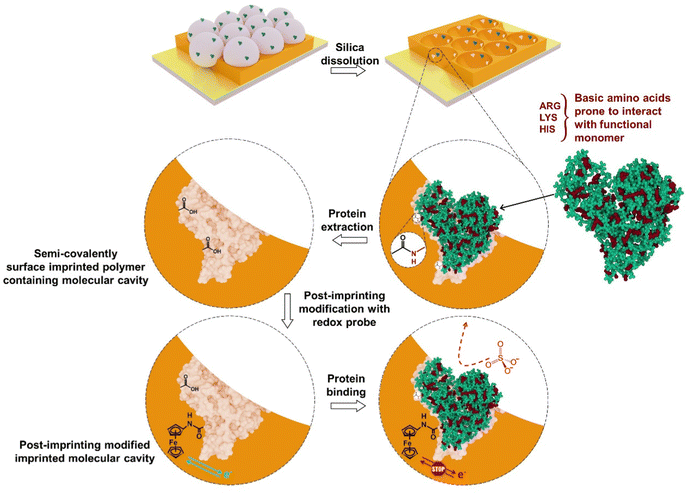 | ||
| Scheme 2 Post-imprinting modification of imprinted molecular cavities generated after semi-covalent surface imprinting of BSA. | ||
XPS measurement was performed at each preparation step. Table 2 summarizes the results of the atomic % of different elements measured. The presence of the N peak confirmed the modification of silica with the amine group. Nitrogen content increased to 7.3% after protein immobilization, confirming the effective immobilization of the BSA protein over the silica surface. The derivatization of surface-immobilized BSA, with the use of an FM2 functional monomer, carried out in the next step, was proven by the incorporation of sulphur at a concentration of 1.2%. The nitrogen content was measured in other samples, including imprinted polymers prepared only by surface imprinting and non-imprinted polymer (NIP). The Low N content of ∼1.7% found in the NIP is possibly due to residues of APTES or the adsorption of atmospheric nitrogen, as this sample was not exposed to other nitrogen containing reagents.
| Samples | O | N | C | Si | S | Fe |
|---|---|---|---|---|---|---|
| SiO2 | 61.9 | 0.6 | 8.5 | 29.0 | — | — |
| SiO2-BSA | 37.2 | 7.3 | 37.7 | 17.8 | — | — |
| SiO2-BSA-FM2 | 33.3 | 7.1 | 43.2 | 15.2 | 1.2 | — |
| Macroporous NIP | 12.3 | 1.7 | 77.6 | 0.0 | 8.4 | — |
| Surface imprinted polymer | 10.8 | 5.5 | 74.5 | 0.0 | 9.2 | — |
| Semi-covalently surface imprinted polymer | 10.8 | 6.6 | 74.2 | 0.0 | 8.4 | — |
| Semi-covalent surface imprinted polymer after post-imprinting modification | 23.0 | 8.3 | 56.4 | 0.0 | 3.8 | 8.5 |
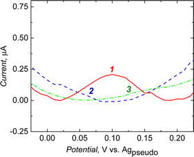
Macroporous polymers were XPS analyzed after post-imprinting modification with aminoferrocene (Table 2). The presence of iron was found in a macroporous imprinted polymer containing carboxyl groups in molecular cavities that can covalently bind the aminoferrocene. Electrochemical measurements revealed that the post-imprinting modified electrode showed redox activity (Fig. 3, curve 1). In contrast, on subjecting the macroporous NIP electrode to a similar modification step, there was no faradic current signal (Fig. 3, curve 3). Moreover, the sample prepared only with the surface imprinting approach did not show redox activity of ferrocene (Fig. 3, curve 2). Due to the absence of any functionalities in the polymer (only the cross-linker was deposited during surface imprinting and non-imprinted polymer preparation), no ferrocene groups were attached during the derivatization step. Therefore, we did not observe any electroactivity of ferrocene in the NIP sample. This proved that ferrocene moieties are being introduced only into imprinted cavities, not to the whole polymer volume.
For further support of FM2 and CR2, a new semi-covalently surface imprinted macroporous MIP was prepared with the combination of FM1 and CR3 cross-linking monomer. Fig. S2 (ESI†) summarises the results achieved when the post-imprinting modification with aminoferrocene was applied to the MIP prepared using CR3 and FM1 functional monomer. Faradic current originating from the oxidation of ferrocene appeared at 0.1 V (Fig. S2a, ESI†) for MIP prepared with FM2 and 3,3′-bithiophene (CR2) cross-linking monomer and broad peak for MIP prepared with FM1 and 2,3′-bithiophene (CR3). This difference was better pronounced in the SWV measurement. MIP prepared with FM2 and CR2 showed a well-defined peak (Fig. S2b, ESI†).
3.3 Morphological characterization of macroporous polymer
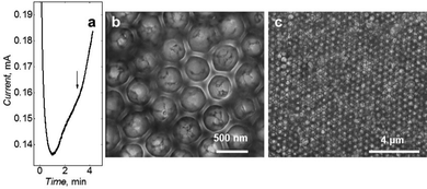
Potentiostatic deposition chronoamperogram (Fig. 4a) shows that polymerization was stopped after the current minima. This minimum current was observed because of the minimal active surface area of the growing polymer. SEM imaging confirmed the deposition of hexagonally arranged macroporous polymer (Fig. 4b and c). The regular arrangement was evident throughout the film. Based on the size of the pores generated after silica removal, it can be estimated that the film has been deposited up to half of the height of a single silica bead layer.3.4 Chemosesensor performance after post-imprinting modification
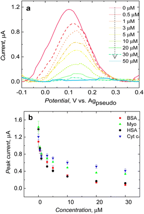
After clear visualization of ferrocene redox activity at a potential of ∼0.12 V vs. the Ag pseudo reference electrode, the study was extended to evaluate the performance of post-imprinting modified microcavities in electrochemical sensing. After introducing the BSA protein to the solution, the peak current decreased after reaching the BSA concentration of 0.5 μM. Furthermore, the current was dropping after subsequent BSA injection and almost reached zero at a BSA final concentration of 50 μM (Fig. 5a). It appeared that not only the peak current decreased with increasing BSA concentration, redox peak shifted slightly too, possibly due to slowing down of the kinetics of electrooxidation of immobilized ferrocene by proteins adsorption over the polymer surface, blocking access of electrolyte ions to the depolarizer.Analogous measurements carried out in the presence of common proteins, such as myoglobin, and cytochrome c, showed MIP microcavity selectivity (Fig. 5b). Redox probe signal significantly decreased when the HSA protein was introduced in solution; it is worth mentioning that the structure of the HSA protein is very similar to BSA.34 They share 75.6% sequence homology. This could be a reason for low selectivity (Fig. 5b). Current drops in the presence of other proteins were slightly less (Fig. 5b).
Although post-modified cavities did not show a high level of selectivity, one can expect such an outcome because the functionalities responsible for the selective recognition of proteins are now engaged in redox probe immobilization. Similarly, few reports showed a change in the selectivity of imprinted molecular cavities toward proteins by exchanging the functional group within the binding cavity using post-imprinting modification.14,35 Notably, post-imprinting confirms the concept and suggests that introducing redox probe tags is possible because of the functionality generated after protein removal by breaking amide bonds.
3.5 Chemosesensor performance measured before post-modification
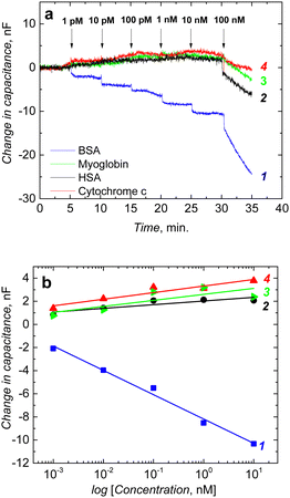
The fabricated chemosensor performance was tested before post-modification. BSA binding to its imprinted molecular cavities was confirmed through the capacitive impedimetric measurement in 10 mM MES (2-(N-morpholino)ethanesulfonic acid) buffer (pH = 4.2). These measurements were performed at the DC potential offset of 0.2 V and the AC potential amplitude of 10 mV. The frequency was kept constant at f = 10 Hz. After equilibrating the macroporous film, BSA protein solutions of different concentrations were added to the cell. A drop in capacitance corresponds to concentrations of the BSA protein in the solution. Chemosensor showed a logarithmic, linear response in the concentration range from 1 pM to 10 nM (Fig. 6a).The selectivity of the chemosensor was measured in the presence of typical proteins, including myoglobin, HSA, and cytochrome c. The selectivity of the macroporous MIP film was high, and it was able to recognize BSA template protein selectively (Fig. 6a). Interfering proteins, such as HSA, myoglobin, and cytochrome c, had small responses up to 10 nM (Fig. 6b).
Moreover, the macroporous MIP films show reasonable selectivity. Therefore, fabricated cavities were still able to recognize the shape of the BSA protein. Even though experimental conditions are far from physiological ones, we may assume that denaturing of the BSA protein is somewhat limited.
These chemosensing and selectivity results further support that functionality which was decisive for recognizing the BSA protein, was modified during post-imprinting modification steps and resulted in lower selectivity in electrochemical sensing. Post-imprinting modification appeared to be an efficient method to create synthetic receptors that operate in the protein-compatible medium i.e., water, for electrochemical sensing. Conditions used in the current approach were safe to avoid any denaturation of the protein. For instance, immobilization of BSA protein was performed in phosphate buffer saline. Therefore, during this step, any denaturation was not expected. During protein derivatization steps, toluene and chloroform were used. Proteins in hydrophobic solvents are thought to retain their native structure due to kinetic trapping, which results from stronger hydrogen bonding between the protein atoms and a more rigid structure in the absence of water.36
3.6 SECM study of the semi-covalently surface imprinted and non-imprinted macroporous polymer films
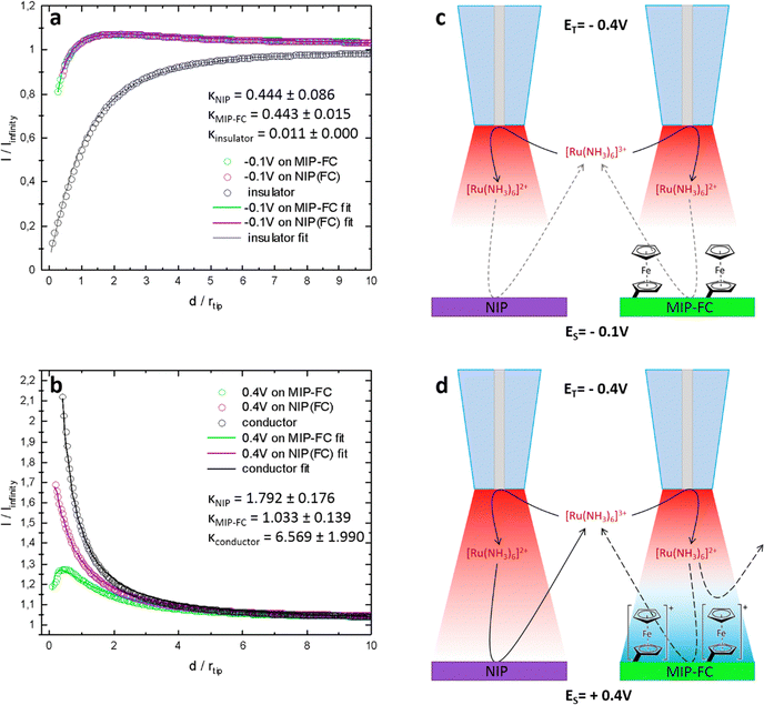
SECM was used to study the difference in the surface of semi-covalently imprinted and non-imprinted macroporous polymer films after modification with a ferrocene redox probe. It allows the characterization of the electrode–electrolyte interface. This study did not focus on a typical activity mapping but on the mediator regeneration kinetics at the sample utilizing the feedback mode. Here, we adapted the feedback mode. For measurements in feedback mode, a reversible redox probe is added to the supporting electrolyte as a mediator. By recording the tip current, while approaching the surface of the polymer samples with the tip and using the Cornut–Lefrou theoretical model,37 we gain the possibility of determining a dimensionless kinetic parameter K, which is directly dependent on the first-order heterogeneous effective rate constant of mediator regeneration on the polymer sample surface keff (K = keff·rT/D, rT-tip radius, D-diffusion coefficient of the redox mediator).Silver wire in the electrolyte containing 0.1 M KCl served as a quasi-reference counter electrode, whose potential was stable during the experiment when only nanoamp-range currents were flowing through it. The first working electrode was a Pt microelectrode (tip), used for recording approach curves, on which diffusion-controlled mediator reduction was carried out (Fig. S3, ESI†). The second working electrode was post-imprinted modified or NIP polymer-coated Au, polarized at −0.1 V or +0.4 V during the study. Depending on the applied potential, the mediator's redox reaction occurs on the polymer deposited Au electrode at different rates. At the same time, independently from the reaction of the mediator, by changing the potential bias of the sample, we can affect the status of the ferrocene redox probe covalently immobilized on the polymer surface. The SECM analysis aimed to confirm the modification of imprinted molecular cavities (Fig. 7).
Moreover, it could confirm the binding site generation after breaking the semi-covalent bond between functional monomers and proteins. For this purpose, a low potential, reducible, positively charged hexaamineruthenium(III) ion, Ru(NH3)63+, was selected as a mediator (Fig. S4, ESI†). A potential of −0.4 V vs. Agpseudo was applied to the Pt microelectrode tip during measurements, assuring a diffusion-limited reduction of the Ru(NH3)63+ mediator (Fig. S4, ESI†). Both porous polymers, non-imprinted (NIP) and semi-covalently surface imprinted with BSA (BSA extracted MIP film) were tested after aminoferrocene modification under two applied potentials, −0.1 V and +0.4 V vs. the Ag pseudo reference electrode in SECM measurements.
The curves presented in Fig. 7 show the value of the normalized tip current (current recorded divided by the steady-state current in the bulk electrolyte) plotted against the normalized distance (distance divided by the tip radius) from the sample surface. For the sample electrodes (imprinted cavities modified with the ferrocene or control polymer), polarized at −0.1 V. This potential [higher than the formal potential of the Ru(NH3)63+ mediator (ca. −0.2 V vs. Agpseudo, Fig. S4, ESI†)] is high enough to provide conditions for fast regeneration of the mediator at conductor whereas too low for oxidation of ferrocene moieties in the polymer, the current responses obtained were almost identical for both polymer samples (Fig. 7a, green and purple curves). With a well-conductive substrate, we should observe current enhancement (positive feedback) resulting from fast regeneration of the oxidized form of the mediator at the sample by an increase in the concentration of the oxidized form of the mediator Ru(NH3)63+ by the oxidation of Ru(NH3)63+ (Fig. 7b, black curve).
The current enhancements were insignificant (slow regeneration of the mediator at the samples, K ∼0.44) in the experiment when the applied potential on the samples was −0.1 V. Fig. 7a, the black curve represents, for comparison, a situation where no regeneration of mediator occurred at the sample (negative feedback). The slow regeneration of the mediator may be due to the poor conductivity of the polymer. The kinetic parameters for both samples were almost identical and equal to 0.44 ± 0.09 and 0.44 ± 0.02, respectively, for the control and imprinted polymer (Fig. 7c). This shows that the ferrocene moieties present in the MIP do not contribute to charge transfer between the electrode and electrolyte when they are in a reduced state (non-charged).
In the second series of measurements, different current behaviours were observed when the samples were biased at 0.4 V. Firstly, during the approach, an apparent current enhancement was noticeable only for the NIP sample. This can be explained by a sufficiently large positive overpotential applied to the sample, required for the effective oxidation of the reduced mediator at an imperfectly conductive polymer. The difference between the post-imprinting modified polymer and NIP appeared most likely due to the ferrocene moieties on the surface of the semi-covalently surface imprinted sample. After applying a potential of +0.4 V, the ferrocene present on the electrode was oxidized to its positively charged form. The presence of oxidized ferrocene on the surface of the imprinted polymer inhibits mediator oxidation. This may happen due to the electrostatic repulsive interactions between the positively charged ferrocene moieties and the positively charged Ru(NH3)63+ mediator (Fig. 7d).
Under similar conditions, this inhibition does not occur over the NIP surface (ferrocene modification was not possible because of the absence of any functionality and imprinted molecular cavities in the polymer), and the recorded approach curve was close to the feedback response of a typical conductor surface (Fig. 7b, violet and black curves). The kappa parameters for the NIP and the ferrocene-modified imprinted polymer determined after fitting the theoretical model were equal to 1.79 ± 0.18 and 1.03 ± 0.14, respectively. Slower kinetics were observed in the target polymer samples compared to the conductive surface (Fig. 7b, black curve). The fact that NIP was not labelled with ferrocene, proves that ferrocene moieties were not introduced to the whole volume of the MIP film but only to the imprinted molecular cavities.
These observations (Fig. 7) and the results of the SWV measurements (Fig. 5), in which the ferrocene electrochemical oxidation peak was obtained only in the case of the semi-covalently surface imprinted polymer, confirm that ferrocene was successfully introduced into the imprinted molecular cavities containing carboxyl groups. These carboxyl groups were generated after breaking the covalent bond between proteins and functional monomers. Measurement performed at the NIP-modified electrode additionally supported that semi-covalently surface imprinted macroporous film contains recognition sites that could be further modified to generate the electrochemical signal.
4. Conclusions
We have successfully realized a post-imprinting modification methodology for designing microcavities with the capabilities of fine-tuning the redox probe population. This tunability was exploited to study the effect of the cross-linking monomer electroactivity on the final polymer and immobilized ferrocene. Our results suggested that a set of parameters determine the electrochemical activity of the redox probe-modified macroporous MIP film. A suitable electrolyte was necessary for visualizing redox activity. Classical electrochemical and SECM techniques confirmed the efficiency of post-modification of imprinted molecular cavities.Moreover, SECM feedback current enhancement was observed with the NIP surface, not on the post-imprinting modified MIP surface, due to the presence of positively charged, oxidized surface-bound ferrocene moieties. The kinetics of the mediator regeneration was almost 1.8 times higher on the NIP surface versus post-imprinting modified MIP. Capacitive impedimetric transduction demonstrated that molecular cavities generated after semi-covalent surface imprinting were selective toward BSA, not for others such as HSA, myoglobin, and cytochrome c.
Conflicts of interest
There are no conflicts to declare.Acknowledgements
We thank Prof. Wojciech Lisowski (Institute of Physical Chemistry Polish Academy of Sciences) for XPS measurements. The present research was financially supported by the National Science Centre (Grant No. NCN 2017/25/B/ST4/01696 to P.S.S.). W. N. is grateful to the National Science Centre (NCN, Poland) for support through grant UMO-2016/23/B/ST4/02868.References
- J. Xu, H. Miao, J. Wang and G. Pan, Small, 2020, 1906644 CrossRef CAS PubMed.
- R. Mahajan, M. Rouhi, S. Shinde, T. Bedwell, A. Incel, L. Mavliutova, S. Piletsky, I. A. Nicholls and B. Sellergren, Angew. Chem., 2019, 131, 737–740 CrossRef.
- Y. He and Z. Lin, J. Mater. Chem. B, 2022, 10, 6571–6589 RSC.
- M. Dabrowski, P. Lach, M. Cieplak and W. Kutner, Biosens. Bioelectron., 2018, 102, 17–26 CrossRef CAS PubMed.
- B. T. S. Bui, T. Auroy and K. Haupt, Angew. Chem., Int. Ed., 2022, 61, e202106493 Search PubMed.
- J. Qi, B. Li, N. Zhou, X. Wang, D. Deng, L. Luo and L. Chen, Biosens. Bioelectron., 2019, 142, 111533 CrossRef CAS PubMed.
- C. Baggiani, C. Giovannoli, L. Anfossi, C. Passini, P. Baravalle and G. Giraudi, J. Am. Chem. Soc., 2012, 134, 1513–1518 CrossRef CAS PubMed.
- R. J. Umpleby II, M. Bode and K. D. Shimizu, Analyst, 2000, 125, 1261–1265 RSC.
- K. J. Shea, G. J. Stoddard, D. M. Shavelle, F. Wakui and R. M. Choate, Macromolecules, 1990, 23, 4497–4507 CrossRef CAS.
- M. J. Whitcombe, M. E. Rodriguez, P. Villar and E. N. Vulfson, J. Am. Chem. Soc., 1995, 117, 7105–7111 CrossRef CAS.
- M. Lübke, M. J. Whitcombe and E. N. Vulfson, J. Am. Chem. Soc., 1998, 120, 13342–13348 CrossRef.
- B. Sellergren, J. Org. Chem., 1990, 55, 3381–3383 CrossRef CAS.
- P. Qi, J. Wang, L. Wang, Y. Li, J. Jin, F. Su, Y. Tian and J. Chen, Polymer, 2010, 51, 5417–5423 CrossRef CAS.
- R. Horikawa, H. Sunayama, Y. Kitayama, E. Takano and T. Takeuchi, Angew. Chem., Int. Ed., 2016, 55, 13023–13027 CrossRef CAS PubMed.
- J. Bognar, J. Szucs, Z. Dorko, V. Horvath and R. E. Gyurcsanyi, Adv. Funct. Mater., 2013, 23, 4703–4709 CrossRef CAS.
- P. Curcio, C. Zandanel, A. Wagner, C. Mioskowski and R. Baati, Macromol. Biosci., 2009, 9, 596–604 CrossRef CAS PubMed.
- M. Dąbrowski, A. Zimińska, J. Kalecki, M. Cieplak, W. Lisowski, R. Maksym, S. Shao, F. D’Souza, A. Kuhn and P. S. Sharma, ACS Appl. Mater. Interfaces, 2019, 11, 9265–9276 CrossRef PubMed.
- J. Kalecki, M. Cieplak, M. Dąbrowski, W. Lisowski, A. Kuhn and P. S. Sharma, ACS Sens., 2020, 5, 118–126 CrossRef CAS PubMed.
- M. Dabrowski, M. Cieplak, P. S. Sharma, P. Borowicz, K. Noworyta, W. Lisowski, F. D'Souza, A. Kuhn and W. Kutner, Biosens. Bioelectron., 2017, 94, 155–161 CrossRef CAS PubMed.
- J. Kalecki, Z. Iskierko, M. Cieplak and P. S. Sharma, ACS Sens., 2020, 5, 3710–3720 CrossRef CAS PubMed.
- T. Takeuchi and H. Sunayama, Chem. Commun., 2018, 54, 6243–6251 RSC.
- H. Sunayama and T. Takeuchi, Chromatography, 2021, 42, 73–81 CrossRef CAS.
- H. Lu, D. Wei, R. Zheng and S. Xu, Analyst, 2019, 144, 6283–6290 RSC.
- T. Mukawa, T. Goto and T. Takeuchi, Analyst, 2002, 127, 1407–1409 RSC.
- P. Sun, F. O. Laforge and M. V. Mirkin, Phys. Chem. Chem. Phys., 2007, 9, 802–823 RSC.
- G. Wittstock, M. Burchardt, S. E. Pust, Y. Shen and C. Zhao, Angew. Chem., Int. Ed., 2007, 46, 1584–1617 CrossRef CAS PubMed.
- M. V. Mirkin, W. Nogala, J. Velmurugan and Y. Wang, Phys. Chem. Chem. Phys., 2011, 13, 21196–21212 RSC.
- D. Polcari, P. Dauphin-Ducharme and J. Mauzeroll, Chem. Rev., 2016, 116, 13234–13278 CrossRef CAS PubMed.
- C. M. Hanna, C. D. Sanborn, S. Ardo and J. Y. Yang, ACS Appl. Mater. Interfaces, 2018, 10, 13211–13217 CrossRef CAS PubMed.
- T.-P. Huynh, A. Wojnarowicz, M. Sosnowska, S. Srebnik, T. Benincori, F. Sannicolò, F. D'Souza and W. Kutner, Biosens. Bioelectron., 2015, 70, 153–160 CrossRef CAS PubMed.
- C. N. Kirchner, K. H. Hallmeier, R. Szargan, T. Raschke, C. Radehaus and G. Wittstock, Electroanalysis, 2007, 19, 1023–1031 CrossRef CAS.
- G. S. Mohammad-Pour, K. O. Hatfield, D. C. Fairchild, K. Hernandez-Burgos, J. Rodríguez-López and F. J. Uribe-Romo, J. Am. Chem. Soc., 2019, 141, 19978–19982 CrossRef CAS PubMed.
- R. A. Wong, Y. Yokota, M. Wakisaka, J. Inukai and Y. Kim, Nat. Commun., 2020, 11, 4194 CrossRef PubMed.
- R. Maier, M. R. Fries, C. Buchholz, F. Zhang and F. Schreiber, Cryst. Growth Des., 2021, 21, 5451–5459 CrossRef CAS.
- H. Sunayama, Y. Kitayama and T. Takeuchi, J. Mol. Recognit., 2018, 31, e2633 CrossRef PubMed.
- C. Mattos and D. Ringe, Curr. Opin. Struct. Biol., 2001, 11, 761–764 CrossRef CAS PubMed.
- R. Cornut and C. Lefrou, J. Electroanal. Chem., 2008, 621, 178–184 CrossRef CAS.
Footnote |
| † Electronic supplementary information (ESI) available. See DOI: https://doi.org/10.1039/d2tb02116a |
| This journal is © The Royal Society of Chemistry 2023 |

