Nanoporous ices: an emerging class in the water/ice family
Yuan
Liu
 *a,
Yangyang
Pu
a and
Xiao Cheng
Zeng
*bc
aSchool of Chemical Engineering and Technology, Sun Yat-Sen University, Zhuhai 519082, China. E-mail: liuy2265@mail.sysu.edu.cn
bDepartment of Materials Science & Engineering, City University of Hong Kong, Kowloon, 999077, Hong Kong. E-mail: xzeng26@cityu.edu.hk
cDepartment of Chemistry, University of Nebraska-Lincoln, NE 68588, USA
First published on 28th November 2022
Abstract
The history of scientific research on diverse ice structures dates back to more than a century. To date, 20 three-dimensional crystalline ice phases (ice I-ice XX) have been identified in the laboratory, among which ice XVI and ice XVII belong to a class of low-density nanoporous ices. Nanoporous ices can also be viewed as a special class of porous materials or water ice, as they possess a relatively high fraction of nano-cavities and/or nano-channels built into the hydrogen-bonded water framework. As such, like the prototypical class of porous materials (e.g., MOFs and COFs), nanoporous ices can be named as water oxygen-vertex frameworks (WOFs). Because of their large surface-to-volume ratio, WOFs may be potential media for gas storage, gas purification and separation. They may be applied to the biomedical field owing to their excellent biocompatibility. The field of porous ices is still emerging, as many porous ice structures that are predicted to be stable by computer simulations require future experimental confirmation. For future theoretical/computational studies, as the machine-learning method becomes an increasingly popular research tool in the material science and chemical science fields, more reliable porous ice structures and phase diagrams will be predicted with the development of more accurate machine-learning force fields.
1. Introduction
Nanoporous ices are a special class of porous materials with a high fraction of nano-cavities and/or nano-channels built into hydrogen-bonded water frameworks. These low-density ices were discovered in recent years;1,2 hence, becoming a new class in the water/ice family, as well as in the porous material family. Like the prototypical classes of porous materials (e.g., MOFs (metal organic frameworks)3 and COFs (covalent organic frameworks)4), nanoporous ices can be also named as WOFs (water oxygen-vertex frameworks).2 Because of their high surface-to-volume ratio, WOFs may find applications in gas storage, gas purification and separation.5,6 They may also be potential media for bio- or medical delivery owing to their excellent biocompatibility.Research studies on nanoporous ices have gained increasing attention in the field of water science,7,8 motived in part by the intensive studies of low-dimensional ices,9–14 heterogeneous ice nucleation on surfaces,15–18 as well as gas clathrate hydrates.19–24 The latter belongs to a class of host–guest compounds with the hydrogen-bonded water framework as the host, while the nano-cavities embedded in the frameworks are occupied by gas molecules as the guest.25,26 The most well-known gas clathrate hydrates are methane clathrate hydrates, which are composed of methane molecules encapsulated in various hydrogen-bonded water polyhedral cavities. Abundant amounts of methane clathrate hydrates are largely deposited under the ocean floor and the permafrost zones on the Earth. Hence, this natural-gas reserve has been considered as a promising and alternative fossil-fuel energy source.25–27 Hydrogen clathrate hydrates are another well-known host–guest compound, which has been synthesized in the laboratory and considered as potential green-hydrogen storage.28–31 In previous studies of gas clathrate hydrates, some researchers calculated the thermodynamic properties of the guest-free clathrate hydrates. They found that the well-known clathrate hydrate sII can be guest-free, while it is still stable under negative pressure.32,33 Later, Falenty et al. fabricated the guest-free clathrate hydrate sII by pumping off the Ne guest atoms from the already synthesized Ne clathrate hydrate of type sII.34 The successfully attained guest-free clathrate hydrate sII was named as ice XVI (whose structure is shown in Fig. 1A). Ice XVI is the first experimentally produced nanoporous ice, and its discovery opens the door for later research on nanoporous ices.
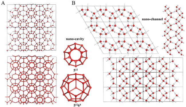 | ||
| Fig. 1 (A) Molecular structure of the guest-free clathrate sII, also named as ice XVI, which exhibits two types of polyhedral nano-cavities (512 and 51264). (B) Molecular structure of ice XVII, which exhibits spiraling nano-channels. Note: the atomic coordinates of ice XVI and XVII are taken from ref. 34 and 37, respectively, measured from neutron diffraction experiments. | ||
This minireview focuses on the recent research progress and important research milestone in both experimental and theoretical studies of nanoporous ices. In the end, we summarize perspectives on future studies in the field of nanoporous ices.
2. Experimental discoveries of nanoporous ices
The experimental effort to fabricate nanoporous ices was initially inspired by the computer simulations. Based on molecular dynamics (MD) simulations with the monoatomic water force field, Jacobson et al. constructed a phase diagram of water and suggested that the guest-free sII clathrate hydrate can be stable at pressures lower than −1300 atm and temperatures lower than 275 K. However, even in the stable region (e.g., −2000 atm and from 275 K to 160 K) of the guest-free sII clathrate, the liquid water would spontaneously crystallize to ice Ih, indicating that the direct nucleation of guest-free clathrate from liquid water is highly unlikely due to the lower nucleation barrier of ice Ih than that of water clathrate.32 Alternatively, they proposed two approaches to making the guest-free clathrate in the laboratory: (1) achieving empty water clathrates by removing the hydrogen from hydrogen hydrates, or (2) achieving the guest-free clathrates through template-based growth by using a conventional clathrate hydrate as the template.32Following the proposed strategy by Jacobson et al., Falenty et al. synthesized neon clathrate hydrate of type sII, and pumped off all the guests in the sample of Ne hydrate. Remarkably, they found that the guest-free sII clathrate was stable below 145 K, and the empty sII clathrate exhibited negative thermal expansion below 55 K.34 The obtained guest-free clathrate hydrate of sII was named as ice XVI (see Fig. 1A). It contained face-sharing polyhedral water nano-cavities, namely, 512 formed by 12 pentagons and 51264 formed by 12 pentagons and 4 hexagons, with the estimated volume of 160 and 307 Å3, respectively.34 Ice XVI is the first experimentally confirmed nanoporous ice phase.
Similar to the approach to producing ice XVI, ice XVII (Fig. 1B) was achieved by removing the hydrogen molecules of a hydrogen filled ice hydrate in the laboratory, and ice XVII is also a nanoporous ice with intriguing spiraling nanochannels whose estimated diameter is 6.10 Å.35,36 Notably, the nanochannels can reversibly adsorb and desorb hydrogen molecules in the gas, rendering the ice XVII a potential medium for hydrogen storage.35 The adsorption of O2 and Ne in the spiraling nano-channels of ice XVII was also studied by using an in situ neutron diffraction measurement.37 In addition, it was found that cubic ice Ic with high structural purity can be obtained in large quantity by heating the powder of ice XVII.38,39
3. Theoretical predictions of nanoporous ices
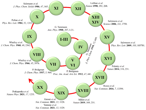
Due to the high flexibility of the hydrogen bonds between the water molecules, a variety of hydrogen-bonded topological networks can form during the liquid water freezes into solid ice. As presented in Fig. 2, 20 three-dimensional crystalline ice phases have been experimentally confirmed to date after investigation for more than a century.40–43 Among the 20 ice phases, only ice XVI and ice XVII belong to low-density nanoporous ices. The field of nanoporous ices is still very young, and little is known about how many realistic crystalline phases of porous ices could be found or confirmed in nature. As the field was initiated from computer simulation, it is expected that many more porous ice structures will be predicted based on density functional theory computations and molecular dynamics simulations.3.1. Predictions of stable nanoporous ice phases based on free-energy computation
Conde et al. constructed a phase diagram of water at negative pressures by performing free energy computations and Gibbs–Duhem thermodynamic integration.33 Two phase diagrams were determined from the computer simulations by using the water force fields of TIP4P/2005 and TIP5P. The guest-free clathrate hydrates sII and sH were predicted to be stable phases under negative pressures.33 Five years later, the guest-free sII was experimentally confirmed (named as ice XVI) by Falenty et al.34 The cubic unit cell of ice XVI consists of 16 dodecahedral cavities (512) and 8 hexakaidecahedral cavities (51264). The guest-free sH is also built up by face-sharing polyhedral water nano-cavities. Its hexagonal unit cell consists of three dodecahedral cavities (512), two irregular dodecahedral cavities (435663), and one icosahedral cavity (51268).26 In the phase diagram, the phase of guest-free clathrate hydrate sII is located at moderately negative pressures under the region of ice XI and Ih. Meanwhile, the guest-free clathrate hydrate sH is the stable phase at deeper negative pressure below the guest-free sII phase.33Interestingly, Huang et al. reconstructed the water phase diagram under negative pressure based on the TIP4P/2005 water model, and predicted an empty clathrate, named as sIII, to be stable in the pressure region below −5834 bar at 0 K and below −3411 bar at 300 K. sIII is also located below the guest-free sII phase, and in place of the original stable region of guest-free sH in the previous phase diagram.44 As shown in Fig. 3A, the guest-free clathrate sIII consists of polyhedral water nano-cavities (4126886) connected to each other through hydrogen bonds, and has a ultralow mass density of 0.6 g cm−3. Later, Liu and Ojamäe predicted a new structure, named as sL, based on first-principles phase diagram computations, to be more stable than sIII. Thus, sL occupies the region below the guest-free sII in the phase diagram, as shown in Fig. 3B and C.45 Based on the phase diagram computation, the phase transition pressure from sII to sL is −5170 bar at 0 K and −4761 bar at 300 K. In contrast, the phase transition between sII and sL would occur at less negative pressure than that between sII and sIII. Thus, the sIII phase was replaced by sL in the phase diagram.45 As depicted in Fig. 3A, the sL structure consists of 4126886 water nano-cavities as well, but it is formed by 4126886 water cavities through fusing the octagons together, instead of connecting octagons of the 4126886 cages by hydrogen bonds in sIII.
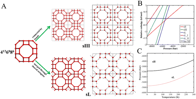 | ||
| Fig. 3 (A) Molecular structures of sIII and sL, both having the same type of nano-cavity 4126886. sIII is formed by the hydrogen-bonding connection among the 4126886 cavities. In the structure of sL, the 4126886 cavities are merged together through shared octagons. (B) A phase diagram at 0 K for several clathrate ices with ice XI as the reference. (C) Pressure versus temperature phase diagram of clathrate ices, predicted from first-principles computations. The solid line is the phase boundary between guest-free clathrate sII and clathrate ice sL, and the dashed line is the phase boundary between sII and sIII. This figure has been adapted/reproduced from ref. 45 with permission from Royal Society of Chemistry. | ||
It should be noted that some ultralow-density ices only maintain their crystalline structure within a narrow pressure and temperature range, even though they were predicted to be thermodynamically metastable in a larger pressure–temperature region based on free energy calculations.46 As shown in Fig. 4A, for example, the LTA appears to be the most stable phase for pressure < −3.8 kbar since the Gibbs free energy of the LTA structure was the lowest one among the structures considered. However, the LTA structure would be disrupted at the pressures < −4.0 kbar within 10 ns in the MD simulations.46 Hence, as depicted in Fig. 4B, the LTA structure could only exist in the very narrow pressure range from −4.0 to −3.8 kbar due to its mechanical instability at pressure < −4.0 kbar.46 Indeed, Matsui et al. pointed out that one should consider both the thermodynamic and mechanical stabilities of the nanoporous ices when constructing the water phase diagram at negative pressure.46 As depicted in Fig. 4C, a phase diagram of water in the negative pressure region was constructed using the TIP4P/2005 water model after evaluating the mechanical stabilities of nanoporous ices.46,47 Notably, the phase diagram was sliced into many pieces due to the mechanical instability.
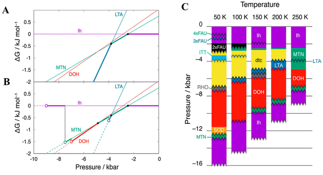 | ||
| Fig. 4 (A) Gibbs energies of ices MTN (clathrate sII), DOH (clathrate sH), and LTA (clathrate sL) relative to that of ice Ih at 250 K. Filled circles refer to the phase transition points of two phases. Thick lines indicate the most stable phases among the phases determined based on Gibbs free energy calculations. (B) Gibbs energies of ices MTN, DOH, and LTA relative to that of ice Ih at 250 K. Open circles refer to the pressure limits of mechanical stability. Dashed lines represent the mechanically unstable region. (C) Phase diagram of water at negative pressure after considering the mechanical stability when using the. TIP4P/2005 water model. This figure has been adapted/reproduced from ref. 46 with permission from AIP Publishing, copyright 2019. | ||
3.2. Screening of stable nanoporous ice structures from a large number of candidates generated from the zeolitic structure database
Another effective approach to predict nanoporous ice structures is to take advantage of the database of known structures of zeolites, from which analogous structural models of nanoporous ices can be generated first.48,49 This approach is sensible because the tetrahedral frameworks of the oxygen atoms of water molecules in nanoporous ices have been reported to be isostructural with the silicon atom networks of silica.50,51 It has also been found that silica clathrate minerals have the same structural frameworks with ice clathrate hydrates, i.e., MEP with sI, MTN with sII, and DOH with sH.52 Moreover, the guest-free silicon, germanium, and alloyed Si–Ge clathrates of sII type have been synthesized in the laboratory.53–55 Therefore, a large number of porous ice candidates can be generated by simply mapping the known tetrahedral frameworks of zeolite structures to nanoporous ice structures. The stable porous ices can be screened from these candidates via thermodynamic computations.Tribello et al. reported the isomorphism between ice and silica, and indicated that hypothetical ice clathrates can be constructed from silica structures.51 Later, Matsui et al. constructed many porous ice candidates from zeolite frameworks and space fullerenes.56 After examination of all structural candidates based on MD simulations, they found that the ice ITT generated from zeolite ITT was more stable than the s-IV ice clathrate previously predicted by Huang et al.57 They also reported a class of low-density porous ices with the name of aeroices by extending the zeolite FAU structure.56 Based on the tetrahedral networks of the synthesized zeolites included in the IZA-SC database, Liu et al. generated more than 200 hypothetical zeolite-like porous ice structures, and screened out two porous ice phases (FAU and EMT) with ultralow density (∼0.5 g cm−3). Both appear to be stable phases in the phase diagram at deep negative pressures,1 as shown in Fig. 5A–E. Among the ultra-low density nanoporous ices, the superheating limit of the ITT structure was 60 K lower than that of the FAU and EMT structures based on simulated thermal stability tests from MD simulations. The relatively low thermal stability of the ITT structure is probably due to the relatively high local strain induced by the three-membered rings in the hydrogen-bonded framework of the ITT structure.1 In view of the larger cavities with the average radius values of 7.16 Å and 7.88 Å in the structures of FAU and EMT, respectively, both nanoporous ices may find applications for hydrogen storage. As shown in Fig. 5F, the hydrogen storage capacity of the EMT ice amounts to 12.9 wt% based on the first-principles computations of H2 adsorption energy. This weight percentage value is two times higher than the 2020 DOE target value (4.5 wt%).1
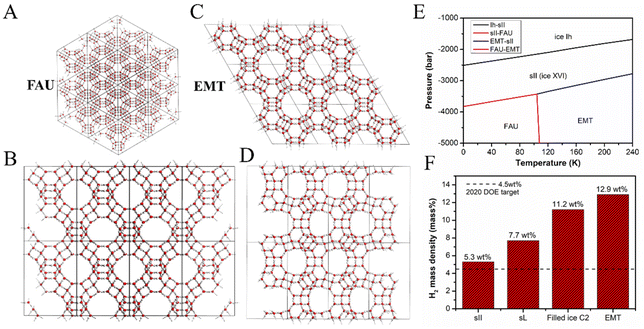 | ||
| Fig. 5 (A) Molecular structure of zeolitic ice FAU from a point view of a vertex. (B) Sideview of the structure of FAU. (C) Top view of the zeolitic ice EMT. (D) Sideview of the structure of EMT. (E) Pressure versus temperature phase diagram of water at the negative pressure region. (F) Hydrogen storage capacities of clathrate ice sII, sL, and EMT, and filled ice C2. This figure has been adapted/reproduced from ref. 1 with permission from National Academy of Sciences, copyright 2019. | ||
Recently, Engel et al. screened 34 ice candidates from more than 15![[thin space (1/6-em)]](https://www.rsc.org/images/entities/char_2009.gif) 000 tetrahedral networks listed in the databases of Treacy, Deem, and the International Zeolite Association by the first-principles calculations and the “generalised convex hulls” construction assisted by machine learning method, further demonstrating the effectiveness of predicting new nanoporous ice structures by taking advantage of the known zeolitic structures.58
000 tetrahedral networks listed in the databases of Treacy, Deem, and the International Zeolite Association by the first-principles calculations and the “generalised convex hulls” construction assisted by machine learning method, further demonstrating the effectiveness of predicting new nanoporous ice structures by taking advantage of the known zeolitic structures.58
3.3. Spontaneous formation of nanoporous ices with an array of carbon nanotubes as the scaffold
As described above, many nanoporous ice structures have been predicted to be stable by screening a large number of zeolite-like candidate structures via thermodynamic computations.1,56,58 As presented in the phase diagram, the nanoporous ice phases are generally stable at negative pressures.1,2,32,33,44,45 The direct formation of these nanoporous ices from liquid water at negative pressure, however, is very unlikely.32,34 Motivated by the approaches for synthesizing porous materials based on the host–guest chemistry, Liu et al. predicted a class of ultralow-density porous ices in which the up-right nano-channels were spontaneously formed from liquid water at room temperature with the assistance of carbon nanotube (CNT) arrays as the scaffold in their MD simulations.2 The structural model is shown in Fig. 6. In the simulations, zigzag CNTs from (3, 0) to (18, 0) with diameters ranging from 0.2 nm to 1.4 nm and a length of 8.0 nm were employed in the form of a hexagonal array, as shown in Fig. 7A. Ten porous ice structures (WOF 0_a, I_a–I_c, II_a–II_c, I_a′, and mixed phases I_b & I_c and I_c & II_b) were observed through the spontaneous liquid–solid phase transitions by tuning the inter-CNT spacings during the extensive search of MD simulations (Fig. 7B–D).2 Interestingly, the estimated freezing temperatures of these nanoporous ices were above 300 K by using TIP4P/Ice water model (the melting temperature of bulk ice Ih is 272 K with the TIP4P/Ice model).59 Moreover, these nanoporous ice structures can be viewed as assemblies of nanoribbons of two-dimensional hexagonal bilayer ice (2D ice I)13 at their armchair or zigzag edges, and the upright nanochannels of these nanoporous ices are suitable for the occupation of CNTs.2 The nanoporous ices could be applied as gas storage materials since they are still stable even after all of the guest CNTs are removed at suitable pressure–temperature conditions. In particular, based on the thermal stability examination by using MD simulations, WOF I_f (whose structure had the lowest mass density of 0.32 g cm−3 among the WOFs) with exceptionally high gravimetric and volumetric hydrogen storage capacities (27.5 wt% and 111.7 g L−1) was predicted to be stable up to 100 K and 5 bar, and could find application for H2 storage at relatively low pressure.2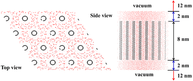 | ||
| Fig. 6 Structural model examined in the spontaneous formation of nanoporous ices based on MD simulations. This figure has been adapted/reproduced from ref. 2 with permission from National Academy of Sciences, copyright 2021. | ||
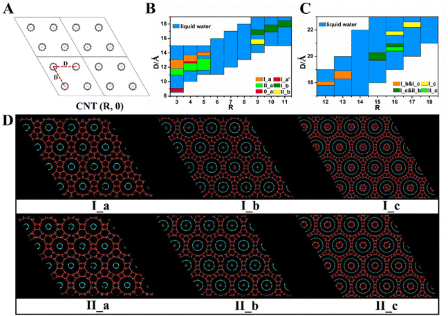 | ||
| Fig. 7 (A) The guest scaffold – CNT (R, 0) array with the inter-CNT spacing D arranged in the form of a hexagonal lattice. (B) Structural search of the nanoporous ices with various diameters of CNT (R, 0) (R = 3 to 11) and inter-CNT spacing D. (C) Structural search of the nanoporous ices with various diameters of CNT (R, 0) (R = 12 to 18) and inter-CNT spacing D. (D) Six distinct hexagonal porous ices spontaneously formed in the MD simulations at a constant temperature of 300 K. This figure has been adapted/reproduced from ref. 2 with permission from National Academy of Sciences, copyright 2021. | ||
Recently, based on MD simulations, Matsumoto et al. investigated water freezing by using different scaffold models, e.g., the armchair CNTs with a range of CNT indexes from (2, 2) to (16, 16), and the zigzag CNTs with a range of CNT indexes from (3, 0) to (19, 0). The spacing between each CNT surface is fixed to 0.94 nm, and the scaffold structure is either a triangular or square lattice.60,61 After the examination of all scaffold models, they observed spontaneous formation of the four zeolitic nanoporous ices, named as AFI, CFI, dtc, and xdtc.60,61
4. Summary and perspective
Since Tammann and Bridgman started to label the newly discovered ice phases with Roman numerals in the early 20th century, the scientific research on diverse ice structures has been ongoing for more than 100 years.62–65 The nanoporous ice is one of the latest classes included in the water/ice family. Until now, only two nanoporous ice phases, i.e., ice XVI and ice XVII, have been confirmed in the laboratory. As more nanoporous ice candidates are being predicted from computer simulations, more experimental confirmations of the nanoporous ice structures will be employed. On theoretical aspects, although many nanoporous ice structures have been screened out from a large number of zeolite-like structures, the search for new nanoporous ices assisted by artificial intelligence methods is still rare. As machine learning methods have shown many successes in various fields, particularly in material science and chemical science,66,67 we expect that more reliable nanoporous ice structures and phase diagrams will be predicted with the development of more accurate machine-learning force fields of water and guests.Conflicts of interest
There are no conflicts to declare.Acknowledgements
Y. L. is supported by the National Natural Science Foundation of China (no. 22273123) and the Fundamental Research Funds for the Central Universities, Sun Yat-Sen University (22qntd0801). X. C. Z. acknowledges the support by the Hong Kong Global STEM Professorship Scheme.References
- Y. Liu, Y. Huang, C. Zhu, H. Li, J. Zhao, L. Wang, L. Ojamae, J. S. Francisco and X. C. Zeng, Proc. Natl. Acad. Sci. U. S. A., 2019, 116, 12684–12691 CrossRef CAS PubMed.
- Y. Liu, W. Zhu, J. Jiang, C. Zhu, C. Liu, B. Slater, L. Ojamae, J. S. Francisco and X. C. Zeng, Proc. Natl. Acad. Sci. U. S. A., 2021, 118, e2104442118 CrossRef CAS.
- H. Li, M. Eddaoudi, M. O'Keeffe and O. M. Yaghi, Nature, 1999, 402, 276–279 CrossRef CAS.
- A. P. Côté, A. I. Benin, N. W. Ockwig, M. O'Keeffe, A. J. Matzger and O. M. Yaghi, Science, 2005, 310, 1166–1170 CrossRef.
- J. T. A. Jones, T. Hasell, X. F. Wu, J. Bacsa, K. E. Jelfs, M. Schmidtmann, S. Y. Chong, D. J. Adams, A. Trewin, F. Schiffman, F. Cora, B. Slater, A. Steiner, G. M. Day and A. I. Cooper, Nature, 2011, 474, 367–371 CrossRef CAS PubMed.
- D. Banerjee, C. M. Simon, A. M. Plonka, R. K. Motkuri, J. Liu, X. Y. Chen, B. Smit, J. B. Parise, M. Haranczyk and P. K. Thallapally, Nat. Commun., 2016, 7, 11831 CrossRef PubMed.
- T. Loerting, V. Fuentes-Landete, C. M. Tonauer and T. M. Gasser, Commun. Chem., 2020, 3, 109 CrossRef CAS.
- C. Zhu, Y. Gao, W. Zhu, Y. Liu, J. S. Francisco and X. C. Zeng, J. Phys. Chem. Lett., 2020, 11, 7449–7461 CrossRef CAS.
- W. Zhao, L. Wang, J. Bai, L. Yuan, J. Yang and X. C. Zeng, Acc. Chem. Res., 2014, 47, 2505–2513 CrossRef CAS PubMed.
- W. Zhao, J. Bai, L. Yuan, J. Yang and X. C. Zeng, Chem. Sci., 2014, 5, 1757–1764 RSC.
- N. Ma, X. Zhao, X. Liang, W. Zhu, Y. Sun, W. Zhao and X. C. Zeng, J. Phys. Chem. B, 2022, 126, 8892–8899 CrossRef CAS PubMed.
- C. Zhu, Y. Gao, W. Zhu, J. Jiang, J. Liu, J. Wang, J. S. Francisco and X. C. Zeng, Proc. Natl. Acad. Sci. U. S. A., 2019, 116, 16723–16728 CrossRef CAS PubMed.
- R. Ma, D. Cao, C. Zhu, Y. Tian, J. Peng, J. Guo, J. Chen, X. Li, J. S. Francisco, X. C. Zeng, L. Xu, E. G. Wang and Y. Jiang, Nature, 2020, 577, 60–63 CrossRef CAS PubMed.
- Y. Liu, Y. Gao and X. C. Zeng, Nanoscale Horiz., 2020, 5, 514–522 RSC.
- M. Shao, C. Zhang, C. Qi, C. Wang, J. Wang, F. Ye and X. Zhou, Phys. Chem. Chem. Phys., 2020, 22, 258–264 RSC.
- S. Jin, Y. Liu, M. Deiseroth, J. Liu, E. H. G. Backus, H. Li, H. Xue, L. Zhao, X. C. Zeng, M. Bonn and J. Wang, J. Am. Chem. Soc., 2020, 142, 17956–17965 CrossRef CAS PubMed.
- G. Bai, D. Gao, Z. Liu, X. Zhou and J. Wang, Nature, 2019, 576, 437–441 CrossRef CAS PubMed.
- M. B. Davies, M. Fitzner and A. Michaelides, Proc. Natl. Acad. Sci. U. S. A., 2022, 119, e2205347119 CrossRef CAS PubMed.
- W. Zhao, L. Wang, J. Bai, J. S. Francisco and X. C. Zeng, J. Am. Chem. Soc., 2014, 136, 10661–10668 CrossRef CAS PubMed.
- J. Li, H. Lu and X. Zhou, Nanoscale, 2020, 12, 12801–12808 RSC.
- J. Bai, C. A. Angell and X. C. Zeng, Proc. Natl. Acad. Sci. U. S. A., 2010, 107, 5718–5722 CrossRef PubMed.
- J. Bai and X. C. Zeng, Proc. Natl. Acad. Sci. U. S. A., 2012, 109, 21240–21245 CrossRef CAS PubMed.
- M. R. Walsh, C. A. Koh, E. D. Sloan, A. K. Sum and D. T. Wu, Science, 2009, 326, 1095–1098 CrossRef CAS PubMed.
- L. C. Jacobson, W. Hujo and V. Molinero, J. Phys. Chem. B, 2010, 114, 13796–13807 CrossRef CAS PubMed.
- C. A. Koh, Chem. Soc. Rev., 2002, 31, 157–167 RSC.
- E. D. Sloan, Nature, 2003, 426, 353–359 CrossRef CAS PubMed.
- A. K. Sum, C. A. Koh and E. D. Sloan, Ind. Eng. Chem. Res., 2009, 48, 7457–7465 CrossRef CAS.
- W. L. Mao, H. K. Mao, A. F. Goncharov, V. V. Struzhkin, Q. Z. Guo, J. Z. Hu, J. F. Shu, R. J. Hemley, M. Somayazulu and Y. S. Zhao, Science, 2002, 297, 2247–2249 CrossRef CAS PubMed.
- L. J. Florusse, C. J. Peters, J. Schoonman, K. C. Hester, C. A. Koh, S. F. Dec, K. N. Marsh and E. D. Sloan, Science, 2004, 306, 469–471 CrossRef CAS.
- W. L. Mao and H. K. Mao, Proc. Natl. Acad. Sci. U. S. A., 2004, 101, 708–710 CrossRef CAS PubMed.
- V. V. Struzhkin, B. Militzer, W. L. Mao, H.-K. Mao and R. J. Hemley, Chem. Rev., 2007, 107, 4133–4151 CrossRef CAS.
- L. C. Jacobson, W. Hujo and V. Molinero, J. Phys. Chem. B, 2009, 113, 10298–10307 CrossRef CAS.
- M. M. Conde, C. Vega, G. A. Tribello and B. Slater, J. Chem. Phys., 2009, 131, 034510 CrossRef CAS PubMed.
- A. Falenty, T. C. Hansen and W. F. Kuhs, Nature, 2014, 516, 231–233 CrossRef CAS PubMed.
- L. del Rosso, M. Celli and L. Ulivi, Nat. Commun., 2016, 7, 13394 CrossRef CAS.
- L. del Rosso, F. Grazzi, M. Celli, D. Colognesi, V. Garcia-Sakai and L. Ulivi, J. Phys. Chem. C, 2016, 120, 26955–26959 CrossRef CAS.
- M. Catti, L. del Rosso, L. Ulivi, M. Celli, F. Grazzi and T. C. Hansen, Phys. Chem. Chem. Phys., 2019, 21, 14671–14677 RSC.
- L. del Rosso, M. Celli, F. Grazzi, M. Catti, T. C. Hansen, A. D. Fortes and L. Ulivi, Nat. Mater., 2020, 19, 663 CrossRef CAS.
- K. Komatsu, S. Machida, F. Noritake, T. Hattori, A. Sano-Furukawa, R. Yamane, K. Yamashita and H. Kagi, Nat. Commun., 2020, 11, 464 CrossRef CAS PubMed.
- T. M. Gasser, A. V. Thoeny, A. D. Fortes and T. Loerting, Nat. Commun., 2021, 12, 1128 CrossRef CAS PubMed.
- R. Yamane, K. Komatsu, J. Gouchi, Y. Uwatoko, S. Machida, T. Hattori, H. Ito and H. Kagi, Nat. Commun., 2021, 12, 1129 CrossRef CAS PubMed.
- M. Millot, F. Coppari, J. R. Rygg, A. C. Barrios, S. Hamel, D. C. Swift and J. H. Eggert, Nature, 2019, 569, 251–255 CrossRef CAS PubMed.
- V. B. Prakapenka, N. Holtgrewe, S. S. Lobanov and A. F. Goncharov, Nat. Phys., 2021, 17, 1233–1238 Search PubMed.
- Y. Huang, C. Zhu, L. Wang, X. Cao, Y. Su, X. Jiang, S. Meng, J. Zhao and X. C. Zeng, Sci. Adv., 2016, 2, e1501010 Search PubMed.
- Y. Liu and L. Ojamäe, Phys. Chem. Chem. Phys., 2018, 20, 8333–8340 RSC.
- T. Matsui, T. Yagasaki, M. Matsumoto and H. Tanaka, J. Chem. Phys., 2019, 150, 041102 CrossRef PubMed.
- J. L. F. Abascal and C. Vega, J. Chem. Phys., 2005, 123, 234505 CrossRef CAS PubMed.
- C. C. Fischer, K. J. Tibbetts, D. Morgan and G. Ceder, Nat. Mater., 2006, 5, 641–646 CrossRef CAS PubMed.
- S. M. Woodley and R. Catlow, Nat. Mater., 2008, 7, 937–946 CrossRef CAS.
- G. A. Tribello and B. Slater, J. Chem. Phys., 2009, 131, 024703 CrossRef PubMed.
- G. A. Tribello, B. Slater, M. A. Zwijnenburg and R. G. Bell, Phys. Chem. Chem. Phys., 2010, 12, 8597–8606 RSC.
- K. Momma, T. Ikeda, K. Nishikubo, N. Takahashi, C. Honma, M. Takada, Y. Furukawa, T. Nagase and Y. Kudoh, Nat. Commun., 2011, 2, 196 CrossRef PubMed.
- M. Wilson and P. F. McMillan, Phys. Rev. Lett., 2003, 90, 135703 CrossRef PubMed.
- A. M. Guloy, R. Ramlau, Z. Tang, W. Schnelle, M. Baitinger and Y. Grin, Nature, 2006, 443, 320–323 CrossRef CAS PubMed.
- L. L. Baranowski, L. Krishna, A. D. Martinez, T. Raharjo, V. Stevanovic, A. C. Tamboli and E. S. Toberer, J. Mater. Chem. C, 2014, 2, 3231–3237 RSC.
- T. Matsui, M. Hirata, T. Yagasaki, M. Matsumoto and H. Tanaka, J. Chem. Phys., 2017, 147, 091101 CrossRef.
- Y. Huang, C. Zhu, L. Wang, J. Zhao and X. C. Zeng, Chem. Phys. Lett., 2017, 671, 186–191 CrossRef CAS.
- E. A. Engel, A. Anelli, M. Ceriotti, C. J. Pickard and R. J. Needs, Nat. Commun., 2018, 9, 2173 CrossRef.
- J. L. F. Abascal, E. Sanz, R. G. Fernandez and C. Vega, J. Chem. Phys., 2005, 122, 234511 CrossRef CAS PubMed.
- T. Yagasaki, M. Yamasaki, M. Matsumoto and H. Tanaka, J. Chem. Phys., 2019, 151, 064702 CrossRef.
- M. Matsumoto, T. Yagasaki and H. Tanaka, J. Chem. Phys., 2021, 154, 094502 CrossRef CAS.
- G. Tammann, Ann. Phys., 1900, 307, 1–31 CrossRef.
- G. Tammann, Z. Phys. Chem., 1910, 72, 609 CrossRef CAS.
- P. W. Bridgman, Proc. Am. Acad. Arts Sci., 1912, 47, 441–558 CrossRef.
- C. G. Salzmann, P. G. Radaelli, B. Slater and J. L. Finney, Phys. Chem. Chem. Phys., 2011, 13, 18468–18480 RSC.
- K. T. Butler, D. W. Davies, H. Cartwright, O. Isayev and A. Walsh, Nature, 2018, 559, 547–555 CrossRef CAS PubMed.
- J. Peng, D. Schwalbe-Koda, K. Akkiraju, T. Xie, L. Giordano, Y. Yu, C. J. Eom, J. R. Lunger, D. J. Zheng, R. R. Rao, S. Muy, J. C. Grossman, K. Reuter, R. Gomez-Bombarelli and Y. Shao-Horn, Nat. Rev. Mater., 2022, 7, 991–1009 CrossRef.
| This journal is © The Royal Society of Chemistry 2023 |


