 Open Access Article
Electrochemical hydrogen production: sustainable hydrogen economy
Samina
Aslam
a,
Sadia
Rani
 a,
Kiran
Lal
a,
Miraj
Fatima
a,
Tomas
Hardwick
b,
Bahareh
Shirinfar
c and
Nisar
Ahmed
a,
Kiran
Lal
a,
Miraj
Fatima
a,
Tomas
Hardwick
b,
Bahareh
Shirinfar
c and
Nisar
Ahmed
 *b
*b
aDepartment of Chemistry, The Women University Multan, Multan 60000, Pakistan
bSchool of Chemistry, Cardiff University, UK. E-mail: nisarhej@gmail.com; AhmedN14@cardiff.ac.uk
cDepartment of Chemistry, University of Bath, BA2 7AY, Bath, UK
First published on 19th October 2023
Abstract
The development of sustainable energy technologies has received considerable attention to meet increasing global energy demands and to realise organisational goals (e.g., United Nations, the Paris Agreement) of carbon neutrality. Hydrogen is a promising alternative energy source to replace fossil fuels and mitigate corresponding environmental issues. An aspiring method to produce hydrogen is to direct energy from intermittent renewable energy sources for water electrolysis. However, a major obstacle to practically achieving hydrogen storage is the future investment costs of water electrolysis due to the energy-intensive nature of the reaction. In this study, we present an overview of current research interests that produce hydrogen, including different types of water electrolysis such as high-temperature, low-temperature, nuclear-driven, solar-powered, wind-powered, and grid-connected water electrolysis. Electrolysis using organic fuels and hydrogen production as a by-product of various electrolytic methods are also briefly discussed. At the end, we demonstrate the economics, sustainability, and challenges of sustainable hydrogen production reporting since 2005 onwards.
1. Introduction
It is well known that the continued burning of fossil fuels releases greenhouse gases into the atmosphere, which poses a major threat to the environment and leads to changes in climate.1 Additionally, the infrastructure of a country that is dependent on the importation of foreign fuel sources will display vulnerability as a result of the increase in conventional fuel costs that have been forced by the rising energy demand. Future energy sources would ideally be carbon-free and renewable in order to combat climate change on a long-term basis and reduce our reliance on foreign oil.2,3Hydrogen could be employed in future energy frameworks since it is a carbon-free alternative energy source with several benefits, such as environmental friendliness and high energy density. Clean and sustainable energy is produced from various energy sources all over the globe using hydrogen derived from renewable resources.4
H2 has the highest specific energy of any fuel now in use, at 33.31 kW h kg−1. By comparison, gasoline has a specific energy of 12.89 kW h kg−1 and lithium-ion batteries have a specific energy of 0.1–0.2 kW h kg−1.5,6 Due to the high energy density, 5 kg of H2 is sufficient to propel a typical passenger vehicle 500 km in less than 5 minutes.7 This is the key advantage over battery-powered cars, which require heavier and larger batteries to travel the same distance and require more refuelling intervals.8
To date there are a variety of sustainable and high-purity processes for electrolysis-based hydrogen production. There is much interest in, and funding for, this field of study, as seen by the increase in the number of scientific publications on the subject of hydrogen synthesis by the electrochemical splitting of water.9 In addition to being manufactured as a fuel for transportation, hydrogen can also be produced as a feedstock for the chemical industry and as a solution to address the intermittent nature of renewable energy sources such as wind and solar energy. The existence of economically viable methods for sustainable hydrogen production is essential in making this vision a reality. Today, however, with around 96% of the world's hydrogen generation (mostly for ammonia production) relying on the steam reforming of fossil fuels, this is not the case.10 Around 60 million tonnes of hydrogen are produced each year on a global scale.11 Nearly half of this is created by the steam reforming of natural gas, 29% through the reforming of oil, and 17% through the gasification of coal, all of which emit significant amounts of greenhouse gases. Additionally, water electrolysis produces around 4% of the hydrogen.12 At present, annual hydrogen consumption growth is 6%.11
There are numerous ways to make hydrogen which have traditionally relied upon electro- and thermochemical processes, in addition to biochemical methods that occur via fermentation, biophotolysis, or biological metabolic pathways. Electrochemistry involves the splitting of water into molecular hydrogen and oxygen, primarily through water electrolysis. Through reforming, pyrolysis, and gasification reactions of biomass and fossil fuels, hydrogen is produced thermochemically (carbonaceous fuels).13 Notwithstanding this, thermochemical processes, photobiological water splitting, and biomass fermentation are a few of the potential methodologies that are being researched in order to produce hydrogen sustainably.14 The need for sustainable energy sources is becoming increasingly important due to the rising global demand for energy and the need to reduce carbon emissions and ecological pollution. The current favourable (lower cost) generation of hydrogen from fossil fuels, in comparison with alternative technologies based on renewables, is the biggest obstacle to the introduction of renewable routes to hydrogen production. Other processing techniques, such as the gasification of biomass or the splitting of water using external energy sources like sunlight, have the potential to utilise more sustainable methods or feedstocks, despite the majority of hydrogen generation coming from unsustainable routes using carbon-based fuels. In light of this current less-than-optimal nature of hydrogen generation, more efficient alternative routes must be developed in conjunction with other energy supply channels. Many renewable-based technologies have efficiency restrictions, thus in practice a variety of technologies will need to be made commercially viable in order to meet the demand for a significant increase in sustainable hydrogen generation.15 When compared with the usage of fossil fuels and biofuels, hydrogen offers some advantages that could be deemed favorable.16Table 1 demonstrates a brief summary of principles of various high-performance hydrogen production methods.
| Hydrogen production methods | Material resources | Process driving energy | Brief description | |
|---|---|---|---|---|
| Thermolysis | Water | Thermal energy | Steam is heated to over 2500 K, where water molecules thermally disintegrate | |
| Thermochemical processes | Gasification | Biomass | Syngas is produced from biomass, and H2 is removed | |
| Water splitting | Water | Chemical reactions are carried out, whether or not they involve redox reactions | ||
| H2S splitting | H2S | Cyclical processes to break the hydrogen sulfide molecule | ||
| Reforming | Biofuels | Conversion of liquid biofuels into hydrogen | ||
| Thermocatalysis | Biomass conversion | Biomass | Conversion of biomass to hydrogen by thermocatalysis | |
| H2S cracking | H2S | Thermo-catalytic H2S is broken down from seawater or other industrial processes | ||
| Coal gasification | Water | Electrical + thermal | Syngas is created from coal, and subsequently H2 is removed and CO2 is separated and sequestered (using electricity) | |
| Fossil fuels reforming | Fossil fuels | With CO2 capture and isolation, fossil hydrocarbons are transformed to H2 (electricity used) | ||
| High-temperature electrolysis | Water | Splits water in solid oxide electrolyte cells using both an electrical and thermal source | ||
| Thermo-catalytic fossil fuels cracking | Fossil fuels | Fossil hydrocarbons are split into H2 and CO2via a thermo-catalytic process, while CO2 is separated or sequestered to make the method green | ||
| Hybrid thermochemical cycles | Water | Utilize thermal and electrical energy to cycle through chemical reactions, which will ultimately lead to the splitting of water | ||
| Plasma arc decomposition | Natural gas | Electrical energy | Hydrogen and carbon soot are formed when cleaned natural gas (methane) is pushed through an electrically generated plasma arc | |
| Electrolysis | Water | An electrochemical process that generates a direct current leads water to decompose into oxygen and hydrogen gas | ||
| Dark fermentation | Biomass | Biochemical energy | Without light, anaerobic fermentation | |
| Thermophilic digestion | Biomass | Biochemical + thermal | Uses thermal energy helped by biomass digestion to heat at low-grade temperature | |
| Photoelectro-chemical method | Water | Photonic energy | The water electrolysis process is powered by photovoltaic electricity produced by a hybrid cell | |
| PV-electrolysis | Water | Electricity from solar panels powers the electrolyzer | ||
| Bio-photolysis | Water | Utilizing cyanobacterial-based biological systems, hydrogen is produced under controlled conditions | ||
| Photocatalysis | Water | Hydrogen is produced from water using sophisticated homogeneous catalysts or molecules with photoinitiated electron collecting | ||
| Photofermentation | Biomass | Photonic + biochemical | By exposing the fermentation process to light, it is facilitated | |
| Bio-photolysis | Biomass, water | Uses bacteria and other microorganisms to photogenerate hydrogen | ||
| Artificial photosynthesis | Biomass, water | To simulate photosynthesis and produce H2, chemically modified molecules and related systems are used | ||
| Photoelectrolysis | Water | Electrical + photonic | Photoelectrodes and external source of electricity are required | |
In this article, we give an overview of the several types of water electrolysis being researched today, including solar-powered, grid-connected, high-temperature, low-temperature, nuclear-assisted and wind-powered water electrolysis. Hydrogen production as a by-product of several electrolytic processes and electrolysis utilizing organic fuels are also slightly explored. We conclude by highlighting the cost, sustainability, and difficulties of sustainable hydrogen production.
2. Electrochemical production of hydrogen
As the most prevalent element in the universe, hydrogen is easily accessible in the form of biomass from plants, water, hydrocarbons, and other organic substances. Hydrogen is currently produced more for use as a chemical or reducing agent than as a fuel. As an energy carrier or energy vector rather than an energy source, hydrogen produced from renewable resources can offer an energy pathway that is both clean and sustainable.18Fig. 1 gives the recognised primary energy sources and their routes to hydrogen production.10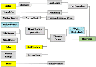 | ||
| Fig. 1 The primary energy sources considered and their routes to hydrogen. Reproduced from ref. 10 with permission from Elsevier, copyright 2005. | ||
To fulfil its role in the future, hydrogen production must meet three key criteria:
i. It needs to follow sustainable routes;
ii. It ought to make use of plentiful and renewable feedstocks;
iii. High-purity hydrogen must be produced, because contaminants are hazardous in most fuel cell and other applications.
Hydrogen may only be regarded as sustainable if both the process's feedstock and the energy source for its electrical input are renewable.28 The options for producing hydrogen sustainably are elaborated in this study. Fuel cells that use hydrogen to produce energy can be employed with ease. Additionally, hydrogen has a high energy yield of 122 kJ g−1, which is 2.75 times higher than fuels derived from hydrocarbons.29 As a technical and policy problem, the use of hydrogen as a fuel for mobile and stationary applications is getting a lot of positive attention.30 The estimated total annual hydrogen consumption for the entire planet is 400–500 billion Nm3.31 The current use of hydrogen accounts for 3% of global energy consumption, with a growth rate of 5–10% each year.32 There are numerous ways to manufacture hydrogen, and Table 2 lists them along with their benefits and drawbacks for producing hydrogen energy.21,24–27 Electricity is used in electrolysis to divide water molecules into hydrogen and oxygen, and the price of electricity is a major factor in the cost of producing H2 energy.21,33,34
| Source | Mechanism | Benefits | Drawbacks | Hydrogen cost ($ per kg) | Efficiency (%) | Ref. |
|---|---|---|---|---|---|---|
| Water electrolysis | 2H2O → 2H2 + O2 | Proven technology | Storage problems | 10–23 | 40–60 | 19 and 20 |
| Zero emission | Applicable only to special purposes | |||||
| Only by-product is O2 | Transportation issues | |||||
| Existing infrastructure already developed | ||||||
| Hydrogen from biomass | Biomass + H2O + Air → H2 + CO2 | Dependent on renewable sources | Inefficient when compared with fossil fuels | 2.05 | 35–50 | 21 |
| Other useful products can be obtained such as adhesives, polymers, fertilizers | Not entirely a clean source because of methane gas produced as a by-product | |||||
| Less expensive | Potential contribution to deforestation | |||||
| Steam methane reforming (SMR) | Biogas + steam → H2 + CO2 | Existing infrastructure. Most developed of these technologies | Unstable supply. Geopolitical tension. Pollution (CO, CO2) | 2.27 | 74–85 | 20 |
| Nuclear energy | C1H2 (synthetic crude) + 2H2O + nuclear heat → CO2 + 3H2 | Less carbon production | Disposal of radioactive waste | 4–7 | 45–50 | 22 |
| Mining and processing of uranium | ||||||
| Potential for accidents | ||||||
| Gasification of coal | C2H4 + O2 → 2CO + 2H2 | Less CO2 emitted than conventional fossil fuel burning | Along with H2, the production of heavy oils, petroleum and coke can occur | 1.48 | 60–75 | 22 and 23 |
| Syngas can be easily collected and used to produce carbon neutral fuels | Large amounts of CO2 are still produced | |||||
| Energy and water intensive |
In Table 3, the environmental effects of the various electrolysis procedures are described together with the current and projected costs of producing hydrogen through electrolysis utilising various electricity sources.34,35Table 3 shows that the most dependable and economically efficient way to currently produce hydrogen is through electrolysis utilising hydropower, although in the future nuclear power may be utilised. Despite being a viable replacement for fossil fuels, hydrogen still faces several difficulties. Due to hydrogen's inability to liquefy at room temperature, these difficulties mostly relate to the high cost of production and the difficulty in storage.16,35,36
| Electricity source | Present cost ($ per kg) | Future cost ($ per kg) | CO2 emission (kg CO2 per kg H2) | Efficiency (%) |
|---|---|---|---|---|
| Hydro | 1.4 | 3–4 | 0 | 25 |
| Wind | 7–11 | 3–4 | 0 | 21 |
| Nuclear | 4.15–7 | 2.45–2.63 | 0 | 45 |
| Solar | 10–30 | 3–4 | 0 | 20 |
Using a strategy based on distinct colours, hydrogen-generating technologies are increasingly being stated.37–39 Grey (or brown/black) hydrogen is created by fossil fuels (mostly coal and natural gas), which results in the release of carbon dioxide.20 Blue hydrogen prevents the majority of the process's greenhouse gas (GHG) emissions by combining grey hydrogen and carbon capture and storage (CCS). Natural gas is converted into blue hydrogen by the steam reforming process. In this process, natural gas is broken down into hydrogen (H2) and carbon dioxide (CO2), with some of the generated CO2 unable to be captured, while the remaining CO2 is captured (85%–95%) and stored underground using commercial CCS techniques. Leakage can still have a harmful impact on ecology and the climate, and the long-term effects of storage are undetermined.40 Solid carbon in the form of carbon nanotubes or filamentous carbon is a by-product of the pyrolysis of methane to produce turquoise hydrogen.41 Green hydrogen is manufactured by electrolysers powered by renewable electricity. It can also be generated via alternative bioenergy-based processes like biomethane reforming or solid biomass gasification.42 Through atomic current electrolysis, purple hydrogen can be produced. Incorporating a hydrogen-producing facility could lessen the need to shut down nuclear power facilities.43 The term “yellow hydrogen” is occasionally used in the literature to refer to purple/pink hydrogen. However, the more typical definition of yellow hydrogen for grid-powered electrolysis is employed. Finally, white hydrogen is hydrogen from its natural form or as a by-product of industrial processes.37
Since its invention in the late 1920s, electrolysis has been used to produce pure hydrogen commercially. In this case, water is separated into hydrogen and oxygen using external electricity. By the 1960s industrialised hydrogen production had switched to options fuelled by fossil fuels, which have continued to be the primary source of energy and raw materials for the manufacture of hydrogen.11 Only 4% of the total hydrogen supply in the world is now produced by electrolysis.44 Numerous hydrogen production techniques, including electrolysis, have been thoroughly researched from an economic, environmental, technological, and social standpoint in the literature.9,27,42,45–58
The electrolyser is the fundamental part of an electrolysis process for producing hydrogen (can be connected either in parallel or in series). The by-product gases, typically hydrogen and oxygen, are often cooled and compressed before being stored for multiple end uses. Since oxygen is typically not a desired result in electrolysis procedures, it is usually immediately released into the environment rather than entering storage. Additionally, the water supply to the electrolyser needs to be adequately treated to remove contaminants and, by extension, any possibility for unintended side reactions. Moreover, due to the absence of moving parts in most electrolysers, routine maintenance is not necessary. The silent operation and modular design of electrolysers make them suitable for distributing an energy supply to residential, commercial, and industrial units. To reduce the costs of electrolyser manufacture, distribution, and installation, considerable technological and material advancements are needed to coincide with efficient function under ambient conditions.13 Different technologies have been compared for their energy efficacy in producing hydrogen (Fig. 2).19
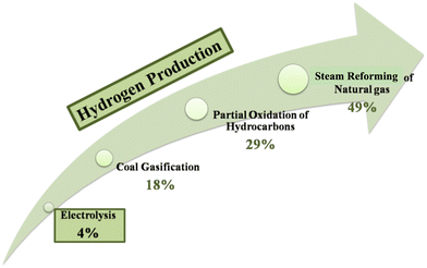 | ||
| Fig. 2 Different methods of hydrogen production. Reproduced from ref. 19 with permission from Elsevier, copyright 2022. | ||
Currently, electrolysis creates pure hydrogen for use in the food, pharmaceutical, electronics, and other industries59–62 and is being studied as a potential technique to create hydrogen for use as a fuel.63 Potentially, electrolysis can offer a clean and sustainable supply of chemical energy when combined with a renewable energy source. In other cases, electrolysis can benefit from off-peak energy to lower the cost of electricity. Two commercial electrolyser technologies are alkaline and solid polymer electrolysers, while alkaline polymer, solid oxide, and molten carbonate are three technologies that are currently being researched and developed.64
Among other operating factors, electrolysers can be categorised based on their operating temperature. The most common systems use polymer electrolyte membrane (PEM) and alkaline technologies in low-temperature electrolysers, sometimes referred to as “water electrolysers”, while molten carbonate electrolysis (MCE) cells and solid oxide electrolysis (SOE) cells are examples of high-temperature electrolysers, also referred to as “steam electrolysers”.65 Due to two primary factors, an increase in the electrolysis temperature is of tremendous interest. Firstly, this is because high-temperature technologies often require less energy than low-temperature ones. In fact, a portion of the electrical energy required to break down the water molecule can be replaced by heat as the temperature rises. Secondly, because of their internal fuel-processing capability, which is improved by higher operating temperatures and the presence of catalysts, they can process hydrocarbon fuels without experiencing severe degradation difficulties. Since losses, including ohmic losses, are reduced at higher temperatures.66 Hydrogen may be produced with very low specific electrical consumption of 3–4 kW h Nm−3 by high-efficiency upgrading of hydrocarbon streams.67
2.1. Electrocatalysts for hydrogen production
Electrocatalysts are required for electrochemical energy conversion and storage techniques in order to create environmentally responsible and long-lasting energy systems. Systems that use electrochemistry for energy conversion and storage often employ a wide variety of electrochemical processes; they generate less carbon dioxide and have high energy densities. The effectiveness and affordability of the electrocatalyst are crucial for its broad application. The use of electrocatalysts increases the electrolysis system's energy efficiency. We selected a few examples to highlight many sorts of electrocatalysts from the many electrocatalyst examples that are accessible. Many compounds based on transition metals have proved to be effective electrocatalysts.9,27,45,55,57,68–95Due to their powerful electrocatalytic activity, transition metal compounds (such as carbide, oxide, sulfide, phosphide, selenide, and others) are among the many electrocatalyst candidates being researched. The workings of different electrocatalysts differ. Because they facilitate the conversion of reaction intermediates and lower resistance, electrocatalysts are essential for increasing reaction speeds. Noble metals are the most complex electrocatalysts for OER (Ir/Ru oxide), HER (Pt), and ORR (Pt), but due to their high cost and scarcity, they are not frequently utilized in industry. Even at relatively low platinum loadings, a number of commercial electrodes constructed from Pt(Mo2C)-produced catalysts exhibit significant catalytic activity for the hydrogen evolution reaction (HER) in 0.5 M sulfuric acid solution.73 Commercial electrodes made of Ni and Ti mesh function well, offer superior cathode materials, and cost less than electrodes made of Pt.74 Other materials offer the best electrode materials for general application since they are less expensive than Pt-based electrodes and have good performance. Of course, the cost of the electrodes must come next. They can be made of costly and affordable materials, corrosion-resistant metals, and alloys, including noble metals.
The components used for manufacturing the electrodes used in water in general, but particularly in seawater electrolysis, must adhere to precise specifications. Both the most extensively researched hydrogen evolution reaction (HER) and the less well-known oxygen evolution reaction (OER) must occur at the electrodes in seawater, hence the electrodes must have electrocatalytic qualities. On the electrolysis cell, this will lessen polarizations and explicit voltage losses. The findings of investigations on appropriate seawater electrocatalysts for HER recently employed in the electrolysis process are shown in Table 4.
3. Water electrolysis
This approach makes reference to the earliest technique for creating hydrogen, which dates to the 19th century.101 Although abundant, renewable energy is sometimes unreliable and intermittent. The need to store energy for times when the sun is not beaming and the wind is not blowing will increase as our reliance on renewable energy increases.102 Utilising renewable energy (as and when it becomes available) to split water into hydrogen and oxygen in accordance with eqn (1) is one of the more interesting methods for storing this energy.103A carbon-neutral fuel production and consumption cycle can be created by storing the hydrogen created by the reaction in eqn (1) and then oxidising it (by burning in air or in a fuel cell) to release energy and regenerate water. The overall reaction is shown below:
| H2O + electricity → H2 + ½O2 | (1) |
At room temperature and pressure, the reaction in eqn (1) is a thermodynamically upstream process and needs an energy input of 286 kJ mol−1. This conversion is thought to be best accomplished via electrochemical methods, which just need inputs of water and voltage to make hydrogen.104 According to eqn (2), water is oxidised at the anode when the environment is acidic.
| 2H2O → O2 + 4e− + 4H+ | (2) |
These protons cross into the cathode compartment (to complete the electrochemical circuit), and the electrons move through the external circuit. The hydrogen evolution reaction (HER), which combines the protons and electrons at the cathode, follows:
| 4e− + 4H+ → 2H2 | (3) |
The minimal theoretical voltage needed to drive the OER and HER (to split water) is 1.23 V at ambient temperature. The reactions must have additional energy, or activation energy, in order to occur at noteworthy rates. The amount of activation energy required increases with the rate of water splitting (measured as charge flowing per unit area of electrode per unit time, or “current density”). The necessity for potential bias above the 1.23 V minimum results from the increased energy. The finest electrocatalysts for acidic environments (where protons serve as the electrochemical charge carriers, as shown in the figure below) are precious metals (platinum at the cathode and IrO2 or RuO2 at the anode). First-row transition metals (and their alloys) and oxides provide effective HER and OER catalysts, respectively, when the HER and OER proceed under the basic conditions stated in the equations below.104
| Basic HER: 4H2O + 4e− → 2H2 + 4OH− | (4) |
| Basic OER: 4OH− → O2 + 2H2O + 4e− | (5) |
The oxygen evolution reaction (OER) and hydrogen evolution reaction (HER) are the two main processes that make up overall water electrolysis. Both of these reactions require effective electrocatalysts105–107 to speed up their slow kinetics for high energy efficiency.104,108–110 Transition metal-based electrocatalysts play an important role in clean energy.111,112 The development of non-precious OER/HER electrocatalysts as substitutes for Pt/C and Ir/Ru-based catalysts has made significant progress in recent years.113,114Fig. 3 depicts a typical electrolysis cell for splitting water.
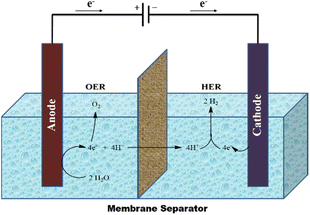 | ||
| Fig. 3 Electrolysis cell for splitting water. Reproduced from ref. 104 with permission from Nature Publishing Group UK London, copyright 2017. | ||
About 1 × 10⁻⁶ S m−1 is the electrical conductivity of pure water, making it a poor conductor of electric currents. Under these conditions, hydrogen and oxygen production would require very high voltages. To make water more conductive, salts, acids, or bases are typically added. Acidic and alkaline solutions have higher electrical conductivities than neutral solutions because hydrogen ions (H+) and hydroxyl ions (HO−) have a greater degree of mobility in these environments. Despite the fact that acidic solutions are more conductive than alkaline solutions, the corrosion of steel-based metallic components leads to a rise in the material consumption of the electrodes, which results in process losses. Due to the formation of carbonates under the effect of carbon dioxide in the air, which results in a 75% reduction in initial conductivity, the electrical conductivity of alkaline electrolytes diminishes with time.9
As a sustainable approach, water electrolysis technology has been developed to produce high-purity hydrogen, called green hydrogen. A voltage is applied to the cells during water electrolysis, and a DC current travels between two electrodes while in contact with an ionic conducting medium, producing hydrogen and oxygen from the breakdown of water (Fig. 4).20
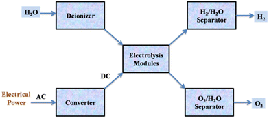 | ||
| Fig. 4 Flow diagram of the water electrolysis process. Reproduced from ref. 20 with permission from Elsevier, copyright 2017. | ||
The best way for splitting water is electrolysis, which is a robust and well-understood process.20 However, because of how endothermic the process is, electricity is used to supply the needed energy input.115 In practice, the electrolysis of water achieves an energetic efficiency of 50–70% (chemical energy obtained per electrical energy provided).4
Since high-purity water supplies are necessary for all commercially available water electrolysers, a low system efficiency of 70% and high cost limit the applicability of water electrolysis.116–118 In many places, especially in hot, arid locations, freshwater has historically been a rare resource. Equipment for water purification and desalination is required while building an electrolytic water system in order to pre-treat saline and low-grade water.119,120 The flow of input-fluid and outflow-air streams, gas regulators, and thermal management devices are all complicated setups that distinguish practical electrolysers from basic laboratory systems. Even before factoring in related investments in transportation and maintenance, the deployment of more water purification devices will eventually come at a prohibitive cost. Direct use of saline seawater in water electrolysis systems can be a feasible and practical strategy for coastal dry zones and offshore large-scale hydrogen outputs when cost reduction is taken into account. The economic efficiency of purification/desalination can be significantly increased by removing pre-treatment systems. For the electrolysis of water and seawater to produce hydrogen, solar energy, geothermal energy, wind, micro-hydropower, and wave energy are all appropriate sources of energy (Fig. 5).
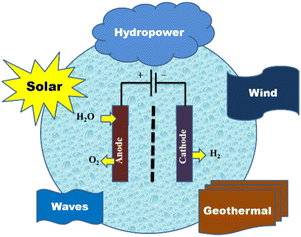 | ||
| Fig. 5 Renewable sources of energy for hydrogen production from seawater electrolysis. Reproduced from ref. 9 with permission from MDPI, copyright 2022. | ||
The market for hybrid renewable energy systems has grown significantly as a result of the year-round fluctuations in the availability of renewable energy sources like solar, wind, small hydro, geothermal, and ocean power. Numerous studies on the architecture, operation, dependability, and optimisation of hybrid renewable energy have been published recently in response to the rise in demand. The key renewable energy sources listed in Table 5 can be used to electrolyse seawater in a sustainable manner.49,75,119–142
Alkaline water electrolysis, proton exchange membrane (PEM) water electrolysis, and solid oxide water electrolysis (SOEC) can produce hydrogen when different electrolytes are used.143 Key features of these techniques are described in Table 6.
| Features | Alkaline | AEM | PEM | Solid oxide |
|---|---|---|---|---|
| Anode reaction | 2OH− → H2O + ½O2 + 2e− | 2OH− → H2O + ½O2 + 2e− | H2O → 2H+ + ½O2 + 2e− | O2− → ½O2 + 2e− |
| Cathode reaction | 2H2O + 2e− → H2 + 2OH− | 2H2O + 2e− → H2 + 2OH− | 2H+ + 2e− → H2 | H2O + 2e− → H2 + O2− |
| Overall cell | H2O → H2 + ½O2 | H2O → H2 + ½O2 | H2O → H2 + ½O2 | H2O → H2 + ½O2 |
| Operating temperature | 70–90 °C | 60–40 °C | 50–80 °C | 700–850 °C |
| Efficiency | 50–78% | 57–59% | 50–83% | 89% (laboratory) |
| Electrolyte | Electrolyte KOH/NaOH (5 M) | DVB polymer support with 1 M KOH/NaOH | Solid polymer electrolyte (PFSA) | Yttria-stabilized Zirconia (YSZ) |
| Electrode/catalyst (hydrogen side) | Nickel-coated perforated stainless steel | Nickel | Iridium oxide | Ni/YSZ |
| Electrode/catalyst (oxygen side) | Nickel-coated perforated stainless steel | Nickel or nickel alloys (NiFeCo) | Platinum carbon | Perovskites (LSCF, LSM) (La,Sr,Co,FE) (La,Sr,Mn) |
| Cell pressure | <30 bar | <35 bar | <70 bar | 1 bar |
| Separator | Asbestos/Zirfon/Ni | Fumatech | Nafion® | Solid electrolyte YSZ |
| Electrode area | 10![[thin space (1/6-em)]](https://www.rsc.org/images/entities/char_2009.gif) 000–30 000–30![[thin space (1/6-em)]](https://www.rsc.org/images/entities/char_2009.gif) 000 cm2 000 cm2 |
<300 cm2 | 1500 cm2 | 200 cm2 |
| Lifetime (stack) | 60![[thin space (1/6-em)]](https://www.rsc.org/images/entities/char_2009.gif) 000 h 000 h |
>30![[thin space (1/6-em)]](https://www.rsc.org/images/entities/char_2009.gif) 000 h 000 h |
50![[thin space (1/6-em)]](https://www.rsc.org/images/entities/char_2009.gif) 000–80 000–80![[thin space (1/6-em)]](https://www.rsc.org/images/entities/char_2009.gif) 000 h 000 h |
20![[thin space (1/6-em)]](https://www.rsc.org/images/entities/char_2009.gif) 000 h 000 h |
| Gas diffusion layer | Nickel mesh | Nickel foam/carbon cloth | Titanium mesh/carbon cloth | Nickel mesh/foam |
| Capital costs (stack) minimum 1 MW | US $270 per kW | Unknown | US $400 per kW | >US $2000 per kW |
| Capital costs (stack) minimum 10 MW | US $500–1000 per kW | Unknown | US $700–1400 per kW | Unknown |
| Bipolar plates | Stainless steel/nickel-coated stainless steel | Stainless steel/nickel-coated stainless steel | Platinum/gold-coated titanium or titanium | Cobalt-coated stainless steel |
| H2 purity | 99.5–99.9998% | 99.9–99.9999% | 99.9–99.9999% | 99.9% |
| Development status | Mature | R & D | Commercialised | R&D |
| Nominal current density | 0.2–0.8 A cm−2 | 0.2–2 A cm−2 | 1–2 A cm−2 | 0.3–1 A cm−2 |
| Voltage range (limits) | 1.4–3 V | 1.4–2.0 V | 1.4–2.5 V | 1.0–1.5 V |
3.1. High-temperature water electrolysis
This type of water electrolysis consists of following types:| H2O + CO2 + 2e− → CO32− + H2 | (6) |
| 2CO2 + 2e− → CO32− + CO | (7) |
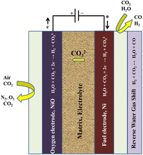 | ||
| Fig. 6 Working principle of a molten carbonate electrolysis (MCE) cell. Reproduced from ref. 156 with permission from Elsevier, copyright 2018. | ||
In reaction (6) steam is electrolysed in an MCE, while in reaction (7) carbon dioxide undergoes an electrochemical reaction to form carbon monoxide. The latter is slower and is not predicted to happen in the hydrogen electrode, according to literature reports.157 It is anticipated that carbon monoxide will be produced through an equilibrium shift because of the operating temperature and the presence of nickel catalyst in the fuel electrode. Since steam and carbon dioxide are the only accessible reactants in this situation, the reaction is known as the reverse water–gas shift. The local condition indicates that all species are present and the reaction has reached thermodynamic equilibrium. The following is the reaction:
| CO2 + H2 ↔ H2O + CO | (8) |
| CO32− → CO2 + ½O2 + 2e− | (9) |
As an intake reactant, oxygen gas is not needed. Carbon dioxide and oxygen are produced via the OER. The entire reaction between the two electrodes is the breakdown of water into hydrogen and oxygen:
| H2O → H2 + ½O2 | (10) |
Carbon dioxide moves from the hydrogen electrode to the oxygen electrode during the procedure. This indicates that both CO2 and steam must be supplied to the electrode. A MCEC differs from a conventional electrolyser in that carbon dioxide is supplied to the hydrogen electrode and produced at the oxygen electrode. The hydrogen electrode contains carbon dioxide, which causes a chemical or electrochemical reaction that also produces carbon monoxide.158
In addition to transporting the carbonate ions between the electrodes and separating the fuel and oxidant gases, the electrolyte is retained in a porous matrix, typically constructed of γ-LiAlO2.67 However, because carbon dioxide is involved and the product stream from the electrolyser contains both hydrogen and carbon dioxide, there is a significant practical issue with the operation of an MCE cell, necessitating gas separation for the production of pure hydrogen and recycling of carbon dioxide to the cell. In order to produce syngas (a combination of CO and H2) through co-electrolysis of water and carbon dioxide, the MCE cell is probably a more advantageous alternative.64
One of the primary objectives of present scientific research is the investigation of novel technical methods to reduce CO2 emission output into the atmosphere. The performance of MCECs for both H2 production and CO2 capture has been examined. Due to the combination of the steam reforming reaction, which can be supported inside the cell, and subsequent electrolysis, MCECs can work with CH4 and H2O feeding, enabling the syngas or hydrogen production. In this case, MCECs can function as a single, independent system for the generation of hydrogen as well as being retrofitted with reformer units to extend the scope of reforming, allowing for higher CH4 conversion, production of H2, and simultaneous storage of CO2.159
Recently, SOE cells have proved highly efficient for conversion of water and carbon dioxide to produce carbon fuel and hydrogen, with a high temperature necessary for their conversion and storage.19 SOEs are divided into two groups in the literature: H+ SOE and O2− SOE. O2− SOE is currently in the demonstration phase, whereas H+ SOE is at the lab scale.161 A dense electrolyte serves as the ionic conductor in SOECs, such as the oxygen ion-conducting SOEC (O-SOEC) and the proton-conducting SOEC (H-SOEC), in which reaction gases such as H2O or CO2 are fed into the cathode (or anode) and oxide ions (or protons) are conducted across the dense electrolyte to the cathode (or anode). The evolution of oxygen at the anode enables the cathode to produce fuel gases.162 This method is very useful for obtaining these gases but requires a high production cost (80% of the energy comes from electricity).163 Some technical issues are also involved because of the high temperature, such as leakage of gas-tight components, the requirement of tough materials and its limited application. Moreover, this method has high operational and maintenance costs. Different technological approaches may enhance durability and electro-catalytic performance under low temperature. In renewable energy conversion and storage systems SOE cells have been proved to be a useful and successful technology.162 The working principle of an SOE cell is shown in Fig. 7.162
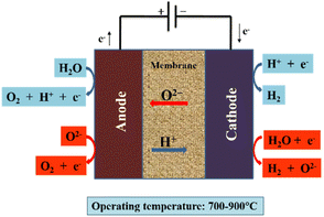 | ||
| Fig. 7 Schematic of SOEC (O/H-SOEC). Red arrows represent the O-SOEC, and blue arrows represent the H-SOEC. Reproduced from ref. 162 with permission from Springer, copyright 2021. | ||
The endothermic reaction occurs in the SOE cell, while the oxidation reaction occurs at the anode, where oxygen ions move through the electrolyte.
| Anode: O2− → ½O2 + 2e− | (11) |
| Cathode: H2O + 2e− → O2− + H2 | (12) |
3.2. Low-temperature water electrolysis
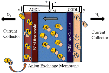
This type of electrolysis includes following methods:This type of electrolysis is operated between 30 and 80 °C with a concentrated alkaline solution of sodium hydroxide. Moreover, membranes with nickel-catalysed stainless steel and zirconium dioxide are used as a separator. Furthermore, there are various challenges associated with this system due to the use of corrosive electrolytes and medium mobility of the hydroxide ions. Due to salt formation of potassium carbonate and sensitivity of electrolyte, decreased ionic conductivity and hydroxyl ions is prominent. Therefore, alkaline water electrolysis produces lower purity hydrogen and oxygen gases since the membrane does not completely stop gases crossing over from one half of the cell to the other. Generally, the technique consists of two half-cell reactions, with oxygen evolution at the anode and hydrogen evolution at the cathode.19
| Anode: 2OH− → ½O2 + H2O + 2e− | (13) |
| Cathode: 2H2O + 2e− → 2OH− + H2 | (14) |
Gas bubbles containing oxygen and hydrogen, respectively, are created on the surfaces of the cathode and anode during the reaction. When the bubbles reach a particular size, they separate off the surface.170 Several unfavourable events occur in the electrolysis system as a result of the creation of a gas phase. Gas bubbles cover the electrode surface, preventing the flow of electrons from the electrode to the electrolyte. The electrode surface is harmed and the electrolyte's resistance is increased by bubbles.170,171
The low maximum power density attained with liquid electrolytes is an issue with alkaline electrolysis. This restriction results from the detrimental impact of bubble formation. It is necessary to modify and improve materials and configurations since bubble generation in electrolysis cells is unavoidable. Numerous strategies have been used to counteract these consequences. Although they result in a more complicated system configuration, the use of centrifugal fields, magnetic fields, super gravity fields, ultrasound, and microwave treatments do not considerably increase efficiency. The application of an AEM and a zero-gap configuration, respectively, is a very promising technique to enhance the performance of the electrolysis cells. Additionally, operation with an AEM would prevent extra harmful effects of liquid electrolytes.171 The working principle for an alkaline electrolysis cell is shown in Fig. 8.170
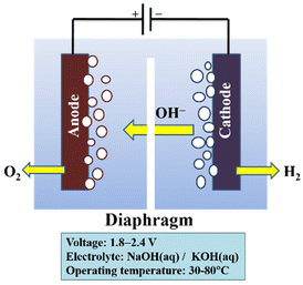 | ||
| Fig. 8 Diagram of an alkaline electrolysis cell. Modified from ref. 170 with permission from Elsevier, copyright 2010. | ||
In-depth research has been conducted on numerous novel processes, and some of them have already achieved high efficiency. Anion-conducting membrane alkaline water electrolysers have a number of advantages over alternative technologies. One of the key benefits of alkaline systems over electrolysers utilising proton-conducting electrolytes is the relatively inexpensive cost of the electrode materials because less expensive, non-noble metals are stable in alkaline media.28
However, because of the modest OH− mobility and use of corrosive (KOH) electrolytes, alkaline water electrolysis faces the major difficulty of limited current densities (0.1–0.5 A cm−2).172 To reduce gas crossing, commercial alkaline water electrolysers frequently employ 2–3 mm-thick porous layers.173 Device performance is affected by limited ion transport through the layer. Numerous researchers in the past have attempted to create “zero gap” electrolysers, in which a 50–100 mm-thick anion exchange membrane is used in place of the 2–3 mm-thick porous layer.28,173–177
Some advancements are still needed to improve this technology to reduce the cross-over of gases and increase current density. Separators and electrode material need to be developed to achieve these challenges, while solar and wind energy sources will be most beneficial for cost reduction. One such avenue recently developed for water splitting is two-dimensional metal organic frameworks of nickel nano flakes in alkaline media.178 Some research organisations/institutes are still actively working in this field to improve efficiency and lower the cost of hydrogen production.179
Alkaline water electrolysis mostly takes place by using a Ni-based electrolyte and 5 M KOH which reduces resistance between porous transport and catalyst layers. Current density should also be increased by ca. 2–3 A cm−2 using thinner separators with a high surface area of electrode material. For large-scale applications, the alkaline water electrolysis is a good system design. Alkaline water electrolysis now costs between $500 and $1000 per kW, and the system lasts for 90![[thin space (1/6-em)]](https://www.rsc.org/images/entities/char_2009.gif) 000 h.143,180
000 h.143,180
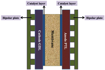 | ||
| Fig. 9 Core components of a PEM electrolyser cell; PTL = porous transport layer; GDL = gas diffusion layer. Modified from ref. 185 with permission from IOP Publishing, copyright 2021. | ||
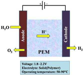
In PEM water electrolysis, catalysts based on Pt/Pd are typically used as the cathode for the hydrogen evolution reaction (HER) and catalysts based on RuO2/IrO2 are typically used as the anode for the oxygen evolution reaction (OER).186–189 An acidic membrane in the form of a solid electrolyte (Nafion, DuPont) and anode and cathode catalysts (mostly Ir and Pt, respectively) make up a PEM electrolyser.190 The membrane separates the hydrogen and oxygen gases produced by the subsequent reaction while allowing the H+ ions to pass from the anode to the cathode.42
| Anode: H2O → ½O2 + 2H+ + 2e− | (15) |
| Cathode: 2H+ + 2e− → H2 | (16) |
At the anode, hydrogen molecules break apart, which ionises the atoms and sends their electrons into an external circuit; through an ion-exchange membrane protons congregate at the cathode. Oxygen, protons from the ion-exchange membrane, and electrons all then come together to afford water or steam. We can get an energy conversion efficiency of 60% or more with this method.191,192 The working principle of the PEM electrolysis cell is shown in Fig. 10.
Membrane electrode assemblies (MEAs), current collectors (gas diffusion layers), and separator plates make up the majority of the parts of a PEM water electrolysis cell. Fig. 11 depicts a typical overall view of a PEM water electrolysis cell assembly. However, MEA, which divides the cell into two half cells (anode and cathode), is at the centre of the electrolysis cell.181
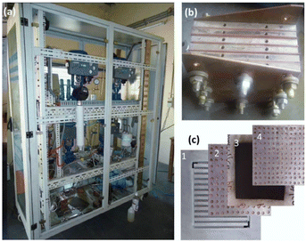 | ||
| Fig. 11 (a) Overview of typical PEM water electrolyser, (b) PEM cell stack and, (c) cell components; 1-bipolar plate, 2-anode current collector, 3-MEA, 4-cathode current collector.181 | ||
These proton exchange membranes offer a number of benefits, including low gas permeability, robust proton conductivity (0.1 ± 0.02 S cm−1), reduced thickness (20–300 μm), and high-pressure operation. PEM water electrolysis is one of the preferable technologies for converting renewable energy to highly pure hydrogen from a sustainability and environmental perspective. Other excellent attributes offered by the PEM water electrolysis method are a small carbon footprint, high current densities (over 2 A cm−2), lower operating temperatures (20–80 °C), ultrapure hydrogen production, and the production of oxygen as the by-product.20,27,193–195 The purity of the gases produced is higher than that of alkaline electrolysis.42 As a result, when compared with alkaline electrolysis, PEM electrolysis can achieve great efficiencies (50–75%) with a quick response.17
The PEM electrolyser is expected to cost between $1000 and $1400 per kW, with clear paths to be reduced to $400. The $1 per kg H2 target set forward in the US Department of Energy's Hydrogen Energy Earth Shot campaign must be reached in order to reach its ultimate goal of $150 per kW. Due to the acidic nature of the electrolyte with strong proton conductivity and the structures that reduce ohmic losses, the water electrolysis kinetics in PEM cells is faster than in alkaline electrolysis. The capability of applying a high pressure on the cathode side while operating the side of the anode at atmospheric pressure is a beneficial aspect of PEM electrolysis.185
However, cost and durability continue to be obstacles preventing PEM electrolysers from being widely used. To research the deterioration of PEM electrolysers and further increase their durability, collaborative accelerated stress tests across many laboratories are extremely desirable.185 The usage of expensive polymeric membranes and the need for noble metals due to the electrolyser's acidic liquid are current drawbacks. One of the main difficulties is reducing the amount of noble metals used in PEM electrolysers.181 The adoption of platinum group metals as noble metal catalysts, Nafion-based membranes, and Ti-based stack materials are causes of PEM water electrolysis expenditure issues.42
AEM electrolysis is projected to outperform conventional electrolysis technologies in terms of performance and total cost.202 Previous research with AEM electrolysis has yielded promising outcomes. One study found that a membrane electrode assembly (MEA) combination of polybenzimidazole (PBI) AEM and specific catalysts (Ni–Fe–Ox for oxygen evolution and Ni–Fe–Co for hydrogen evolution) performed best under specific conditions, with an AEM electrolysis efficiency of 74% at 1000 mA cm2, 1.9 V, and 60 °C.203
Despite its satisfactory performance, the AEM electrolyser's performance is lower than that of traditional PEM electrolysers.198,199 In AEM electrolysers, the voltage drives the electrolysis reaction, whilst the current reflects the rate of hydrogen generation. When a voltage is supplied between the anode and cathode, electrons travel via an external circuit and are balanced by the movement of hydroxide ions through the AEM.204 The hydroxide ions strive to cross the AEM when more voltage is applied, while the electrons will travel via the external circuit. However, at lower voltages, electrons and OH− cannot transfer due to internal barriers.205
A drop in voltage causes a decrease in hydrogen production, termed charge transfer resistance or activation overpotential. And if the applied voltage is low, the flow of electrons is restricted by internal components such as the catalyst layer, AEM, and gas diffusion electrode (GDL). The ohmic resistance (Rohm) is the name given to this constraint.206 However, the performance of an AEM electrolyser is determined by three variables: kinetic resistance, ohmic resistance, and mass transfer resistance.207,208
3.3. Solar-powered water electrolysis
Renewable energy electrolysis would produce an exceptionally clean hydrogen cycle (Fig. 13). Solar (and wind)-generated hydrogen could meet the world's anticipated energy needs; however, delivering it may cost more than making hydrogen from natural gas.209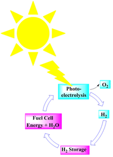 | ||
| Fig. 13 A renewable hydrogen cycle. Modified from ref. 209 with permission from Elsevier, copyright 2002. | ||
Solar-powered water-splitting for hydrogen production is a clean and viable energy solution; two promising technologies for this are photovoltaic-electrocatalysis (PV-EC) and photoelectrocatalysis (PEC). A photoelectrode harvests light and electrolyses water in the PEC process. PV-EC incorporates separate modules for solar-powered electricity generation and water splitting (Fig. 14), distinguishing PV-EC from a standard PEC configuration.121
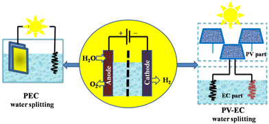 | ||
| Fig. 14 Two pathways for solar hydrogen production by PEC and PV-EC water splitting. Modified from ref. 121 with permission from Springer, copyright 2021. | ||
It is generally agreed that Brattain, Garret,211 and Gerischer's212 research established the groundwork for contemporary photoelectrochemistry. Numerous articles on photoelectrochemical cells emerged in the wake of the 1973 oil crisis, which prompted an increase of new study into renewable energy sources.213 The focus was on two types of cells: regenerative cells and photosynthetic cells. Light is converted to electric power by regenerative cells without generating any net chemical change. Photon-generated electron–hole pairs are separated, with negative charge carriers passing through the semiconductor to the current collector and external circuit and positive holes being collected by a redox relaying molecule. Water is oxidised to oxygen at the semiconductor photoanode and reduced to hydrogen at the cathode in photosynthetic cells, which work similarly but include two redox systems, as shown in Fig. 15a.212
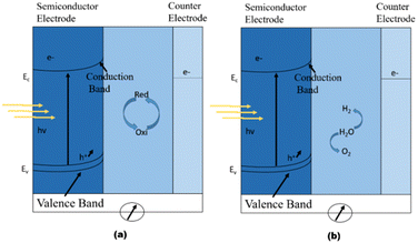 | ||
| Fig. 15 Working principle of photoelectrochemical cells. (a) Regenerative-type cell producing electric current from sunlight; (b) a cell that generates a chemical fuel, hydrogen, through the photo-cleavage of water. Reproduced form ref. 212 with permission from Nature Publishing Group UK London, copyright 2001. | ||
After the 1972 Nature paper by Fujishima and Honda showing photodriven water oxidation on TiO2 with a small bias, the idea of a single-material PEC cell that could drive both photooxidation and photoreduction of water without an external bias was developed.214 A single substance is immersed in water to make hydrogen and oxygen, making this idea interesting. However, there are several prerequisites, such as the material requiring a large band gap to generate energy but not one that is too large to absorb sunlight. Band edges must align with exact energy levels to enable water oxidation and reduction processes (Fig. 15b). The material should be able to separate and transport light-generated charge carriers without recombination. The interface of the material should also be catalytically active for water oxidation and reduction, as well as stable in water and light. The material should also be non-toxic and affordable.
Substantial effort has been put into discovering a suitable material for efficient PEC water-splitting.215–217 Hundreds of compounds were investigated using combinatorial methods.218–220 All requirements, however, have not been met by any material. Using a plethora of materials to create a PEC device is more efficient since the stresses on each material are reduced. Instead of relying on each element to be efficient at everything, synergy of the materials can accomplish what is required. Putting distinct functionalities into a variety of materials has been beneficial for the development of useful technologies.
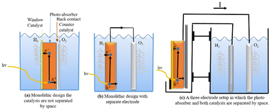
Different approaches to monolithic device design incorporating many materials are studied in the research literature. One way to do this is to make a group of monoliths that are suspended as nanoparticles.217,221,222 This method is appealing because it is simple, and there is no need for wires, wiring, or separating the cells. It can also be made with sol–gel synthesis methods, which can be used on the large scale and possibly be less expensive.223 Small particles are used in diffusion to split and move charges. Co-catalysts increase the activity of surface catalysts; two co-catalysts can be used; however, this increases the difficulty. This design makes oxygen and hydrogen at the same time, which raises worries about back reactions and so induces the additional requirement of gas separation in another second step. Because the particles are so small, it is hard to tell which ones do what. This limits the materials that can be used, but not as much as with single-material monoliths. Fig. 16c shows a monolithic cell with multiple layers. Pure PEC cells, underground PV junctions, and PV-electrolysis can employ this type of design. This design is larger than the nanoparticles-in-suspension approach, making material selection and combination easier. This design has yielded multiple functioning devices, including the 2.5% efficient “artificial leaf” and a 10% efficient CIGS (thin-film solar cell) device.224
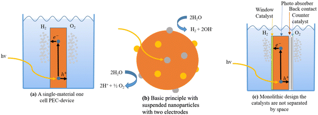 | ||
| Fig. 16 (a) A single-material one-cell PEC-device. (b) Basic principle with suspended nanoparticles with two electrodes. (c) Monolithic design where the catalysts are not separated in space. | ||
Separating the cathode and anode spatially changes the perspective from a multi-layered PEC cell. Instead of passing through a back contact to a second electrode, the majority of carriers can be wired to the counter electrode; the only difference is charge distance. This method uses a macroscopic wire and a resistive element. The main benefit is greater freedom in geometrical arrangements, synthesis techniques, and material choice. This topological transition lets electrodes be developed, manufactured, and studied separately in an attempt to boost device performance.
There are numerous designs of this concept. One involves a photoactive electrode and a counter electrode performing a sole catalytic function, which constitutes the simplest configuration (Fig. 16a). Either a p-type semiconductor photocathode or an n-type semiconductor photoanode, as in Fig. 16a, can serve as the photoactive electrode. The devices produced by Khaselev et al.225,226 and Recee et al.227 show that the single photoactive electrode can be configured as a tandem cell. Fig. 16b illustrates a more sophisticated technique that employs two photoactive electrodes to create a spatially separated tandem cell. For instance, Abdi et al.228 constructed a 4.9% efficient device using BiVO4 and a tandem junction a-Si solar cell, while Brillet et al.226 presented a 3.1% efficient device using WO3 and a dye-sensitised solar cell as examples.
Researchers may improve each step and look into the fundamental functioning of the system by looking at the two half-reactions separately. Through photocurrents, the macroscopic charge transport makes it simple to gauge efficiency. Once the materials for both half-reactions have been determined as being effective, they can be joined to form a device for the full reaction. In the literature, a number of substances have been investigated for their potential to act as catalysts in these half-reactions.215–217
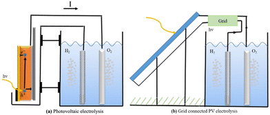
PV-electrolysis is technologically mature because the PV (photovoltaic) part and the catalysts can be developed, improved, and tested separately. They can be connected directly, as shown in Fig. 18a, or through the power grid, as shown in Fig. 18b.
The transmission efficiency of electricity across power lines is approximately 93%, with loss of 7%.229 Hydrogen electrolysers often make use of expensive resources and run at high levels to maximise efficiency and minimise costs. Unfortunately, this causes a loss of efficiency. However, other types of electrolysers can be even more efficient than alkaline ones. The biggest problem with these systems is the price, not how well they work. Creating hydrogen from natural gas is less expensive than using solar cells, but that could change in the future. Then, attention will turn to improving the process's catalysts.
Directly connecting the solar cell to the electrolysers, rather than going through the grid, avoids the need for inverters and decreases grid losses. Since this lowers solar cell and electrolyser prices, it can make the system more competitive in the market. But there is a disadvantage: since the electrolyser's power supply is less stable, its efficiency may suffer as a result. The benefit of disconnecting from the grid and inverters can be nullified if this happens.230
3.4. Grid-connected water electrolysis
Grid electrolysis involves connecting the electrolyser to an existing electrical network. For the transition to a prosperous hydrogen economy, this approach appears to be the shortest and least expensive. However, using this technique, hydrogen production is not practicable in isolated or rural areas lacking access to dependable electricity. Additionally, even though electrolysis does not directly release any harmful gases to the environment, it indirectly harms the environment by increasing the combustion of fossil fuels to produce electricity. Much research effort has focused on various elements of grid electrolysis, such as energy storage and grid balancing.231 Currently, it is believed that the most practical method for producing hydrogen for the switch to vehicles powered by hydrogen is grid electrolysis (e.g., fuel cell vehicles).232,233 There is more information available on grid electrolysis and its potential for producing sustainable hydrogen elsewhere.234–236Various variables, such as the capital expenditure for controlling peak demands, the investments required for grid reliability, and the integration of renewable energy sources, might be linked to the rising interest in energy storage for the grid. There is acknowledgment that battery systems can offer a variety of high-value options, assuming that reduced costs can be reached, even if pumped hydropower is currently the dominant form of energy storage. The battery systems including redox-flow batteries, which are inexpensive, lithium-ion batteries, developed for commercial gadgets and electric vehicles, and sodium–sulfur batteries, which are commercially accessible for grid applications.102
Several electrolyser stacks, compressors, and gaseous hydrogen storage units make up a large-scale water electrolysis hydrogen production system (Fig. 19). We take into account hydrogen production from electrical grids with strong renewable energy penetration and usage in a variety of applications across various industries. This system layout was primarily chosen based on the input needs of feedstock hydrogen in the subsequent chemical processes related to the production of hydrocarbon fuels, industrial use, or fuel supplied in the production of electricity. A developed hydrogen value chain is necessary for centralised electrolytic hydrogen production, which is also applicable to the transportation industry. More significantly, the integration of renewable energy sources into the power grid through the use of water electrolysis and the production of hydrocarbon fuel (synfuel) creates a process that can decarbonize the energy supply chain. By turning electricity into hydrogen, the inclusion of large-scale water electrolysis into the power grid might reduce the volatility of renewable energy sources. The installed capacity of the water electrolysis facility is anticipated to vary from several MW to 100 MW, or possibly GW, for the case of synfuel production on a massive scale.233
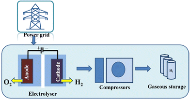 | ||
| Fig. 19 The water electrolysis technique for producing hydrogen (grid electrolysis process). Reproduced from ref. 233 with permission from Elsevier, copyright 2019. | ||
The key distinction from typical chemical processes, such as Steam Methane Reforming (SMR), is the use of water and electricity rather than coal or natural gas (NG) in an electrolyser that is connected to the grid to generate hydrogen. Additional sources of electricity include 26 MW and 54 MW solar and wind farms, respectively. The following possibilities are listed:
✓ An electrolyser that is grid-connected receives power from the exterior public electrical grid;
✓ Wind turbine (WT)/grid-connected electrolyser: The grid and wind turbine both provide energy to the electrolyser. A portion of the electricity generated by the WT is marketed to the electricity market because the wind turbine is greater than the electrolyser capacity;
✓ Photovoltaic (PV)/wind turbine (WT)/grid-connected electrolyser: The grid-connected electrolyser is powered by PV and WT, and some of the electricity is sold to the electricity market;
✓ PV/grid-connected electrolyser: The grid and PV work together to supply energy to the electrolyser. A portion of the electricity generated by PV is distributed to the electrical market since the PV capacity is greater than the electrolyser capacity.237
To create the techno-economic model for a grid-connected large-scale hydrogen production plant, three possibilities are taken into account (as illustrated in Fig. 20). This model also takes different power price structures, hydrogen generation and storage systems, and component sizes into account.
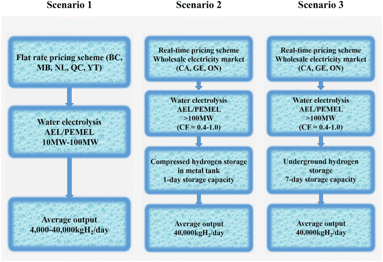 | ||
| Fig. 20 Deployment scenarios for water electrolysis. (BC = British Columbia; MB = Manitoba; NL = Newfoundland and Labrador; ON = Ontario; QC = Quebec; YT = Yukon; CA = California; GE = Germany.) Modified from ref. 233 with permission from Elsevier, copyright 2019. | ||
✓ In scenario 1, when electricity costs are defined as fixed-charge rates, the impact on a levelized cost of hydrogen is examined. Since the operation schedule reflects the output demand, hydrogen storage is not taken into consideration. For medium-scale implementation, the average outputs are set at 4000 kgH2 per day, and for large-scale deployment, at 40![[thin space (1/6-em)]](https://www.rsc.org/images/entities/char_2009.gif) 000 kgH2 per day.
000 kgH2 per day.
✓ In scenario 2, a metal tank at 200 bar is used to examine the impact on a levelized cost of hydrogen at wholesale energy markets with a 1-day storage capacity. The storage capacity (40![[thin space (1/6-em)]](https://www.rsc.org/images/entities/char_2009.gif) 000 kgH2) is viewed as being sufficient for one day. From 0.4 to 1.0 capacity factors are taken into account. The adaptability of areas where large-scale geological hydrogen storage is not practical is taken advantage of by this system arrangement.
000 kgH2) is viewed as being sufficient for one day. From 0.4 to 1.0 capacity factors are taken into account. The adaptability of areas where large-scale geological hydrogen storage is not practical is taken advantage of by this system arrangement.
✓ Scenario 3 investigates the impact of massive underground hydrogen storage on a levelized cost of hydrogen at wholesale energy markets. The production facilities anticipate that taking into account a 7-day storage capacity will allow them to further benefit from cost savings during non-peak times. The capacity factor is rated from 0.4 to 1.0, just like in scenario 2.233
3.5. Wind-powered water electrolysis
In wind electrolysis, the electrolyser is connected to the power generated by wind turbines. It is possible to create cleaner hydrogen using wind electrolysis, which also holds the potential to make greater use of the renewable energy sources that are already present in the area238 and to increase the proportion of renewable energy in the electric grid while lowering greenhouse gas emissions.239 However, hydrogen generation from wind electrolysis needs to be competitively priced to allow for a higher uptake of renewable energy sources, e.g. to compete with gasoline or other vehicle fuels as a vehicle fuel or be cost-competitive with other grid electricity technologies as a grid energy storage technology.240,241 At some wind production sites, hydrogen production could be achieved at $4 per kg or less.236 The capacity factor, which must be 44% or more together with reasonably high wind speeds, is a major problem.242 Nevertheless, in addition to low production costs, delivery and storage costs will also affect the final pricing of hydrogen. For this reason, it is necessary to investigate a wider variety of wind sites, where geographical factors such as distance from the end usage should also be taken into account.52The concept underlying the coupling system between non-grid connected wind power and water electrolysis holds that when “three fields”—temperature field, electric field, and flow field—are balanced, the large-scale fluctuations in wind power current density have little effect on water electrolysis efficiency in the electrolyser. Improvements should be made to cooling systems, power supplies, and water-electrolytic technologies to address the effects of wind power variation on production. The electrolyser utilizes an intelligent power controller to accomplish “seamless connection without disturbing each other” and to create “wind power-based, grid power-supplemented” systems. The intelligent power controller has two supply models, referred to as wind/grid complementary power supply and wind power independent supply. Wind power will be completely used, regardless of wind speed. There are three scenarios:
✓ when wind power is greater than the rated power of the electrolyser, no grid power is used;
✓ when wind power is lower than the rated power of the electrolyser, grid power is complementary;
✓ and when there is no wind, grid power supplies all of the power. Grid electricity is used by the water circulation pump and other auxiliary devices.
In accordance with the wind conditions, the flow of cooling water is also adjusted. In order to improve the water electrolyser, “three-field” balancing was thus attained. Fig. 21 depicts the circuit diagram of a water electrolytic hydrogen generation system that uses wind energy without a grid connection.243
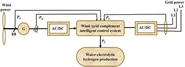 | ||
| Fig. 21 Circuit diagram of non-grid-connected wind power/water-electrolytic hydrogen production system. Modified from ref. 243 with permission from Elsevier, copyright 2012. | ||
Electricity generation from wind energy illustrated minimum negative impacts on the environment compared with the other energy resources.244 In 2012, about 282![[thin space (1/6-em)]](https://www.rsc.org/images/entities/char_2009.gif) 275 MW electricity was generated by wind energy which was around 2% of total world electricity demand. The USA, China, Germany, Spain, and India generate more than 73% of annual worldwide wind electricity.245 In order to utilise the maximum capacity of wind power, complex wind power plants should be managed wisely. For instance, in some wind power plants around the world, the transportation capacity of the electricity grid should be upgraded and additional power capacity should be installed to prepare a backup for the installed wind power system.
275 MW electricity was generated by wind energy which was around 2% of total world electricity demand. The USA, China, Germany, Spain, and India generate more than 73% of annual worldwide wind electricity.245 In order to utilise the maximum capacity of wind power, complex wind power plants should be managed wisely. For instance, in some wind power plants around the world, the transportation capacity of the electricity grid should be upgraded and additional power capacity should be installed to prepare a backup for the installed wind power system.
Wind energy can vary due to meteorological changes, which increases the demand for balancing power in load frequency regulation. Such issues might be resolved using a water electrolysis-based wind-to-hydrogen (WTH) technique. In times of low wind potential or after grid congestion has subsided, the excess electricity is stored as hydrogen and converted back into electricity.246 For both grid-connected systems and isolated grid systems, electrolytic hydrogen's potential as a storage medium for wind energy in network balancing has been researched.247,248 Hydrogen serves as a buffer for wind power facilities to control changes in wind power due to the synergy between the sectors of hydrogen energy and wind power.249 Additionally, the WTH system has a great deal of potential for use in light-duty cars as a clean fuel to reduce rising GHG rates.250 An integrated system for producing electricity from wind energy and using hydrogen is shown in Fig. 22.251
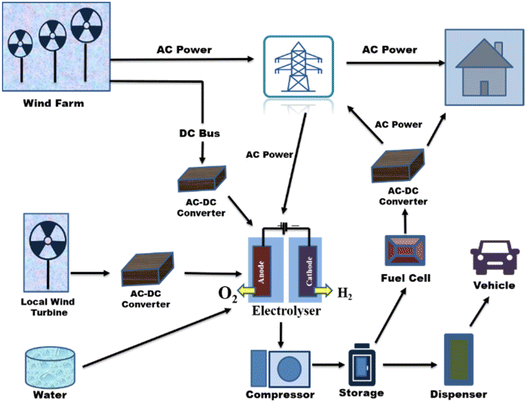 | ||
| Fig. 22 Integrated wind energy system for producing electricity and hydrogen. Modified from ref. 34 with permission from Elsevier, copyright 2016. | ||
Based on the production of hydrogen from natural gas and gasoline as non-renewable fuels, Granovskii et al. completed a life cycle assessment (LCA) of hydrogen and power generation from wind and solar technologies as renewable resources. It was stated that the cost of hydrogen produced through the reforming of renewable sources is higher.252 Additionally, it was noted that WTH for hydrogen vehicles fuel cells instead of gasoline can result in a cost-effective reduction of GHG emissions when the efficiency of an hydrogen vehicle is two times higher than an internal combustion vehicle.253 Due to the high cost of newly installed equipment and energy loss from inefficient energy conversion processes, hydrogen produced from wind energy is expensive.254
According to Harrison et al., the National Renewable Energy Laboratory (NREL) in the US oversaw the testing of a WTH pilot scale that connects 100 K wind turbines with polymer electrolyte membrane (PEM) and an air energy storage (AES) system that produces 20 kg of hydrogen per day. The price of the hydrogen produced by this technique is approximately $5.50 per kg; however, this price can be reduced by installing cutting-edge wind turbines, and the cost objective for 2017 was $2 per kg. It is significant that when the price of the WTH system falls to $0.015 per kW h, hydrogen production using the technology might be competitive with hydrogen generation using gasoline.255
3.6. Nuclear energy-powered water electrolysis
It is appealing to use nuclear energy as the main source of energy for hydrogen production because it is adaptable to large-scale hydrogen production and its greenhouse gas emissions are significantly lower than those associated with conventional fossil fuel combustion. Through numerous studies that were published in the open literature in recent years, advancements in nuclear-based hydrogen production have become apparent. Connecting an electrolyser to a nuclear power station is the easiest way to produce hydrogen from nuclear energy (Fig. 23). Such a system has the advantage of being able to run at design load without directly interfering with the grid, which can experience grid overload at times. | ||
| Fig. 23 Approaches for integrating nuclear reactors and water electrolysis for (a) dedicated hydrogen production systems or (b) cogeneration systems of electricity and hydrogen. Modified from ref. 17 with permission from Elsevier, copyright 2012. | ||
The fact that there is no need to modify the reactor is another significant benefit of nuclear/water electrolysis. Such systems were used on nuclear submarines to produce hydrogen and oxygen, which are both necessary for life. The system can be modified to use existing nuclear power reactors to produce off-peak electricity. Nuclear power facilities can operate at constant load with the maximum efficiency and lowest cost of electricity generation by producing hydrogen during off-peak hours. Additionally, potential grid congestion is avoided, enhancing the electrical grid's effectiveness and reliability. Remember that even though tested approaches only achieve less than 55% efficiency, the maximum predicted efficiency of the water electrolysis process is 80%. The presented thermal-to-hydrogen efficiency when coupled to modern light water reactors or advanced light water reactors (ALWRs) is 27%; however, when coupled to modular helium reactors (MHRs) or advanced gas reactors (AGRs), the expected efficiency is 35%.
Nuclear reactors have typically been used to generate electricity using steam power plants. According to studies, if a sustainable fuel like hydrogen is created in addition to electricity, there will be more advantages. When using nuclear energy, higher temperatures and pressures are required for the reactor coolant since the efficiency of power generation typically increases as the working medium's temperature rises. However, the allowed temperatures in nuclear reactors and the corresponding temperatures and pressures of the coolants are what primarily restrict advancements in the power generation efficiency of nuclear power plants. The rates of material corrosion and safety restrictions on nuclear reactors set a limit on coolant parameters.
Numerous studies focus on the advancement of nuclear reactors, which must match certain criteria like providing inexpensive energy and high-temperature heat in order to effectively couple with a hydrogen manufacturing facility. The most promising hydrogen generation systems, in terms of the process heat temperature level they offer, are gas-cooled reactors, molten salt-cooled reactors, and heavy metal-cooled reactors. The various nuclear reactor technologies along with nuclear reactor-adaptable thermally driven hydrogen production processes will complement rather than compete in the development of nuclear-based hydrogen generation in the future.17
4. Electrolysis using organic fuels
Despite the fact that water or steam electrolysis is well recognised, its extensive application is constrained by high operational costs associated with energy use. Utilising an alternative anode reaction for O2 evolution with a lower equilibrium potential can reduce the amount of electrical power needed for electrolysis. Several reactions can be employed to do this, but one that has the potential to be appealing is the use of an organic chemical fuel. Methane gas is one such method, which is used as an anode depolariser.256| Anode: CH4 + 2H2O → CO2 + 8H+ + 8e− | (17) |
| Cathode: 8H+ + 8e− → 4H2 | (18) |
The traditional method of electrolysis is water electrolysis; however, because it uses so much energy, interest in producing hydrogen by methanol electrolysis has grown due to several benefits over traditional water electrolysis.256–258
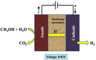
By effectively substituting one unit of electricity with one equivalent energy unit of natural gas at a cheaper cost, this is analogous to electrochemical steam reforming. High system efficiency in terms of primary energy is made possible with the use of natural gas in the electrolyser; voltage reductions of up to 1.0 V in comparison with conventional electrolysers are feasible, and as a result, the electrolyser's electricity consumption can be as low as one-third of that of conventional electrolysers.256–261 However, since it utilises natural gas, this method is not sustainable. Alcohol, which may be produced via fermentation technology, could be the basis of an alternative system. One such methanol-powered cell circulates an aqueous solution past the anode, where methanol and water combine to produce carbon dioxide, much like that in a direct methanol fuel cell:256
| Anode: CH3OH + H2O → CO2 + 6H+ + 6e− | (19) |
| Cathode: 6H+ + 6e− → 3H2 | (20) |
The electrolysis was carried out using a DC power supply to deliver a constant current to the electrolytic cell. A platinum resistance thermometer was positioned close to the anode surface to gauge the electrolytic cell's temperature. Water and the methanol–water solution were then given to the electrolytic cell's anode. A non-pulsation quantitative pump was used to regulate the flow rates, and the electrolytic cell's membrane electrolyte was a Nafion-117 membrane. Both the anode and the cathode catalyst were made of platinum.256 Additionally, methanol cross-over from an anode to a cathode in Nafion membrane methanol electrolysers increases fuel consumption and results in contaminants in the hydrogen produced; as a result, membranes have been further developed to solve this issue.261–264Fig. 24 indicates the electrolysis setup for organic fuel methanol.
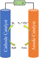
A research study explained the exceptional performance of a CoS2 nanoarray electrode on a titanium mesh substrate (CoS2/TiM) as a highly efficient and durable catalyst for the oxidation of hydrazine in a 1.0 M KOH electrolyte containing 100 mM hydrazine. Achieving a current density of 100 mA cm−2 requires only a low potential of 125 mV. The impressive hydrogen-evolving activity exhibited by CoS2/TiM positions it as a versatile bifunctional catalyst for energy-efficient hydrogen production through electrolysis, where it replaces the conventional water oxidation with hydrazine oxidation. In an electrolyser operating at 100 mA cm−2, CoS2/TiM demonstrates remarkable performance, with a minimal cell voltage requirement of just 0.81 V in a two-electrode setup. Furthermore, it exhibits outstanding long-term electrochemical stability and achieves nearly 100% faradaic efficiency for the evolution of hydrogen gas.265
An effective strategy to substantially reduce the voltage required for water electrolysis is to substitute the anodic OER with the hydrazine oxidation reaction (HzOR) due to its lower thermodynamic oxidation potential. In a study, researchers designed a novel copper–nickel nitride (Cu1Ni2-N) catalyst with a well-defined Cu4N/Ni3N interface on a carbon fiber cloth substrate. This three-dimensional (3D) electrode demonstrates exceptional performance in HER, requiring only a minimal over-potential of 71.4 mV at a current density of 10 mA cm−2 in a 1.0 M KOH solution. Simultaneously, it exhibits an impressively low potential of 0.5 mV at 10 mA cm−2 for HzOR when used in a 1.0 M KOH/0.5 M hydrazine electrolyte. Furthermore, when this synthesized Cu1Ni2-N electrode is employed as both the cathode and anode in an electrolytic cell, it achieves a cell voltage of 0.24 V at 10 mA cm−2 and maintains excellent stability over a 75-hour duration. This research represented a significant step forward in the development of copper–nickel-based nitrides as bifunctional electrocatalysts, leveraging hydrazine assistance to enable energy-efficient hydrogen production through electrolysis (Fig. 25).266
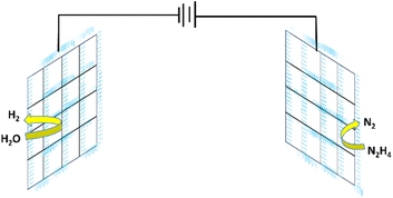 | ||
| Fig. 25 Electrolysis using organic fuel hydrazine. Modified from ref. 266 with permission from Wiley Online Library, copyright 2019. | ||
A research study investigated an energy-efficient alkaline hydrogen production system by substituting the oxygen evolution reaction (OER) with the more oxidizable urea oxidation reaction (UOR). In this context, a bimetal heterostructure, CoMn/CoMn2O4, was engineered to serve as a bifunctional catalyst within an alkaline environment, facilitating both urea oxidation and the hydrogen evolution reaction (HER). The CoMn/CoMn2O4heterostructure, characterized by a Schottky heterojunction structure, enables spontaneous charge transfer at the interface. This feature enhances the adsorption of reactant molecules and the breaking of chemical bonds, thereby initiating the decomposition of both water and urea. Consequently, the heterostructured electrode demonstrated remarkably low potentials of −0.069 V and 1.32 V (versus the reversible hydrogen electrode) to attain current densities of 10 mA cm−2 for HER and UOR, respectively, in an alkaline solution. Furthermore, the complete urea electrolysis driven by CoMn/CoMn2O4 achieves a current density of 10 mA cm−2 at a relatively modest potential of 1.51 V and maintains stable performance for over 15 hours. This innovative approach involving Mott–Schottky hybrids in electrocatalysts represents a promising avenue for sustainable energy conversion, merging hydrogen production with sewage treatment for environmentally responsible applications (Fig. 26).267
In another study researchers substituted the OER with the thermodynamically preferred 5-hydroxymethylfurfural (HMF) that gives 2,5 furan dicarboxylic acid (FDCA) on oxidation. They created three-dimensional (3D) hybrid electrocatalytic electrodes by layering nanosized graphene oxide as a building block. These electrodes were capable of aiding both HMF conversion and the hydrogen evolution process (HER) at the same time. The nanoarchitecture of the electrode, comprising the thickness and position of gold (Au) and palladium (Pd) nanoparticles (NPs), was found to have a substantial influence on electrocatalytic performance. Even when the same constituent NPs were used, the electrodes demonstrated highly adjustable performance via reaction kinetics and diffusion-controlled mechanisms. Furthermore, in a full-cell setting, a bifunctional two-electrode electrolyser optimised for HMF oxidation and HER had the highest overall electrocatalytic activity.
| Anode: HMF + 6OH− → FDCA + 4H2O + 6e− |
| Cathode: 6H2O + 6e− → 3H2 + 6OH− |
| Overall HMF + 2H2O → FDCA + 3H2 |
In a recent study, researchers introduced a novel integrated electrode composed of CoNiP nanosheets with a dual functionality. The CoNiP-NIE serves to enhance the HER while also replacing the OER with the oxidation reaction of 5-hydroxymethylfurfural to produce the valuable compound 2,5-furandicarboxylic acid (FDCA). The newly designed electrode achieves a high faradaic efficiency exceeding 82% for HMFOR over a wide potential range, from 1.40 V to 1.70 V vs. RHE (reversible hydrogen electrode), which surpasses the performance of previously reported electrocatalysts. Furthermore, the low overpotential required for HER underscores its effectiveness in hydrogen (H2) generation. Leveraging the bifunctional properties of CoNiP, researchers constructed an electrochemical device that combines hydrogen evolution with biomass oxidation. This device exhibits a lower voltage requirement (1.46 V) for anode oxidation compared with traditional water splitting (1.76 V) and achieves a higher H2 evolution rate (41.2 L h−1 1 m−2) under the given conditions (Fig. 27).
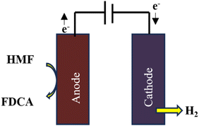 | ||
| Fig. 27 Schematic illustration of HMFOR and HER. Modified from ref. 268 with permission from Elsevier, copyright 2022. | ||
5. Hydrogen as a by-product from electrolysis
Numerous electrolyses are based on anodic oxidation, which is accompanied at the cathode by hydrogen evolution. The electrolysis of the halides results in a variety of compounds, which is notable. The chemistry and electrochemistry of the halides (Br, Cl, and I) involve reactions that are quite similar, although the values of the kinetic and thermodynamic parameters vary. Chlorine electrochemistry is a significant field of industry. An important illustration is the electrolysis of sodium chloride to produce chlorine and sodium hydroxide (the chlor-alkali process). The desired reaction in the electrolysis of a sodium chloride solution is the production of chlorine at the anode, while in an alkali solution the cathode reaction results in the formatting of hydrogen gas and hydroxide ions.269| Anode: 2Cl− → Cl2 + 6H+ + 6e− | (21) |
| Cathode: 6H+ + 6e− → 3H2 | (22) |
It is possible to collect hydrogen gas by separating the anode and cathode reaction products so that they do not react. Other electrolyses of sodium chloride, depending on the circumstances, can generate substances such sodium hypochlorite, chlorate, and perchlorate in addition to hydrogen (at the cathode):
| NaCl + H2O → NaOCl + H2 (Overall hypochlorite reaction) | (23) |
| NaCl + H2O + Cl2 → NaOCl3 + H2 (Overall chlorate reaction) | (24) |
 | (25) |
The counter electrode additionally produces hydrogen at the cathode as a result of other inorganic syntheses.15
6. Sustainability of hydrogen production
Methods for producing hydrogen are based on seven criteria for sustainability. The first two criteria that need to be looked into have to do with how effectively hydrogen can be produced in accordance with the first and second laws of thermodynamics. Energy efficiency is determined by the first law of thermodynamics, while the second law emphasizes energy efficiency. Since efficiency is typically defined as the desired output divided by the required input, the following equation represents energy efficiency: | (26) |
Here, “m” represents the rate of hydrogen generation in kg s−1, “LHV” represents the lower heating value of hydrogen (calculated as 121 MJ kg−1), and “Ein” denotes the rate of energy consumption in MJ kg−1. It is possible to transform the energy efficiency equation into the exergy efficiency equation as follows:
 | (27) |
 stands for the chemical exergy of hydrogen in the exergy efficiency equation, and “Exin” stands for the rate of exergy input into the process. The energy and exergy efficiencies of the chosen hydrogen production technologies are taken from the literature for this study.270–272
The cost of producing hydrogen is the third factor, and it is crucial, especially when scaling up and commercializing processes. Making sustainable hydrogen more accessible and extensively used on the market is a crucial first step. The least expensive methods for producing hydrogen right now are coal gasification and natural gas reforming, but they also produce the most pollutants. Technologies for carbon capture (CC) can lower the emissions. However, CC pushes up the price of producing hydrogen by 10% to 20%.273
The majority of renewable-based hydrogen production methods are still in their development as compared with conventional, fossil-based solutions. As a result, renewable hydrogen has a greater lifecycle cost than fossil-based hydrogen. However, the price of hydrogen derived from renewable sources has significantly reduced. Due to advancements in materials science and system designs, further cost reductions are anticipated for the majority of upcoming renewable hydrogen production techniques. While renewable hydrogen becomes more reasonably priced on a big scale, fossil-based hydrogen produced through carbon capture can be used as a bridge fuel. The cost information for the chosen hydrogen production technologies has been gathered.20,271,274–276
The probable effects of acidification and global warming according to the life cycle assessment (LCA) make up the fourth and fifth criteria. The LCA method is dependable for determining the true environmental effect.277 Global warming potential (GWP) measures the amount of CO2 emissions compared with the amount of H2 produced. Acidification potential (AP) measures the amount of waste that is discharged into the land and water in grams of SOx per kilogram of H2 generated. The two environmental impact metrics that are most frequently employed are GWP and AP.278 According to the literature, renewable hydrogen has a distinct advantage over fossil-based hydrogen in terms of GWP and AP.270,271,273,279
Cost of carbon (CC) is the sixth criterion. According to the harm done to the environment and human health, CC calculates the marginal external cost of a unit of CO2 emissions. The literature has detailed descriptions of the many models used in the calculation of CC.280–284 The seventh criterion, known as the technology maturity level (TML), is rated on a modified, consolidated scale between 1 and 10. The TML facilitates the communication of a technology's maturity level. With regard to unique and small-scale alternatives, grade 1 denotes the extremely early stages of research, and the number 10 denotes complete market integration. Data on the state of technology maturity are taken from ref. 272.
All performance factors are standardized and ranked between 0 and 10 in the final step to carry out the comparison assessment. The optimal choice is 10, whereas the least desired scenario is 0. The technology maturity level is already on a 0–10 scale, where 0 and 10 represent the least and most preferable solutions, respectively, therefore there is no normalization added to it. The chosen hydrogen production techniques perform more sustainably across the board as their score rises from 0 to 10. Efficiency measures for energy and exergy are normalized by:
| Rank (i) = efficiency (i) × 10 | (28) |
The remaining factors (cost of manufacturing, cost of carbon, and potentials for global warming and acidification) are normalized appropriately and ordered as
 | (29) |
Here, the chosen approach is represented by (i). The highest value in the related performance category is indicated by the term “max value” in eqn (29). For example, if a method has the greatest emissions among the options chosen, it receives a score of 0. As an alternative, the option with the highest rating would be the one with the lowest cost. It should be highlighted that zero cost and emissions receive rating 10. No method receives the highest ranking as a result. This strategy seeks to demonstrate that each alternative still has room for improvement across all chosen performance metrics. Each of the chosen hydrogen generation solutions is given a total sustainability score after all performance parameters have been normalized and graded between 0 and 10. The overall scores are compared with the ideal hypothetical case where hydrogen is produced with 100 percent energy and exergy efficiency, zero GWP, AP, and cost, and a TML of ten. The average scores are then determined. Table 7 illustrates detailed sustainability performance rankings of the selected hydrogen production methods. The eight cases used to determine average scores are as follows:210
EI: All factors are equally important.
EE: Energy efficiency is given a 40% weighting, and the remaining criteria are each given a 10% weighting.
ExE: Exergy efficiency is given a 40% weighting, and the remaining criteria are each given a 10% weighting.
CC: The weight for the cost of carbon is 40%, and the remaining criteria are each given a 10% weight.
Cost: Production cost is given a 40% weighting, while the remaining criteria are each given a 10% weighting.
AP: AP is given a 40% weighting, and the remaining criteria are each given a 10% weighting.
GWP: The weight for GWP is 40%, and the remaining criteria are each given a 10% weight.
TML: TML is given a 40% weighting, and the remaining criteria are each given a 10% weighting.
| EI | EE | ExE | CC | Cost | AP | GWP | TML | |
|---|---|---|---|---|---|---|---|---|
| Electrolysis (large scale) | 7.7 | 7.7 | 6.5 | 8.3 | 7.1 | 8.1 | 8.3 | 8.1 |
| PV electrolysis | 4.6 | 3.6 | 3.4 | 5.6 | 3.5 | 5.5 | 5.6 | 4.7 |
| High-temperature electrolysis | 6.3 | 6.9 | 5.5 | 6.9 | 5.2 | 7.0 | 6.9 | 5.6 |
| Photoelectrochemical cell | 4.8 | 3.6 | 3.4 | 6.3 | 3.4 | 6.3 | 6.3 | 4.6 |
| Ideal | 10.0 | 10.0 | 10.0 | 10.0 | 10.0 | 10.0 | 10.0 | 10.0 |
In the twenty-first century, sustainable energy systems are expected to play significant roles in the supply and demand aspects of the use of current sources. Identification of dependable, economical, plentiful, and clean sources for H2 production is a necessity. There is much work being done to create and improve systems that manufacture H2 more cheaply from renewable resources in order to further reduce emissions and energy use.
Hydrogen is widely regarded as an environmentally friendly secondary source of renewable energy and a viable replacement for fossil fuels because it is the only fuel that is carbon-free, and has the largest energy density of any fuel known.285–287 Another benefit is that hydrogen can be used for domestic consumption and can be safely transported using conventional transportation methods.288–291 It can also be stored as compressed gas, cryogenic liquid, or solid hydride in order to be fed to stationary fuel cells.292–294 A minor portion is utilisation in cars, and applications such as power generation and heating in the residential and industrial sectors are anticipated in the near future.290,295,296
The cost of alternative energy sources and novel H2 generation techniques is falling, while the effectiveness of H2-based energy conversion systems is rising. H2 is therefore anticipated to achieve future sustainability objectives.297 Options for electrolysis based on photovoltaics are also thought to be viable for producing hydrogen sustainably.20 Unfortunately, the low conversion efficiency and the high investment costs are major barriers to the competitiveness of water-splitting technologies compared with conventional approaches. Integrating storage, transportation, and hydrogen generation based on renewable energy sources is essential for sustainable hydrogen production.298 Hydrogen must be produced in clean, dependable, cost-effective, and safe ways that do not harm society or the environment in order for hydrogen systems to be acceptably sustainable. The following important factors should be taken into account:
• Technical performance (energy efficiencies, process control, raw material input),
• Social performance (impact on public health, employment and training opportunities, and public acceptance),
• Environmental performance (greenhouse gas emissions, land use, water discharge quality, and solid waste), and
• Availability/reliability (dependence on imported resources, predictability, and scalability).
Grid electrolysis (electricity from fossil fuels), wind electrolysis, solar electrolysis, nuclear thermochemical water-splitting cycles, solar thermochemical water-splitting cycles, and photoelectrochemical cells are some of the current and prospective hydrogen generation technologies. Grid electrolysis is anticipated to hold the key to more environmentally friendly hydrogen production in the near future as other technologies develop and their costs come down. In the long run, wind electrolysis and solar thermochemical water-splitting cycles will be promising methods for producing sustainable hydrogen.299 Research into new, better-performing (ideally abundant) materials is necessary to enable all of these technologies to attain greater sustainability while aiming for cost reduction. A possible route to 100% sustainably produced hydrogen in the energy sector is shown in Fig. 28.
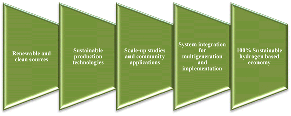 | ||
| Fig. 28 A potential pathway to reach 100% sustainable hydrogen in the energy market. Modified from ref. 210 with permission from Elsevier, copyright 2022. | ||
7. Hydrogen economy
The cost of feedstock, the efficiency of the technology used, the stage of development (e.g., early stage or mature), and the physical proximity to end-use markets (centralized or distributed production) are just a few of the many factors that affect the economics of hydrogen production.300 Investment costs play a large role in determining hydrogen production costs. The production strategy and plant size have an impact on the cost structure. For instance, the fuel cost share ranges from 50 to 68% in large-scale SMRs while it is only between 28 and 40% in small reformer units. Electricity costs account for between 75 and 80 percent of the cost of electrolytic hydrogen. Fuel costs for biomass gasification are roughly 40%. Regarding the evolution of feedstock prices, natural gas is forecast to cost more during the following ten years, while coal is anticipated to cost the same. Costs of electricity are significantly influenced by changes in the price of feedstocks, particularly fossil fuels.A cheap and sustainable source of hydrogen is necessary for the Hydrogen Economy to succeed in the future. Presently, fossil fuels like coal and natural gas are mostly used to produce hydrogen. However, the availability of both of these fuels is constrained, and the creation of hydrogen results in the release of greenhouse gases. Therefore, in order to produce hydrogen in a hydrogen economy, alternative energy sources must be investigated for both environmental and economic reasons. The cost of operating fossil fuel facilities is rising, whereas the cost of alternative energy technology is falling as economies of scale are reached, even if historically the cost of hydrogen from fossil fuel plants has been less expensive than that from other energy sources. In the electrochemical production of hydrogen, the cost of producing hydrogen using the existing light water reactors with electrolysis is greater and is anticipated to range from 4.36 to 7.36 $ per kg, which would not be regarded as a low-cost energy source in light of current gasoline prices.22 Costs for electrochemical methods of producing hydrogen are shown in Table 8.15 The projected costs for PEM electrolysis and SOE to produce hydrogen are now $5.25 per kg and $4.7 per kg, respectively. According to future predictions, using electricity generated from renewable resources, electrolysis-produced hydrogen will cost ca. $2 per kg. The cost of solar thermochemical hydrogen is approximately $2.5 per kg. Currently, there are roughly 0.1 GT of hydrogen produced annually, most of which is used locally to produce ammonia or to refine and treat metals.286,295
| Electrochemical hydrogen production methods | Production costs $ per kg of H2 |
|---|---|
| SOE electrolysis | 4.7–3.8 (forecast) |
| PEM electrolysis | 5.25–4.5 (forecast) |
| Solar electrolysis | 2.0 |
Compared with other methodologies, creating hydrogen gas with wind and solar energy is more expensive. This scenario is the result of a number of economic and technological variables, including the cost of maintenance work, the technology used in power systems, and the price of electricity generated by wind and solar systems. The high expenses of distributed and small-scale manufacturing in comparison with the industrial size of conventional power facilities is another factor. Unfortunately, carbon-based conversion is the most cost-effective way for producing hydrogen (steam methane reforming, coal and biomass gasification). Although many people believe that nuclear energy can produce hydrogen at a scale that is economically viable, there are still a number of restrictions and technical issues that need to be resolved.301
The overall system has a significant impact on the efficiency of the conversion from electricity to hydrogen and back to electricity. The efficiency of hydrogen production from low-temperature electrolysis will be no higher than 25%. However, by switching from low to high-temperature electrolysis, which produces steam at 800 °C, and by using advanced nuclear plants with higher thermal-to-electric conversion efficiencies, this conversion might be increased (Table 9).302
| Conversion routes | Conversion efficiency (%) |
|---|---|
| Nuclear heat + electrolysis | 28 |
| Wind + electrolysis | 70 |
| Solar PV + electrolysis | 10.5 |
| Hydroelectric + electrolysis | 70 |
| Tidal + electrolysis | 70 |
Examples of the technical, economic, and environmental aspects of systems for producing hydrogen using fossil and non-fossil fuels may be found widely in the literature.270,271 For instance, Dawood et al.272 have examined the function of hydrogen in future energy systems and suggested a pathway toward 100% renewable energy systems. The current situation of the hydrogen supply chain is depicted as an advancing energy vector in the techno-economic assessment of hydrogen production methods, which includes resources, generating and storage technologies, demand market, and economics. Ji and Wang have studied the state-of-the-art, most recent developments, and difficulties of both fossil- and renewable-based hydrogen production techniques. They have come to the conclusion that electrolysis and thermochemical cycles in combination with renewable energy sources exhibit significant economic and environmental promise (Table 10).273
| Process hydrogen from | Production mode | Cost (€ per GJ) | ||
|---|---|---|---|---|
| Feedstock | Production | Final (incl. storage, delivery, dispensing) | ||
| Coal gasification | Centralized | 1.2 | 13–16 | 32–37 |
| Methane reforming | Centralized (3 M Nm3 d−1) | 3 | 5–8 | 22–30 |
| Biomass gasification | Intermediate | 2.4 | 17–22 | 33–40 |
| Methane reforming | Decentralized | 4–5 | 7–12 | 28–33 |
| Gasoline | Refinery | 2.5 | 6 | 7 |
| Electrolysis | Decentralized | 14 | 20–25 | 35–40 |
8. Conclusion
Most of the hydrogen is produced (95%) from hydrocarbons after reacting with steam. In order to produce hydrogen from non-fossil natural resources in substantial amounts, a hydrogen-based energy system will need to rely on low-cost and effective methods. Using electrolysis, which primarily uses renewable energy sources and water, accounts for only 4% of global hydrogen production. The amounts of hydrogen needed are enormous and orders of magnitude more than what is now produced, according to estimates from different nations. Splitting water, which is a perfect hydrogen transporter, is the most sustainable method of obtaining hydrogen. Hydrogen and oxygen are split from water by electrolysis, a practical and proven process that today yields very pure hydrogen for usage in the electronics, pharmaceutical, and food sectors. Due to the fact that water electrolysis only necessitates a modest amount of storage, it is a safe choice for producing hydrogen at the point of use in relatively small quantities. Around 80% of the cost of producing hydrogen comes from the electricity needed to electrolyse water and separate it into hydrogen and oxygen. Potentially, electrolysis can produce a clean and renewable energy supply when combined with a renewable energy source. However, electrolysis by itself would not be able to produce all the hydrogen anticipated to be required for upcoming energy demands. Although pilot systems are being investigated, the use of solar radiation for heating and/or photocatalysis shows considerable promise but still needs further research and development. This is currently being conducted on photoelectrochemical catalysts that create hydrogen when exposed to visible light in order to increase their robustness, efficiency, and material costs. There are many choices of methods for producing hydrogen that might be sustainable and prevent this consumption of fossil fuels. However, for them to develop there must be both significant capital investments in the infrastructure and political legislation-driven incentive. Different electrochemical methods have been discussed in detail in this study including wind, solar and nuclear-assisted water electrolysis, high and low-temperature water electrolysis, electrolysis using organic fuels and hydrogen production as a by-product of various electrolytic methods. This review makes an effort to do just that while also going detailing the economics and status of industrial and development electrolysis.9. Future perspectives
In general, electrolysis is regarded as a well-known alternative technique for producing hydrogen that has already attained a significant market potential. Megawatt-scale units are already available, and problems with project production and supply chain development are also being addressed. Between the years 2020 and 2025 electrolysis is expected to become a marketable technology. The systems’ durability is now a limitation of electrolysis technology; however, owing to intensive research, these issues should be solved in the upcoming decades. The viability will depend on the cost of the required renewable electricity. There are several future perspectives which are given below:1. Resolving durability challenges
One of the primary challenges facing electrolysis technology is the durability of the systems. However, through extensive research and development efforts, it is anticipated that these difficulties will be overcome in the coming decades. This improvement in durability is a critical step in making electrolysis a more reliable and long-lasting technology.
2. Cost-effective hydrogen production
The viability of electrolysis for hydrogen production is closely tied to the cost of renewable electricity. As renewable energy sources become more accessible and affordable, the cost-effectiveness of electrolysis is expected to increase. This shift is particularly significant as we strive to reduce carbon emissions and transition to a cleaner energy landscape.
3. Advancements in solid oxide electrolysis (SOE)
Solid Oxide Electrolysis (SOE) systems are poised to become more economical and durable in the next decade. They are expected to catch up with traditional alkaline and PEM electrolysis technologies by 2030. This advancement in SOE technology will contribute to a more diverse and competitive hydrogen production landscape.164
4. Nuclear-powered hydrogen production
A prospective approach involves utilizing electrolytically produced hydrogen derived from nuclear power sources. This method enables the generation and storage of hydrogen during periods of low electrical demand, which can then be converted back into energy during peak demand. As natural gas prices rise, the stability of nuclear power steam generation becomes increasingly attractive, offering a reliable alternative for hydrogen production.310
5. Carbon-neutral hydrogen production
The quest for cost-effective hydrogen production without emitting carbon dioxide remains a top priority. As technology continues to advance, there is a strong possibility that we will achieve the goal of producing hydrogen in an environmentally friendly and economically viable manner. The recent developments in this area are highlighted.210
6. Underground seasonal hydrogen storage (USHS)
To secure the energy supply chain for a hydrogen-based future, large-scale energy storage technologies are essential. Underground Seasonal Hydrogen Storage (USHS) is emerging as a viable method to address the temporal fluctuations in renewable energy output. Geological research, including assessments of geochemical and biological reactions, is critical to its success. The connection between hydrogen demand and various applications, such as ammonia generation and integration into power systems, will shape the future energy landscape.311
7. Collaboration and diverse production technologies
Collaboration between government agencies, industry leaders, and educational institutions is crucial for driving advancements in hydrogen production. Both centralized and decentralized methods of hydrogen production are under investigation. Prioritizing the improvement of existing commercial methods, while also exploring cutting-edge technologies such as direct photon-to-hydrogen energy-based water-splitting, will lead to diverse and efficient production configurations.
8. Policy adjustments and technological advancements
To achieve these goals, several steps and policy adjustments are recommended:14
i. Foster technology and market development: Government support should prioritize the development of carbon dioxide capture and absorption technologies and the advancement of renewable and low-carbon-emitting methods.
ii. Improve gas separation and purification techniques: Research into high-efficiency hydrogen purification technologies suitable for distributed reformers is essential.
iii. Invest in small reformers: Utilizing small reformers powered by various fuels can reduce the cost of hydrogen supply, with a focus on reliability and compatibility with fuel cells.
iv. Reduce electrolyser expenses and maximize efficiency: Continuous improvement in electrolyzer efficiency and cost reduction is vital, especially for decentralized power generation.
v. Explore innovative photolytic processes: Advancements in photolytic processes that use light energy for hydrogen production should be a research priority, with a focus on efficiency and corrosion resistance.
vi. Nuclear-powered hydrogen: Develop cost-effective and environmentally friendly methods for producing hydrogen from nuclear energy, leveraging advanced nuclear reactor technology.
vii. Carbon dioxide collection and sequestration: Integrate carbon dioxide capture systems into hydrogen production plants to minimize carbon emissions.
viii. Demonstrations and technology integration: Showcase hydrogen production technology alongside practical examples to generate market interest and promote safety.
ix. Large-scale testing sites: Establish dedicated sites for large-scale testing and technology display to address logistical challenges.
In conclusion, the future of hydrogen production through electrolysis is bright, with a range of advancements on the horizon. Through collaborative efforts, technological innovation, and policy support, we can build a reliable and efficient hydrogen production system that plays a pivotal role in a sustainable energy future.
Conflicts of interest
The authors declare no conflict of interest.Acknowledgements
Support from Cardiff University to Dr Nisar Ahmed is gratefully acknowledged.References
- R. A. Hites, Persistent organic pollutants in the Great Lakes, 2005, pp. 1–12 Search PubMed.
- H. Lund, Energy, 2007, 32, 912–919 CrossRef.
- K. Blok, Energy Policy, 2005, 33, 1635–1641 CrossRef.
- J. Turner, G. Sverdrup, M. K. Mann, P. C. Maness, B. Kroposki, M. Ghirardi, R. J. Evans and D. Blake, Int. J. Energy Res., 2008, 32, 379–407 CrossRef CAS.
- K. T. Møller, T. R. Jensen, E. Akiba and H.-w. Li, Prog. Nat. Sci.: Mater. Int., 2017, 27, 34–40 CrossRef.
- J.-S. Kim, D.-C. Lee, J.-J. Lee and C.-W. Kim, Sci. Rep., 2020, 10, 15586 CrossRef CAS PubMed.
- M. Ball and M. Weeda, Int. J. Hydrogen Energy, 2015, 40, 7903–7919 CrossRef CAS.
- I. Staffell, D. Scamman, A. V. Abad, P. Balcombe, P. E. Dodds, P. Ekins, N. Shah and K. R. Ward, Energy Environ. Sci., 2019, 12, 463–491 RSC.
- G. E. Badea, C. Hora, I. Maior, A. Cojocaru, C. Secui, S. M. Filip and F. C. Dan, Energies, 2022, 15, 8560 CrossRef CAS.
- B. Ewan and R. Allen, Int. J. Hydrogen Energy, 2005, 30, 809–819 CrossRef CAS.
- C. M. Kalamaras and A. M. Efstathiou, Conference Papers in Energy, 2013, DOI:10.1155/2013/690627.
- M. H. Islam, O. S. Burheim and B. Pollet, Ultrason. Sonochem., 2019, 51, 533–555 CrossRef CAS PubMed.
- J. J. Lamb, M. Hillestad, E. Rytter, R. Bock, A. S. Nordgård, K. M. Lien, O. S. Burheim and B. G. Pollet, in Hydrogen, biomass and bioenergy, Elsevier, 2020, pp. 21–53 Search PubMed.
- C. Acar and I. Dincer, Compr. Energy Syst., 2018, 3, 1–40 CAS.
- K. Scott, Electrochemical Methods for Hydrogen Production, 2019, vol. 25, p. 392 Search PubMed.
- F. H. Sobrino, C. R. Monroy and J. L. H. Pérez, Renewable Sustainable Energy Rev., 2010, 14, 772–780 CrossRef CAS.
- I. Dincer, Int. J. Hydrogen Energy, 2012, 37, 1954–1971 CrossRef CAS.
- J. Turner, G. Sverdrup and M. Mann, J. Energy Res., 2008, 32, 379 CrossRef CAS.
- S. S. Kumar and H. Lim, Energy Rep., 2022, 8, 13793–13813 CrossRef.
- P. Nikolaidis and A. Poullikkas, Renewable Sustainable Energy Rev., 2017, 67, 597–611 CrossRef CAS.
- M. Balat and M. Balat, Int. J. Hydrogen Energy, 2009, 34, 3589–3603 CrossRef CAS.
- J. R. Bartels, M. B. Pate and N. K. Olson, Int. J. Hydrogen Energy, 2010, 35, 8371–8384 CrossRef CAS.
- A. Midilli, H. Kucuk, M. E. Topal, U. Akbulut and I. Dincer, Int. J. Hydrogen Energy, 2021, 46, 25385–25412 CrossRef CAS.
- F. Barbir, Energy, 2009, 34, 308–312 CrossRef CAS.
- A. Ahmed, A. Q. Al-Amin, A. F. Ambrose and R. Saidur, Int. J. Hydrogen Energy, 2016, 41, 1369–1380 CrossRef CAS.
- M. F. Milazzo, F. Spina, P. Primerano and J. Bart, Renewable Sustainable Energy Rev., 2013, 26, 579–624 CrossRef.
- M. A. Khan, H. Zhao, W. Zou, Z. Chen, W. Cao, J. Fang, J. Xu, L. Zhang and J. Zhang, Electrochem. Energy Rev., 2018, 1, 483–530 CrossRef CAS.
- M. Bodner, A. Hofer and V. Hacker, Wiley Interdiscip. Rev.: Energy Environ., 2015, 4, 365–381 CAS.
- I. K. Kapdan and F. Kargi, Enzyme Microb. Technol., 2006, 38, 569–582 CrossRef CAS.
- M. Ricci, G. Newsholme, P. Bellaby and R. Flynn, Int. J. Energy Sect. Manag., 2007, 1, 34–50 CrossRef.
- A. Demirbas, Energy Sources, Part B, 2017, 12, 172–181 CrossRef CAS.
- S. V. Mohan, Y. V. Bhaskar and P. Sarma, Water Res., 2007, 41, 2652–2664 CrossRef CAS PubMed.
- A. L. Ortiz, M. M. Zaragoza and V. Collins-Martínez, Int. J. Hydrogen Energy, 2016, 41, 23363–23379 CrossRef.
- S. E. Hosseini and M. A. Wahid, Renewable Sustainable Energy Rev., 2016, 57, 850–866 CrossRef CAS.
- M. Balat, Energy Sources, Part B, 2007, 2, 49–61 CrossRef CAS.
- N. Z. Muradov and T. N. Veziroǧlu, Int. J. Hydrogen Energy, 2005, 30, 225–237 CrossRef CAS.
- A. Ajanovic, M. Sayer and R. Haas, Int. J. Hydrogen Energy, 2022, 47, 24136–24154 CrossRef CAS.
- M. Newborough and G. Cooley, Fuel Cells Bull., 2020, 2020, 16–22 CrossRef.
- M. Noussan, P. P. Raimondi, R. Scita and M. Hafner, Sustainability, 2020, 13, 298 CrossRef.
- Z. Navas-Anguita, D. García-Gusano, J. Dufour and D. Iribarren, Sci. Total Environ., 2021, 771, 145432 CrossRef CAS PubMed.
- A. M. Amin, E. Croiset and W. Epling, Int. J. Hydrogen Energy, 2011, 36, 2904–2935 CrossRef CAS.
- M. Carmo, D. L. Fritz, J. Mergel and D. Stolten, Int. J. Hydrogen Energy, 2013, 38, 4901–4934 CrossRef CAS.
- S. Zhiznin, V. Timokhov and A. Gusev, Int. J. Hydrogen Energy, 2020, 45, 31353–31366 CrossRef CAS.
- A. Konieczny, K. Mondal, T. Wiltowski and P. Dydo, Int. J. Hydrogen Energy, 2008, 33, 264–272 CrossRef CAS.
- S. Wang, A. Lu and C.-J. Zhong, Nano Convergence, 2021, 8, 1–23 CrossRef CAS PubMed.
- M. Rashid, M. K. Al Mesfer, H. Naseem and M. Danish, Int. J. Eng. Adv. Technol., 2015, 4, 80–93 Search PubMed.
- C. Hora, F. C. Dan, N. Rancov, G. E. Badea and C. Secui, Energies, 2022, 15, 6076 CrossRef CAS.
- L. Pérez Orosa, E. Chinarro, D. Guinea and M. C. García-Alegre, Energies, 2022, 15, 5888 CrossRef.
- B. Jenkins, D. Squires, J. Barton, D. Strickland, K. Wijayantha, J. Carroll, J. Wilson, M. Brenton and M. Thomson, Energies, 2022, 15, 5796 CrossRef CAS.
- A. Saravanan, S. Karishma, P. S. Kumar, P. Yaashikaa, S. Jeevanantham and B. Gayathri, Biomass Convers. Biorefin., 2020, 1–21 Search PubMed.
- A. M. Elgarahy, M. Eloffy, A. Hammad, A. N. Saber, D. M. El-Sherif, A. Mohsen, M. Abouzid and K. Z. Elwakeel, Environ. Chem. Lett., 2022, 20, 3453–3504 CrossRef CAS.
- S. M. Saba, M. Müller, M. Robinius and D. Stolten, Int. J. Hydrogen Energy, 2018, 43, 1209–1223 CrossRef CAS.
- Y. Liu, F. Wang, Z. Jiao, S. Bai, H. Qiu and L. Guo, Electrochem. Energy Rev., 2022, 5, 5 CrossRef CAS.
- J. Wang, Z. Zhang, J. Ding, C. Zhong, Y. Deng, X. Han and W. Hu, Sci. China Mater., 2021, 64, 1–26 CrossRef CAS.
- H.-Y. Wang, C.-C. Weng, J.-T. Ren and Z.-Y. Yuan, Front. Chem. Sci. Eng., 2021, 1–19 Search PubMed.
- D. V. Esposito, Joule, 2017, 1, 651–658 CrossRef CAS.
- M. Gong, D.-Y. Wang, C.-C. Chen, B.-J. Hwang and H. Dai, Nano Res., 2016, 9, 28–46 CrossRef CAS.
- X. Li, L. Zhao, J. Yu, X. Liu, X. Zhang, H. Liu and W. Zhou, Nano-Micro Lett., 2020, 12, 1–29 CrossRef CAS PubMed.
- S. Atilhan, S. Park, M. M. El-Halwagi, M. Atilhan, M. Moore and R. B. Nielsen, Curr. Opin. Chem. Eng., 2021, 31, 100668 CrossRef.
- F. Mödinger, InterCeram: Int. Ceram. Rev., 2021, 70, 32–37 Search PubMed.
- B. S. Thapa and B. Thapa, J. Phys.: Conf. Ser. 20201608012020 Search PubMed.
- Y. Zhao, V. McDonell and S. Samuelsen, Int. J. Hydrogen Energy, 2020, 45, 11368–11379 CrossRef CAS.
- H. Balat and E. Kırtay, Int. J. Hydrogen Energy, 2010, 35, 7416–7426 CrossRef CAS.
- L. Hu, G. r. Lindbergh and C. Lagergren, J. Phys. Chem. C, 2016, 120, 13427–13433 CrossRef CAS.
- L. Barelli, G. Bidini, G. Cinti and J. Milewski, Int. J. Hydrogen Energy, 2021, 46, 14922–14931 CrossRef CAS.
- D. Penchini, G. Cinti, G. Discepoli and U. Desideri, Int. J. Hydrogen Energy, 2014, 39, 9457–9466 CrossRef CAS.
- A. Monforti Ferrario, F. Santoni, M. Della Pietra, M. Rossi, N. Piacente, G. Comodi and L. Simonetti, Front. Energy Res., 2021, 9, 655915 CrossRef.
- S. Dresp, T. N. Thanh, M. Klingenhof, S. Brückner, P. Hauke and P. Strasser, Energy Environ. Sci., 2020, 13, 1725–1729 RSC.
- G. E. Badea, I. Maior, A. Cojocaru and I. Corbu, Rev. Roum. Chim., 2007, 52, 1123–1130 CAS.
- A. Cojocaru, G. E. Badea, I. Maior, P. Creţ and T. Badea, Rev. Roum. Chim., 2009, 54, 49–54 CAS.
- G. E. Badea, I. Maior, A. Cojocaru, I. Pantea and T. Badea, Rev. Roum. Chim., 2009, 54, 55–61 CAS.
- W. Zang, T. Sun, T. Yang, S. Xi, M. Waqar, Z. Kou, Z. Lyu, Y. P. Feng, J. Wang and S. J. Pennycook, Adv. Mater., 2021, 33, 2003846 CrossRef CAS PubMed.
- V. V. Kuznetsov, B. I. Podlovchenko, K. V. Frolov, M. A. Volkov and D. A. Khanin, J. Solid State Electrochem., 2022, 26, 2183–2193 CrossRef CAS.
- S. Farhangi, S. Ebrahimi and M. S. Niasar, Biotechnol. Lett., 2014, 36, 1987–1992 CrossRef CAS PubMed.
- S. H. Hsu, J. Miao, L. Zhang, J. Gao, H. Wang, H. Tao, S. F. Hung, A. Vasileff, S. Z. Qiao and B. Liu, Adv. Mater., 2018, 30, 1707261 CrossRef PubMed.
- C. Zhang, D. Li and Y. Xu, J. Mater. Res., 2022, 37, 807–817 CrossRef CAS.
- Z. Chen, D. Liu, Y. Gao, Y. Zhao, W. Xiao, G. Xu, T. Ma, Z. Wu and L. Wang, Sci. China Mater., 2022, 65, 1217–1224 CrossRef CAS.
- Q. Xiong, X. Zhang, Q. Cheng, G. Liu, G. Xu, J. Li, X. Ye and H. Gao, Nano Res., 2021, 14, 1443–1449 CrossRef CAS.
- H. Xie, C. Lan, B. Chen, F. Wang and T. Liu, Nano Res., 2020, 13, 3321–3329 CrossRef CAS.
- L. Dong, G.-R. Chang, Y. Feng, X.-Z. Yao and X.-Y. Yu, Rare Met., 2022, 1–12 Search PubMed.
- J. Li, M. Song, Y. Hu, C. Zhang, W. Liu, X. Huang, J. Zhang, Y. Zhu, J. Zhang and D. Wang, Nano Res., 2023, 16, 3658–3664 CrossRef CAS.
- G. Wang, Y. Sun, Y. Zhao, Y. Zhang, X. Li, L. Fan and Y. Li, Nano Res., 2022, 15, 8771–8782 CrossRef CAS.
- Y. Chen, P. Sun and W. Xing, J. Chem. Sci., 2019, 131, 1–8 CrossRef CAS.
- D. Liang, Y. Liu, S. Peng, F. Lan, S. Lu and Y. Xiang, Front. Environ. Sci. Eng., 2014, 8, 624–630 CrossRef CAS.
- Q. Yu, J. Chi, G. Liu, X. Wang, X. Liu, Z. Li, Y. Deng, X. Wang and L. Wang, Sci. China Mater., 2022, 65, 1539–1549 CrossRef CAS.
- Q. Liu, S. Sun, L. Zhang, Y. Luo, Q. Yang, K. Dong, X. Fang, D. Zheng, A. A. Alshehri and X. Sun, Nano Res., 2022, 15, 8922–8927 CrossRef CAS.
- C. González-Buch, I. Herraiz-Cardona, E. Ortega, J. García-Antón and V. Pérez-Herranz, J. Appl. Electrochem., 2016, 46, 791–803 CrossRef.
- A. Laszczyńska and I. Szczygieł, Int. J. Hydrogen Energy, 2020, 45, 508–520 CrossRef.
- S. Wang, M. Wang, Z. Liu, S. Liu, Y. Chen, M. Li, H. Zhang, Q. Wu, J. Guo and X. Feng, ACS Appl. Mater. Interfaces, 2022, 14, 15250–15258 CrossRef CAS PubMed.
- L. Yu, L. Wu, S. Song, B. McElhenny, F. Zhang, S. Chen and Z. Ren, ACS Energy Lett., 2020, 5, 2681–2689 CrossRef CAS.
- H. Li, Q. Tang, B. He and P. Yang, J. Mater. Chem. A, 2016, 4, 6513–6520 RSC.
- J. Zheng, Y. Zhao, H. Xi and C. Li, RSC Adv., 2018, 8, 9423–9429 RSC.
- S. Gao, G.-D. Li, Y. Liu, H. Chen, L.-L. Feng, Y. Wang, M. Yang, D. Wang, S. Wang and X. Zou, Nanoscale, 2015, 7, 2306–2316 RSC.
- X. Wu, S. Zhou, Z. Wang, J. Liu, W. Pei, P. Yang, J. Zhao and J. Qiu, Adv. Energy Mater., 2019, 9, 1901333 CrossRef.
- J. Miao, Z. Lang, X. Zhang, W. Kong, O. Peng, Y. Yang, S. Wang, J. Cheng, T. He and A. Amini, Adv. Funct. Mater., 2019, 29, 1805893 CrossRef.
- Y. Zhao, B. Jin, Y. Zheng, H. Jin, Y. Jiao and S. Z. Qiao, Adv. Energy Mater., 2018, 8, 1801926 CrossRef.
- Y. Jiao, H. Yan, D. Wang, X. Wang, S. Xu, Y. Xie, A. Wu, L. Jiang, C. Tian and R. Wang, Sci. China Mater., 2022, 65, 1225–1236 CrossRef CAS.
- A. R. Jadhav, A. Kumar, J. Lee, T. Yang, S. Na, J. Lee, Y. Luo, X. Liu, Y. Hwang and Y. Liu, J. Mater. Chem. A, 2020, 8, 24501–24514 RSC.
- Y. Zhao, B. Jin, A. Vasileff, Y. Jiao and S.-Z. Qiao, J. Mater. Chem. A, 2019, 7, 8117–8121 RSC.
- L. Chen and J. Shi, Sci. China Mater., 2022, 65, 1–9 CrossRef CAS.
- J. Hnát, M. Paidar and K. Bouzek, in Current Trends and Future Developments on (Bio-) Membranes, Elsevier, 2020, pp. 91–117 Search PubMed.
- B. Dunn, H. Kamath and J.-M. Tarascon, Science, 2011, 334, 928–935 CrossRef CAS PubMed.
- N. S. Lewis and D. G. Nocera, Proc. Natl. Acad. Sci. U. S. A., 2006, 103, 15729–15735 CrossRef CAS PubMed.
- I. Roger, M. A. Shipman and M. D. Symes, Nat. Rev. Chem., 2017, 1, 0003 CrossRef CAS.
- R. Gao and D. Yan, Adv. Energy Mater., 2020, 10, 1900954 CrossRef CAS.
- R. Gao, J. Zhu and D. Yan, Nanoscale, 2021, 13, 13593–13603 RSC.
- Z. Guo, W. Ye, X. Fang, J. Wan, Y. Ye, Y. Dong, D. Cao and D. Yan, Inorg. Chem. Front., 2019, 6, 687–693 RSC.
- X.-W. Lv, Z.-P. Hu, L. Chen, J.-T. Ren, Y.-P. Liu and Z.-Y. Yuan, ACS Sustainable Chem. Eng., 2019, 7, 12770–12778 CrossRef CAS.
- Y. Zheng, Y. Jiao, A. Vasileff and S. Z. Qiao, Angew. Chem., Int. Ed., 2018, 57, 7568–7579 CrossRef CAS PubMed.
- J.-T. Ren, Y. Yao and Z.-Y. Yuan, Green Energy Environ., 2021, 6, 620–643 CrossRef CAS.
- M. A. Mushtaq, M. Arif, G. Yasin, M. Tabish, A. Kumar, S. Ibraheem, W. Ye, S. Ajmal, J. Zhao and P. Li, Renewable Sustainable Energy Rev., 2023, 176, 113197 CrossRef CAS.
- M. A. Mushtaq, A. Kumar, G. Yasin, M. Arif, M. Tabish, S. Ibraheem, X. Cai, W. Ye, X. Fang and A. Saad, Appl. Catal., B, 2022, 317, 121711 CrossRef CAS.
- J.-W. Zhang, H. Zhang, T.-Z. Ren, Z.-Y. Yuan and T. J. Bandosz, Front. Chem. Sci. Eng., 2021, 15, 279–287 CrossRef.
- J. Wang, S.-J. Kim, J. Liu, Y. Gao, S. Choi, J. Han, H. Shin, S. Jo, J. Kim and F. Ciucci, Nat. Catal., 2021, 4, 212–222 CrossRef CAS.
- J. Rossmeisl, A. Logadottir and J. K. Nørskov, Chem. Phys., 2005, 319, 178–184 CrossRef CAS.
- C. C. Weng, J. T. Ren and Z. Y. Yuan, ChemSusChem, 2020, 13, 3357–3375 CrossRef CAS PubMed.
- J.-T. Ren, Y.-J. Song and Z.-Y. Yuan, J. Energy Chem., 2019, 32, 78–84 CrossRef.
- J. A. Turner, Science, 2004, 305, 972–974 CrossRef CAS PubMed.
- C. Xiang, K. M. Papadantonakis and N. S. Lewis, Mater. Horiz., 2016, 3, 169–173 RSC.
- M. Cuartero, G. Crespo, T. Cherubini, N. Pankratova, F. Confalonieri, F. Massa, M.-L. Tercier-Waeber, M. Abdou, J. r. Schäfer and E. Bakker, Anal. Chem., 2018, 90, 4702–4710 CrossRef CAS PubMed.
- Z. Wang, Y. Gu and L. Wang, Front. Energy, 2021, 15, 596–599 CrossRef.
- F. Esmaeilion, Appl. Water Sci., 2020, 10, 84 CrossRef CAS.
- Y. Kuang, M. J. Kenney, Y. Meng, W.-H. Hung, Y. Liu, J. E. Huang, R. Prasanna, P. Li, Y. Li and L. Wang, Proc. Natl. Acad. Sci. U. S. A., 2019, 116, 6624–6629 CrossRef CAS PubMed.
- R. A. Evrin and I. Dincer, Energy Storage, 2020, 2, e195 CrossRef.
- A. Headley, G. Randolf, M. Virji and M. Ewan, MRS Energy Sustainability, 2020, 7, E26 CrossRef.
- F. Musharavati, P. Ahmadi and S. Khanmohammadi, J. Therm. Anal. Calorim., 2021, 145, 1673–1689 CrossRef CAS.
- S. Serag and A. Echchelh, Technol. Econ. Smart Grids Sustain. Energy, 2022, 7, 30 CrossRef.
- K. Meier, Int. J. Energy Environ. Eng., 2014, 5, 1–12 CrossRef CAS.
- Y. Gao, W. Yao, J. Wang and Z. Cui, J. Therm. Sci., 2023, 32, 93–108 CrossRef CAS.
- S. Rarotra, T. K. Mandal and D. Bandyopadhyay, Energy Technol., 2017, 5, 1208–1217 CrossRef CAS.
- M. R. Omidvar, A. H. Meghdadi Isfahani, R. Kumar, A. Mohammadidoust and A. Bewoor, Biomass Convers. Biorefin., 2021, 1–19 Search PubMed.
- M. Rezaei, A. Mostafaeipour, M. Qolipour and M. Momeni, Front. Energy, 2019, 13, 539–550 CrossRef.
- P. D. Cavaliere, A. Perrone and A. Silvello, Metals, 2021, 11, 1816 CrossRef CAS.
- R. Banik and P. Das, J. Inst. Eng. (India): Ser. B, 2020, 101, 527–539 Search PubMed.
- S. Furfari and A. Clerici, Eur. Phys. J. Plus, 2021, 136, 509 CrossRef CAS.
- S. Chai, G. Zhang, G. Li and Y. Zhang, Clean Technol. Environ. Policy, 2021, 23, 1931–1946 CrossRef.
- K. Jing, C. Liu, X. Cao, H. Sun and Y. Dong, J. Electr. Eng. Technol., 2021, 16, 2355–2365 CrossRef.
- H. Niaz, M. M. Lakouraj and J. Liu, Korean J. Chem. Eng., 2021, 38, 1617–1630 CrossRef CAS.
- S. Rawat, B. Jha and M. K. Panda, Iran. J. Sci. Technol., Trans. Electr. Eng., 2018, 42, 403–417 CrossRef.
- M. G. Shirkoohi, R. D. Tyagi, P. A. Vanrolleghem and P. Drogui, J. Environ. Health Sci. Eng., 2022, 20, 1089–1109 CrossRef CAS PubMed.
- J. Brauns and T. Turek, Processes, 2020, 8, 248 CrossRef CAS.
- L. Vidas and R. Castro, Appl. Sci., 2021, 11, 11363 CrossRef CAS.
- O. Schmidt, A. Gambhir, I. Staffell, A. Hawkes, J. Nelson and S. Few, Int. J. Hydrogen Energy, 2017, 42, 30470–30492 CrossRef CAS.
- R. Vakulchuk, I. Overland and D. Scholten, Renewable Sustainable Energy Rev., 2020, 122, 109547 CrossRef.
- M. Ingram, B. Baron and G. Janz, Electrochim. Acta, 1966, 11, 1629–1639 CrossRef CAS.
- H. Bartlett and K. Johnson, J. Electrochem. Soc., 1967, 114, 457 CrossRef CAS.
- B. Kaplan, H. Groult, A. Barhoun, F. Lantelme, T. Nakajima, V. Gupta, S. Komaba and N. Kumagai, J. Electrochem. Soc., 2002, 149, D72 CrossRef CAS.
- V. Kaplan, E. Wachtel, K. Gartsman, Y. Feldman and I. Lubomirsky, J. Electrochem. Soc., 2010, 157, B552 CrossRef CAS.
- H. V. Ijije, C. Sun and G. Z. Chen, Carbon, 2014, 73, 163–174 CrossRef CAS.
- H. V. Ijije, R. C. Lawrence, N. J. Siambun, S. M. Jeong, D. A. Jewell, D. Hu and G. Z. Chen, Faraday Discuss., 2014, 172, 105–116 RSC.
- H. V. Ijije, R. C. Lawrence and G. Z. Chen, RSC Adv., 2014, 4, 35808–35817 RSC.
- D. Chery, V. Albin, V. Lair and M. Cassir, Int. J. Hydrogen Energy, 2014, 39, 12330–12339 CrossRef CAS.
- D. Chery, V. Lair and M. Cassir, Electrochim. Acta, 2015, 160, 74–81 CrossRef CAS.
- J. Ren, F.-F. Li, J. Lau, L. González-Urbina and S. Licht, Nano Lett., 2015, 15, 6142–6148 CrossRef CAS PubMed.
- J. Ren, J. Lau, M. Lefler and S. Licht, J. Phys. Chem. C, 2015, 119, 23342–23349 CrossRef CAS.
- J. P. Perez-Trujillo, F. Elizalde-Blancas, M. Della Pietra and S. J. McPhail, Appl. Energy, 2018, 226, 1037–1055 CrossRef CAS.
- J. P. Pérez-Trujillo, F. Elizalde-Blancas, S. J. McPhail, M. Della Pietra and B. Bosio, Appl. Energy, 2020, 263, 114630 CrossRef.
- L. Hu, I. Rexed, G. Lindbergh and C. Lagergren, Int. J. Hydrogen Energy, 2014, 39, 12323–12329 CrossRef CAS.
- E. Audasso, K. I. Kim, G. Accardo, H. S. Kim and S. P. Yoon, J. Power Sources, 2022, 523, 231039 CrossRef CAS.
- W. Dönitz and E. Erdle, Int. J. Hydrogen Energy, 1985, 10, 291–295 CrossRef.
- A. Nechache and S. Hody, Renewable Sustainable Energy Rev., 2021, 149, 111322 CrossRef CAS.
- Y. Zheng, Z. Chen and J. Zhang, Electrochem. Energy Rev., 2021, 4, 508–517 CrossRef CAS.
- Y. Li, L. Zhang, B. Yu, J. Zhu and C. Wu, Engineering, 2023, 21, 101–114 CrossRef CAS.
- D. Guban, I. K. Muritala, M. Roeb and C. Sattler, Int. J. Hydrogen Energy, 2020, 45, 26156–26165 CrossRef CAS.
- M. Schalenbach, A. R. Zeradjanin, O. Kasian, S. Cherevko and K. J. Mayrhofer, Int. J. Electrochem. Sci., 2018, 13, 1173–1226 CrossRef CAS.
- M. Wang, G. Wang, Z. Sun, Y. Zhang and D. Xu, Global Energy Interconnect., 2019, 2, 436–443 CrossRef.
- V. Romano, G. D'Angelo, S. Perathoner and G. Centi, Energy Environ. Sci., 2021, 14, 5760–5787 RSC.
- A. Ursúa Rubio, L. Gandía Pascual and P. Sanchis Gúrpide, Proc. IEEE, 2012, 100(2), 2012 Search PubMed.
- Z. Liu, S. D. Sajjad, Y. Gao, H. Yang, J. J. Kaczur and R. I. Masel, Int. J. Hydrogen Energy, 2017, 42, 29661–29665 CrossRef CAS.
- K. Zeng and D. Zhang, Prog. Energy Combust. Sci., 2010, 36, 307–326 CrossRef CAS.
- S. Marini, P. Salvi, P. Nelli, R. Pesenti, M. Villa, M. Berrettoni, G. Zangari and Y. Kiros, Electrochim. Acta, 2012, 82, 384–391 CrossRef CAS.
- IRENA, International Renewable Energy Agency, Abu Dhabi, 2020, https://www.irena.org/-/media/Files/IRENA/Agency/Publication/2020/Dec/IRENA_Green_hydrogen_cost_2020.pdf.
- D. Jones and C. W. Dunnill, ChemRxiv, 2021, preprint, DOI:10.26434/chemrxiv.13547813.v1.
- D. Pletcher and X. Li, Int. J. Hydrogen Energy, 2011, 36, 15089–15104 CrossRef CAS.
- M. R. Kraglund, D. Aili, K. Jankova, E. Christensen, Q. Li and J. O. Jensen, J. Electrochem. Soc., 2016, 163, F3125 CrossRef CAS.
- S. H. Ahn, S. J. Yoo, H.-J. Kim, D. Henkensmeier, S. W. Nam, S.-K. Kim and J. H. Jang, Appl. Catal., B, 2016, 180, 674–679 CrossRef CAS.
- Y. Leng, G. Chen, A. J. Mendoza, T. B. Tighe, M. A. Hickner and C.-Y. Wang, J. Am. Chem. Soc., 2012, 134, 9054–9057 CrossRef CAS PubMed.
- Z. Xu, C.-L. Yeh, J.-L. Chen, J. T. Lin, K.-C. Ho and R. Y.-Y. Lin, ACS Sustainable Chem. Eng., 2022, 10, 11577–11586 CrossRef CAS.
- S. Liu, B. Li, S. V. Mohite, P. Devaraji, L. Mao and R. Xing, Int. J. Hydrogen Energy, 2020, 45, 29929–29937 CrossRef CAS.
- L. Bertuccioli, A. Chan, D. Hart, F. Lehner, B. Madden and E. Standen, Development of water electrolysis in the European Union, Element Energy, E4tech Sarl, Cambridge (UK), Lausanne (CH), 2014.
- S. S. Kumar and V. Himabindu, Mater. Sci. Energy Technol., 2019, 2, 442–454 Search PubMed.
- L. Nuttall, A. Fickett and W. Titterington, Hydrogen Energy: Part A, 1975, 441–455 CAS.
- W. Grubb, J. Electrochem. Soc., 1959, 106, 275 CrossRef CAS.
- W. Grubb and L. Niedrach, J. Electrochem. Soc., 1960, 107, 131 CrossRef CAS.
- K. Ayers, N. Danilovic, K. Harrison and H. Xu, Electrochem. Soc. Interface, 2021, 30, 67 CrossRef.
- W. Xu and K. Scott, Int. J. Hydrogen Energy, 2010, 35, 12029–12037 CrossRef CAS.
- M. T. Giacomini, M. Balasubramanian, S. Khalid, J. McBreen and E. Ticianellia, J. Electrochem. Soc., 2003, 150, A588 CrossRef CAS.
- C. Rozain, E. Mayousse, N. Guillet and P. Millet, Appl. Catal., B, 2016, 182, 153–160 CrossRef CAS.
- L. Yin, T. Yang, X. Ding, M. He, W. Wei, T. Yu and H. Zhao, Electrochem. Commun., 2018, 94, 59–63 CrossRef CAS.
- M. Bühler, P. Holzapfel, D. McLaughlin and S. Thiele, J. Electrochem. Soc., 2019, 166, F1070 CrossRef.
- E. V. dos Santos and O. Scialdone, in Electrochemical Water and Wastewater Treatment, Elsevier, 2018, pp. 239–266 Search PubMed.
- M. Sillanpaa and M. Shestakova, Electrochemical water treatment methods: Fundamentals, methods and full scale applications, Butterworth-Heinemann, 2017 Search PubMed.
- S. Z. Baykara, Int. J. Hydrogen Energy, 2018, 43, 10605–10614 CrossRef CAS.
- H. Ju, S. Badwal and S. Giddey, Appl. Energy, 2018, 231, 502–533 CrossRef CAS.
- S. Grigoriev, P. Millet and V. Fateev, J. Power Sources, 2008, 177, 281–285 CrossRef CAS.
- J. B. Benziger, M. B. Satterfield, W. H. Hogarth, J. P. Nehlsen and I. G. Kevrekidis, J. Power Sources, 2006, 155, 272–285 CrossRef CAS.
- D. Li, E. J. Park, W. Zhu, Q. Shi, Y. Zhou, H. Tian, Y. Lin, A. Serov, B. Zulevi and E. D. Baca, Nat. Energy, 2020, 5, 378–385 CrossRef CAS.
- G.-F. Li, M. Divinagracia, M. F. Labata, J. D. Ocon and P.-Y. Abel Chuang, ACS Appl. Mater. Interfaces, 2019, 11, 33748–33758 CrossRef CAS PubMed.
- M. Manolova, C. Schoeberl, R. Freudenberger, C. Ellwein, J. Kerres, S. Stypka and B. Oberschachtsiek, Int. J. Hydrogen Energy, 2015, 40, 11362–11369 CrossRef CAS.
- A. Miller, L. Singh, L. Wang and H. Liu, Environ. Int., 2019, 126, 611–618 CrossRef CAS PubMed.
- J. Parrondo, C. G. Arges, M. Niedzwiecki, E. B. Anderson, K. E. Ayers and V. Ramani, RSC Adv., 2014, 4, 9875–9879 RSC.
- J. E. Park, S. Y. Kang, S.-H. Oh, J. K. Kim, M. S. Lim, C.-Y. Ahn, Y.-H. Cho and Y.-E. Sung, Electrochim. Acta, 2019, 295, 99–106 CrossRef CAS.
- C. C. Pavel, F. Cecconi, C. Emiliani, S. Santiccioli, A. Scaffidi, S. Catanorchi and M. Comotti, Angew. Chem., Int. Ed., 2014, 53, 1378–1381 CrossRef CAS PubMed.
- I. Vincent, A. Kruger and D. Bessarabov, Int. J. Hydrogen Energy, 2017, 42, 10752–10761 CrossRef CAS.
- I. Vincent, E.-C. Lee and H.-M. Kim, RSC Adv., 2020, 10, 37429–37438 RSC.
- I. Vincent and D. Bessarabov, Renewable Sustainable Energy Rev., 2018, 81, 1690–1704 CrossRef CAS.
- D. Zhang and K. Zeng, Ind. Eng. Chem. Res., 2012, 51, 13825–13832 CrossRef CAS.
- L. Wang, T. Weissbach, R. Reissner, A. Ansar, A. S. Gago, S. Holdcroft and K. A. Friedrich, ACS Appl. Energy Mater., 2019, 2, 7903–7912 CrossRef CAS.
- S. Dunn, Int. J. Hydrogen Energy, 2002, 27, 235–264 CrossRef CAS.
- C. Acar and I. Dincer, Int. J. Hydrogen Energy, 2022, 47, 40118–40137 CrossRef CAS.
- W. Brattain and C. Garrett, Bell Syst. Tech. J., 1955, 34, 129–176 CrossRef.
- M. Grätzel, Nature, 2001, 414, 338–344 CrossRef PubMed.
- K. Kalyanasundaram, Sol. Cells, 1985, 15, 93–156 CrossRef CAS.
- A. Fujishima and K. Honda, Nature, 1972, 238, 37–38 CrossRef CAS PubMed.
- F. A. Frame, E. C. Carroll, D. S. Larsen, M. Sarahan, N. D. Browning and F. E. Osterloh, Chem. Commun., 2008, 2206–2208 RSC.
- X. Chen, S. Shen, L. Guo and S. S. Mao, Chem. Rev., 2010, 110, 6503–6570 CrossRef CAS PubMed.
- A. Iwase, S. Yoshino, T. Takayama, Y. H. Ng, R. Amal and A. Kudo, J. Am. Chem. Soc., 2016, 138, 10260–10264 CrossRef CAS PubMed.
- M. Woodhouse, G. Herman and B. Parkinson, Chem. Mater., 2005, 17, 4318–4324 CrossRef CAS.
- S. Baeck, T. Jaramillo, C. Brändli and E. McFarland, J. Comb. Chem., 2002, 4, 563–568 CrossRef CAS PubMed.
- B. Parkinson, Energy Environ. Sci., 2010, 3, 509–511 RSC.
- X. Chen, L. Liu, P. Y. Yu and S. S. Mao, Science, 2011, 331, 746–750 CrossRef CAS PubMed.
- K. Maeda and K. Domen, J. Phys. Chem. Lett., 2010, 1, 2655–2661 CrossRef CAS.
- D. Bokov, A. Turki Jalil, S. Chupradit, W. Suksatan, M. Javed Ansari, I. H. Shewael, G. H. Valiev and E. Kianfar, Adv. Mater. Sci. Eng., 2021, 2021, 1–21 CrossRef.
- T. J. Jacobsson, V. Fjällström, M. Sahlberg, M. Edoff and T. Edvinsson, Energy Environ. Sci., 2013, 6, 3676–3683 RSC.
- O. Khaselev, A. Bansal and J. Turner, Int. J. Hydrogen Energy, 2001, 26, 127–132 CrossRef CAS.
- J. Brillet, J.-H. Yum, M. Cornuz, T. Hisatomi, R. Solarska, J. Augustynski, M. Graetzel and K. Sivula, Nat. Photonics, 2012, 6, 824–828 CrossRef CAS.
- S. Y. Reece, J. A. Hamel, K. Sung, T. D. Jarvi, A. J. Esswein, J. J. Pijpers and D. G. Nocera, science, 2011, 334, 645–648 CrossRef CAS PubMed.
- F. F. Abdi, L. Han, A. H. Smets, M. Zeman, B. Dam and R. Van De Krol, Nat. Commun., 2013, 4, 2195 CrossRef PubMed.
- F. H. Saadi, N. S. Lewis and E. W. McFarland, Energy Environ. Sci., 2018, 11, 469–475 RSC.
- J. T. Hinkley, J. A. O'Brien, C. J. Fell and S.-E. Lindquist, Int. J. Hydrogen Energy, 2011, 36, 11596–11603 CrossRef CAS.
- A. Buttler and H. Spliethoff, Renewable Sustainable Energy Rev., 2018, 82, 2440–2454 CrossRef CAS.
- A. T-Raissi and D. L. Block, IEEE Power Energy Mag., 2004, 2, 40–45 CrossRef.
- T. Nguyen, Z. Abdin, T. Holm and W. Mérida, Energy Convers. Manage., 2019, 200, 112108 CrossRef CAS.
- C. C. Elam, C. E. G. Padró, G. Sandrock, A. Luzzi, P. Lindblad and E. F. Hagen, Int. J. Hydrogen Energy, 2003, 28, 601–607 CrossRef CAS.
- J. Romm, Energy Policy, 2006, 34, 2609–2614 CrossRef.
- R. Bhandari, C. A. Trudewind and P. Zapp, J. Cleaner Prod., 2014, 85, 151–163 CrossRef CAS.
- I. Sorrenti, Y. Zheng, A. Singlitico and S. You, Renewable Sustainable Energy Rev., 2023, 171, 113033 CrossRef CAS.
- M. Z. Jacobson, W. Colella and D. Golden, Science, 2005, 308, 1901–1905 CrossRef CAS PubMed.
- C. Acar and I. Dincer, Int. J. Glob. Warm., 2017, 13, 260–277 CrossRef.
- C. Jørgensen and S. Ropenus, Int. J. Hydrogen Energy, 2008, 33, 5335–5344 CrossRef.
- Ø. Ulleberg, T. Nakken and A. Ete, Int. J. Hydrogen Energy, 2010, 35, 1841–1852 CrossRef.
- H. De Battista, R. J. Mantz and F. Garelli, J. Power Sources, 2006, 155, 478–486 CrossRef CAS.
- G. Weidong, Int. J. Hydrogen Energy, 2011, 37, 737–740 CrossRef.
- P. Denholm, G. L. Kulcinski and T. Holloway, Environ. Sci. Technol., 2005, 39, 1903–1911 CrossRef CAS PubMed.
- J. Sarkar and S. Bhattacharyya, Arch. Thermodyn., 2012, 33, 23–40 CAS.
- J. Linnemann and R. Steinberger-Wilckens, Int. J. Hydrogen Energy, 2007, 32, 1492–1499 CrossRef CAS.
- A. González, E. McKeogh and B. Gallachoir, Renewable Energy, 2004, 29, 471–489 CrossRef.
- R. Gazey, S. Salman and D. Aklil-D'Halluin, J. Power Sources, 2006, 157, 841–847 CrossRef CAS.
- S. Shaw and E. Peteves, Int. J. Hydrogen Energy, 2008, 33, 3249–3263 CrossRef CAS.
- T. J. Wallington, M. Grahn, J. E. Anderson, S. A. Mueller, M. Williander and K. Lindgren, Environ. Sci. Technol., 2010, 44, 2702–2708 CrossRef CAS PubMed.
- K. B. Martin and S. E. Grasman, Int. J. Hydrogen Energy, 2009, 34, 6581–6588 CrossRef CAS.
- M. Granovskii, I. Dincer and M. A. Rosen, J. Power Sources, 2006, 157, 411–421 CrossRef CAS.
- M. Granovskii, I. Dincer and M. A. Rosen, Int. J. Hydrogen Energy, 2007, 32, 927–931 CrossRef CAS.
- M. Aguado, E. Ayerbe, C. Azcárate, R. Blanco, R. Garde, F. Mallor and D. M. Rivas, Int. J. Hydrogen Energy, 2009, 34, 2845–2854 CrossRef CAS.
- K. Harrison, G. Martin, T. Ramsden, W. Kramer and F. Novachek, Wind-to-Hydrogen Project: Operational Experience, Performance Testing, and Systems Integration, National Renewable Energy Lab. (NREL), Golden, CO, United States, 2009 Search PubMed.
- T. Take, K. Tsurutani and M. Umeda, J. Power Sources, 2007, 164, 9–16 CrossRef CAS.
- X.-W. Fang, L. Wang, W.-F. Cai, D.-W. Jing, Q.-Y. Chen and Y.-H. Wang, Int. J. Hydrogen Energy, 2019, 44, 15766–15770 CrossRef CAS.
- Z. Hu, M. Wu, Z. Wei, S. Song and P. K. Shen, J. Power Sources, 2007, 166, 458–461 CrossRef CAS.
- E. Rasten, G. Hagen and R. Tunold, Electrochim. Acta, 2003, 48, 3945–3952 CrossRef CAS.
- D. L. Stojić, M. P. Marčeta, S. P. Sovilj and Š. S. Miljanić, J. Power Sources, 2003, 118, 315–319 CrossRef.
- S. Grigor'ev, V. Porembskii and V. Fateev, Chem. Pet. Eng., 2004, 40, 606–610 CrossRef.
- H. Deligöz, S. Yılmaztürk, T. Karaca, H. Özdemir, S. N. Koc, F. Öksüzömer, A. Durmuş and M. A. Gürkaynak, J. Membr. Sci., 2009, 326, 643–649 CrossRef.
- W. C. Choi, J. D. Kim and S. I. Woo, J. Power Sources, 2001, 96, 411–414 CrossRef CAS.
- L. Jörissen, V. Gogel, J. Kerres and J. Garche, J. Power Sources, 2002, 105, 267–273 CrossRef.
- X. Ma, J. Wang, D. Liu, R. Kong, S. Hao, G. Du, A. M. Asiri and X. Sun, New J. Chem., 2017, 41, 4754–4757 RSC.
- Z. Wang, L. Xu, F. Huang, L. Qu, J. Li, K. A. Owusu, Z. Liu, Z. Lin, B. Xiang and X. Liu, Adv. Energy Mater., 2019, 9, 1900390 CrossRef.
- C. Wang, H. Lu, Z. Mao, C. Yan, G. Shen and X. Wang, Adv. Funct. Mater., 2020, 30, 2000556 CrossRef CAS.
- Y. Song, W. Xie, Y. Song, H. Li, S. Li, S. Jiang, J. Y. Lee and M. Shao, Appl. Catal., B, 2022, 312, 121400 CrossRef CAS.
- Y. Wang, Y. Liu, D. Wiley, S. Zhao and Z. Tang, J. Mater. Chem. A, 2021, 9, 18974–18993 RSC.
- I. Dincer and C. Acar, Int. J. Hydrogen Energy, 2018, 43, 8579–8599 CrossRef CAS.
- I. Dincer and C. Acar, Int. J. Hydrogen Energy, 2015, 40, 11094–11111 CrossRef CAS.
- F. Dawood, M. Anda and G. Shafiullah, Int. J. Hydrogen Energy, 2020, 45, 3847–3869 CrossRef CAS.
- M. Ji and J. Wang, Int. J. Hydrogen Energy, 2021, 46, 38612–38635 CrossRef CAS.
- M. McPherson, N. Johnson and M. Strubegger, Appl. Energy, 2018, 216, 649–661 CrossRef CAS.
- R. S. El-Emam and H. Özcan, J. Cleaner Prod., 2019, 220, 593–609 CrossRef CAS.
- T. Sinigaglia, F. Lewiski, M. E. S. Martins and J. C. M. Siluk, Int. J. Hydrogen Energy, 2017, 42, 24597–24611 CrossRef CAS.
- A. Mehmeti, A. Angelis-Dimakis, G. Arampatzis, S. J. McPhail and S. Ulgiati, Environments, 2018, 5, 24 CrossRef.
- O. Siddiqui and I. Dincer, Int. J. Hydrogen Energy, 2019, 44, 5773–5786 CrossRef CAS.
- C. Acar and I. Dincer, J. Cleaner Prod., 2019, 218, 835–849 CrossRef CAS.
- R. E. Kopp and B. K. Mignone, Economics, 2012, 6, 20120015 CrossRef.
- F. C. Moore, U. Baldos, T. Hertel and D. Diaz, Nat. Commun., 2017, 8, 1607 CrossRef PubMed.
- Y. Cai and T. S. Lontzek, J. Pol. Econ., 2019, 127, 2684–2734 CrossRef.
- R. S. Pindyck, J. Environ. Econ. Manag., 2019, 94, 140–160 CrossRef.
- M. Adler, D. Anthoff, V. Bosetti, G. Garner, K. Keller and N. Treich, Nat. Clim. Change, 2017, 7, 443–449 CrossRef.
- M. A. DeLuchi, Int. J. Hydrogen Energy, 1989, 14, 81–130 CrossRef CAS.
- M. Momirlan and T. N. Veziroglu, Int. J. Hydrogen Energy, 2005, 30, 795–802 CrossRef CAS.
- M. Momirlan and T. Veziroglu, Renewable Sustainable Energy Rev., 2002, 6, 141–179 CrossRef CAS.
- J. Hord, Int. J. Hydrogen Energy, 1980, 5, 579–584 CrossRef.
- L. Zhou, Renewable Sustainable Energy Rev., 2005, 9, 395–408 CrossRef CAS.
- H. J. Pasman and W. J. Rogers, J. Loss Prev. Process Ind., 2010, 23, 697–704 CrossRef CAS.
- D. Das and T. N. Veziroglu, Int. J. Hydrogen Energy, 2008, 33, 6046–6057 CrossRef CAS.
- J. Zheng, X. Liu, P. Xu, P. Liu, Y. Zhao and J. Yang, Int. J. Hydrogen Energy, 2012, 37, 1048–1057 CrossRef CAS.
- A. Züttel, Mater. Today, 2003, 6, 24–33 CrossRef.
- B. Sakintuna, F. Lamari-Darkrim and M. Hirscher, Int. J. Hydrogen Energy, 2007, 32, 1121–1140 CrossRef CAS.
- G. Marbán and T. Valdés-Solís, Int. J. Hydrogen Energy, 2007, 32, 1625–1637 CrossRef.
- J. Van Mierlo, G. Maggetto and P. Lataire, Energy Convers. Manage., 2006, 47, 2748–2760 CrossRef CAS.
- I. Dincer and C. Acar, Int. J. Hydrogen Energy, 2017, 42, 14843–14864 CrossRef CAS.
- M. Fereidooni, A. Mostafaeipour, V. Kalantar and H. Goudarzi, Renewable Sustainable Energy Rev., 2018, 82, 415–423 CrossRef.
- C. Acar, A. Beskese and G. T. Temur, Int. J. Hydrogen Energy, 2018, 43, 18059–18076 CrossRef CAS.
- Y. Lim, C.-J. Lee, Y. S. Jeong, I. H. Song, C. J. Lee and C. Han, Ind. Eng. Chem. Res., 2012, 51, 4982–4989 CrossRef CAS.
- C. Acar and I. Dincer, Causes, impacts and solutions to global warming, 2013, pp. 493–514 Search PubMed.
- R. S. El-Emam, H. Ozcan and C. Zamfirescu, J. Cleaner Prod., 2020, 262, 121424 CrossRef CAS.
- B. Ewan, D. Graf, N. Monnerie, C. Sattler, F. Le Naour, W. Stein and J. Hinkley, INNOHYP CA final report, INNOHYP CA-FR-CEA/07-05, 2007 Search PubMed.
- T. Pregger, D. Graf, W. Krewitt, C. Sattler, M. Roeb and S. Möller, Int. J. Hydrogen Energy, 2009, 34, 4256–4267 CrossRef CAS.
- R. Elder and R. Allen, Prog. Nucl. Energy, 2009, 51, 500–525 CrossRef CAS.
- E. Solomin, Z. Salah, K. Osintsev, S. Aliukov, S. Kuskarbekova, V. Konchakov, A. Olinichenko, A. Karelin and T. Tarasova, Energies, 2023, 16, 6118 CrossRef CAS.
- R. S. El-Emam, H. Ozcan and I. Dincer, Int. J. Hydrogen Energy, 2015, 40, 11168–11177 CrossRef CAS.
- A. Godula-Jopek, Hydrogen production: by electrolysis, John Wiley & Sons, 2015 Search PubMed.
- M. Conte, F. Di Mario, A. Iacobazzi, A. Mattucci, A. Moreno and M. Ronchetti, Energies, 2009, 2, 150–179 CrossRef CAS.
- C. Forsberg and M. Kazimi, Nucl. Prod. Hydrogen, 2010, 155–164, DOI:10.1787/9789264087156-17-en.
- A. I. Osman, N. Mehta, A. M. Elgarahy, M. Hefny, A. Al-Hinai, A. a. H. Al-Muhtaseb and D. W. Rooney, Environ. Chem. Lett., 2022, 1–36 Search PubMed.
| This journal is © The Royal Society of Chemistry 2023 |


