 Open Access Article
Creative Commons Attribution 3.0 Unported Licence
Large-scale benchmarks of the time-warp/graph-theoretical kinetic Monte Carlo approach for distributed on-lattice simulations of catalytic kinetics†
Giannis D.
Savva‡
ab,
Raz L.
Benson‡
 a,
Ilektra A.
Christidi
c and
Michail
Stamatakis
 *a
*a
aDepartment of Chemical Engineering, University College London, Torrington Place, London, WC1E 7JE, UK. E-mail: m.stamatakis@ucl.ac.uk
bTheory and Simulation of Materials (THEOS), École Polytechnique Fédérale de Lausanne, 1015 Lausanne, Switzerland
cResearch Software Development Group, Advanced Research Computing Centre, University College London, Gower Street, London, WC1E 6BT, UK
First published on 6th January 2023
Abstract
Motivated by the need to perform large-scale kinetic Monte Carlo (KMC) simulations, in the context of unravelling complex phenomena such as catalyst reconstruction and pattern formation, we extend the work of Ravipati et al. [S. Ravipati, G. D. Savva, I.-A. Christidi, R. Guichard, J. Nielsen, R. Réocreux and M. Stamatakis, Comput. Phys. Commun., 2022, 270, 108148] in benchmarking the performance of a distributed-computing, on-lattice KMC approach. The latter, implemented in our software package Zacros, combines the graph-theoretical KMC framework with the Time-Warp algorithm for parallel discrete event simulations, and entails dividing the lattice into subdomains, each assigned to a processor. The cornerstone of the Time-Warp algorithm is the state queue, to which snapshots of the simulation state are saved regularly, enabling historical KMC information to be corrected when conflicts occur at subdomain boundaries. Focusing on three model systems, we highlight the key Time-Warp parameters that can be tuned to optimise performance. The frequency of state saving, controlled by the state saving interval, δsnap, is shown to have the largest effect on performance, which favours balancing the overhead of re-simulating KMC history with that of writing state snapshots to memory. Also important is the global virtual time (GVT) computation interval, ΔτGVT, which has little direct effect on the progress of the simulation but controls how often the state queue memory can be freed up. We also find that pre-allocating memory for the state queue data structure favours performance. These findings will guide users in maximising the efficiency of Zacros or other distributed KMC software, which is a vital step towards realising accurate, meso-scale simulations of heterogeneous catalysis.
1 Introduction
On-lattice kinetic Monte Carlo (KMC) is widely used to study the dynamics of physico-chemical processes of complex materials, among them heterogeneous catalysts.1–12 It treats adsorptions, desorptions, diffusional hops and elementary reactions as discrete events with pre-parameterised rate constants, which are typically calculated using transition state theory (TST)13,14 combined with density functional theory (DFT).15 Inasmuch as these approaches are valid and appropriate for the system under study, dynamical properties calculated with KMC are expected to be accurate.16KMC simulations can tackle much longer physical time scales than methods like molecular dynamics, which require the trajectory of each atomic nucleus to be simulated explicitly. This includes fast vibrational motion, which is time consuming to simulate as it limits the time step to the fs scale.17 In contrast, the barrier crossing events which are the building blocks of KMC, corresponding to, e.g., elementary chemical reactions, occur on a time scale up to ms. Still, for simulating large (meso-scale) lattices, motivated by the need to capture phenomena such as pattern formation on catalytic surfaces,18 the computational time and memory required for KMC are large enough to preclude serial calculations from being practically feasible. For instance, in the spiral wave patterns observed by Nettesheim et al.,19 the smallest wave-length is about 10 μm, corresponding to more than 25![[thin space (1/6-em)]](https://www.rsc.org/images/entities/char_2009.gif) 000 atomic diameters, with the spiral pattern itself spanning more than 106 atomic diameters. KMC simulations to understand the fundamentals underpinning such phenomena would require lattices with a number of sites on the order of hundreds of thousands to billions, which are intractable with serial algorithms. On the other hand, distributed-memory parallelisation of KMC codes based on domain decomposition is complicated by the inherently sequential nature of the underlying algorithm. Put simply, events that are executed in one area of the lattice can enable, prevent, or change the propensities of subsequent events occurring in other areas of the lattice. Naive attempts to decompose the lattice into independent subdomains are therefore plagued by violations of causality.20 Thus, one can either resort to sophisticated controlled-error approximations,21,22 or attempt to deal with such causality violations in an exact way, potentially at the cost of algorithmic complexity.
000 atomic diameters, with the spiral pattern itself spanning more than 106 atomic diameters. KMC simulations to understand the fundamentals underpinning such phenomena would require lattices with a number of sites on the order of hundreds of thousands to billions, which are intractable with serial algorithms. On the other hand, distributed-memory parallelisation of KMC codes based on domain decomposition is complicated by the inherently sequential nature of the underlying algorithm. Put simply, events that are executed in one area of the lattice can enable, prevent, or change the propensities of subsequent events occurring in other areas of the lattice. Naive attempts to decompose the lattice into independent subdomains are therefore plagued by violations of causality.20 Thus, one can either resort to sophisticated controlled-error approximations,21,22 or attempt to deal with such causality violations in an exact way, potentially at the cost of algorithmic complexity.
Following the second option for exact distributed KMC simulations, one can broadly identify two viable strategies. Both are based on the basic principle that if event A causes event B, then event A must be executed before (in real-time terms) event B. The ‘conservative’ strategy is not to tolerate any errors, for instance by necessitating that a given event is executed only when the local KMC time, tKMC, is less than or equal to that in each of the neighbouring subdomains.23 While conceptually straightforward, the conservative strategy often suffers from poor scaling, as it is limited by the worst-case scenario—a subdomain may be left idle even when its future events would not lead to any causality violation.24
The other, ‘optimistic’ strategy is to allow errors (i.e., boundary conflicts) to occur but correct them retroactively, for instance via rollback and re-simulation.24–26 A number of different exact optimistic algorithms have been proposed. These notably include Lubachevsky and co-workers' synchronous relaxation (SR) algorithm,26–28 and variations thereof, such as optimistic synchronous relaxation (OSR),29 and optimistic synchronous relaxation with pseudo-rollback (OSRPR).30 To summarise these methods in brief, the simulation progresses in chunks or ‘cycles’, at the end of which it is ensured that the subdomains are synchronised by means of global communications and conflict resolution. This reliance on global operations limits the scalability of such algorithms.30 To overcome this, Shim and Amar proposed the semi-rigorous synchronous sublattice (SL) algorithm,28 which scales very favourably but sacrifices the exactness of KMC propagation.30 An alternative, exact optimistic approach—that does not rely on global operations—is exemplified by Jefferson's ‘Time-Warp’ algorithm, which allows the subdomains to evolve completely asynchronously. Boundary events are detected as they occur and communicated between neighbouring subdomains, prompting rollbacks and re-simulations on a local basis when necessary to resolve conflicts.25
Recently, Ravipati et al.31 coupled the Time-Warp algorithm with the graph-theoretical KMC (GT-KMC) framework of Stamatakis and co-workers, in which the lattice is represented as a labelled, undirected graph.32,33 Compared to traditional on-lattice KMC, GT-KMC has the advantage that complex chemistries—involving multidentate species and intricate surface geometries—are treated just as naturally as simpler chemistries. Additionally, GT-KMC can capture coverage effects, i.e. the influence of lateral interactions between spectators and reactants on the rates of elementary reaction events. Thus, the implementation of the Time-Warp algorithm in Zacros, our GT-KMC software package, constitutes the first validated,§ general-purpose KMC code with distributed computing capabilities.31 An overview of the algorithm is given in Section 2.
The Time-Warp algorithm, like other domain decomposition schemes, enables statistically meaningful KMC simulations of spatially extended systems, particularly those exhibiting large-scale spatial inhomogeneities. While it is beyond the scope of the present study, we note that there is nothing to prevent one from using the Time-Warp algorithm in combination with other approaches to KMC acceleration that address different sources of computational expense. For example, Zacros includes a procedure for kinetic downscaling of fast, quasi-equilibrated reactions, along the lines of similar methods proposed in ref. 34–36. Unlike the Time-Warp algorithm, kinetic downscaling is an approximation and the magnitude of the error it introduces is difficult to estimate a priori.37 Moreover, as an alternative to domain decomposition, the KMCLib software package of Leetmaa and Skorodumova7 applies MPI parallelisation to process-site matching and rate constant evaluation, which is highly effective for systems with dense, three-dimensional lattices and long-range energetic interactions.7 Since Zacros supports only two-dimensional lattices, we expect domain decomposition to scale more favourably.
The efficiency of our distributed KMC implementation relies upon a favourable balance between the speedup due to increased processing power (relative to serial simulations) and the overhead carried by communication and conflict resolution at the subdomain boundaries. For systems with fast diffusion and/or long-range lateral interactions among adsorbates, this overhead is expected to be substantial, as a significant fraction of CPU time will be spent re-simulating (and correcting) KMC history. Preliminary benchmarks carried out by Ravipati et al.31 showed that distributed parallelisation outperforms serial simulation for sufficiently large lattices, although the magnitude of the speedup is strongly system-dependent. In particular, the authors studied the scaling behaviours of two toy models of reversible CO adsorption. The models are differentiated by the factor responsible for coupling between subdomains:
• System 1 involves CO* diffusion, but no lateral interactions;
• System 2 involves nearest-neighbour lateral interactions among CO*, but no diffusion.
In weak-scaling benchmarks, where the number of sites nsites and the number of processing elements (PEs) nPE are increased proportionally, System 1 displayed an initial drop in speed relative to serial simulations (see Fig. 6(d) of ref. 31). This was attributed to the overhead of resolving conflicts by way of the Time-Warp algorithm. However, the relative impact of conflict resolution was found to lessen as the system size increased, leading to a considerable, but sub-linear, speed-up relative to serial simulations. Interestingly, parallelisation of System 2 displayed much more pronounced, super-linear, speed-ups (see Fig. 6(e) of ref. 31). This was explained by noting that the simulation bottleneck is the computation of lateral energetic interactions, which is necessary to update the reaction rates and is decoupled from Time-Warp related operations. The weak-scaling results for distributed runs of both systems are reproduced in Fig. S1 of the ESI.† Similar considerations were found to be relevant to strong-scaling benchmarks (fixed nsites with increasing nPE).31 There, parallelisation of System 1 again effected an initial drop in speed, but was found to become beneficial when the number of processors exceeded 100 (see Fig. 7(d) of ref. 31). In contrast, parallelisation of System 2 led to appreciable speed-ups with only nPE = 9 (see Fig. 7(e) of ref. 31). In both cases, the strong-scaling efficiency eventually plateaus, as the relative area of the halo regions (see Section 2) increases and the cost of conflict resolution starts to dominate. These conclusions were further validated in ref. 31 (Fig. 8 therein) by means of strong-scaling benchmarks of a more realistic system representing CO oxidation dynamics on Pd(111).
The preliminary benchmarks of ref. 31 thus demonstrated that distributed parallelisation can be successful in improving simulation efficiency. However, the performance of the Time-Warp algorithm relies upon fine-tuning a number of user-controlled parameters, and further investigations are necessary to understand the interplay of these parameters and their effects on the net rate of KMC-time advancement. These considerations comprise the focus of the present study. Aside from the number of processing elements (PEs), nPE, which we assume to be fixed over the course of a distributed run, four relevant parameters are identified. All of them pertain to the state queue (stateQueue), into which KMC state snapshots are stored at regular intervals (see Section 2):
• the type of data structure used to store stateQueue—currently, linked list and vector data structures are implemented (see Section 2);
• the amount of memory allocated to stateQueue on each PE;
• the KMC state saving interval, δsnap, measured in terms of locally executed KMC events between each saved snaphot;
• the GVT computation interval, ΔτGVT, measured in real time units (this concerns stateQueue because obsolete states can be safely deleted after each GVT computation in order to free up memory; see Section 2).
To further simplify things, we assume the memory allocated to stateQueue to be fixed according to the limitations of the available hardware, thus its effect is not investigated further in this paper.¶ Crucially, changing any of the parameters above has no effect on the results of the simulation, which depend solely on the initial conditions and the (pseudo-)random numbers used to schedule KMC events.
The rest of the paper is structured as follows: in Section 2, we provide a brief overview of the distributed GT-KMC approach, then in Section 3, we describe the performance benchmarks carried out thereof. The results of these benchmarks are presented and discussed in Section 4. Finally, Section 5 concludes the paper.
2 Overview of distributed GT-KMC
Full details of the Time-Warp algorithm as applied to GT-KMC are given in ref. 31. Here we give just an overview of the key components.Suppose the lattice to be simulated contains NCα and NCβ unit cells tiled along the unit cell vectors α and β, respectively (distributed simulations of irregular, custom-built lattices are not yet supported in Zacros). We divide the NCα × NCβ simulation lattice into MPα × MPβ subdomains, each containing SZ × SZ unit cells, such that
 | (1) |
At every KMC step, all possible elementary events associated with a given subdomain are stored by the associated PE in a process queue (procQueue).31 In the graph-theoretical formalism, such elementary events are identified by solving subgraph isomorphism problems as outlined in ref. 32. Their inter-arrival times are generated as exponential deviates with rate parameters equal to their rate constants, which are estimated using standard Eyring transition state theory (TST).13,14 The environment-dependent activation energies are approximated by Brønsted–Evans–Polanyi (BEP) equations, which are linear correlations between activation energy and reaction energy.38 The latter is parameterised by means of a cluster expansion (CE) Hamiltonian that encodes the energy of the adlayer and can thus be used to compute the energy difference between the final and initial states of a reaction.39,40 Computing the effects of lateral energetic interactions thus boils down to solving more subgraph isomorphism problems, but where the query graphs correspond to energetic patterns (clusters) rather than reaction patterns.33
During KMC propagation, each PE independently calculates rate constants and executes processes pertaining to its own subdomain. Care is required when the impact of an event spills over into the halo region, either directly affecting the coverage therein or introducing/eliminating energetic clusters that could affect activation energies. Such ‘boundary events’ must be communicated to the PEs which manage the impacted neighbouring subdomains. This is achieved by means of messages,25 which are stored by both the sending and receiving PEs in a message queue (messgQueue), and instruct the receiving PE to schedule the boundary event appropriately in its own procQueue.31
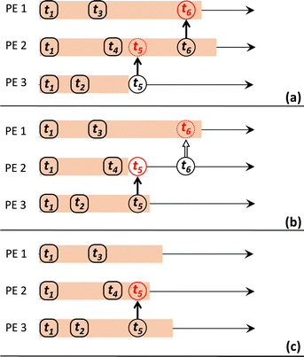
Complications arise when the time-stamp, tmessage, of a message received by a PE is less than the current KMC time in its subdomain, i.e. the message instructs the PE to execute an event in the past. This constitutes a violation of causality, which can only be resolved by ‘rolling back’ in time25 and re-simulating KMC history. Furthermore, ‘un-doing’ previously executed boundary events and simulating new ones in the process of ‘correcting’ the history of the affected subdomain might trigger further violations (conflicts), which in turn might give rise to even more, and so on. Thus, the worst-case scenario involves a cascade of conflicts that propagates throughout the entire lattice.31
To make it feasible for the PEs to deal with this on a local level (i.e., avoiding the need for global synchronisation), snapshots of the local KMC state are saved by each PE to a state queue (stateQueue) at regular intervals of δsnap KMC steps. This state-saving is a core component of the Time-Warp algorithm, as it enables a PE to roll-back to a KMC state with time-stamp tstate < tconflictmessage (where tconflictmessage corresponds to the message that triggered the conflict). Any messages that were sent by the PE after tconflictmessage are no longer valid and must be undone by sending corresponding ‘anti-messages’, which instruct PEs to delete the invalid messages from their message queues.25 The PE can then begin ‘rollback propagation’, which re-simulates the original KMC timeline until tconflictmessage, at which point the pertinent (conflict-triggering) message can finally be acted upon.31 The key elements of the Time-Warp algorithm are illustrated in Fig. 1.
Note that, if one was able to save KMC state snapshots after every KMC event, no rollback propagation would be necessary. However, this is infeasible in practice; KMC states are saved after several KMC events, and thus, having a saved KMC snapshot available just before the conflict-triggering message is typically unlikely. Note also that, when a rollback occurs in Zacros, the entire state of the simulation is restored, including the adjustable parameter δsnap (see the discussion of stateQueue sparsification in Section 4.1).
The snapshots of the system saved to each stateQueue can occupy large amounts of memory and may need to be accessed frequently, so it is pertinent to consider the most appropriate data structure for this purpose. Currently, linked list and vector data structures are implemented in Zacros. In the linked list, the nodes (‘kmc_state’ objects) are not necessarily stored contiguously in memory, rather each node points (‘links’) to the next in the sequence. This means that memory can be allocated and deallocated as needed each time a snapshot is saved or deleted. In contrast, the vector has a fixed number of slots in a one-dimensional array of type ‘kmc_state’, plus an additional one-dimensional array for indexing purposes. The memory thus needs to be allocated once and for all at the start of the simulation.
Whichever data structure is chosen, to avoid exhausting the memory available, it is also important to have a robust protocol by which PEs can delete any snapshots that are no longer needed. This leads naturally to the concept of global virtual time (GVT), tglob, which is defined as the minimum among all the KMC times and time-stamps of buffered messages (i.e., those sent but not yet acted upon) across all PEs.25 On each PE, the earliest KMC state that could need to be reinstated to restore causality is the last one saved such that its time-stamp tstate = tGVTstate− satisfies tGVTstate− < tglob. All those with tstate < tGVTstate− are obsolete can be safely deleted. Likewise, any obsolete messages may be deleted from messgQueue. In practice, tglob is calculated by means of a global communication event at regular clock-time intervals of ΔτGVT. Knowledge of tglob is also used to decide when to terminate the simulation.31
3 Details of benchmarks
Having discussed the main features and procedures of the implementation of Time-Warp within GT-KMC, we now proceed to discuss the performance benchmarks thereof.3.1 Systems studied
The present benchmarks focused on three systems. Physically, Systems 1 and 2 are highly idealised and differ only in the factor responsible for coupling between subdomains. As described in ref. 31, System 1 models reversible CO adsorption on a square lattice, with one site per unit cell. The adsorbed CO molecules, CO*, do not interact with one another and are allowed to diffuse between nearest-neighbour sites. The elementary steps involved are: | (2) |
 | (3) |
| System | k ads (s−1) | k des (s−1) | k diff (s−1) | ε site (eV) | ε CO* (eV) |
|---|---|---|---|---|---|
| 1 | 1.0 | 1.0 | 10.0 | 0.0 | 0.0 |
| 2 | 1.0 | 1.0 | 0.0 | 0.0 | 0.1 |
Our final system is based on the ‘Brusselator’ model of chemical oscillations41 and entails the following elementary steps:42
 | (4) |
 | (5) |
 | (6) |
 | (7) |
 | (8) |
 | (9) |
| Rate constant | Value (s−1) |
|---|---|
| k Xads | 0.7 |
| k Xdes | k Xads/0.91 |
| k 1 | 9.0 |
| k −1 | 0.6 |
| k 2 | 3.8 |
| k Xdiff | 400.0 |
| k Ydiff | 4.0 |
| k XYdiff | 400.0 |
3.2 Simulation details
Our choice of performance metric is the elapsed clock time per unit of KMC time, | (10) |
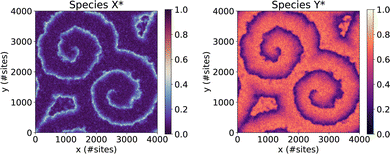 | ||
| Fig. 2 Initial state of System 4, showing the coverages of species X* and Y* exhibiting a pair of well-developed spirals. | ||
All simulations contributing to the performance benchmarks were carried out on Thomas (https://www.rc.ucl.ac.uk/docs/Clusters/Thomas/), a UK National Tier 2 High Performance Computing Hub in Materials and Molecular Modelling, which is a CPU-based computational cluster. Each computational node contains 24 CPU cores (2 × 12-core Intel Xeon E5-2650 v4) and 128 GB RAM.
4 Results and discussion
4.1 System 1
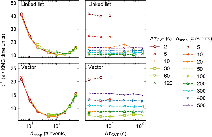
In Fig. 3 and 4, we plot the elapsed clock time per unit of KMC-time, τ*, for System 1 against δsnap (left) and ΔτGVT (right), for two different lattice sizes: 200 × 200 and 1200 × 1200. Note that the left-hand and right-hand plots for each stateQueue data structure contain the same data, only presented differently. Comparing the two figures, one sees that the performance is worse in general (τ* larger) for the larger lattice size. As discussed in ref. 31, this is because the conflict resolution overhead becomes more significant when there are more subdomain boundaries.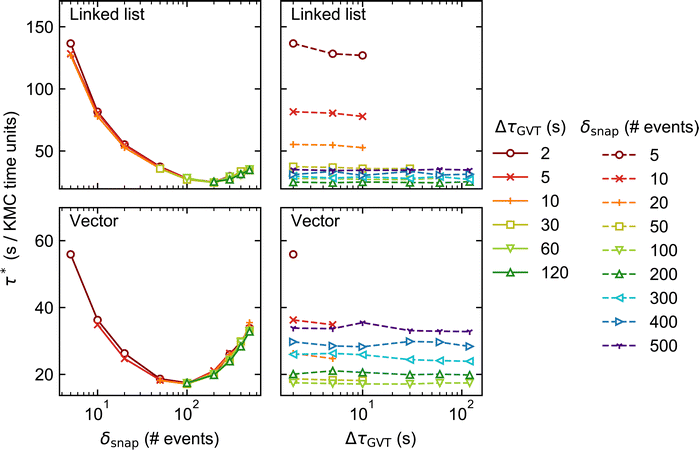 | ||
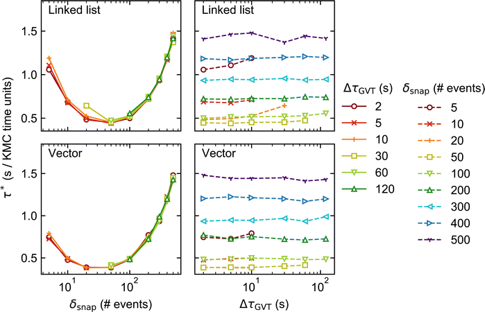
| Fig. 4 As in Fig. 3 but for lattice size 1200 × 1200 (distributed over 144 processors). | ||
Moving on to our discussion of the tunable parameters, our first observation is that faster KMC-time advancement is achieved with the vector data structure than with the linked list. This is true for both lattice sizes and over the full set of values of δsnap and ΔτGVT. It can be attributed to the additional time spent allocating and deallocating memory to stateQueue when the linked list is employed. In contrast, the size of the vector structure is fixed and all its needed memory allocated only once, at the beginning of the simulation.
Unsurprisingly, the performance of each KMC simulation is seen to depend strongly on δsnap. Naively, one may expect a monotonic improvement in performance as δsnap is reduced, since this reduces the total amount of time spent in rollback propagation. However, the performance is observed to improve only up to a point, upon reducing δsnap. In fact, we observe optimum performance (i.e., miminum τ*) around δsnap = 100 when using the vector stateQueue data structure, and slightly higher for the linked list. The sharp rise in τ* for smaller values of δsnap is attributed to the additional time spent saving and deleting snapshots, which constitute the simulation bottleneck in this regime.
On the other hand, the choice of ΔτGVT hardly affects the overall performance, indicating that the global communication overhead is negligible. That said, one should refrain from choosing absurdly small values of ΔτGVT lest the simulation output files occupy vast quantities of disk space.|| One must also ensure that, for a given choice of δsnap, ΔτGVT is sufficiently small such that obsolete snapshots are deleted before the memory allocated to stateQueue is filled up. This is exemplified by the several ‘missing’ data points in Fig. 3 and 4, e.g. all points for which δsnap = 5, ΔτGVT > 10 (ΔτGVT > 5) are absent with the linked list (vector) stateQueue structure in Fig. 3. A data point is omitted wherever stateQueue in at least one PE became too large to fit in the available memory before the allocated 1 hour of clock time had passed.
It is important to stress that the missing data points just described do not imply failed simulations. This is because, when memory does fill up, Zacros is configured to ‘sparsify’ stateQueue by deleting every second snapshot. The frequency with which future KMC states are saved is correspondingly reduced by doubling δsnap. This sparsification procedure can occur, in principle, arbitrarily many times on each PE, such that a poorly chosen input (initial) value for δsnap will not result in simulation failure. In Systems 1 and 2, we found that sparsification tended to occur either permanently** throughout most of the PEs, or not at all. This behaviour can be attributed to the spatial homogeneity of the dynamics, with the upshot that τ* for such simulations is not truly reflective of the input δsnap value, since the latter changes during the run. Thus, we opted to omit the results of any simulations during which sparsification of stateQueue occurred.
4.2 System 2
Fig. 5 and 6 show how the KMC simulation performance for System 2 varies with δsnap and ΔτGVT. Comparing with Fig. 3 and 4, we see that τ* is typically smaller for System 2 than for System 1 by more than an order of magnitude. This is consistent with the absence of CO* diffusion in System 2, which for System 1 is fast and therefore constitutes the vast majority of events in the process queue (see Table 1). Thus, the KMC time advances faster for System 2, even if the rate of event execution is comparable.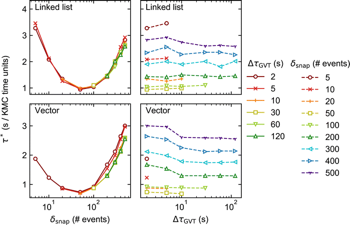 | ||
| Fig. 6 As in Fig. 5 but for lattice size 1200 × 1200 (distributed over 144 processors). | ||
Aside from this, the behaviour of System 2 as a function of δsnap, ΔτGVT, and stateQueue data structure is broadly similar to that of System 1. This suggests that the main sources of computational effort in the Time-Warp algorithm are independent of whether conflicts arise during event execution (System 1) or energetics calculation (System 2). The optimal δsnap values are slightly smaller for System 2, at around 50 across both lattice sizes and stateQueue data structures, which could be indicative of a greater proportion of KMC time having been spent in rollback propagation.
4.3 System 4
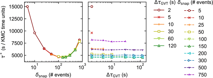
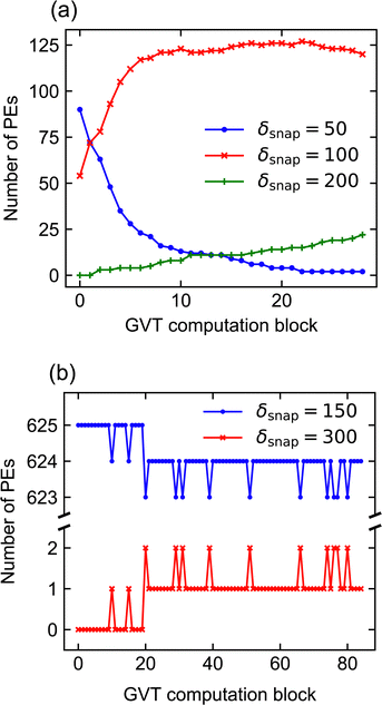
As noted in Section 3, System 4 differs greatly from Systems 1 and 2 in its chemical characteristics. The production of Y* from X*, followed by the autocatalytic regeneration of X*, leads locally to oscillations in the coverage of each species. Coupled with slow versus fast surface diffusion for X* versus Y*, respectively, as well as appropriate initial conditions, these oscillations manifest as rotating spiral waves spanning the entire simulated domain. The dynamics are thus highly spatially inhomogeneous, such that each subdomain exhibits a qualitatively different coverage pattern at any given time. In this context, a robust scheme for conflict resolution at the boundaries is essential if one is to capture the propagation of the spiral wavefronts accurately, since the characteristic wavelength of the pattern exceeds the size of the subdomains.In spite of these differences, our performance benchmarks paint a broadly similar picture for System 4 (Fig. 7) as for Systems 1 and 2. Optimal performance is obtained with δsnap ≃ 150, while the choice of ΔτGVT has little overall effect. In contrast to Systems 1 and 2, we have not indiscriminately omitted data points for which sparsification occurred; due to the spatial inhomogeneity, stateQueue can be sparsified in a small fraction of the 625 processors without significantly affecting the overall performance. In fact, such isolated sparsifications are often found to be reversed by subsequent rollbacks. This is illustrated in Fig. 8, which shows how δsnap varied with clock time during selected simulations of Systems 2 and 4. The ‘missing’ data points in Fig. 7 correspond to (δsnap, ΔτGVT) values for which large-scale sparsification was to be expected based on the predicted memory requirements.
5 Conclusions
We have built on the work of Ravipati et al.31 to understand how the performance of distributed on-lattice KMC, facilitated by Jefferson's Time-Warp algorithm,25 depends on the treatment of state snapshot saving during the simulation. In particular, we were interested in how overall performance is affected by the frequency of saving events, quantified by the state saving interval δsnap, as well as the global virtual time (GVT) computation interval, ΔτGVT, which determines how often the obsolete snapshots are erased from memory. We also investigated whether a linked list or vector data structure (currently the default in Zacros) is preferable for storing the state queue (stateQueue).Our benchmarks focused on three systems. Systems 1 and 2 are both highly simplified models of reversible CO adsorption, spatially homogeneous and identical except in the factor responsible for coupling between subdomains (diffusion and lateral energetic interactions, respectively). In contrast, System 4 – a lattice-based adaptation of the well-known ‘Brusselator’ model – exhibits complex and large-scale spatiotemporal pattern formation, and is thus an ideal test case for our Time-Warp implementation. For all systems, we found consistently that using a vector data structure to store stateQueue leads to faster KMC propagation than using the linked list, which we attribute to the overhead of allocating and deallocating memory to the latter. We also found, however, that the state saving interval, δsnap is by far the most important tunable parameter in controlling Time-Warp performance. We reasoned that optimising δsnap corresponds to minimising the combined overheads of rollback propagation and that of saving and deleting snapshots. On the other hand, ΔτGVT was seen to have minimal effect on simulation performance, provided it is small enough to prevent the memory allocated to stateQueue from filling up.
Currently in Zacros both δsnap and ΔτGVT are set by the user at the beginning of the simulation. However, if stateQueue runs out of available memory, δsnap is updated dynamically and memory is freed by way of ‘sparsification’, whereby every second snapshot in stateQueue is deleted and δsnap is correspondingly doubled. In the case that the initial value of δsnap is ‘optimal’, i.e. maximises the KMC-time advancement rate, each sparsification event will result in performance degradation for the remainder of the run. A more desirable approach might be to enable dynamic updates also to ΔτGVT such that it can be reduced when stateQueue is seen to be filling up the available memory too quickly. This would be challenging to implement in practice, since, while δsnap is declared locally on each PE (so sparsification is a local operation), ΔτGVT is a global variable. Hence, dynamic optimisation of ΔτGVT would rely on global communication among PEs, which currently only occurs during the GVT computation events themselves.
Some important aspects of performance optimisation remain unaddressed, notably the best way to estimate the optimal MPI configuration (number of PEs) and δsnap value in general (without resorting to extensive benchmarking case-by-case). One should expect the optimal δsnap to decrease as nPE increases in the strong-scaling regime (fixed lattice size), as smaller subdomains will demand less CPU time for saving/deleting snapshots while incurring more frequent boundary conflicts. Preliminary strong-scaling benchmarks of System 4 appear to support this hypothesis. Another issue that we have yet to address fully is load balancing; so far, we have focused on benchmarking systems in which the time-averaged surface coverages are roughly constant across the simulated domain. However, in situations where the coverage is inherently dispersed, the topological restrictions imposed on domain decomposition in Zacros (see Section 2) may inhibit good scaling efficiency. We are considering generalising our code in the future to relax these restrictions. Notwithstanding, the benchmarks presented herein highlight the key principles that should guide Zacros users towards maximising the performance of distributed GT-KMC simulations.
Author contributions
Giannis D. Savva: methodology, software, validation, formal analysis, investigation, data curation, writing – review & editing, visualisation. Raz L. Benson: software, formal analysis, investigation, writing – original draft, writing – review & editing, visualisation. Ilektra-Athanasia Christidi: methodology, software, writing – review & editing, project administration, funding acquisition, supervision. Michail Stamatakis: conceptualisation, methodology, software, validation, investigation, resources, writing – review & editing, visualisation, supervision, project administration, funding acquisition.Conflicts of interest
Our graph-theoretical Kinetic Monte Carlo (GT-KMC) software, Zacros, used for the present study has been commercialised with UCL Business, the technology transfer office of University College London; see https://zacros.org/software.Acknowledgements
This project has received funding from the embedded CSE program of the ARCHER UK National Supercomputing Service (https://www.archer.ac.uk) (project identifiers: eCSE01-001, eCSE10-08, eCSE01-13), the Leverhulme Trust (project RPG-2017-361) and from the European Union's Horizon 2020 research and innovation programme under grant agreement No. 814416. The authors acknowledge the use of the UCL Research Software Development Service (RSD@UCL). The provision of computational resources by the UK Materials and Molecular Modelling Hub (specifically access to HPC facility Thomas), which is partially funded by EPSRC (EP/P020194/1 and EP/T022213/1), is also gratefully acknowledged.Notes and references
- M. Neurock and E. W. Hansen, Comput. Chem. Eng., 1998, 22, S1045 CrossRef CAS.
- K. Reuter and M. Scheffler, Phys. Rev. B: Condens. Matter Mater. Phys., 2006, 73, 045433 CrossRef.
- C. Garcia Cardona, I. Webb, E. Blackburn, G. J. Wagner, V. Tikare, E. A. Holm, S. J. Plimpton, A. P. Thompson, A. Slepoy, X. W. Zhou, C. C. Battaile and M. E. Chandross, Crossing the Mesoscale No-Man's Land via Parallel Kinetic Monte Carlo, Sandia National Laboratories technical report, 2009 Search PubMed.
- K. Reuter, Modeling and Simulation of Heterogeneous Catalytic Reactions, John Wiley and Sons, 2011, ch. 3, pp. 71–111 Search PubMed.
- A. P. J. Jansen, An Introduction to Kinetic Monte Carlo Simulations of Surface Reactions, Springer, 2012 Search PubMed.
- M. Stamatakis and D. G. Vlachos, ACS Catal., 2012, 2, 2648 CrossRef CAS.
- M. Leetmaa and N. V. Skorodumova, Comput. Phys. Commun., 2014, 185, 2340 CrossRef CAS.
- L. Kunz, F. M. Kuhn and O. Deutschmann, J. Chem. Phys., 2015, 143, 044108 CrossRef PubMed.
- M. Stamatakis, J. Phys.: Condens. Matter, 2015, 27, 013001 CrossRef CAS PubMed.
- H. Prats, F. Illas and R. Sayós, Int. J. Quantum Chem., 2018, 118, e25518 CrossRef.
- S. Matera, W. F. Schneider, A. Heyden and A. Savara, ACS Catal., 2019, 9, 6624 CrossRef CAS.
- M. Pineda and M. Stamatakis, J. Chem. Phys., 2022, 156, 120902 CrossRef CAS PubMed.
- H. Eyring, J. Chem. Phys., 1935, 3, 107 CrossRef CAS.
- K. J. Laidler and M. C. King, J. Phys. Chem., 1983, 87, 2657 CrossRef CAS.
- A. A. Gokhale, S. Kandoi, J. P. Greeley, M. Mavrikakis and J. A. Dumesic, Chem. Eng. Sci., 2004, 59, 4679 CrossRef CAS.
- K. A. Fichthorn and W. H. Weinberg, J. Chem. Phys., 1991, 95, 1090 CrossRef CAS.
- D. Frenkel and B. Smit, Understanding Molecular Simulation: From Algorithms to Applications, Academic Press, London, 2nd edn, 2002 Search PubMed.
- G. Ertl, Angew. Chem., Int. Ed., 2008, 47, 3524 CrossRef CAS PubMed.
- S. Nettesheim, A. Vonoertzen, H. H. Rotermund and G. Ertl, J. Chem. Phys., 1993, 98, 9977–9985 CrossRef CAS.
- E. Martínez, J. Marian, M. Kalos and J. Perlado, J. Comput. Phys., 2008, 227, 3804 CrossRef.
- G. Arampatzis, M. A. Katsoulakis, P. Plecháč, M. Taufer and L. Xu, J. Comput. Phys., 2012, 231, 7795 CrossRef.
- Y. Shim and J. G. Amar, Phys. Rev. B: Condens. Matter Mater. Phys., 2005, 71, 125432 CrossRef.
- B. D. Lubachevsky, J. Comput. Phys., 1988, 75, 103 CrossRef.
- R. M. Fujimoto, Parallel and Distributed Simulation Systems, John Wiley and Sons, New York, 2000 Search PubMed.
- D. R. Jefferson, ACM Trans. Program. Lang. Syst., 1985, 7, 404 CrossRef.
- B. D. L. S. G. Eick, A. G. Greenberg and A. Weiss, ACM Trans. Model. Comput. Simul., 1993, 3, 287 CrossRef.
- A. Weiss and B. Lubachevsky, Proceedings of the 15th Workshop on Parallel and Distributed Simulation, Lake Arrowhead, CA, USA, 2001, p. 185.
- Y. Shim and J. G. Amar, Phys. Rev. B: Condens. Matter Mater. Phys., 2005, 71, 115436 CrossRef.
- M. Merrick and K. A. Fichthorn, Phys. Rev. E, 2007, 75, 011606 CrossRef PubMed.
- G. Nandipati, Y. Shim, J. G. Amar, A. Karim, A. Kara, T. S. Rahman and O. Trushin, J. Phys.: Condens. Matter, 2009, 21, 084214 CrossRef PubMed.
- S. Ravipati, G. D. Savva, I.-A. Christidi, R. Guichard, J. Nielsen, R. Réocreux and M. Stamatakis, Comput. Phys. Commun., 2022, 270, 108148 CrossRef CAS.
- M. Stamatakis and D. G. Vlachos, J. Chem. Phys., 2011, 134, 214115 CrossRef PubMed.
- J. Nielsen, M. D'Avezac, J. Hetherington and M. Stamatakis, J. Chem. Phys., 2013, 139, 224706 CrossRef PubMed.
- A. Chatterjee and A. F. Voter, J. Chem. Phys., 2010, 132, 194101 CrossRef PubMed.
- E. C. Dybeck, C. P. Plaisance and M. Neurock, J. Chem. Theory Comput., 2017, 13, 1525 CrossRef CAS PubMed.
- T. Danielson, J. E. Sutton, C. Hin and A. Savara, Comput. Phys. Commun., 2017, 219, 149 CrossRef CAS.
- G. Savva, PhD thesis, University College London, 2022.
- T. Bligaard, J. Nørskov, S. Dahl, J. Matthiesen, C. Christensen and J. Sehested, J. Catal., 2004, 224, 206 CrossRef CAS.
- J. Sanchez, F. Ducastelle and D. Gratias, Physica A, 1984, 128, 334 CrossRef.
- C. Wu, D. Schmidt, C. Wolverton and W. Schneider, J. Catal., 2012, 286, 88 CrossRef CAS.
- I. Prigogine and R. Lefever, J. Chem. Phys., 1968, 48, 1695 CrossRef.
- G. D. Savva, R. L. Benson, I.-A. Christidi and M. Stamatakis, Phil. Trans. R. Soc. A DOI:10.1098/rsta.2022.0235.
Footnotes |
| † Electronic supplementary information (ESI) available: Weak-scaling plots for systems 1 and 2. See DOI: https://doi.org/10.1039/d2cp04424b |
| ‡ These authors contributed equally to this work. |
| § Validation of the Time-Warp implementation is achieved by verifying that it produces results identical to those of a ‘parallel-emulation’ serial algorithm.31 |
| ¶ The internal structure sizes in Zacros have been hand-optimised to make best use of the available memory. A way to automate this is currently under development. |
| || After each GVT computation, Zacros prints information to each of the nPE general_output*.txt files, which consequently would become extremely large if, say, the GVT were computed every 1 s for several hours. See the Zacros User Guide for further details. |
| ** ‘Permanently’ in this context means that δsnap was not subsequently reverted to its input value by means of a rollback. |
| This journal is © the Owner Societies 2023 |

