Deep-red electro-fluorescence based on an excimer emission with hot-exciton channels†
Ying
Gao‡
a,
Mingming
Yao‡
b,
Changjiang
Zhou
c,
Haichao
Liu
a,
Shi-Tong
Zhang
*a and
Bing
Yang
 *a
*a
aState Key Lab of Supramolecular Structure and Material, Institute of Theoretical Chemistry, College of Chemistry, Jilin University, Changchun, P. R. China. E-mail: stzhang@jlu.edu.cn; yangbing@jlu.edu.cn
bJilin OLED Material Tech Co. Ltd, Changchun, P. R. China
cCollege of Chemical Engineering, Zhejiang University of Technology, Hangzhou, P. R. China
First published on 16th December 2021
Abstract
Red and deep-red fluorescent materials are broadly applied in many fields, such as organic light emitting diodes (OLEDs), biological imaging and night-vision devices. In this work, we designed and synthesized two orange to red emissive donor–acceptor (D–A) materials, DMAC-NZP and DMAC-NZC, in which DMAC-NZC possesses an extra cyano group. The DMAC-NZC aggregate demonstrates a large red-shift of 60 nm compared with DMAC-NZP, which can be assigned to the formation of discrete dimer and excimer emissions in its single crystal and neat films, respectively, upon cyano-substitution. Both DMAC-NZC and DMAC-NZP exhibit a maximum external quantum efficiency (EQEmax) of over 4% and a very small efficiency roll-off in doped OLEDs. More importantly, the non-doped OLEDs of DMAC-NZC show deep-red electrofluorescence at 688 nm with a considerably high exciton utilization efficiency (EUE) of 55%–82%. This work not only gives a new functional group for the construction of deep-red pure organic efficient excimer materials, but also further verifies that the “hot exciton” theory can also be effective in the excimer-based OLEDs.
Introduction
Red and deep-red fluorescent materials have received tremendous scientific and commercial attention over the last few decades, owing to their applications in organic light-emitting diodes (OLEDs), biological imaging, night-vision devices and so forth.1–6 Generally, constructing the donor–acceptor structure and extending π-conjugation are the most frequently applied approaches to achieve red fluorescent materials.7,8 However, high-efficiency red light-emitting materials are still rare compared with green and blue emissive materials due to the resonance of the vibrational wave function of the excited state and the ground state, which may accelerate the non-radiative transitions and cause a low photoluminescence quantum yield (PLQY). Another commonly used approach to realize largely red-shifted emission is the intermolecular aggregation, especially the π–π interaction. However, it is still important to prevent the aggregation caused quenching (ACQ) that causes a bad decrease of the PLQY. Overall, it is still challenging to pave the way for realizing efficient red-emissive materials and their aggregates.Despite the fact that the aggregates, especially the excimer and exciplex, that are used are believed to be of low-efficiencies, recently, our group have reported a series of highly efficient excimer fluorescent materials.9–11 For example, with systematically regulated side-group substitutions, the optimized structure 2-(anthracen-9-yl) thianthrene (2-TA-AN) exhibits a green excimer emission at 526 nm with a considerably high PLQY of 80% compared with its deep-blue, but low-efficiency monomer emission (424 nm, PLQY = 33%).12 However, the present excimer is that the molecular structure of these efficient excimers is limited to anthracene derivatives, which can only produce a green emission. To date, there are almost no reports on the structures of efficient red-emissive excimers, let alone electroluminescence based on red-emissive excimers.
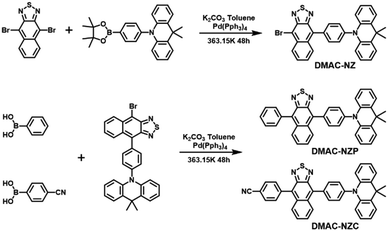
In this work, we reported two red-emissive donor–acceptor materials DMAC-NZC and DMAC-NZP using 9,9-dimethyl-10-phenyl-9,10-dihydroacridine (DMAC) and naphtho[2,3-c][1,2,5]thiadiazole (NZ) as donor and acceptor moieties, respectively (Scheme 1).13 Compared to DMAC-NZP, an extra cyano-group is involved in DMAC-NZC, which forms a pair of hydrogen bonds as the “interlock” of two adjacent DMAC-NZC molecules, generating typical discrete dimers with a large red-shift compared with the DMAC-NZC monomer (66 nm) and the DMAC-NZP aggregate (60 nm). The non-doped OLED of DMAC-NZC demonstrates deep-red electroluminescence (EL) at 688 nm with a maximum external quantum efficiency (EQEmax) of 0.7%, corresponding to a Commission International de I’Eclairage (CIE) of (0.65, 0.34). More importantly, cyano-substitution also contributes to the reduced OLED rolling-off from DMAC-NZC (7%) to DMAC-NZP (18%), revealing the potential of deep-red, pure-organic excimer-emission OLEDs.14,15
 | ||
| Scheme 1 Structures and syntheses of DMAC-NZC and DMAC-NZP. Detailed synthesis processes and characterization data are shown in the ESI† (Fig. S14–S19). | ||
Results and discussion
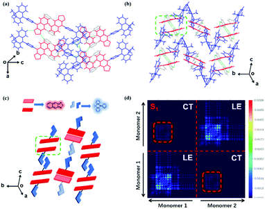
The normalized absorption and photoluminescence (PL) spectra of DMAC-NZC and DMAC-NZP in different solvents are shown in Fig. 1. The absorption bands of DMAC-NZC and DMAC-NZP are all in the range of 375–550 nm, displaying broadband absorption that can be assigned to the intramolecular charge-transfer (CT) transition from the donor DMAC to the acceptor NZ unit, which is the key necessity of the possible efficient triplet-to-singlet reverse intersystem crossing (RISC) process for OLEDs. Futher proof for the formation of strong CT characteristics is that, in Fig. 1b, different from the typical solvatochromic PL spectra of the molecular CT structure, an obvious “blue-shift” can be observed in acetonitrile solutions of the two materials, which is essentially combined by the visible LE and the largely red-shifted, poorly quenched pure CT emission of the dual-emission caused by high solvent polarity.16–18 Additionally, the diluted solutions, neat films and doped films of DMAC-NZC and DMAC-NZP all exhibit single-exponential PL decay, indicating that both of the two materials are not of traditional TADF properties (Table S1, ESI†).Notably, although it seems that the introduction of the cyano-group does not make much difference to the DMAC-NZC and DMAC-NZP monomer emissions (diluted solutions and the doped films), the aggregates of DMAC-NZC and DMAC-NZP demonstrate quite different emission behaviours, including the light-colour and PLQY (Fig. 1b, c and Table 1). The neat powder and the single crystal of DMAC-NZC show a larger red-shift of near 60 nm compared with DMAC-NZP, which is in favour of better red purity. It should be noticed again that the aggregation in DMAC-NZC does not produce dual-emissions as in the large polarity solvents, which gives possibility for the fabrication of the non-doped deep-red OLEDs and, more importantly, implies that, distinguishing from DMAC-NZP and other CT or hybrid locally excited and charge-transfer (HLCT) materials, the large red-shift of the DMAC-NZC aggregate is not induced by polar circumstances.19–22 The molecular structures and packing modes of their single crystals can illustrate the structural reason why DMAC-NZC can demonstrate better red purity. As shown in Fig. 2, the DMAC-NZC single crystal mainly contains a face-to-face dimeric stacking between two NZ moieties with a π-overlap of 61% (Fig. S13b, ESI†). Such a large π-overlap in face-to-face dimeric stacking of NZ units manifest a strong π–π interaction, which contributes to the largely red-shifted fluorescence of DMAC-NZC. Furthermore, the cyano-group makes great contributions to the formation of the face-to-face dimer. In Fig. 2, the intermolecular C–H⋯N interactions can serve as the “interlock” of two adjacent DMAC-NZC molecules and form discrete dimers in the whole crystal, making a stable red-shifted emission. In comparison, this regularly arranged dimer cannot be found in DMAC-NZP; instead, only C–H⋯π interactions can be found in its crystal structure, which is the reason why there is a density matrix (TDM) of the S1 excited state of DMAC-NZC using the Multiwfn package.23 In Fig. 2d, it can be observed that the interchange (or intermolecular CT) exists in the S1 excited state of DMAC-NZC, which is an obvious indicator of the excimer formation. Additionally, it should be noted that due to the substitution of the electron donor, the lifetime of the DMAC-NZC crystal is even shorter than its dispersed film (Table S1, ESI†), which is quite different to the traditional excimer emissions and more suitable for the fabrication of a non-doped OLED.
| Materials/PLQY (%) | Powder | Crystal | 5% Doped film in PMMA |
|---|---|---|---|
| DMAC-NZC | 4.3 | 3.2 | 71 |
| DMAC-NZP | 35 | 5.7 | 75 |
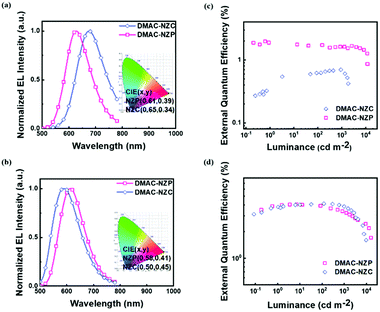
The two materials both possess satisfactory thermal stabilities of > 120 °C glass transition temperature (Tg) and > 350 °C thermal deposition temperature (Td), which enable their further application in electroluminescence (EL) (Fig. S4 and S5, ESI†). Moreover, the thermal stability of DMAC-NZC is better than that of DMAC-NZP, owing to the introduction of the cyano-group and stronger intermolecular interactions. The non-doped OLED performances of the two materials are summarized in Table 2. In particular, the OLED based on DMAC-NZC shows deep-red EL at 688 nm, corresponding to a Commission International de I’Eclairage (CIE) coordinate of (0.65, 0.34), implying that the EL of the non-doped OLED of DMAC-NZC is originated from the excimer emission of its neat film (Fig. 3a). More importantly, it is worth noting that the efficiency rolling-off of both the doped and non-doped OLEDs based on DMAC-NZC are only near 7%, proving that the cyano-group substitution not only exhibits an obvious red-shift by the effective dimer formation, but also increases the stability of the films and OLEDs (Table 2).
| Emitter | V on(V) | λ EL (nm) | CEmax (cd A−1) | PEmax (lm W−1) | CIE (x,y) | EQEmax/EQE100/EQE1000(%) | Max luminance (cd m−2) | Roll-off (%) | PLQY (%) | EUE (%) |
|---|---|---|---|---|---|---|---|---|---|---|
| V on: turn-on voltage; λEL: electro-luminous wavelength; CEmax: maximum luminous efficiency; PEmax: maximum power efficiency; CIE: Commission International de I’Eclairage (CIE) coordinate; EQEmax/EQE100/EQE1000: maximum external quantum efficiency/EQE at 100 (cd m−2) luminance/EQE at 1000 (cd m−2); rolling-off: rolling-off = (EQEmax − EQE1000)/EQEmax; EUE: EQE = (γ × EUE × ΦPL) × ηout, where γ is the recombination efficiency of the injected electron and hole (generally identified as 100%); ΦPL is the PLQY of the emitter; ηout is the light out-coupling fraction, which is estimated as a range of 20%–30% for the glass substrates. | ||||||||||
| NZC | 3.1 | 688 | 0.32 | 0.16 | 0.65,0.34 | 0.70/0.62/0.65 | 1859 | 7.1 | 4.2 | 55–83 |
| NZP | 3.3 | 628 | 2.5 | 2.5 | 0.61,0.39 | 2.0/1.7/1.6 | 11![[thin space (1/6-em)]](https://www.rsc.org/images/entities/char_2009.gif) 790 790 |
18 | 9.2 | 66–99 |
| NZC (doped) | 3.8 | 588 | 9.2 | 6.9 | 0.50,0.45 | 4.1/4.1/3.8 | 9612 | 7.1 | 47 | 29–44 |
| NZP (doped) | 3.2 | 612 | 6.9 | 6.8 | 0.58,0.41 | 4.0/3.9/3.4 | 15![[thin space (1/6-em)]](https://www.rsc.org/images/entities/char_2009.gif) 820 820 |
17 | 28 | 47–71 |
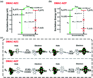
Last but not least, the exciton utilization efficiencies (EUEs) of both the doped and non-doped OLEDs of DMAC-NZC and DMAC-NZP are all far superior compared to the 25% spin-statistics limit even if the light-out-coupling efficiencies (ηout) of the glass substrate OLEDs are estimated as an upper limit of 30%, matching well with the “hot-exciton” model (Fig. 4 and Fig. S8, ESI†). We carried out density functional theory (DFT) and time-dependent DFT (TDDFT) calculations to demonstrate the mechanism of the exceeding EUEs of the two materials. As shown in Fig. 4a and b, the energy diagram of the two materials demonstrates the typical “hot-exciton” model, which should meet three typical demands:24–36
 | ||
| Fig. 4 Molecular simulation on the excited states of DMAC-NZC and DMAC-NZP. (a) The excitation energy level of DMAC-NZC. (b) The excitation energy level of DMAC-NZP. (c) The NTO of the S2 and T2 excited states of DMAC-NZC and the NTO of the S2 and T2 excited states of DMAC-NZP. The DFT and TDDFT calculations are carried out using the Gaussian 09 D. 01 package using the hybrid function m062x under the 6-31g(d,p) level.37–40 | ||
(1) A large energy gap between T2 and T1 for forbidden internal conversion from T2 to T1.
(2) The CT excited state properties of T2 and S2, and a small energy gap for efficient reverse intersystem crossing (RISC).
(3) Considerable spin–orbit coupling (SOC) of T2 and S2 can also help boost the “hot-exciton” channel.
In Fig. 4, for the occasion of DMAC-NZC and DMAC-NZP, first, they both possess large T1 and T2 excited state energy gaps, which can block the internal conversion processes. Secondly, they both possess a small T2–S2 energy splitting, which can increase the RISC rate from T2 to S2. Next, both for DMAC-NZC and DMAC-NZP, the natural transition orbitals (NTOs) of the S2 and T2 excited states show apparent CT state properties with separated hole and electron wave functions (Fig. 4c). Last but not least, the SOC rates between the T2 and S2 excited states of DMAC-NZC and DMAC-NZP are estimated as 0.2109 cm−1 and 0.1792 cm−1, respectively. These values are seemingly smaller than those of the metallic complexes or some room-temperature-phosphorescent organic materials that contain heavy atoms, but they can also afford efficient RISC according to the reported studies.41–45 More importantly, the DMAC-NZC dimer can well inherit both the “hot-exciton” energy structure and the characteristic NTO of its monomer, which is identical to its boosting EUE of the non-doped OLED.
Conclusions
In summary, we adapt the cyano-group as an auxiliary acceptor to further improve the color purity of red-emissive NZ based D–A derivatives. The cyano-substituted material DMAC-NZC demonstrates deep-red, excimer induced EL in the non-doped OLED, which is of 60 nm red-shift compared to the non-substituted DMAC-NZP. The structural reason that DMAC-NZC possesses largely red-shifted emission can be assigned to its discrete dimer formation, in which two C–H⋯N interactions between the cyano-group and the phenyl ring on the adjacent monomer serve as the interlocks. More importantly, the cyano-group is a conjugative electron donating moiety, which can also improve the PLQY. In addition, photophysical characterization and theoretical calculations suggest that DMAC-NZC and DMAC-NZP are both HLCT materials with the “hot exciton” RISC channel, which contributes to high PLQYs and high exciton utilization in OLEDs. Overall, the introduction of the cyano-group could be an effective method to design the next-generation of cheaper, easily synthesized red and deep-red electro-fluorescent excimer materials.Author contributions
Ying Gao: Data curation, formal analysis, and writing – original draft. Mingming Yao: Data curation, formal analysis, and writing – original draft. Ying Gao and Mingming Yao contributed equally. Changjiang Zhou: Data curation, formal analysis, and writing – original draft. Haichao Liu: Data curation, formal analysis, and writing – original draft. Shi-Tong Zhang: Conceptualization, formal analysis, funding acquisition, writing – original draft, writing – review and editing, and supervision. Bing Yang: Funding acquisition, writing – review and editing, and supervision.Conflicts of interest
The authors declare that they have no known competing financial interests or personal relationships that could have appeared to influence the work reported in this paper.Acknowledgements
This work was supported by the National Natural Science Foundation of China (51803071, 51903031 and 91833304), the National Basic Research Program of China (2016YFB0401001) and the JLUSTIRT (2019TD-33).Notes and references
- N. Alifu, A. Zebibula, J. Qi, H. Zhang, C. Sun, X. Yu, D. Xue, J. W. Y. Lam, G. Li, J. Qian and B. Z. Tang, ACS Nano, 2018, 12, 11282–11293 CrossRef CAS PubMed.
- W. Ge, Y. Xu, C. Liu, W. Xu, Y. Zhang, W. Si, W. Zhao, C. Ou and X. Dong, J. Mater. Chem. B, 2021, 9, 8300–8307 RSC.
- Z. He, Y. Gao, H. Zhang, Y. Xue, F. Meng and L. Luo, Adv. Healthcare Mater., 2021, e2101056, DOI:10.1002/adhm.202101056.
- Z. Sheng, B. Guo, D. Hu, S. Xu, W. Wu, W. H. Liew, K. Yao, J. Jiang, C. Liu, H. Zheng and B. Liu, Adv. Mater., 2018, e1800766, DOI:10.1002/adma.201800766.
- Q. Wan, R. Zhang, Z. Zhuang, Y. Li, Y. Huang, Z. Wang, W. Zhang, J. Hou and B. Z. Tang, Adv. Funct. Mater., 2020, 30, 2002057 CrossRef CAS.
- S. Zhu, S. Herraiz, J. Yue, M. Zhang, H. Wan, Q. Yang, Z. Ma, Y. Wang, J. He, A. L. Antaris, Y. Zhong, S. Diao, Y. Feng, Y. Zhou, K. Yu, G. Hong, Y. Liang, A. J. Hsueh and H. Dai, Adv. Mater., 2018, 30, e1705799 CrossRef PubMed.
- Y. Shen, Z. Zhang, H. Liu, Y. Yan, S. Zhang, B. Yang and Y. Ma, J. Phys. Chem. C, 2019, 123, 13047–13056 CrossRef CAS.
- B. Situ, M. Gao, X. He, S. Li, B. He, F. Guo, C. Kang, S. Liu, L. Yang, M. Jiang, Y. Hu, B. Z. Tang and L. Zheng, Mater. Horiz., 2019, 6, 546–553 RSC.
- W. Jiang, Y. Shen, Y. Ge, C. Zhou, Y. Wen, H. Liu, H. Liu, S. Zhang, P. Lu and B. Yang, J. Mater. Chem. C, 2020, 8, 3367–3373 RSC.
- H. Liu, Y. Shen, Y. Yan, C. Zhou, S. Zhang, B. Li, L. Ye and B. Yang, Adv. Funct. Mater., 2019, 29, 1901895 CrossRef.
- Q. Luo, L. Li, H. Ma, C. Lv, X. Jiang, X. Gu, Z. An, B. Zou, C. Zhang and Y. Zhang, Chem. Sci., 2020, 11, 6020–6025 RSC.
- H. Liu, Y. Gu, Y. Dai, K. Wang, S. Zhang, G. Chen, B. Zou and B. Yang, J. Am. Chem. Soc., 2020, 142, 1153–1158 CrossRef CAS PubMed.
- T. Liu, L. Zhu, C. Zhong, G. Xie, S. Gong, J. Fang, D. Ma and C. Yang, Adv. Funct. Mater., 2017, 27, 1606384 CrossRef.
- A. Sharma, K. R. J. Thomas, K. K. Kesavan, I. Siddiqui, M. Ram Nagar and J.-H. Jou, ACS Appl. Electron. Mater., 2021, 3, 3876–3888 CrossRef CAS.
- D. G. Congrave, B. H. Drummond, P. J. Conaghan, H. Francis, S. T. E. Jones, C. P. Grey, N. C. Greenham, D. Credgington and H. Bronstein, J. Am. Chem. Soc., 2019, 141, 18390–18394 CrossRef CAS PubMed.
- X. Tang, X.-L. Li, H. Liu, Y. Gao, Y. Shen, S. Zhang, P. Lu, B. Yang, S.-J. Su and Y. Ma, Dyes Pigm., 2018, 149, 430–436 CrossRef CAS.
- M. Wang, Z. Cheng, X. Meng, Y. Gao, X. Yang, H. Liu, S.-T. Zhang, H. Ma and B. Yang, Dyes Pigm., 2020, 177, 108317 CrossRef CAS.
- S. Xiao, S.-T. Zhang, Y. Gao, X. Yang, H. Liu, W. Li and B. Yang, Dyes Pigm., 2021, 193, 109482 CrossRef CAS.
- J. Fan, Y. Zhang, K. Zhang, J. Liu, G. Jiang, F. Li, L. Lin and C.-K. Wang, J. Mater. Chem. C, 2019, 7, 8874–8887 RSC.
- J. Jiang, X. Li, M. Hanif, J. Zhou, D. Hu, S. Su, Z. Xie, Y. Gao, B. Yang and Y. Ma, J. Mater. Chem. C, 2017, 5, 11053–11058 RSC.
- S.-Y. Yang, Y.-L. Zhang, A. Khan, Y.-J. Yu, S. Kumar, Z.-Q. Jiang and L.-S. Liao, J. Mater. Chem. C, 2020, 8, 3079–3087 RSC.
- Y. Zhang, X. Zhou, C. Zhou, Q. Su, S. Chen, J. Song and W.-Y. Wong, J. Mater. Chem. C, 2020, 8, 6851–6860 RSC.
- T. Lu and F. Chen, J. Comput. Chem., 2012, 33, 580–592 CrossRef CAS PubMed.
- W. Li, Y. Pan, R. Xiao, Q. Peng, S. Zhang, D. Ma, F. Li, F. Shen, Y. Wang, B. Yang and Y. Ma, Adv. Funct. Mater., 2014, 24, 1609–1614 CrossRef CAS.
- C. Lin, P. Han, S. Xiao, F. Qu, J. Yao, X. Qiao, D. Yang, Y. Dai, Q. Sun, D. Hu, A. Qin, Y. Ma, B. Z. Tang and D. Ma, Adv. Funct. Mater., 2021, 31, 2106912 CrossRef CAS.
- J. Liu, Z. Li, T. Hu, X. Wei, R. Wang, X. Hu, Y. Liu, Y. Yi, Y. Yamada-Takamura, Y. Wang and P. Wang, Adv. Opt. Mater., 2018, 1801190, DOI:10.1002/adom.201801190.
- T. Liu, L. Zhu, S. Gong, C. Zhong, G. Xie, E. Mao, J. Fang, D. Ma and C. Yang, Adv. Opt. Mater., 2017, 5, 1700145 CrossRef.
- X. Lv, L. Xu, W. Cui, Y. Yu, H. Zhou, M. Cang, Q. Sun, Y. Pan, Y. Xu, D. Hu, S. Xue and W. Yang, ACS Appl. Mater. Interfaces, 2021, 13, 970–980 CrossRef CAS PubMed.
- Y. Pan, W. Li, S. Zhang, L. Yao, C. Gu, H. Xu, B. Yang and Y. Ma, Adv. Opt. Mater., 2014, 2, 510–515 CrossRef CAS.
- Q. Wan, B. Zhang, Y. Ma, Z. Wang, T. Zhang and B. Z. Tang, J. Mater. Chem. C, 2020, 8, 14146–14154 RSC.
- C. Wang, X. Li, Y. Pan, S. Zhang, L. Yao, Q. Bai, W. Li, P. Lu, B. Yang, S. Su and Y. Ma, ACS Appl. Mater. Interfaces, 2016, 8, 3041–3049 CrossRef CAS PubMed.
- C. Wang, X.-L. Li, Y. Gao, L. Wang, S. Zhang, L. Zhao, P. Lu, B. Yang, S.-J. Su and Y. Ma, Adv. Opt. Mater., 2017, 5, 1700441 CrossRef.
- W. Xie, B. Li, X. Cai, M. Li, Z. Qiao, X. Tang, K. Liu, C. Gu, Y. Ma and S. J. Su, Front. Chem., 2019, 7, 276 CrossRef CAS PubMed.
- Y. Xu, P. Xu, D. Hu and Y. Ma, Chem. Soc. Rev., 2021, 50, 1030–1069 RSC.
- L. Yao, B. Yang and Y. Ma, Sci. China: Chem., 2014, 57, 335–345 CrossRef CAS.
- Y. Zheng, X. Zhu, Z. Ni, X. Wang, Z. Zhong, X. J. Feng, Z. Zhao and H. Lu, Adv. Opt. Mater., 2021, 9, 2100965 CrossRef CAS.
- Z. D. Li, B. B. Suo, Y. Zhang, Y. L. Xiao and W. J. Liu, Mol. Phys., 2013, 111, 3741–3755 CrossRef CAS.
- Z. D. Li, Y. L. Xiao and W. J. Liu, J. Chem. Phys., 2012, 137, S10–S16 Search PubMed.
- Z. D. Li, Y. L. Xiao and W. J. Liu, J. Chem. Phys., 2014, 141, 16–27 Search PubMed.
- W. J. Liu, F. Wang and L. M. Li, J. Theor. Comput. Chem., 2003, 2, 257–272 CrossRef CAS.
- F. B. Dias, T. J. Penfold and A. P. Monkman, Methods Appl. Fluoresc., 2017, 5, 012001 CrossRef PubMed.
- H. Liu, L. Yao, B. Li, X. Chen, Y. Gao, S. Zhang, W. Li, P. Lu, B. Yang and Y. Ma, Chem. Commun., 2016, 52, 7356–7359 RSC.
- P. K. Samanta, D. Kim, V. Coropceanu and J. L. Bredas, J. Am. Chem. Soc., 2017, 139, 4042–4051 CrossRef CAS PubMed.
- C. Zhou, S. Zhang, Y. Gao, H. Liu, T. Shan, X. Liang, B. Yang and Y. Ma, Adv. Funct. Mater., 2018, 28, 1802407 CrossRef.
- H. J. Kim, H. Kang, J. E. Jeong, S. H. Park, C. W. Koh, C. W. Kim, H. Y. Woo, M. J. Cho, S. Park and D. H. Choi, Adv. Funct. Mater., 2021, 31, 2102588 CrossRef CAS.
Footnotes |
| † Electronic supplementary information (ESI) available. CCDC 2115526 and 2115527. For ESI and crystallographic data in CIF or other electronic format see DOI: 10.1039/d1tc04920h |
| ‡ Co-authors. |
| This journal is © The Royal Society of Chemistry 2022 |


