Emerging investigator series: photocatalytic membrane reactors: fundamentals and advances in preparation and application in wastewater treatment
Andrew
Ashley
a,
Brandon
Thrope
 b,
Mahbubhoor R.
Choudhury
*a and
Alexandre H.
Pinto
 *b
*b
aDepartment of Civil and Environmental Engineering, Manhattan College, 4513 Manhattan College Parkway, Riverdale, NY 10471, USA. E-mail: mahbuboor.choudhury@manhattan.edu
bDepartment of Chemistry and Biochemistry, Manhattan College, 4513 Manhattan College Parkway, Riverdale, NY 10471, USA. E-mail: alex.pinto@manhattan.edu
First published on 7th October 2021
Abstract
Photocatalytic membrane reactors (PMRs) are a promising treatment technology for degradation of organic compounds discharged from wastewater treatment facilities. This review presents information about TiO2 nanoparticles, which are the widely used photocatalyst semiconductor in PMRs, and how doping can be used to make TiO2 able to absorb part of the visible spectrum. Then, many examples are presented showing PMR applications for various feedwater types ranging from dyes, oils, pharmaceuticals, and antibiotic resistant bacteria, either in simulated wastewater or water from real matrices. Although the results are dependent on the feed, photocatalyst, and type of reactor, the PMR technology can achieve removal efficiency higher than 95% for some situations. PMRs have also shown antimicrobial properties in removing 99.9% of antibiotic-resistant bacteria in one study presented. Additionally, PMRs have demonstrated antifouling properties due to their surface modification – resulting in their reuse and extended lifespan. Although photocatalytic membrane reactors can achieve quantitative removal in some feed water types, more development is needed before employing them for more widespread wastewater treatment. In this sense, the article ends with a perspective section where some possible advances in the photocatalyst and reactor design are suggested which can expand the range of PMR applications.
Water impactPhotocatalytic membrane reactors (PMRs) can efficiently degrade organic compounds in wastewater and in water from different real matrices. They also demonstrated anti-microbial properties in treating wastewater with antibiotic-resistant bacteria. An added benefit of PMRs was that surface modification of the membranes caused anti-fouling/self-cleaning properties, which allowed for membrane reuse and extended lifespan. |
Introduction
The world's population is experiencing a rapid growth rate. Currently, there are 7.9 billion people living worldwide, and this number is expected to be approximately 10 billion people by the year 2050.1 An increase in population creates an increased demand for water resources due to growing urbanization and agricultural development, continued industrialization, and other demands. Increased water use results in a corresponding increase in wastewater production, as pharmaceutical, food, pesticide, textile, and finishing industries produce a large volume of discharge effluents. These effluents may contain contaminants not completely treated by conventional wastewater resource recovery facilities (WRRFs). Different categories may comprise these contaminants, such as pharmaceuticals, persistent organic pollutants, and organic dyes.2 Some of these pollutants have been ubiquitously discovered in groundwater, surface water, and municipal sewage treatment plants.3 The WRRF effluents have generally been treated by physicochemical, oxidative, or, most commonly activated biochemical sludge processes; however, these treatment technologies also produce secondary pollutants by introducing chemicals or the possible accumulation of other bio-resistant species.4 In recent years, many researchers have investigated treatment technologies for these wastewater pollutants in response to the stated concerns.Extensive efforts have been devoted to developing advanced removal technologies for these pervasive and bio-resistant pollutants in wastewater. The technologies considered include adsorption, photodegradation, and membrane separation, with membrane filtration being considered as a promising technology given its low energy consumption and high efficacy in wastewater treatment.5 The drawback of conventional membrane separation processes is the deposition of contaminants such as proteins and microorganisms, which block the membrane surface and pores – thus, resulting in membrane fouling.5 Advanced oxidative processes (AOPs) have also been proven as a promising removal technology for pollutants not otherwise readily removed by conventional treatment technologies. AOPs are aqueous phase oxidation technologies that use highly reactive intermediate species such as (primarily, but not exclusively) hydroxyl radicals (OH˙) to destroy targeted pollutants.6 AOPs have experienced immense research and development, particularly because of the diversity of technologies involved and potential application areas.6 The use of photocatalysis as one of the AOPs has been growing rapidly, as it is known as an environmentally friendly, sustainable, and energy-saving technology that can be applied to low biodegradability, high complexity, and high concentration pollutants in wastewater.3 The photocatalyst harnesses energy from a UV, visible, or solar irradiation source in the water to produce strong oxidants that degrade persistent organic pollutants present in the water.
Photocatalytic AOPs can be coupled with membrane filtration processes to produce a photocatalytic membrane reactor (PMR), which accumulates pollutants near the catalyst surface, followed by photocatalytic degradation of the pollutants. The pairing of the two technologies can be easily integrated because they have similar operation conditions, making the system easy to control.3 A PMR uses membrane filtration to separate pollutants in the water and allows for the rejected pollutants to be decomposed via photocatalysis – resulting in the added benefit of alleviating membrane fouling by creating a self-cleaning membrane.7 Most PMRs use a combination of photocatalysis and pressure-driven membrane processes, such as microfiltration (MF), nanofiltration (NF), and ultrafiltration (UF).
In this review article, the research done so far is presented to focus on photocatalytic membrane filtration. This was done by assessing PMRs from different wastewater feeds and pollutant types. The photocatalyst type and features are presented, emphasizing the structural properties of TiO2 nanomaterials, as well as how TiO2 can be modified via doping to change its light absorption properties. Then, the membrane fabrication processes were evaluated including the operational conditions that resulted in optimal pollutant removal. Finally, the paper presents examples of PMR applications to real matrices, followed by a discussion regarding the drawbacks and potential for future PMR technologies and applications.
Photocatalysis
Theory of photocatalytic degradation
Photocatalysts are substances that accelerate the rate of chemical reactions upon exposure to irradiation, usually by a light source. The irradiated photocatalyst reacts with oxygen (O2), water (H2O), and hydroxyl groups (OH−) to generate reactive oxygen species (ROS) such as hydroxyl radicals (OH˙) and superoxide radical anions (O2˙−) – these are all strong oxidants.3 These reactive radicals are the major oxidizing species responsible for degrading the organic pollutants in wastewater to produce carbon dioxide (CO2) and water. Fig. 1 demonstrates the photocatalytic degradation mechanism using irradiation energy from a light source.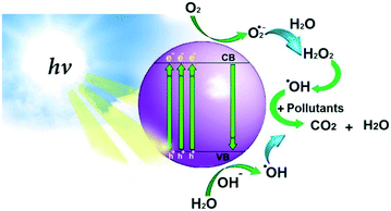 | ||
| Fig. 1 Scheme of the photocatalytic degradation mechanism. Reprinted with permission of ref. 8. Copyright 2021©Elsevier. | ||
Upon irradiation, the photocatalyst is activated, and electrons are transferred from the valence band (VB) to the conduction band (CB). At the conduction band, electrons are released and bond with oxygen to yield superoxide radical anions (O2˙−). The surface of the photocatalyst at the valence band is positively charged and takes electrons from water to create hydroxyl radicals (OH˙).
Decreasing the energy gap (i.e. energy band gap – Eg) between the VB and CB of the photocatalyst allows for higher photocatalytic activity and better absorption ability of visible light or natural sunlight.3 In addition to the photocatalyst type, the efficiency of the photocatalysis is affected by the light source irradiation – energy from the irradiation should be equal to or greater than the energy band gap of the photocatalyst.8 This indicates that there is a direct relationship between irradiation intensity and photocatalysis efficiency since a higher irradiation intensity results in more efficient photocatalysis reactions.8
There are two classifications of photocatalysis: homogenous and heterogeneous. These classifications are based on the appearance of the physical state of the reactants.2 Homogeneous photocatalysis has the photocatalyst in the same phase (i.e., solid, liquid, or gas) as the reactants. Homogenous photocatalysis produces free radicals by illuminating light over the homogenous molecules of oxidizing agents such as ozone (O3) and hydrogen peroxide (H2O2) – with common homogenous photocatalysis including ozonation and photo-Fenton processes, UV/H2O2, and UV/H2O2/O3.2
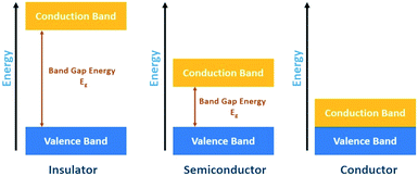
In heterogeneous photocatalysis, however, the photocatalysts are entirely separate from (usually dispersed in) the reactants and are usually made of a semiconductor material (i.e., metal oxides) because semiconductors are capable of absorbing light to facilitate the transfer of the electron, which results in the production of reactive species.2Fig. 2 shows the three basic categories of materials and demonstrates how the energy band gap between the valence and conduction bands varies across insulators, conductors, and semiconductors.
The band gap energy between the valence and conduction band in insulators is too large and prevents the transfer of electrons from the VB to the CB. The gap energy in semiconductors is narrower and can facilitate the movement of electrons to the conduction band. However, for metals/conductors, there is no energy gap, and electrons can freely move between the VB and CB. This review article focuses on using heterogenous semiconductor photocatalysis coupled with membrane processes – photocatalytic membrane reactors (PMRs).
TiO2: the photocatalyst and its structural and optical features
One important component of the photocatalytic membranes is the photocatalyst material. This photocatalyst is a semiconductor that will absorb energy, usually in the UV or visible range of the electromagnetic spectrum. When the photon absorbed has energy equal to or higher than the band gap of that semiconductor, electrons are promoted from the valence band to the conduction band. Consequently, a hole is created in the valence band. The electron–hole pair creation can lead to a series of reactions that can degrade the pollutant molecules present in the water.9Titanium dioxide (TiO2) is the semiconductor photocatalyst commonly used in the composition of photocatalytic membranes, mainly due to its chemical stability, strong oxidation ability, non-toxicity, low price, and transparency to visible light.10
Titanium dioxide (TiO2) is an n-type semiconductor found in nature in three crystalline phases: rutile (tetragonal), anatase (tetragonal), and brookite (orthorhombic).11 The three polymorphs have direct band gap energy values equal to 3.0 eV for rutile, 3.4 eV for anatase, and 3.3 eV for brookite.12 The unit cells of the three crystalline phases are shown in Fig. 3.
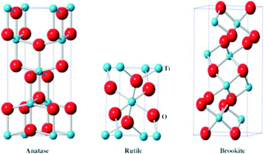 | ||
| Fig. 3 Unit cell representations of TiO2 anatase (left), rutile (center), and brookite (right). Reprinted with permission of ref. 13. Copyright 2015©Elsevier. | ||
Rutile is the thermodynamically stable phase at the bulk size scale, and many studies have revealed that rutile transformation to anatase or brookite is irreversible.14 In this sense, anatase and brookite are considered metastable phases in the bulk regime.14 However, in the nanoparticle regime, the anatase phase is usually stabilized depending on the synthesis method and conditions. The higher stability of the anatase phase on the nanoscale is attributed to its lower surface energy compared to the surface energy values of the rutile and brookite.15 Pure brookite is the rarest and most difficult natural TiO2 polymorph to obtain under laboratory conditions. Consequently, there are fewer studies in the literature for this polymorph compared to the rutile and anatase ones.16
The TiO2 applications are very dependent on the polymorph present in the material. For instance, rutile is commonly used in inks, paint, fillers, sunscreen, and makeup pigments.17 Anatase is the polymorph widely used as a photocatalyst semiconductor in environmental remediation processes to eliminate pollutant molecules from water. Density functional theory (DFT) studies indicated that the highest photocatalytic activity of anatase compared to rutile and brookite can be correlated to a longer lifetime of the photoexcited electron–hole pair18 and also to a lighter electron–hole pair effective mass in comparison to the ones for rutile and brookite. This lighter effective mass facilitates the migration of the electron–hole pair from the interior to the surface of TiO2, making the electron–hole pair recombination more difficult.18
TiO2 photocatalysis mechanism
When TiO2 absorbs energy equal to or higher than its band gap energy, an electron is promoted to the conduction band (ecb−), whereas a hole is generated in the valence band (hvb+). As long as the electron–hole separation stands, they can migrate separately to the TiO2 surface. Once on the TiO2 surface, hvb+ can react with surface-bound H2O or OH− to produce the hydroxyl radical (OH˙). Meanwhile, the ecb− in the TiO2 surface can react with O2 to produce the superoxide anion radical (O2˙−).19 The mechanism of OH˙ and O2˙− radical production can be summarized by eqn (1)–(3):19| TiO2 + hν → ecb− + hvb+ | (1) |
| O2 + ecb− → O2˙− | (2) |
| H2O + hvb+ → OH˙ | (3) |
O2˙− can react with H+ from the water and produce the HO2˙ radical, cascading further reactions producing H2O2 and OH˙:20
| O2˙− + H+ → HO2˙ | (4) |
| HO2˙ + HO2˙ → H2O2 + O2 | (5) |
| ecb− + H2O2 → OH˙ + OH− | (6) |
| O2˙− + H2O2 → OH˙ + OH− + O2 | (7) |
| H2O2 + hν → 2OH˙ | (8) |
Then, the pollutant organic molecules are degraded by reacting with OH˙, hvb+, or ecb−:20
| Organic molecule + OH˙ → Degradation Products | (9) |
| Organic molecule + hvb+ → Oxidation Products | (10) |
| Organic molecule + ecb− → Reduction Products | (11) |
Several factors affect the efficiency of the photocatalytic oxidation process of titanium dioxide. Suspending the catalyst directly in solution generally has better results than fixing it on a carrier material.20 In terms of dosage of the photocatalyst, there is an optimum dosage in which decreasing it would lead to a decreased activity due to a loss of surface area. From this optimal dosage, increasing the dosage would also lead to a decrease in activity due to effects related to higher solution opacity, decreased light intensity reaching the catalyst, and agglomeration of the surface molecules leading to a reduced surface area.20
The light intensity is also an important factor regarding the TiO2 photocatalysis kinetics. For instance, at low light intensities (below 0–20 mW cm−2), the reaction rate is first order in relation to the light intensity because the rate of electron–hole photogeneration is higher than the rate of electron–hole recombination. At intermediate intensities, around 25 mW cm−2, the reaction rate is half-order in relation to light intensity because the rates of electron–hole photogeneration and electron–hole recombination are comparable. Meanwhile at high light intensity, the rate is zeroth order, as it does not depend on the light intensity, The reason why the rate does not depend on the light intensity is because the electron transfer from the TiO2 to the O2 producing O2˙− is the rate-determining step.20
The interplay between the solution pH and TiO2 isoelectric point (IEP) is another factor that influences TiO2 photocatalysis kinetics. For instance, for pH values lower than the IEP, the TiO2 surface will be positively charged and thus more prone to have negatively charged species adsorbed onto the TiO2 surface. Comparatively, if the pH values are higher than the IEP, the TiO2 surface will be negatively charged and thus more prone to have positively charged species adsorbed onto the TiO2 surface.20
Visible-light absorbing TiO2
Industrially speaking, the TiO2 widely used is TiO2 Evonik Aeroxide P25®, formerly known as Degussa P25. Thorough X-ray diffraction characterization revealed that TiO2 P25 is composed of approximately 76.3% anatase, 10.6% rutile, and 13.0% in amorphous content, by weight,21 and has a band gap energy value around 3.15 eV, which corresponds to maximum absorption of photons with a wavelength around 390 nm, thus, in the UV-A portion of the electromagnetic spectrum.22In fact, only a small portion of solar radiation is ultraviolet light (UV; λ < 400 nm); specifically, 5% of the total solar irradiation is in the UV region, while 43% is in the visible region. The remaining solar radiation is composed of light in the infrared region, with wavelengths greater than 750 nm.23–25
In this sense, it is necessary to figure out ways that can make TiO2 able to absorb visible light by narrowing its band gap energy, in order to take advantage of a higher portion of the solar irradiance spectrum. One possible way to lower the TiO2 band gap is by doping it with other metallic or non-metallic ions. So, this section presents some methods and results in improving the TiO2 visible light activity using doping methods. The studies are focused on the TiO2 photocatalyst in the nanomaterial form, not necessarily incorporated to the PMR. We understand that some of the examples presented will never be able to be applied in a real PMR application because of factors like cost or toxicity. However, those examples are still important as they help to envision the depth of the scientific field.
TiO2 metal ion doping
Murakami and co-workers doped TiO2 with the following first-row transition metal ions: Fe3+, Cu2+, Ni2+, and Cr3+.26 For all the metallic ions, the band gap energy is correlated with the order of redox potential: Fe3+ > Cu2+ > Ni2+ > Cr3+. Furthermore, Fe3+ showed significantly higher CO2 evolution and had a higher oxidizing ability than the other metallic ions, which are favorable characteristics. The metallic ions excite an electron that is transferred to the conduction band of TiO2, reducing Ti4+ to Ti3+. Thus, TiO2 receives electrons in the conduction band at higher wavelengths than would be achieved with undoped TiO2.Besides the first-row transition metal ions V5+, Fe3+, Ni2+, Zn2+, and Mn2+, Devi and co-workers studied TiO2 doping with heavier ions such as Os3+ and Ru3+.27 They observed that the inverse of the electronegativity of the transition metals formed a positive linear relationship with the band gap absorption in the resulting metal-doped TiO2 photocatalyst. The relationship is meaningful, and the resulting enhancements of the modified photocatalysts proceed in the following order, from the most to the least effective: Os3+ ∼ Ru3+ > Fe3+ ∼ Ni2+ > Zn2+ ∼ Mn2+ ∼ V5+. Pure TiO2 responds to UV light through the electronic excitation of an O 2p level electron to the Ti 3d level band. By doping TiO2 with transition metal ions, the d–d transition can be enhanced because an excited electron from the valence band in the metal is transferred to the conduction band of TiO2.27 Interestingly, each of the doped samples exhibited optimal activity at a dopant concentration of 0.06 at%; the one exception, Ni2+-TiO2, showed optimal activity at 0.08 at%. Enhanced visible light absorption does not directly relate to a great photocatalytic efficiency for the degradation of organic pollutants. For example, Mn2+-TiO2 showed a weaker red-shift than most of the other metallic ion doped TiO2 samples, but it had the greatest ability to degrade indigo carmine and 4-nitrophenol.27
Noble metal ions, such as Ag+, Au+, and Pt4+, have also been used to dope TiO2. A decrease in the band gap energy to 2.68 eV was observed for Ag+ doped TiO2. The excited valence band electrons in TiO2 moved to the conduction band in the metal Ag+ ion, and thus a hole was formed in the Ti4+ valence band.28 Similar to Ag+, Au+ doped TiO2 showed enhanced visible light absorption, specifically, with a band gap energy equal to 2.21 eV. The band gap was also dependent on the particle size, with the band gap decreasing with a decrease in the particle size. Au-anatase showed higher photocatalytic activity due to a larger surface area compared to Au-rutile for the degradation of phenol.29 Doping titania with Pt4+ slightly increased the light absorption edge to 410 nm compared to undoped TiO2. The sample that consisted of 92% rutile and 8% anatase phase exhibited the highest efficiency for phenol degradation.30 The introduction of mid-band gap states is due to the excitation of the valence band electrons in TiO2 into the localized conduction band of the Pt4+ ions. These mid-band gap states produced the enhanced visible light absorption.30
Not all metallic ion TiO2 doping accomplishes the band gap energy reduction to the visible light range. For instance, Ta5+ doped TiO2 exhibited a blue shift compared to undoped TiO2. In addition, the degradation of acetone by Ta5+-TiO2 was unchanged compared to the degradative ability of undoped TiO2. Tantalum exhibits minimal benefits when used as a dopant, and thus Ta5+ doped TiO2 is likely not the optimal catalyst for visible light photocatalytic applications.31
The lanthanide series ions La3+, Ce3+, and Gd3+ were studied as individual dopants for TiO2. They exhibited similar band gaps in the respective doped TiO2: La3+ (2.70 eV), Ce3+ (2.64 eV), and Gd3+ (2.76 eV).32 The three types of doped TiO2 presented a higher visible light absorption efficiency than undoped TiO2 due to the higher active surface area and concentration of charge carriers. All three dopants showed enhanced activity for the degradation of dyes than undoped TiO2. This enhancement can be attributed to (1) the introduction of mid band gap energy states, allowing electrons to be promoted to the conduction band of TiO2 at higher wavelengths; (2) the increased surface acidity of the doped catalyst compared to undoped TiO2, attracting, to a greater degree, anionic organic pollutants such as mono azo dyes.32 For the three lanthanide ions studied, the degradation activity increased up to a concentration of 0.15 mol%. Mono azo dyes were degraded faster than the less basic di azo dyes due to differences in acid–base properties between the dyes.32
Actinide ions have also been used to dope TiO2, aiming to bring the TiO2 band gap closer to the visible region. The thorium ion (Th4+) doped TiO2 showed an increase in the red shift when the atomic concentration of the dopant was increased from 0.02% to 0.06%.33 At higher concentrations of the dopant, a blue shift was observed. Two absorption edges were seen in the visible light region for Th4+-TiO2: 460 nm and 486 nm. The lower absorption edge is due to the charge transfer complex (CTC) formed between the d and f orbitals of the dopant and the TiO2 energy levels, forming a mid-gap energy level. The higher absorption edge at 486 nm is possibly due to the incorporation of Ti3+ into the crystalline lattice.
Additionally, Th4+(0.06%)-TiO2 exhibited good photoactivity in the visible light region to degrade the pesticide chlorpyrifos (CP). In fact, Th4+ doped TiO2 showed higher efficiency to degrade CP than the TiO2 samples that were doped with either V5+ or Mo6+. This is partly due to the large surface area of Th4+(0.06%)-TiO2: 34 m2 g−1. As a result, the complete degradation of CP was achieved in 45 min for the Th4+(0.06%)-TiO2 sample under visible light, while only 10% degradation of the pesticide was achieved for the undoped TiO2 sample.33
TiO2 non-metal ion doping
Non-metal ion doping usually happens by doping TiO2 with ions from the following elements: B, C, N, S, F, P. Non-metal ion doping shifts the TiO2 band gap to the visible range mainly by introducing the dopants to the O2− sites instead of Ti4+ like in metal ion doping.34 Non-metal ion doping produces mid-gap energy levels that can be excited upon visible light absorption. The electron from the mid-gap energy level migrates to the TiO2 conduction band, leaving a hole in the mid-gap energy level. These electron and hole can migrate to the TiO2 surface and participate in redox reactions involving reactive oxygen species, like the reaction shown in eqn (2), (3), (10) and (11).34Boron-doped TiO2 (B-TiO2) was synthesized by a solvothermal method in ethanol using boric acid as the boron source.35 The samples were prepared with varying amounts of boron, ranging from 1 to 8% in weight. All the samples formed phase-pure anatase, and the band gap decreased from 3.09 eV for the undoped TiO2 to 2.89 eV for 8% B-TiO2. All the samples were used as photocatalysts to degrade the pollutant molecules bisphenol A, dichlorophenol, ibuprofen, and flurbiprofen, under visible and UV light, separately. Both for UV and visible light, for all pollutant molecules, the degradation rate increased with increasing boron percentage in B-TiO2.35
C-Doped TiO2 was prepared by incorporating carbonate-like species into TiO2, using a combination of hydrothermal and calcination steps. The sample calcined at 200 °C presented the highest band gap narrowing, producing a band gap of 2.89 eV. The same sample presented better visible-light photocatalytic degradation than TiO2 P25 for the pollutant molecules methyl orange, rhodamine B, methylene blue, and 4-chlorophenol.36
N-Doped TiO2 nanotubes were prepared by anodic oxidation and then annealed in an N2 atmosphere. N doping did not alter the TiO2 nanotube morphology, but it changed the absorption edge from the UV range for the undoped TiO2 to the visible range for the N-doped TiO2 nanotubes. The N-doped TiO2 presented higher degradation rates for the insecticide acephate than the undoped TiO2 under sunlight.37
Bakar et al. prepared S-doped TiO2 by anionic and cationic doping modes.38 In S-cationic doping, S6+ replaced Ti4+. Meanwhile for S-anionic doping, S2− replaced O2−. S doping did not cause substantial changes in the crystalline structure or morphology compared to the TiO2 ones. However, the optical properties were changed by S doping. For instance, the undoped TiO2 had a band gap energy of around 3.09 eV, whereas the cationic and anionic S-doped TiO2 presented a band gap around 2.85 and 2.82 eV, for a quantity of 3%, in moles, sulfur doping. Both types of S-doped TiO2 nanomaterials were used to degrade phenol and methyl orange excited by visible light (λ = 440 nm) and present degradation efficiency values higher than 80%. In contrast, the undoped TiO2 degraded only about 5% of the pollutant's initial concentration.38 The cationic and anionic S-doped TiO2 followed different mechanisms to produce the reactive oxygen species. The cationic S-doped TiO2 relied on the production of OH˙ due to the hole created in the valence band. Contrastingly, the anionic S-doped TiO2 relied on OH˙ production in a mid-gap state closer to the TiO2 valence band, and O2˙− in a mid-gap state closer to the TiO2 conduction band, as it can be seen in Fig. 4.38
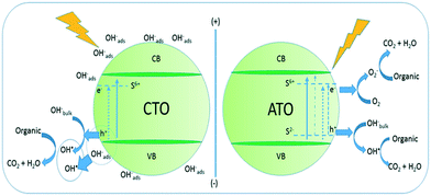 | ||
| Fig. 4 Scheme of reactive oxygen species production and methyl orange degradation by cationic (left) and anionic (right) doped-TiO2. Reprinted with permission of ref. 38. Copyright 2016©Elsevier. | ||
Interestingly, some papers in the literature show the inability of F− ions to narrow the band gap of undoped TiO2.39,40 In one of these papers, the authors used a sol–gel method having trifluoroacetic acid as the fluoride source. They prepared F-TiO2 samples ranging from 1 to 5% F−, in moles.40 The undoped TiO2 was a mixture of anatase and rutile, while the F-TiO2 samples were all phase pure anatase. The undoped TiO2 sample had an indirect band gap of 2.7 eV, whereas all the F-TiO2 samples had band gap energies equal to or higher than 3.0 eV. This fact indicated that F− ion doping actually enhanced light absorption in the UV range, instead of in the visible range. All the samples were used to degrade the pesticide atrazine under UV and visible light. The pseudo-first-order rate constant for the photocatalytic degradation process increased up to the F-TiO2 sample containing 4% F−, when the process is carried out under UV light. In contrast, the pseudo-first-order rate constant for the photocatalytic degradation process decreased up to the F−TiO2 sample containing 4% F−, when the process is carried out under visible light. The photocatalytic degradation results confirmed that F− doping enhanced UV light absorption and decreased visible light absorption.
Phosphorus doped TiO2 with surface oxygen vacancies (P-TiO2) had photocatalytic activity to degrade the antibiotic ciprofloxacin when illuminated by visible light.41 P-TiO2 with surface oxygen vacancies exhibited a band gap around 3.02 eV, whereas TiO2 had a band gap around 3.17 eV. To quantitatively confirm the higher activity of the P-TiO2 photocatalytic degradation under visible light than TiO2, the pseudo-first-order rate constant for the degradation using P-TiO2 was about 16.2 times higher than the one for TiO2.41
When Si4+ is used as a dopant, the Si-TiO2 band gap increased compared to the undoped TiO2 band gap.42 Thus, Si4+ does not show any enhanced visible light absorption but can show enhanced photocatalytic degradation under UV light compared to undoped TiO2. Si-TiO2 exhibited enhanced the degradation of the wood preservative pentachlorophenol in the UV region due to the doped compound possessing: (1) super-hydrophilicity, leading to a high concentration of OH˙ radicals adsorbing on the catalyst surface, (2) high thermal stability, and (3) good surface wettability.42
Not only ions from second and third-period elements from the periodic table work as non-metal dopants for TiO2, from the fifth period of the periodic table, I5+ ion doped TiO2 enhanced the light absorption in the visible region compared to undoped TiO2; specifically, the band edge was located at 505 nm (2.45 eV). A large concentration of Ti3+ sites is produced due to I5+ substituting Ti4+ on the catalyst surface. The increased photoactivity for the degradation of phenol is due to the relative decrease in electron–hole recombination compared to undoped TiO2.43
Photocatalytic membrane reactors
A photocatalytic membrane reactor (PMR) is a system coupling photocatalysis and membrane filtration to produce high-quality permeate.3 Photocatalysis creates strong oxidizing radicals that degrade the pollutant. At the same time, a membrane is utilized to separate the substrate molecules present and act as a barrier for photocatalyst loss – this allows for reuse.3 The PMR has two main photocatalytic configurations as seen in Fig. 5; (A) PMR with a suspended photocatalyst and (B) PMR with an immobilized photocatalyst.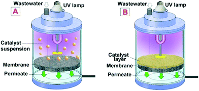 | ||
| Fig. 5 PMR representation: A) (left) with a suspended (slurried) photocatalyst; B) (right) with an immobilized photocatalyst. Reprinted with permission of ref. 8. Copyright 2021©Elsevier. | ||
In the slurried PMR, the photocatalyst destroys the organic pollutant, while the membrane has multiple roles of confining the pollutant, photocatalysts, and degradation intermediates into the reaction environment.44 The PMR with a suspended photocatalyst has a larger active surface area of the catalyst in suspension, which allows for good contact between the pollutant and catalyst which further results in higher photocatalytic efficiency compared to the immobilized configuration. However, the penetration of light through the suspended PMR is reduced if the catalyst concentration is too high – resulting in light scattering. As a result, catalyst dosing is the most critical parameter for the suspended PMR. Another drawback is that suspended PMRs are prone to membrane fouling caused by the photocatalyst nanoparticles (NPs) being deposited onto the membrane surface which results in flux decline, light scattering, and diminishes the performance of the suspended PMR.44
Photocatalytic membrane reactors with the catalyst immobilized on the membrane allow photocatalysis and separation to be carried out by the same singular unit. This configuration allows for easy recovery of the catalyst, reuse, and regeneration. Additionally, the fouling is mitigated due to the photocatalytic membrane's self-cleaning properties, which results in better performance and higher permeate quality. Immobilized PMRs also have reduced light scattering. However, the immobilized catalyst in PMRs has reduced photoactivity due to the reduced surface area of the catalyst in contact with the pollutant. Therefore, the focus of this section is immobilized photocatalytic membrane reactors.
On the membrane side of an immobilized photocatalyst PMR, the immobilization is achieved by coating the photocatalysts on top of the membranes or blending the photocatalysts on the membrane matrix (polymeric or ceramic), or synthesizing the membrane out of a pure photocatalyst material.45 The reactor configuration can vary in terms of the location/type of light source and feed flow scheme.
The following paragraphs briefly discuss the coupling of different membrane-based technologies in the PMRs:
(i) Pressure-driven membranes for PMRs: these reactors include pressure-driven membrane-based processes like microfiltration (MF), ultrafiltration (UF), or nanofiltration (NF) combined with the photocatalysts in the reactor (either slurried or immobilized on the membrane matrix).46–48 These are the most commonly studied PMRs, where a transmembrane pressure difference is maintained by applying pressure from the feed side46 or maintaining a vacuum on the permeate side (submerged membrane).47 An increase in transmembrane pressure will lead to the deposition of foulants on the membrane surface and the formation of a cake layer. For immobilized photocatalyst PMRs, organic foulants are expected to oxidize on the membrane surface and eventually reduce the cake formation impact. However, for slurried PMRs, the photocatalysts in suspension will also deposit on the cake layer and lower the permeate flux.
(ii) Membrane distillation (MD) coupled in PMRs: MD is a thermally induced vapor pressure-driven membrane-based process that can achieve 100% rejection of all non-volatile constituents from the feed water.49 MD uses a microporous hydrophobic membrane that prevents water flow through the membrane but allows the water vapor to flow from the feed side to the permeate side. The water vapor later condensates on the permeate side and is taken out for disposal, treatment, or reuse purposes.49 MD in wastewater treatment reduces membrane fouling propensity compared to pressure-driven membrane processes.49 As a result, the PMRs will operate for a longer time duration with higher efficiency. The coupling of MD in the PMR has demonstrated superior organic dye removal efficiencies.50 However, the process lacks the rejection capabilities for volatile organic compounds.
(iii) Dialysis coupled in PMRs: dialysis achieves separation of solutes from the feed side by the relative difference in diffusion through a semipermeable membrane. Coupling of dialysis in a PMR involves using a dialysis membrane to separate a recirculating feed stream from a recirculating permeate stream. In the case of a slurried reactor, the permeate stream will contain the photoreactive catalysts in it. It will pass through a separate photocatalytic reactor containing a light source in it.51,52
Several parameters affect the performance of PMRs. Whether dead-end or cross-flow, the operational mode can significantly affect the efficiency of the photocatalytic membrane. When in the dead-end mode, the substrate is retained and accumulates on the membrane surface, forming a cake layer that results in reduced photocatalytic efficiency due to reduced permeability and photocatalytic performance.44 In the cross-flow mode, the feed flows tangentially to the membrane, removing deposited particles on the surface – thus also reducing fouling.44 The cross-flow mode is ideal for PMRs. The photocatalyst immobilization must also be considered because the three main types (or subcategories) have varying drawbacks. PMRs where the photocatalyst is coated on the membrane by dip-coating, electro-spraying, etc. have reduced membrane permeability and are prone to photocatalyst leaching during operation.44
Photocatalytic irradiation can also affect the performance, and there are multiple forms of irradiation, including light, ultrasonic wave, and heat. This review will further focus on light irradiation in the ultraviolet and visible wavelength spectra. The rate of photocatalytic reactions is directly related to the irradiation intensity. For photocatalytic reactions, artificial lamps with high photon flux are commonly used and can be used in immersed or external configurations.44
The feed characteristics also play a role in photocatalytic performance. The pH of the feed, temperature, presence of inorganic ions, and concentration of pollutants all affect the performance of the system. There is a direct relationship between the substrate concentration and the reaction rate, as the photocatalytic activity increases with increased concentration until the feed becomes too cloudy – causing light scattering and reduced activity.44 The pH affects the adsorption of the substrate on the active sites of the photocatalyst, the desorption of the products, and the permeation of solutes across the membrane.44 PMRs should be operated in the temperature range of 20–80 °C for optimal performance. Lower temperatures decrease the photoactivity because the desorption of the photodegradation products from the surface of the photocatalyst becomes the limiting step.44 Higher temperatures are favorable conditions for electron–hole recombination which also reduces the photocatalytic efficiency.44 Chloride, nitrate, sulfate, carbonate and bicarbonate anions in the feedwater can scavenge the electron–hole pair and hydroxyl radical, thus reducing the photoactivity.44 The flow rate over and across the photocatalytic membrane is also a key operational parameter as it determines the contact time between the photocatalyst and the pollutant – this will ultimately influence degradation.44
Immobilized photocatalytic membrane reactors
Membrane fabrication/modification
The ideal membrane for photocatalytic activity should have several properties, including high selectivity, high stability under reaction conditions, low cost and non-toxicity. The intended use of the membrane will influence the membrane fabrication/modification. A major concern in the design of photocatalytic membranes is the mechanical, chemical and thermal stability under reaction conditions. Selectivity and permeability must also be considered, as these transport properties can be tailored by selecting the appropriate membrane structure and composition.44 It is critical that the process of immobilizing the photocatalyst on the membrane preserves the photoactivity. The membrane support is also a crucial design consideration in preparing PMRs, and these can be organic, inorganic, or metallic.Polymeric membranes are the most commonly used form of organic membrane support and these include polyamide, polyurethane (PU), polyvinylidene fluoride (PVDF), polytetrafluoroethylene (PTFE), polyethersulfone (PES), and polyacrylonitrile (PAN).44 The organic membrane surfaces are susceptible to abrasion from the mechanical action of the particles suspended in the water, as well as damage by irradiation and oxidizing radicals; as a result, inorganic ceramic membranes are good alternatives because of their excellent chemical, thermal and mechanical stability.44 However, ceramic membranes have a higher manufacturing cost compared to polymeric ones. In preparing photocatalytic membranes, the technique used and conditions will be determined by the membrane material and the desired morphology and structure. The preparation techniques available include coating, phase separation, interfacial polymerization, track-etching, sintering, and stretching.44
Coating techniques are the most widely employed methods for the fabrication of immobilized photocatalytic membranes. This method can include spray coating, sol–gel dip coating, and vacuum coating. Significant leaching of NPs has been observed in spray coating and vacuum coating.44 The sol–gel method for fabrication is achieved by coating a colloidal solution (sol) on the membrane followed by drying, and this coating method can be optimized for immobilization and limit the loss of photocatalytic activity.44 Sputtering of photocatalyst particles is another form of membrane fabrication. After the photocatalyst is sputtered on the membrane, followed by anodization and crystallization at mild temperature (<120 °C), the membrane has increased photoactivity due to the enhanced surface area and increased light-harvesting capabilities.44 The deposition of gas-phase photocatalyst nanoparticles is another fabrication technique that gives an increased reaction rate; however, the drawbacks of this technique are photocatalyst leaching and diminution of membrane permeability due to the decreased membrane resistance.44 PVDF polymeric membranes are the most widely used membranes for blended fabrication. These fabricated photocatalytic membranes have the catalyst blended into the membrane matrix, which reduces the possibility of leaching.44
Photocatalytic membrane reactor performance
Carbohydrate polymers
Lu et al. fabricated a novel, sustainable and robust “Ag@AgCl@MOF-cloth” membrane which consisted of a scaffold of carboxymethylated cotton fiber (CCF) and a photocatalyst of Ag@AgCl@MIL-100(Fe) for the treatment of complex wastewater containing oil and dye.53 The cotton fabric was carboxymethylated followed by the in situ synthesis of the metal–organic framework MIL-100(Fe) crystals on the surface of the CCF.53,54 The Ag@AgCl photocatalyst was then immobilized on the MIL-100(Fe)/CCF structure. The preparation scheme of Ag@AgCl@MIL-100(Fe) is shown in Fig. 6.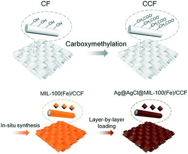 | ||
| Fig. 6 Scheme showing the preparation of the membrane Ag@AgCl@MIL-100(Fe)/CCF. Adapted from ref. 53. Copyright 2020©Elsevier. | ||
The performance of the fabricated membrane was assessed using wastewater containing oil (toluene, cyclohexane and petroleum ether) and dye (rhodamine B and methylene blue) using a feed cross-flow velocity of 5 mL min−1. It was observed that 99% removal was achieved for both dyes and oils, as shown in Fig. 7. The high permeation flux was maintained at a high rate of about 4927 L m−2 h−1 because of the self-cleaning properties of the fabricated membrane when irradiated with visible light, as shown in Fig. 7.53
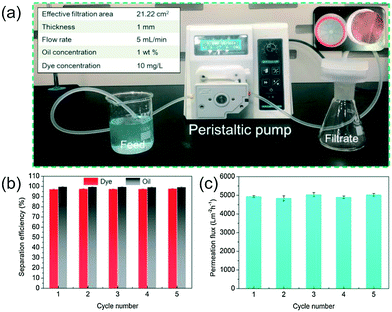 | ||
| Fig. 7 a) A continuous flow system using Ag@AgCl@MIL-100(Fe)/CCF to remove petroleum ether/MB emulsions. The inset shows the top-view of the membrane. (b) Removal efficiency of petroleum ether/MB emulsions in different cycles by visible-light radiation cleaning the used Ag@AgCl@MIL-100(Fe)/CCF membrane. (c) Membrane flux as a function of recycling/reusing. Reprinted from ref. 53. Copyright 2020©Elsevier. | ||
The membrane exhibited high wettability and faster water spreading that resulted in efficient separation. Additionally, this robust membrane can be reused after cleaning with visible light.53
Ceramic-based photocatalytic membranes
A ceramic membrane support was used by Golshenas et al. in the photocatalytic process which was operated in the dead-end mode. A disc-shaped ultrafiltration (UF) ceramic membrane was coated with Al2O3 and then with the TiO2 photocatalyst using the sol–gel method.55 X-ray diffraction (XRD) determined that the membrane was modified with anatase and rutile phases of TiO2; however, it was later determined that the anatase TiO2 enabled the photocatalytic activity.55 TiO2 is a superhydrophilic photocatalyst that resulted in a removal efficiency 97% for 500 ppm oil as a feed, and 96% for 1000 ppm oil as a feed. The removal efficiency was determined by measuring the total organic carbon (TOC) in the feed and the permeate by using a TOC analyzer. It was determined that higher concentrations of oil in the feed resulted in slightly reduced removal efficiency because higher concentrations produced a thicker oil layer hindering UV light from fully diffusing and irradiating the photocatalyst.55 It was determined that transmembrane pressure greater than 1.5 bar and flow rates greater than 32.16 mL min−1 created a denser cake layer in the surface of the membrane – inevitably causing diminished photoactivity and membrane fouling.55 Further study was recommended using the cross-flow mode.Photocatalytic treatment of pharmaceutical wastewater
Photocatalytic degradation of ibuprofen
Pharmaceutically active compounds (PhAC) have been detected in surface water as a result of conventional water treatment facilities being unable to adequately remove contaminants. These facilities use biological treatments, which are economical and have high efficacy in removal of organic matter; however, because PhAC are nonbiodegradable, these biological treatments are rendered ineffective. Rosman et al. prepared a novel UF membrane that was incorporated with ZnO/Ag2CO3/Ag2O for the photocatalytic degradation of a common PhAC, ibuprofen (IBU), in wastewater.7The photocatalyst was incorporated into the PVDF matrix of the membrane using the phase inversion method and characterized by scanning electron microscopy (SEM) as well as contact angle analysis. The modified PVDF-ZnO/Ag2CO3/Ag2O was demonstrated to be highly hydrophilic and porous which made it ideal for photocatalysis and UF. Under visible light irradiation, the PVDF-ZnO/Ag2CO3/Ag2O membrane had a permeability of 49.67 L m−2 h−1 and an IBU removal of 35.27%.7 The removal was determined by measuring the concentration in the feed and the permeate. The neat membrane only provided a permeability and IBU removal of 40.44 L m−2 h−1 and 21.48%, respectively.7 The finding suggests that the membrane's hydrophilicity can increase the permeation without the need for increased pore size, which ultimately results in improved performance.
The decrease in the flux ratio of the membrane is demonstrated in Fig. 8 and is indicative of the antifouling properties of the fabricated photocatalytic membrane. This was assessed by carrying out the filtration using both neat and fabricated membranes under visible light and dark conditions. Under dark conditions, the neat membrane had a flux loss of about 79.17%, while the PVDF-ZnO/Ag2CO3/Ag2O membrane was a bit better with 69.51% flux loss.7 It was determined that because the PVDF-ZnO/Ag2CO3/Ag2O membrane was naturally hydrophilic, surface attachments of the hydrophobic IBU were mitigated, which resulted in reduced fouling.7 Under light conditions, the flux loss of the PVDF-ZnO/Ag2CO3/Ag2O membrane was 46.85%, which was indicative of fouling mitigation, and attributed to photocatalytic activity on the membrane surface.7
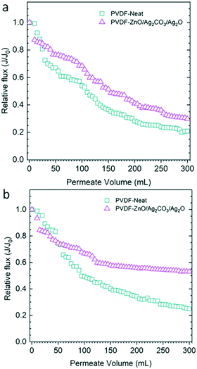 | ||
| Fig. 8 Flux decline during filtration of IBU solutions under (a) dark and (b) under visible light irradiation. Adapted from ref. 7. Copyright 2019©Elsevier. | ||
Photocatalytic degradation of tetracycline
Tetracycline (TC) is a broad-spectrum antibiotic used for the treatment of bacterial infections in animals and humans.5 Cui et al. prepared a Ti/BiOI-polydopamine/cellulose acetate (Ti/BiOI-pDA/CA) photocatalytic membrane for the degradation of TC in wastewater using visible light irradiation.5The pDA/CA membrane structure was synthesized using self-polymerization of dopamine hydrochloride at room temperature, while the Ti-doped BiOI photocatalyst was synthesized by a one-pot solvothermal process, after which pDA/CA was added to obtain a homogeneous mixture.5 The optical absorption properties of the fabricated photocatalytic membrane were measured using UV-vis absorption/diffusion reflectance spectra (DRS) and as expected the Ti/BiOI-pDA/CA membrane showed maximum absorption intensity in the UV-vis region.5 Cui et al. determined that Ti/BiOI had superior adsorption ability towards TC, which was beneficial for the photodecomposition of the pollutant. The photocatalytic activity of the membrane was further tested for TC removal efficiency by assessing the TC concentration in the feed and permeate. They found that 98% removal of tetracycline was achieved using the Ti/BiOI-pDA/CA membrane under visible light irradiation.5 The high removal efficiency was attributed to the introduction of pDA to the membrane, because it reinforced light absorption and effectively promoted the separation and transfer of charge carriers.5
Additionally, the recyclability and stability of the fabricated membrane were studied over repeated photocatalytic removal of tetracycline, with the membrane being washed three times between cycles.5 The removal efficiency of the membrane was almost unchanged after six cycles, and this indicated that the membrane was stable and had reuse potential.5
Photocatalysis of chloramphenicol wastewater
Chloramphenicol (CAP) is another antibiotic frequently used by humans and other mammals; however, the drug has adverse effects with excessive use and has been detected in surface water. Singh et al. fabricated a TiO2-hydroxyapatite (HAP) membrane for the treatment of CAP under UV irradiation.56The TiO2-HAP photocatalyst was blended in polysulfone (PSf) membranes and the performance was evaluated against a pristine PSf membrane using liquid chromatography-mass spectrometry (LC-MS) to measure CAP levels in the feed and permeate. It was determined that blending the TiO2-HAP photocatalyst in the membrane resulted in improved hydrophilicity of the PSf membrane, which resulted in increased flux rate of 4.5 L min−1. Further, the maximum CAP removal observed was 61.59%, and was attributed to oxidizing superoxide radicals and holes of the fabricated membrane.56
PMRs for antibiotic resistance
Given the widespread use of antibiotics, the emergence of antibiotic resistant bacteria (ARB) in wastewater poses a challenge because they are not effectively removed with biological treatment. Most WRRFs are not designed to remove ARB, but instead, they become a major source of ARB proliferation from the high concentration of activated sludge used in biological treatment.57While UV treatment can damage the ARB cell resulting in inactivation, employing high-intensity UV continuously to treat wastewater has significant challenges. Ren et al. functionalized the surface of an UF PVDF membrane with a TiO2 photocatalyst as a treatment technology for ARB and assessed its photocatalytic and antifouling properties against a pristine membrane.48
The performance of the membrane was evaluated for the removal of tetracycline resistant bacteria (TRB), chloramphenicol resistant bacteria (CRB) and sulfadiazine resistant bacteria (SRB). It was determined, as seen in Fig. 9a, that the modified membrane achieved significant retention of ARB even without UV irradiation, and this was attributed to the reduced pore size – 17 nm for the pristine PVDF and 6 nm for the TiO2-PVDF membrane.48Fig. 9a further shows that when photocatalysis is used, over 99.9% of bacteria were removed.48
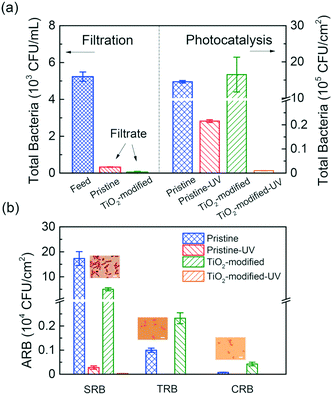 | ||
| Fig. 9 a) (Left) Total bacterial count in the feed and filtrate from UF. (Right) Photocatalytic degradation of bacteria after irradiation with UV for different membranes. (b) Colony-forming units for each ARB before and after the photocatalytic reaction for pristine and TiO2 modified membranes. Adapted from ref. 48. Copyright 2018©American Chemical Society. | ||
Fig. 9b shows the removal of each type of ARB. It can be seen that the membrane had better efficiency for TRB and CRB than SRB. The authors determined that the rod-shaped SRB bacillus had a larger size than the spherical-shaped TRB and CRB cocci, which slightly reduced the efficiency.48
Confocal laser scanning microscopy (CLSM) analysis was further used to demonstrate the effect TiO2 photocatalysis on ARB inactivation and is shown in Fig. 10. The population density of intact and dead bacteria was assessed, and it was determined that membrane surface functionalization with TiO2 was a crucial step to achieve high bacterial inactivation.48
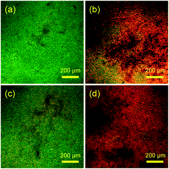 | ||
| Fig. 10 Confocal laser scanning microscopy images of intact bacteria (green) and damaged bacteria (red) on (a) pristine PVDF membrane, (b) pristine PVDF membrane with UV irradiation, (c) TiO2-PVDF membrane and (d) TiO2-PVDF membrane after UV irradiation. Adapted from ref. 48. Copyright 2018©American Chemical Society. | ||
PMRs and fouling
Antifouling properties of PMRs
Fouling has been a critical challenge in membrane processes and causes reduced water flux and reduced separation efficacy, which further increases the operational cost due to the reduced membrane lifetime span.58Geng et al. developed a TiO2/PES-F-COOH membrane, where PES stands for polyethersulfone, and evaluated its antifouling, self-cleaning, and separation properties using a polyacrylamide (PAM) foulant solution.58 The hybrid TiO2/PES-F-COOH ultrafiltration membranes were fabricated using a non-solvent induced phase inversion and assessed for hydrophilicity. The hydrophilic properties of the membrane were investigated by measuring the contact angle. As shown in Fig. 11a, the contact angle decreased with increasing photocatalyst concentration. The reduced contact angle indicated increased surface hydrophilicity, which further increased the water flux, as seen in Fig. 11b.58 The authors also determined that increases in the photocatalyst concentration led to increased pore size, and this accounted for the slightly decreasing retention rate in Fig. 11b.58
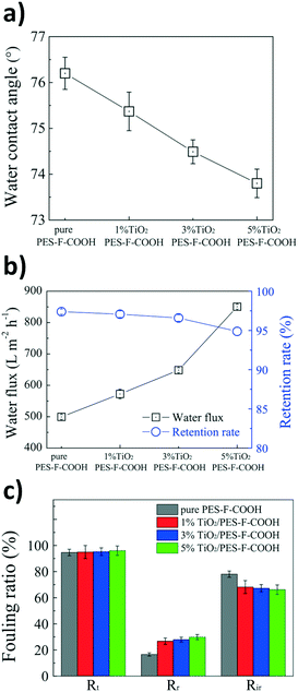 | ||
| Fig. 11 a) Water contact angle for the PES-F-COOH membranes with increasing TiO2 percentage, b) water flux and retention rate for the PES-F-COOH membranes with increasing TiO2 percentage, and c) fouling ratios: total (Rt), reversible (Rr), and irreversible (Ri) for the PES-F-COOH membranes with increasing TiO2 percentage. Adapted from ref. 58. Copyright 2017©Elsevier. | ||
However, an increase in the reversible fouling ratio (Rr) and a decrease in the irreversible fouling ratio (Rir), as seen in Fig. 11c, were observed as a result of increasing the photocatalyst concentration on the membrane. These results indicated that the antifouling properties of the membrane were improved by the incorporation of the TiO2 photocatalyst.58
Photocatalysis and biofouling
In membrane-based water treatment, biofouling is a critical obstacle that causes a significant decrease in water flux and increased energy consumption.59 The biofouling is caused by microbial growth on the surface of the membrane, which forms a biofilm. Fouled membranes are conventionally cleaned in regular intervals of chemical treatment or backwash; however, these cleaning methods can damage the membrane and reduce its lifespan.59Jeong et al. assessed the anti-biofouling properties of a conjugated polyelectrolyte (CPE) grated membrane. Commercial PVDF membranes were modified with a CPE layer to produce PM-Br and further modified with NaOH to produce PM-OH. Escherichia coli and Staphylococcus aureus were used to assess the antimicrobial properties of PM-OH under visible light, while the photocatalytic activity of the membrane was assessed by the degradation of MB, RhB and hexavalent chromium.
Fig. 12a shows the PM-OH membrane's three hour performance in destroying the organic dyes MB (90% efficiency) and RhB (85% efficiency) by recording the initial absorbance of the solution and after 3 hours. Fig. 12b shows 95% efficiency for reducing toxic hexavalent chromium at pH 3 after 3 hours. Additionally, Fig. 12c indicates the anti-biofouling properties of the membrane as it achieved >99% inactivation of microbes forming the biofilm.
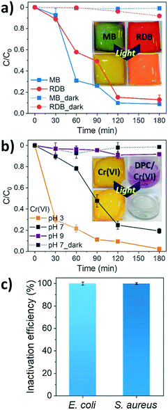 | ||
| Fig. 12 Performance of PM-OH in the a) photocatalytic degradation of MB and RhB, b) photocatalytic reduction of Cr6+ under visible light exposure for 3 hours, and c) inactivation of E. coli and S. aureus on PM-OH. Adapted from ref. 59. Copyright 2021©Elsevier. | ||
Improvement of photocatalytic and antifouling properties by nanoparticle incorporation
Some photocatalysts, such as TiO2, have high recombination rates in which the electron and hole are returned to their original state – this creates a significant limitation to the use of these photocatalysts.60 To overcome this limitation, the photocatalyst can be decorated, in which it is doped with a plasmonic particle, such as silver (Ag) or gold (Au), which captures the electron carrier from the initial nanoparticle – thus enhancing the photocatalytic efficiency.60 Anvari et al. polymerized hydrophilic cellulose acetate (CA) discs with polyacrylic acid (PAA) and created a PMR with TiO2@Fe3O4 decorated with Ag–Au for enhanced photocatalysis.60Surface modification of the membrane improved the flux recovery ratio (RRF) through three fouling cycles.60 The PAA-CA and photocatalyst attachment improved the antifouling properties of the membrane.60 Additionally, Anvari et al. determined from Fig. 13a that the unmodified membrane had the highest flux decline, and this decline was reduced with surface modification of the membrane.
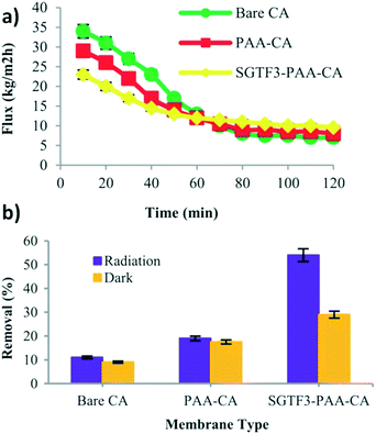 | ||
| Fig. 13 a) Flux performance of bare, PAA-CA and SGTF3-PAA-CA membranes during textile wastewater filtration, and b) MO degradation before and after irradiation. Adapted from ref. 60. Copyright 2021©Wiley. | ||
It was further determined that the fabricated membrane, SGTF3-PAA-CA, achieved 54% methyl orange removal under irradiation, compared to the bare CA membrane (11%) and PAA-CA membrane (19%), as shown in Fig. 13b.60 The increase in removal efficiency was attributed to the antifouling properties of the nanoparticles as a result of photocatalysis on the membrane surface.60
Antifouling and self-cleaning properties of PMRs
The compound Cu2ZnSnS4 (CZTS) is a p-type semiconductor with a band gap equal to 1.5 eV, so in the visible range, it is composed of non-toxic and earth-abundant elements.61 Due to its capacity to absorb radiation in the visible spectrum, it has been used in thin-film solar cells.62,63 However, recently, CZTS has expanded its potential applications as a photocatalyst for PMRs.Ocakoglu et al. investigated the performance of a CZTS photocatalytic membrane for the treatment of basic red 18 dye as a model dye and bovine serum albumin (BSA) as a model protein.64 The antifouling and self-cleaning properties of the fabricated membrane were also evaluated. Polyethersulfone (PES) was used as the membrane support for the fabrication of the CZTS nanoparticle blended PES membrane which was prepared using the inversion method. The ratio of CZTS in the membrane varied from 0.25 wt% to 2.00 wt%. It was determined that the steady-state dye fluxes were higher than the bare PES membrane flux, as shown in Fig. 14A; however, the dye flux decreased with increasing ratio of CZTS nanoparticles.
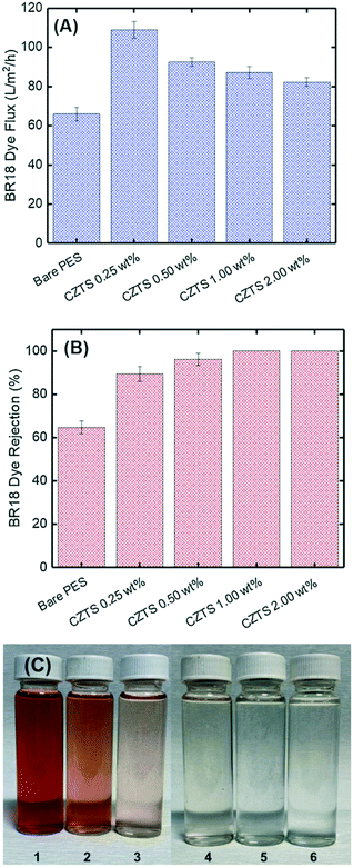 | ||
| Fig. 14 Treatment of basic red 18 (BR18) dye solution. (A) Flux, (B) rejection, and (C) picture of the permeate: 1. feed BR18, 2. bare membrane permeate, 3–6. CZTS0.25–CZTS2.00 wt%. Adapted from ref. 64. Copyright 2021©Elsevier. | ||
Further, the CZTS blended into the membrane improved the dye rejection efficiency from 89.5% to 100% with increasing CZTS ratio from 0.25 wt% to 2.00 wt%, as shown in Fig. 14B. This result was attributed to the increase in the reactive adsorption site availability on the membrane surface.64Fig. 14C corresponds to the improved rejection, as it can be seen that the permeate gradually got clearer and clearer with increasing CZTS ratio.
The authors also assessed the pure water flux of the membrane, which showed an increased flux with increasing CZTS ratio, as seen in Fig. 15A.64 This was attributed to increased hydrophilicity due to surface modification as the contact angle decreased with rising CZTS ratio.64 However, the decrease in the pure water flux for CZTS 2.00 wt% was due to a cluster of photocatalyst nanoparticles in the structure, which also clogged the pores.64
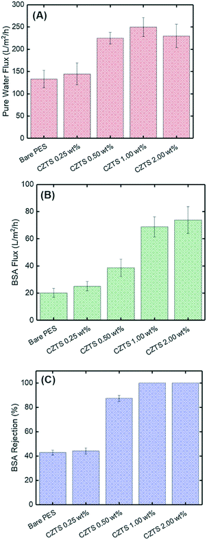 | ||
| Fig. 15 Performance of the CZTS membrane for BSA treatment; (A) pure water flux, (B) BSA solution flux and (C) BSA solution rejection. Adapted from ref. 64. Copyright 2021©Elsevier. | ||
Furthermore, a similar overall trend was seen for the BSA flux increase with increasing CZTS ratio, as seen in Fig. 15B. The performance of the fabricated membrane was also evaluated for protein removal. Similar to the dye rejection, the PMR rejected 100% of the model protein, BSA, as shown in Fig. 15C.64 This increase in BSA rejection was attributed to increased hydrophilicity and decreased pore size with increasing ratio of CZTS.64
Photocatalytic membrane reactors applied to real matrices for wastewater treatments
The wastewater from real matrices, such as urban, rural, industrial, and water body surface (i.e., seas, rivers, lakes) waters, imposes many challenges related to the inherent complexity of the matrix, which can account for many interferents.Anticancer drugs represent a risk to wastewater because they are not completely metabolized by the human body and have low biodegradability and high urine excretion ratio.65,66 To study the PMR performance on secondary treatment for the elimination of anticancer drugs from real wastewater, Janssens et al. spiked the drugs 5-fluorouracil, cyclophosphamide, and capecitabine into a secondary wastewater effluent collected from the municipal wastewater treatment plant in Louvain-la-Neuve, Belgium.67 The molecular structure of each drug is shown in Fig. 16a–c. Each drug was spiked with an individual initial concentration of 500 μg L−1. As a comparison, the three drugs with the same concentration were spiked in lab-grade deionized water.
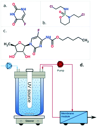 | ||
| Fig. 16 Molecular structures of a) 5-fluorouacil, b) cyclophosphamide, and c) capecitabine; d) scheme of the PMR, showing the reactor and membrane module compartments. Adapted from ref. 67. Copyright 2021©American Chemical Society. | ||
The secondary wastewater effluent underwent filtration pretreatments by nanofiltration and reverse osmosis to identify which species could impact the photocatalytic activity. Then, the effluent was transferred to the reactor, containing UV light (low-pressure Hg lamp with monochromatic emission centered at 254 nm) and suspended TiO2 P25 nanoparticles. Following that, the effluent is transported to the membrane module by a double diaphragm pump. The membrane active layer was made of ZrO2, with an active surface area of 4.7 × 10⁻³ m2, attached to an Al2O3 tubular support. A scheme of the reactor is shown in Fig. 16d. Finally, the concentrations of the drugs in the permeate were analyzed by ultra-performance liquid chromatography tandem mass spectrometry (UPLC-MS).
The photocatalytic process followed a pseudo-first-order kinetics. For the experiments carried out in lab-grade deionized water, 5-fluorouracil, cyclophosphamide, and capecitabine presented photocatalytic degradation rate constants around 0.08, 0.09, and 0.14 min−1, respectively. Meanwhile, for the experiments using the secondary effluent as the matrix, the rate constants for all the drugs were lower than 0.03 min−1, as shown in Fig. 17.
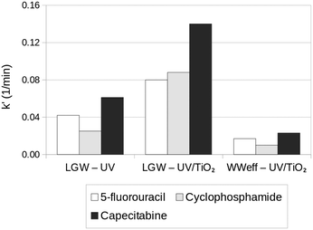 | ||
| Fig. 17 Pseudo-first-order apparent rate constants (k′) obtained by UV (photolysis) and UV/TiO2 (photocatalysis, TiO2 dosage = 1.5 g L−1) of the three anticancer drugs spiked in laboratory grade water (LGW) and secondary wastewater effluent (WWeff) at 500 μg L−1. Adapted from ref. 67. Copyright 2021©American Chemical Society. | ||
This decrease in the photocatalytic activity of the samples in the secondary effluent matrix was attributed to the presence of natural organic matter in the secondary effluent, which could decrease the photocatalytic activity by competing with the photocatalyst for UV light absorption. The natural organic matter could also have scavenged oxidative radicals. A second possible effect could be based on the explanation that even without natural organic matter, there are ions like SO42−, NO3−, Cl−, HCO3−, and Ca2+ that can hinder OH˙ production through photocatalyst active site deactivation by adsorption, photocatalyst aggregation, and radical scavenging. To overcome these issues, the authors suggested using TiO2 with anisotropic morphologies, for instance, TiO2 nanotube arrays, in future works.67
Veterinary medicines are another concerning water pollutant category, as they usually undergo little metabolization in animal organisms; they are excreted without molecular structure changes.68,69 In this sense, Espindola and co-workers studied the removal of the veterinary antibiotic oxytetracycline by TiO2 P25 photocatalysts by spiking oxytetracycline into a secondary effluent from an urban wastewater treatment in northern Portugal.70 As a comparison, experiments were carried out also by spiking oxytetracycline in ultra-pure deionized water. The initial oxytetracycline concentration in the feed was 5 mg L−1.
The main subject of this paper was to study the effect of the TiO2 distribution throughout the reactor. In this sense, the PMR was assembled with suspended or immobilized TiO2 nanoparticles. The radiation source used in these experiments was made up of two UV-A lamps, with emission centered at 365 nm. In both cases, the non-photoactive microfiltration membrane was made of Al2O3.
For the setup with suspended TiO2, the permeate flux through the membrane was reduced for the experiments using the secondary wastewater effluent compared to the experiments using deionized water. This decrease became more pronounced as the TiO2 dosage increased from 0.1 to 0.4 g L−1.
The TiO2 dosage also influenced the oxytetracycline removal percentage. As the dosage increased from 0.1 to 0.4 g L−1, the time necessary to remove 90% of oxytetracycline in the initial feed concentration decreased from 180 to 60 minutes.
About the PMR with immobilized TiO2, it presented a worse photocatalytic activity compared to the suspended PMRs. It was able to degrade 85% of oxytetracycline in 300 minutes. This decrease in the photocatalytic activity of the immobilized TiO2 PMR can be attributed to the concealment of the catalyst in the immobilized membrane, making it less accessible to engage in photocatalysis.
However, immobilized TiO2 PMRs presented a lower reduction in the permeate flux than the suspended TiO2 PMRs. Other advantages of the immobilized TiO2 PMR were the possibility of reusing the membrane by cleaning up the photocatalyst after each use and obtaining a higher quality permeate water, presenting dissolved organic carbon levels lower than the ones in the initial feed and in the permeate obtained by the suspended TiO2 PMRs. This lower dissolved organic carbon in the permeate could be attributed to a decrease in the membrane pore size after immobilization. Giwa et al. summarized the main differences between suspended and immobilized photocatalyst PMRs as shown in Fig. 18.71
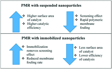 | ||
| Fig. 18 Evaluation of the advantages and disadvantages of suspended and immobilized PMRs. Adapted from ref. 71. Copyright 2021©Elsevier. | ||
A few decades ago, the study of microorganisms in water was very focused on bacteria and viruses. Because they are considered the more pathogenic types of microorganisms, they are generally linked to the causes of gastrointestinal infections and other acute symptoms.72 However, in the last few decades, fungi have emerged as part of the microorganisms category that has been recognized for causing allergies, intoxications, and infections.73 The variety of fungi species is not completely known from the biological perspective. Consequently, the effects of fungi on the surface, ground, and spring water on human health are not completely known either.74 In this sense, it is necessary to have efficient methods to mitigate fungi concentration in real water matrices.
One example of PMR application to mitigate fungi concentration in a real water matrix was carried out by Oliveira and coworkers.75 They prepared membranes of TiO2 P25 deposited onto Al2O3 to study the removal of the filamentous fungus Aspergillus fumigatus spiked in the surface water collected from the Tagus river in Portugal. The water was filtered, and the fungi were spiked with a concentration of 1 × 10⁸ fungi spores per mL in the initial feed. The experiments were conducted by combining two levels of three parameters. One parameter studied was the membrane; a bare Al2O3 membrane and Al2O3 modified with TiO2 P25 were used. The other parameter studied was the matrix, which was the filtered surface water from Tagus river and a saline solution. The third parameter was if the membrane filtering process happened by itself or if it was followed by treatment with UV light with the emission centered at 254 nm.
The results revealed that for both matrices, saline solution and filtered Tagus river water, there was no difference in the fungi rejection and inactivation using the filtration or the filtration coupled with UV treatment. Since in all these cases, it was possible to reject and inactivate 100% of the spores present in the initial feed, both for the unmodified membrane and the membrane modified with TiO2. Meanwhile the fungi spore adsorption was slightly better in the unmodified membrane (73%) than in the TiO2 modified membrane (66%). The difference in adsorption performance was explained by the fact that the unmodified membrane had pores with an average size in the same order of magnitude as the fungi spore's size. In contrast, the TiO2 modified membrane had an average pore size about three orders of magnitude smaller than the average spore size. This difference in pore sizes allows the spores to penetrate and get trapped inside the unmodified membrane, whereas for the TiO2 modified membrane, the spores remained on its surface. This difference in pore sizes also influences the probability of fouling of the membranes. Since in the TiO2 modified membrane the spores are located on the surface, it is easier to clean and maintain this membrane. In contrast, for the unmodified membrane, the location of the spores inside the membrane makes it more prone to fouling.
Considering the diversity of matrices, pollutants, and different types and configurations of the PMRs, it would be impossible to cover every possibility in this review. Thus, for the readers looking for more information about PMR applications to real matrix situations, Table 1 lists different papers according to the type of real matrix, pollutant species, and PMR active photocatalytic material.
| Pollutant | Matrix | Photocatalyst | Radiation | Result | Ref. |
|---|---|---|---|---|---|
| Total organic carbon (TOC) | Secondary wastewater from a city treatment plant | TiO2 – P25 supported on ZrO2 | UV | Removal of 61% of TOC after 5 h | 76 |
| Carbamazepine, diclofenac, and trimethoprim | Secondary wastewater from a city treatment plant | N-Doped TiO2 | Solar | Removal of 27% carbamazepine, 100% diclofenac, and 55% trimethoprim after 5 h | 77 |
| Amoxicillin | Secondary wastewater from a city treatment plant | TiO2 – P25 supported on ceramic membranes | UV-C | Removal of 44% amoxicillin | 78 |
| Imipenem and meropenem (antibiotics) | River water | TiO2 – P25 | Solar | Removal of 80% imipenem and 70% meropenem after 45 and 30 min, respectively | 79 |
| Carbamazepine | Lake water | N-Doped TiO2 supported on Al2O3 membranes | Solar | Rate constant was 44% smaller than the rate constant for the process in deionized water | 80 |
| Bacteriophage MS2 virus | Lake water | N-Doped TiO2 supported on Al2O3 membranes | Solar | MS2 adsorption 65% higher than the value for the process in deionized water | 81 |
| Natural organic matter (NOM) | Natural surface water | TiO2 – P25 | UV-C | Removal of about 80% of NOM after 48 h | 82 |
| Diclofenac, ibuprofen, naproxen | Primary and secondary wastewater from a city treatment plant | TiO2 – P25 | UV-C | For primary wastewater, the diclofenac, ibuprofen, and naproxen removal values were 100%, 73%, and 90%. For secondary wastewater, the removal values were 100%, 93%, 94% | 83 |
| Diclofenac | Surface water from a city water treatment plant | TiO2 – P25 | UV-C | The diclofenac removal varied about 56 and 100%, depending on the experimental condition | 84 |
Future outlook and perspectives
Although the PMR has been established as a viable technology for wastewater treatment, there is still space for innovation and improvement in different fields, such as photocatalysts and reactor designs.Advances in photocatalysts
In the photocatalyst area, since TiO2 is the widely used photocatalyst material, there are other means besides doping to make it able to absorb visible radiation. One possible way to tune the band gap is by controlling the TiO2 morphology. For instance, Rosales and co-workers studied the influence of one-dimensional TiO2 morphologies on the band gap and generation of reactive oxygen species.85 The authors prepared TiO2 nanotubes, nanofibers, nanorods, and nanowires. The transmission electron microscopy images of the different morphologies are shown in Fig. 19.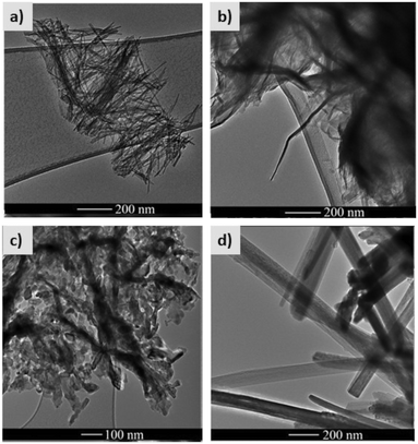 | ||
| Fig. 19 High resolution transmission electron microscopy images of TiO2 a) nanotubes, b) nanofibers, c) nanorods, and d) nanowires. Adapted from ref. 85. Copyright 2019©Elsevier. | ||
TiO2 samples with different morphologies were prepared by a hydrothermal method, by varying the heating temperature and the titanium source. The efficiency of reactive oxygen species production was monitored through three different tests: (1) fluorescence detection of the products of terephthalic acid hydroxylation to detect OH˙ production by the photocatalyst; (2) bleaching of N,N-p-nitrosodimethylaniline at 440 nm by histidine and singlet oxygen produced by the photocatalyst; (3) methyl orange photocatalytic degradation excited by visible light.
Table 2 presents the results for the band gap and each of the three tests to monitor the production of reactive oxygen species for each of the one-dimensional TiO2 morphologies.85
| Sample | Band gap (eV) | OH˙ production ranking | 1O2 production ranking | MO degradation ranking |
|---|---|---|---|---|
| Anatase TiO2 | 3.02 | — | — | — |
| Rutile TiO2 | 2.87 | — | — | — |
| Nanotubes | 3.04 | 2nd | 2nd | 2nd |
| Nanofibers | 2.92 | 1st | 1st | 1st |
| Nanorods | 3.02 | 3rd | 3rd | 3rd |
| Nanowires | 3.25 | 4th | 4th | 4th |
The best performance for the TiO2 nanofibers was explained by a higher number of oxygen vacancies on the surface of this material, which can benefit the production of reactive oxygen species.85
Another way to tune the TiO2 band gap is by preparing a TiO2 variety called black-TiO2. Black-TiO2 has an outstanding ability to absorb energy from the full sunlight emission spectrum, from the UV until the infrared range. White TiO2 can be turned into black-TiO2 by different Ti4+ to Ti3+ reduction methods, for instance, self-doping, surface hydroxyl groups, oxygen vacancies, or Ti–H bonds. These structural modifications can lead to changes in the optical properties, and consequently, to the color.86Fig. 20 shows the XRD pattern with the pictures of TiO2−x anatase synthesized by Ti3+ self-doping according to the calcination temperature and the respective color of the powders.87
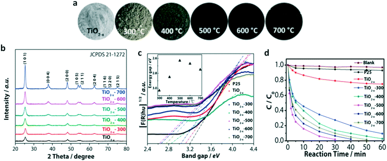 | ||
| Fig. 20 a) Pictures of the black-TiO2 powders prepared with post-annealing treatment in the range of 300–700 °C, b) XRD patterns of the black-TiO2 powders prepared with post-annealing treatment in the range of 300–700 °C, c) band gap energy of the black-TiO2 powders prepared with post-annealing treatment in the range of 300–700 °C, d) methylene blue photocatalytic degradation data for the black-TiO2 powders prepared with post-annealing treatment in the range of 300–700 °C. Adapted from ref. 87. Copyright 2015©Elsevier. | ||
Metal-free photocatalysts have inherently low toxicity. So, advances in photocatalyst production should consider this category of material. An emerging metal-free photocatalyst is graphitic carbon nitride (g-C3N4).88 g-C3N4 is a layered material, where the individual layers stack together similar to the way graphene sheets stack in graphite. The g-C3N4 band gap is around 2.7 eV, so it can be excited by visible light until 470 nm. Additionally, it is non-toxic, resistant to chemical attack, and thermally stable up to 600 °C.88 Xu and co-workers used g-C3N4 for methylene blue photocatalytic degradation. They were able to eliminate about 97% of the initial methylene blue concentration after 120 minutes.89 The irradiation source, in this case, was a simulated sunlight system. The photocatalyst also showed exceptional recycling performance since it could be used for five cycles without harming its activity.89
Advances in reactors
PMRs have indicated great potential for wastewater treatment. However, their large-scale application is limited by different drawbacks related to reaction kinetics and reactor configurations.Several studies have demonstrated successful pilot-scale application of different PMRs for wastewater treatment.84,90,91 The inclusion of air bubbles using a porous diffuser in the membrane compartment was described in several pilot-scale studies.84,90 Plakas et al. demonstrated the use of an automated continuous flow PMR unit (with a separate membrane vessel and photoreactor chamber) to successfully remove diclofenac, a recalcitrant micropollutant, from wastewater.84 The system contained suspended TiO2 photocatalysts with UF. A picture of the reactor used by Plakas et al. is shown in Fig. 21.
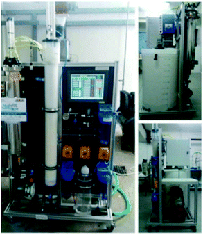 | ||
| Fig. 21 Pilot scale PMR used by Plakas et al., front and side views. Adapted from ref. 84. Copyright 2016©Elsevier. | ||
Another pilot-scale application was carried out by Ryu et al. in a continuous flow PMR unit having a 500 L volume.90 In this study, the removal efficiency of various organic pollutants from feed water was evaluated. TiO2 (a mixture of 80% anatase and 20% rutile), with an average surface area of 50 m2 g−1, was selected as a photocatalyst. A single reactor housed the membranes and the light sources (blacklight blue, BLB, lamps), and a suction pump was used to draw out the permeate water through a 0.1 μm hollow fiber membrane (MF) module.90 While organic contaminants like 4-chlorophenol (at 100 ppb initial concentration) were degraded within 2 h of batch operation, humic acid and dyes (rhodamine B, methylene blue), at ppm levels of initial concentration, took longer reaction times to complete degradation. In continuous operation, no fouling of the membranes (or no suction pressure build-up) took place with the intermittent operation of 9 min suction and 3 min pause periods.90
Most studies reporting bench-scale reactor setups have successfully applied PMRs as an advanced wastewater treatment and recovery technology. It should be kept in mind that these reactors will not be efficient as standalone treatment units for different wastewater streams. Instead, they will be effective as an advanced treatment strategy following a series of primary and secondary treatment processes (depending on the wastewater characteristics). With appropriate pretreatment of feed water (to achieve acceptable levels of turbidity and contaminant load), the PMRs will efficiently transmit UV/visible light throughout the reactor and operate longer without significant fouling on the membranes. However, further pilot-scale studies are required with various wastewater streams to establish operational criteria for PMRs with varying configurations. The different PMR configurations have niche application possibilities depending on the availability of space and resources.
Both UV and sunlight sources have been used in different studies with appropriate photocatalysts. The most common configurations involve irradiation of the sample using (a) a light source located outside the reactor (used with both UV and sunlight sources) or (b) immersing a UV lamp in the axial position in the reactor. Fig. 22 shows a scheme of the reactor with an external light source and with the light source immersed inside the reactor.46
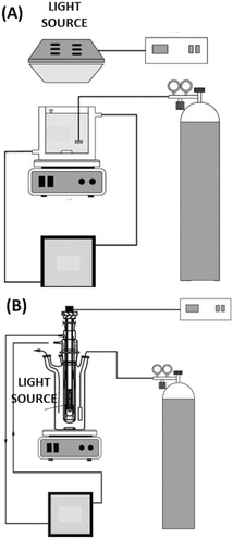 | ||
| Fig. 22 PMR with (A) external light source and (B) light source immersed in the reactor. Adapted from ref. 46. Copyright 2004©Elsevier. | ||
The light source type is another prolific field to be explored towards PMR improvement. Usually, the UV light sources are mercury lamps, either lower or higher pressure. Meanwhile the visible light lamps are made of tungsten. Both light sources consume a considerable amount of energy. To overcome this energy consumption issue, the modern PMRs should try to rely on light emitting diode (LED) light sources. LEDs have the advantage of emitting in a narrower wavelength range than conventional lamps, decreasing the use of filters.92 Additionally, LEDs are lighter, smaller, and operate at lower temperatures, which decreases the amount of energy that is dissipated as heat, consequently reducing energy consumption.93 Wang et al. described the use of PMRs with a submerged visible light LED array.94 This PMR used TiO2 as a photocatalyst and operated in the microfiltration regime. A scheme of the PMR is shown in Fig. 23. The authors studied the effect of the light intensity on the elimination of the pharmaceutical molecule carbamazepine from a simulated water as the feed. The authors concluded that a higher light intensity emitted by the LED array led to an increase in the rate constant of the carbamazepine degradation process.94
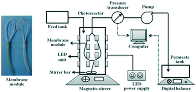 | ||
| Fig. 23 Scheme of the PMR using a submerged visible LED array, with a picture of the actual membrane module on the left side. Adapted from ref. 94. Copyright 2013©Elsevier. | ||
The combination between aeration and a submerged oscillatory membrane was recently used to remove a mixture of four micropollutant pharmaceutical molecules: antipyrine, sulfamethoxazole, diclofenac sodium salt, and hydrochlorothiazide, all dissolved in MilliQ water.95 The photocatalyst was TiO2 illuminated by UV-light. The scheme of the submerged oscillatory PMR is shown in Fig. 24.
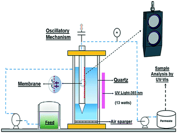 | ||
| Fig. 24 Scheme of the oscillatory submerged PMR used to degrade pharmaceutical molecules. Adapted from ref. 95. Copyright 2021©Elsevier. | ||
The authors used a central composite design (CCD) of experiments to study the effects of the membrane oscillation amplitude, oscillation frequency, and airflow rate on the maximization of the micropollutant removal and minimization of the flux decline.
The central composite design of experiments allowed the authors to obtain an empirical model and use the response surface methodology to conclude that the best combination of factors was membrane oscillation amplitude and frequency equal to 2 mm and 4.67 Hz along with an airflow rate of 0.65 LPM. The highest removal happened for sulfamethoxazole (90%) and the lowest for antipyrine (68%). The removal of all micropollutants was decreased when humic acid was present, due to humic acid adsorption onto TiO2, reducing the amount of its available catalytic sites.95
This study also showed the importance of applying statistical techniques, such as the design of experiments to minimize the number of experiments, statistically support the role of each factor in the process, and work with response surface methodologies to predict the results under conditions initially untested.96 Definitely, many water treatment studies can benefit from this type of statistical approach.
Sophisticated membrane designs combined with membrane flux control are a good way to mitigate membrane fouling. For instance, Yang et al. prepared a system coupling PMRs and dynamic membranes (DM) to mitigate the fouling of the membranes by humic acid in water.97 These dynamic membranes are low-pressure membranes used to prevent the contact of the foulants with the primary membrane. The DM was prepared by filtering a TiO2 suspension through a flat sheet Al2O3 ceramic membrane. The PMR/DM was designed to operate in the sub-critical flux regime, which is below the flux where fouling is no longer negligible. The synergistic effect of the PMR and DM led to fouling mitigation. This mitigation was possible because the hydrophobic humic acid molecules were photocatalytically degraded with the assistance of UV light onto the TiO2-DM surface. The products of this degradation were mostly hydrophilic medium molecular weight products. Only the products with smaller molecular weight could pass through the DM pores and reach the primary membrane. Meanwhile, the products unable to pass through the DM were detached from the TiO2-DM surface by shear forces. Because only smaller molecules could reach the primary membrane, the fouling ended up being mitigated.97
Another way to promote the antifouling properties in the PMRs can be done by taking advantage of the different coverages of the TiO2 photocatalytic membrane combined with varying the type of flow between dead-end and cross-flow modules.98 For example, Ahmad et al. controlled the TiO2 coverage onto the Al2O3 ceramic membranes.98 The difference in coverage was attained by using different polymeric templates during titanium(IV) isopropoxide (TTIP) deposition onto Al2O3 to produce a TiO2 layer. For producing a fully covered TiO2 layer, the authors used poly(ethylene glycol)-block-poly(propylene glycol)-block-poly(ethylene glycol) (P123) as the polymeric template. Meanwhile for producing the partially covered TiO2 layer, they used poly(vinyl pyrrolidone) (PVP). Contact angle measurements revealed that the partially covered membrane is more hydrophilic than the uniformly covered one. A summary of the different preparation processes is shown in Fig. 25.
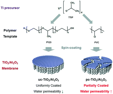 | ||
| Fig. 25 Scheme of the preparation of the uniformly (left) and partially coated (right) TiO2 membranes deposited onto porous Al2O3. Adapted from ref. 98. Copyright 2020©Elsevier. | ||
The fouling behavior of the membranes was studied using a congo red solution as the feed. It started with a dead-end flow with the UV light off. During the first two hours of the experiment there was a decrease in the permeate flux for both types of membranes. The second stage was carried out in the cross-flow mode with the UV light on, leading to the recovery of permeate flux. Finally, the third stage was again carried out in dead-end mode with UV light off, and there was a decrease in the permeate flux for both membranes. However, the decrease was much milder for both membranes than for the bare Al2O3 ceramic membrane, showing that the TiO2, either uniform or partial, decreases the fouling of the membranes.98
Conclusions
Surface modification of membranes has been proven to improve membrane hydrophilicity and pore size, thus improving membrane performance. The antifouling properties of photocatalytic membranes allow for their reuse without significant impact on performance. Photocatalytic membrane reactors are a developing technology for wastewater treatment with promising results from the studies reviewed. The technology has been developed to achieve quantitative removal of microbes and dyes from wastewater; however, significant development is needed for the efficient removal of more complex organic structures, such as pharmaceuticals like chloramphenicol and ibuprofen. Further, the use of visible light irradiation has shown lower removal efficiency compared to studies using UV light irradiation. Additionally, more development is needed for membrane fabrication technologies because coating can lead to the leaching of the photocatalyst and blending/incorporating the catalyst in the membrane structure can cause pore clogging, which has an adverse impact on the flux rate. Photocatalysis has been proven to be effective for less complex feed types; however, due to the myriad of contaminant types in municipal and industrial wastewater, for this technology to be employed widely there needs to be a robust photocatalytic membrane that performs efficiently under visible light radiation to reduce the energy requirement.Author contributions
Andrew Ashley – data curation, writing original draft. Brandon Thrope – data curation, writing original draft. Mahbubhoor R. Choudhury – conceptualization, data curation, writing – original draft, writing – review & editing. Alexandre H. Pinto – conceptualization, data curation, writing – original draft, writing – review & editing, supervision, project administration.Conflicts of interest
There are no conflicts to declare.Acknowledgements
The authors would like to thank the Manhattan College Office of the Provost Summer 2020 Grant and Manhattan College School of Science Summer 2020 Research Scholarship.Notes and references
- National Academies of Sciences Engineering and Medicine, Environmental Engineering for the 21st Century, National Academies Press, Washington, D.C., 2019, Available from: https://www.nap.edu/catalog/25121 Search PubMed.
- Inamuddin, M. I. Ahamed and E. Lichtfouse, in Water Pollution and Remediation: Heavy Metals, ed. Inamuddin, M. I. Ahamed and E. Lichtfouse, Springer International Publishing, Cham, 2021 Search PubMed; Environmental Chemistry for a Sustainable World, vol. 53, Available from: http://link.springer.com/10.1007/978-3-030-52421-0 Search PubMed.
- W. S. Koe, J. W. Lee, W. C. Chong, Y. L. Pang and L. C. Sim, An overview of photocatalytic degradation: photocatalysts, mechanisms, and development of photocatalytic membrane, Environ. Sci. Pollut. Res., 2020, 27(3), 2522–2565 CrossRef CAS.
- H. Zhang, X. Quan, S. Chen, H. Zhao and Y. Zhao, Fabrication of photocatalytic membrane and evaluation its efficiency in removal of organic pollutants from water, Sep. Purif. Technol., 2006, 50(2), 147–155 CrossRef CAS.
- Y. Cui, L. Yang, Y. Yan, Z. Wang, J. Zheng and B. Li, et al., Nature-mimicking fabrication of antifouling photocatalytic membrane based on Ti/BiOI and polydopamine for synergistically enhanced photocatalytic degradation of tetracycline, Korean J. Chem. Eng., 2021, 38(2), 442–453 CrossRef CAS.
- C. Comninellis, A. Kapalka, S. Malato, S. A. Parsons, I. Poulios and D. Mantzavinos, Advanced oxidation processes for water treatment: advances and trends for R&D, J. Chem. Technol. Biotechnol., 2008, 83(6), 769–776, DOI:10.1002/jctb.1873.
- N. Rosman, W. Norharyati Wan Salleh, N. Aqilah Mohd Razali, S. Z. Nurain Ahmad, N. Hafiza Ismail, F. Aziz, Z. Harun, A. Fauzi Ismail and N. Yusof, Ibuprofen removal through photocatalytic filtration using antifouling PVDF- ZnO/Ag2CO3/Ag2O nanocomposite membrane, Mater. Today: Proc., 2021, 42(Part 1), 69–74, DOI:10.1016/j.matpr.2020.09.476.
- N. Nasrollahi, L. Ghalamchi, V. Vatanpour and A. Khataee, Photocatalytic-membrane technology: a critical review for membrane fouling mitigation, J. Ind. Eng. Chem., 2021, 93, 101–116, DOI:10.1016/j.jiec.2020.09.031.
- S. N. Ahmed and W. Haider, Heterogeneous photocatalysis and its potential applications in water and wastewater treatment: A review, Nanotechnology, 2018, 29(34), 342001 CrossRef.
- K. Nakata, T. Ochiai, T. Murakami and A. Fujishima, Photoenergy conversion with TiO2 photocatalysis: New materials and recent applications, Electrochim. Acta, 2012, 84, 103–111, DOI:10.1016/j.electacta.2012.03.035.
- Y. Liao, W. Que, Q. Jia, Y. He, J. Zhang and P. Zhong, Controllable synthesis of brookite/anatase/rutile TiO2 nanocomposites and single-crystalline rutile nanorods array, J. Mater. Chem., 2012, 22(16), 7937–7944 RSC.
- M. Landmann, E. Rauls and W. G. Schmidt, The electronic structure and optical response of rutile, anatase and brookite TiO2, J. Phys.: Condens. Matter, 2012, 24(19), 195503 CrossRef CAS PubMed.
- V. Etacheri, C. Di Valentin, J. Schneider, D. Bahnemann and S. C. Pillai, Visible-light activation of TiO2 photocatalysts: Advances in theory and experiments, J. Photochem. Photobiol., C, 2015, 25, 1–29, DOI:10.1016/j.jphotochemrev.2015.08.003.
- Y. Luo, A. Benali, L. Shulenburger, J. T. Krogel, O. Heinonen and P. R. C. Kent, Phase stability of TiO2 polymorphs from diffusion Quantum Monte Carlo, New J. Phys., 2016, 18(11), 113049 CrossRef.
- D. Reyes-Coronado, G. Rodríguez-Gattorno, M. E. Espinosa-Pesqueira, C. Cab, R. De Coss and G. Oskam, Phase-pure TiO2 nanoparticles: Anatase, brookite and rutile, Nanotechnology, 2008, 19(14), 145605 CrossRef CAS.
- B. Zhao, F. Chen, Q. Huang and J. Zhang, Brookite TiO2 nanoflowers, Chem. Commun., 2009, 5115–5117 RSC.
- S. Cassaignon, M. Koelsch and J. P. Jolivet, Selective synthesis of brookite, anatase and rutile nanoparticles: Thermolysis of TiCl4 in aqueous nitric acid, J. Mater. Sci., 2007, 42(16), 6689–6695 CrossRef CAS.
- J. Zhang, P. Zhou, J. Liu and J. Yu, New understanding of the difference of photocatalytic activity among anatase, rutile and brookite TiO2, Phys. Chem. Chem. Phys., 2014, 16(38), 20382–20386, 10.1039/C4CP02201G.
- M. Qamar, M. Saquib and M. Muneer, Photocatalytic degradation of two selected dye derivatives, chromotrope 2B and amido black 10B, in aqueous suspensions of titanium dioxide, Dyes Pigm., 2005, 65(1), 1–9 CrossRef CAS.
- S. Mozia, Photocatalytic membrane reactors (PMRs) in water and wastewater treatment. A review, Sep. Purif. Technol., 2010, 73(2), 71–91, DOI:10.1016/j.seppur.2010.03.021.
- D. M. Tobaldi, R. C. Pullar, M. P. Seabra and J. A. Labrincha, Fully quantitative X-ray characterisation of Evonik Aeroxide TiO2 P25®, Mater. Lett., 2014, 122, 345–347, DOI:10.1016/j.matlet.2014.02.055.
- J. Grzechulska and A. W. Morawski, Photocatalytic labyrinth flow reactor with immobilized P25 TiO2 bed for removal of phenol from water, Appl. Catal., B, 2003, 46(2), 415–419 CrossRef CAS.
- M. Fligge and S. K. Solanki, The solar spectral irradiance since 1700, Geophys. Res. Lett., 2000, 27(14), 2157–2160 CrossRef CAS.
- G. Thuillier, L. Floyd, T. N. Woods, R. Cebula, E. Hilsenrath and M. Hersé, et al., Solar irradiance reference spectra for two solar active levels, Adv. Space Res., 2004, 34(2), 256–261 CrossRef CAS.
- J. N. Apell and K. McNeill, Updated and validated solar irradiance reference spectra for estimating environmental photodegradation rates, Environ. Sci.: Processes Impacts, 2019, 21(3), 427–437 RSC.
- N. Murakami, T. Chiyoya, T. Tsubota and T. Ohno, Switching redox site of photocatalytic reaction on titanium(IV) oxide particles modified with transition-metal ion controlled by irradiation wavelength, Appl. Catal., A, 2008, 348(1), 148–152 CrossRef CAS.
- L. G. Devi and S. G. Kumar, Influence of physicochemical-electronic properties of transition metal ion doped polycrystalline titania on the photocatalytic degradation of Indigo Carmine and 4-nitrophenol under UV/solar light, Appl. Surf. Sci., 2011, 257(7), 2779–2790, DOI:10.1016/j.apsusc.2010.10.062.
- C. Garcidueñas-Piña, I. E. Medina-Ramírez, P. Guzmán, R. Rico-Martínez, J. F. Morales-Domínguez and I. Rubio-Franchini, Evaluation of the Antimicrobial Activity of Nanostructured Materials of Titanium Dioxide Doped with Silver and/or Copper and Their Effects on Arabidopsis thaliana, Int. J. Photoenergy, 2016, 2016, 8060847, DOI:10.1155/2016/8060847.
- A. Zielińska-Jurek, E. Kowalska, J. W. Sobczak, W. Lisowski, B. Ohtani and A. Zaleska, Preparation and characterization of monometallic (Au) and bimetallic (Ag/Au) modified-titania photocatalysts activated by visible light, Appl. Catal., B, 2011, 101(3–4), 504–514 CrossRef.
- M. C. Hidalgo, M. Maicu, J. A. Navío and G. Colón, Photocatalytic properties of surface modified platinised TiO2: Effects of particle size and structural composition, Catal. Today, 2007, 129(1–2 SPEC. ISS), 43–49 CrossRef CAS.
- C. M. Visinescu, R. Sanjines, F. Lévy, V. Marcu and V. I. Pârvulescu, Tantalum doped titania photocatalysts: Preparation by dc reactive sputtering and catalytic behavior, J. Photochem. Photobiol., A, 2005, 174(2), 106–112 CrossRef CAS.
- L. G. Devi and S. G. Kumar, Exploring the critical dependence of adsorption of various dyes on the degradation rate using Ln3+-TiO2 surface under UV/solar light, Appl. Surf. Sci., 2012, 261, 137–146, DOI:10.1016/j.apsusc.2012.07.121.
- L. G. Devi, B. N. Murthy and S. G. Kumar, Photocatalytic activity of V5+, Mo6+ and Th4+ doped polycrystalline TiO2 for the degradation of chlorpyrifos under UV/solar light, J. Mol. Catal. A: Chem., 2009, 308(1–2), 174–181 CrossRef CAS.
- M. Nasirian, Y. P. Lin, C. F. Bustillo-Lecompte and M. Mehrvar, Enhancement of photocatalytic activity of titanium dioxide using non-metal doping methods under visible light: a review, Int. J. Environ. Sci. Technol., 2018, 15(9), 2009–2032 CrossRef CAS.
- S. E. Bilgin, Solvothermal synthesized boron doped TiO2 catalysts: Photocatalytic degradation of endocrine disrupting compounds and pharmaceuticals under visible light irradiation, Appl. Catal., B, 2017, 200, 309–322, DOI:10.1016/j.apcatb.2016.07.016.
- L. Yu, Y. Lin, J. Huang, S. Lin and D. Li, A Visible Light Photocatalyst of Carbonate-Like Species Doped TiO2, J. Am. Ceram. Soc., 2017, 100(1), 333–342 CrossRef CAS.
- X. Zhang, J. Zhou, Y. Gu and D. Fan, Visible-Light Photocatalytic Activity of N-Doped TiO2 Nanotube Arrays on Acephate Degradation, J. Nanomater., 2015, 2015, 527070, DOI:10.1155/2015/527070.
- S. A. Bakar and C. Ribeiro, A comparative run for visible-light-driven photocatalytic activity of anionic and cationic S-doped TiO2 photocatalysts: A case study of possible sulfur doping through chemical protocol, J. Mol. Catal. A: Chem., 2016, 421, 1–15, DOI:10.1016/j.molcata.2016.05.003.
- W. Diao, J. Xu and X. Rao, et al., Facile Synthesis of Fluorine Doped Rutile TiO2 Nanorod Arrays for Photocatalytic Removal of Formaldehyde, Catal. Lett., 2021 DOI:10.1007/s10562-021-03700-x.
- E. M. Samsudin, S. B. A. Hamid, J. C. Juan, W. J. Basirun, A. E. Kandjani and S. K. Bhargava, Effective role of trifluoroacetic acid (TFA) to enhance the photocatalytic activity of F-doped TiO2 prepared by modified sol-gel method, Appl. Surf. Sci., 2016, 365, 57–68, DOI:10.1016/j.apsusc.2016.01.016.
- X. Feng, P. Wang, J. Hou, J. Qian, Y. Ao and C. Wang, Significantly enhanced visible light photocatalytic efficiency of phosphorus doped TiO2 with surface oxygen vacancies for ciprofloxacin degradation: Synergistic effect and intermediates analysis, J. Hazard. Mater., 2018, 351, 196–205 CrossRef CAS.
- Y. Su, S. Chen, X. Quan, H. Zhao and Y. Zhang, A silicon-doped TiO2 nanotube arrays electrode with enhanced photoelectrocatalytic activity, Appl. Surf. Sci., 2008, 255, 2167–2172 CrossRef CAS.
- X. Hong, Z. Wang, W. Cai, F. Lu, J. Zhang and Y. Yang, et al., Visible-light-activated nanoparticle photocatalyst of iodine-doped titanium dioxide, Chem. Mater., 2005, 17(6), 1548–1552 CrossRef CAS.
- P. Argurio, E. Fontananova, R. Molinari and E. Drioli, Photocatalytic membranes in photocatalytic membrane reactors, Processes, 2018, 6(9), 162, DOI:10.3390/pr6090162.
- R. Molinari, C. Lavorato, P. Argurio, K. Szymański, D. Darowna and S. Mozia, Overview of photocatalytic membrane reactors in organic synthesis, energy storage and environmental applications, Catalysts, 2019, 9(3), 1–39 CrossRef.
- R. Molinari, F. Pirillo, M. Falco, V. Loddo and L. Palmisano, Photocatalytic degradation of dyes by using a membrane reactor, Chem. Eng. Process., 2004, 43(9), 1103–1114 CrossRef CAS.
- T. P. Nguyen, Q. B. Tran, Q. V. Ly, L. Thanh Hai, D. T. Le and M. B. Tran, et al. Enhanced visible photocatalytic degradation of diclofen over N-doped TiO2 assisted with H2O2: A kinetic and pathway study, Arabian J. Chem., 2020, 13(11), 8361–8371 CrossRef CAS.
- S. Ren, C. Boo, N. Guo, S. Wang, M. Elimelech and Y. Wang, Photocatalytic Reactive Ultrafiltration Membrane for Removal of Antibiotic Resistant Bacteria and Antibiotic Resistance Genes from Wastewater Effluent, Environ. Sci. Technol., 2018, 52(15), 8666–8673 CrossRef CAS PubMed.
- M. R. Choudhury, N. Anwar, D. Jassby and M. S. Rahaman, Fouling and wetting in the membrane distillation driven wastewater reclamation process – A review, Adv. Colloid Interface Sci., 2019, 269, 370–399 CrossRef CAS PubMed.
- S. Mozia, M. Tomaszewska and A. W. Morawski, Photocatalytic membrane reactor (PMR) coupling photocatalysis and membrane distillation-Effectiveness of removal of three azo dyes from water, Catal. Today, 2007, 129(1–2 SPEC. ISS), 3–8 CrossRef CAS.
- K. Azrague, P. Aimar, F. Benoit-Marquié and M. T. Maurette, A new combination of a membrane and a photocatalytic reactor for the depollution of turbid water, Appl. Catal., B, 2007, 72(3–4), 197–204 CrossRef CAS.
- G. Camera-Roda, F. Parrino, V. Loddo and L. Palmisano, A dialysis photocatalytic reactor for the green production of Vanillin, Catalysts, 2020, 10(3), 1–13 CrossRef.
- W. Lu, C. Duan, C. Liu, Y. Zhang, X. Meng and L. Dai, et al. A self-cleaning and photocatalytic cellulose-fiber- supported “Ag@AgCl@MOF- cloth” membrane for complex wastewater remediation, Carbohydr. Polym., 2020, 247, 116691, DOI:10.1016/j.carbpol.2020.116691.
- N. M. Mahmoodi, J. Abdi, M. Oveisi, A. M. Alinia and M. Vossoughi, Metal-organic framework (MIL-100 (Fe)): Synthesis, detailed photocatalytic dye degradation ability in colored textile wastewater and recycling, Mater. Res. Bull., 2018, 100, 357–366, DOI:10.1016/j.materresbull.2017.12.033.
- A. Golshenas, Z. Sadeghian and S. N. Ashrafizadeh, Performance evaluation of a ceramic-based photocatalytic membrane reactor for treatment of oily wastewater, J. Water Process. Eng., 2020, 36, 101186 CrossRef.
- A. Singh, S. K. Ramachandran, M. B. Gumpu, L. Zsuzsanna, G. Veréb and S. Kertész, et al. Titanium dioxide doped hydroxyapatite incorporated photocatalytic membranes for the degradation of chloramphenicol antibiotic in water, J. Chem. Technol. Biotechnol., 2021, 96(4), 1057–1066 CrossRef CAS.
- J. Wang, L. Chu, L. Wojnárovits and E. Takács, Occurrence and fate of antibiotics, antibiotic resistant genes (ARGs) and antibiotic resistant bacteria (ARB) in municipal wastewater treatment plant: An overview, Sci. Total Environ., 2020, 744, 140997, DOI:10.1016/j.scitotenv.2020.140997.
- Z. Geng, X. Yang, C. Boo, S. Zhu, Y. Lu and W. Fan, et al. Self-cleaning anti-fouling hybrid ultrafiltration membranes via side chain grafting of poly(aryl ether sulfone) and titanium dioxide, J. Membr. Sci., 2017, 529, 1–10, DOI:10.1016/j.memsci.2017.01.043.
- E. Jeong, J. Byun, B. Bayarkhuu and S. W. Hong, Hydrophilic photocatalytic membrane via grafting conjugated polyelectrolyte for visible-light-driven biofouling control, Appl. Catal., B, 2021, 282, 119587, DOI:10.1016/j.apcatb.2020.119587.
- A. Anvari, M. Amoli-Diva and R. Sadighi-Bonabi, Concurrent photocatalytic degradation and filtration with bi-plasmonic TiO2 for wastewater treatment, Micro Nano Lett., 2021, 16(3), 194–202 CrossRef CAS.
- A. H. Pinto, S. W. Shin, E. Isaac, T. R. Knutson, E. S. Aydil and R. L. Penn, Controlling Cu 2 ZnSnS 4 (CZTS) phase in microwave solvothermal synthesis, J. Mater. Chem. A, 2017, 18;5(44), 23179–23189, 10.1039/C7TA06086F.
- A. H. Pinto, S. W. Shin, E. S. Aydil and R. L. Penn, Selective removal of Cu2-:X (S,Se) phases from Cu2ZnSn(S,Se)4 thin films, Green Chem., 2016, 18(21), 5814–5821 RSC.
- A. H. Pinto, S. W. Shin, A. Sharma, R. L. Penn and E. S. Aydil, Synthesis of Cu2(Zn1-xCox)SnS4 nanocrystals and formation of polycrystalline thin films from their aqueous dispersions, J. Mater. Chem. A, 2018, 6(3), 999–1008 RSC.
- K. Ocakoglu, N. Dizge, S. G. Colak, Y. Ozay, Z. Bilici and M. S. Yalcin, et al. Polyethersulfone membranes modified with CZTS nanoparticles for protein and dye separation: Improvement of antifouling and self-cleaning performance, Colloids Surf., A, 2021, 616, 126230, DOI:10.1016/j.colsurfa.2021.126230.
- K. Kümmerer, A. Al-Ahmad, B. Bertram and M. Wießler, Biodegradability of antineoplastic compounds in screening tests: Influence of glucosidation and of stereochemistry, Chemosphere, 2000, 40(7), 767–773 CrossRef.
- J. P. Besse, J. F. Latour and J. Garric, Anticancer drugs in surface waters. What can we say about the occurrence and environmental significance of cytotoxic, cytostatic and endocrine therapy drugs?, Environ. Int., 2012, 39(1), 73–86, DOI:10.1016/j.envint.2011.10.002.
- R. Janssens, R. Hainaut, J. Gillard, H. Dailly and P. Luis, Performance of a Slurry Photocatalytic Membrane Reactor for the Treatment of Real Secondary Wastewater Effluent Polluted by Anticancer Drugs, Ind. Eng. Chem. Res., 2021, 60(5), 2223–2231 CrossRef CAS.
- A. K. Sarmah, M. T. Meyer and A. B. A. Boxall, A global perspective on the use, sales, exposure pathways, occurrence, fate and effects of veterinary antibiotics (VAs) in the environment, Chemosphere, 2006, 65(5), 725–759 CrossRef CAS PubMed.
- N. Kemper, Veterinary antibiotics in the aquatic and terrestrial environment, Ecol. Indic., 2008, 8(1), 1–13 CrossRef CAS.
- J. C. Espíndola, R. O. Cristóvão, A. Mendes, R. A. R. Boaventura and V. J. P. Vilar, Photocatalytic membrane reactor performance towards oxytetracycline removal from synthetic and real matrices: Suspended vs. immobilized TiO2-P25, Chem. Eng. J., 2019, 378, 122114, DOI:10.1016/j.cej.2019.122114.
- A. Giwa, A. Yusuf, H. A. Balogun, N. S. Sambudi, M. R. Bilad and I. Adeyemi, et al. Recent advances in advanced oxidation processes for removal of contaminants from water: A comprehensive review, Process Saf. Environ. Prot., 2021, 146, 220–256, DOI:10.1016/j.psep.2020.08.015.
- G. Hageskal, N. Lima and I. Skaar, The study of fungi in drinking water, Mycol. Res., 2009, 113(2), 165–172, DOI:10.1016/j.mycres.2008.10.002.
- M. N. Babič, N. Gunde-Cimerman, M. Vargha, Z. Tischner, D. Magyar and C. Veríssimo, et al. Fungal contaminants in drinking water regulation? A tale of ecology, exposure, purification and clinical relevance, Int. J. Environ. Res. Public Health, 2017, 14, 636 CrossRef.
- B. R. Oliveira, M. T. Barreto Crespo, M. V. San Romão, M. J. Benoliel, R. A. Samson and V. J. Pereira, New insights concerning the occurrence of fungi in water sources and their potential pathogenicity, Water Res., 2013, 47(16), 6338–6347 CrossRef CAS PubMed.
- B. R. Oliveira, S. Sanches, R. M. Huertas, C. M. T. Barreto and V. J. Pereira, Treatment of a real water matrix inoculated with Aspergillus fumigatus using a photocatalytic membrane reactor, J. Membr. Sci., 2020, 598, 117788, DOI:10.1016/j.memsci.2019.117788.
- K. Szymański, A. W. Morawski and S. Mozia, Effectiveness of treatment of secondary effluent from a municipal wastewater treatment plant in a photocatalytic membrane reactor and hybrid UV/H2O2 – ultrafiltration system, Chem. Eng. Process., 2018, 125, 318–324 CrossRef.
- G. Maniakova, K. Kowalska, S. Murgolo, G. Mascolo, G. Libralato and G. Lofrano, et al. Comparison between heterogeneous and homogeneous solar driven advanced oxidation processes for urban wastewater treatment: Pharmaceuticals removal and toxicity, Sep. Purif. Technol., 2020, 236, 116249, DOI:10.1016/j.seppur.2019.116249.
- A. Diório, J. Díaz-Angulo and R. M. Castellanos, et al. A tubular ceramic membrane coated with TiO2-P25 for radial addition of H2O2 towards AMX removal from synthetic solutions and secondary urban wastewater, Environ. Sci. Pollut. Res., 2021 DOI:10.1007/s11356-021-14297-4.
- A. Cabrera-Reina, A. B. Martínez-Piernas, Y. Bertakis, N. P. Xekoukoulotakis, A. Agüera and J. A. Sánchez Pérez, TiO2 photocatalysis under natural solar radiation for the degradation of the carbapenem antibiotics imipenem and meropenem in aqueous solutions at pilot plant scale, Water Res., 2019, 166, 115037 CrossRef CAS PubMed.
- E. Luster, D. Avisar, I. Horovitz, L. Lozzi, M. A. Baker and R. Grilli, et al. N-Doped TiO2-Coated ceramic membrane for carbamazepine degradation in different water qualities, Nanomaterials, 2017, 7(8), 1–19 CrossRef PubMed.
- I. Horovitz, D. Avisar, E. Luster, L. Lozzi, T. Luxbacher and H. Mamane, MS2 bacteriophage inactivation using a N-doped TiO2-coated photocatalytic membrane reactor: Influence of water-quality parameters, Chem. Eng. J., 2018, 354, 995–1006 CrossRef CAS.
- M. Rajca, The effectiveness of removal of nom from natural water using photocatalytic membrane reactors in PMR-UF and PMR-MF modes, Chem. Eng. J., 2016, 305, 169–175, DOI:10.1016/j.cej.2016.02.104.
- D. Darowna, S. Grondzewska, A. W. Morawski and S. Mozia, Removal of non-steroidal anti-inflammatory drugs from primary and secondary effluents in a photocatalytic membrane reactor, J. Chem. Technol. Biotechnol., 2014, 89(8), 1265–1273 CrossRef CAS.
- K. V. Plakas, V. C. Sarasidis, S. I. Patsios, D. A. Lambropoulou and A. J. Karabelas, Novel pilot scale continuous photocatalytic membrane reactor for removal of organic micropollutants from water, Chem. Eng. J., 2016, 304, 335–343, DOI:10.1016/j.cej.2016.06.075.
- M. Rosales, T. Zoltan, C. Yadarola, E. Mosquera, F. Gracia and A. García, The influence of the morphology of 1D TiO2 nanostructures on photogeneration of reactive oxygen species and enhanced photocatalytic activity, J. Mol. Liq., 2019, 281, 59–69, DOI:10.1016/j.molliq.2019.02.070.
- S. G. Ullattil, S. B. Narendranath, S. C. Pillai and P. Periyat, Black TiO2 Nanomaterials: A Review of Recent Advances, Chem. Eng. J., 2018, 343, 708–736 CrossRef CAS.
- X. Xin, T. Xu, J. Yin, L. Wang and C. Wang, Management on the location and concentration of Ti3+ in anatase TiO2 for defects-induced visible-light photocatalysis, Appl. Catal., B, 2015, 176–177, 354–362, DOI:10.1016/j.apcatb.2015.04.016.
- D. Masih, Y. Ma and S. Rohani, Graphitic C3N4 based noble-metal-free photocatalyst systems: A review, Appl. Catal., B, 2017, 206, 556–588, DOI:10.1016/j.apcatb.2017.01.061.
- H. Y. Xu, L. C. Wu, H. Zhao, L. G. Jin and S. Y. Qi, Synergic Effect between Adsorption and Photocatalysis of Metal-Free g-C3N4 Derived from Different Precursors, PLoS One, 2015, 10(11), 1–20 CAS.
- J. Ryu, W. Choi and K. H. Choo, A pilot-scale photocatalyst-membrane hybrid reactor: Performance and characterization, Water Sci. Technol., 2005, 51(6–7), 491–497 CrossRef CAS PubMed.
- M. C. Fraga, R. M. Huertas, J. G. Crespo and V. J. Pereira, Novel Submerged Photocatalytic Membrane Reactor for Treatment of Olive Mill Wastewaters, Catalysts, 2019, 9, 769 CrossRef CAS.
- B. C. Michael, An Introduction to Light-emitting Diodes, Hortscience, 2008, 43(7), 1944–1946 Search PubMed.
- T. Tapia-Tlatelpa, V. Buscio, J. Trull and V. Sala, Performance analysis and methodology for replacing conventional lamps by optimized LED arrays for photocatalytic processes, Chem. Eng. Res. Des., 2020, 156, 456–468, DOI:10.1016/j.cherd.2020.02.023.
- P. Wang, A. G. Fane and T. T. Lim, Evaluation of a submerged membrane vis-LED photoreactor (sMPR) for carbamazepine degradation and TiO2 separation, Chem. Eng. J., 2013, 215–216, 240–251, DOI:10.1016/j.cej.2012.10.075.
- S. Gupta, H. Gomaa and M. B. Ray, A novel submerged photocatalytic oscillatory membrane reactor for water polishing, J. Environ. Chem. Eng., 2021, 9(4), 105562, DOI:10.1016/j.jece.2021.105562.
- A. H. Pinto, The Importance of Factorial Design of Experiments in Functional Nanomaterials Preparation and Performance, in Functional Properties of Advanced Engineering Materials and Biomolecules, ed. F. A. La Porta and C. A. Taft, Springer, 2021, pp. 387–438, 10.1007/978-3-030-62226-8_14 Search PubMed.
- T. Yang, F. Liu, H. Xiong, Q. Yang, F. Chen and C. Zhan, Fouling process and anti-fouling mechanisms of dynamic membrane assisted by photocatalytic oxidation under sub-critical fluxes, Chin. J. Chem. Eng., 2019, 27(8), 1798–1806, DOI:10.1016/j.cjche.2018.10.019.
- R. Ahmad, C. S. Lee, J. H. Kim and J. Kim, Partially coated TiO2 on Al2O3 membrane for high water flux and photodegradation by novel filtration strategy in photocatalytic membrane reactors, Chem. Eng. Res. Des., 2020, 163, 138–148, DOI:10.1016/j.cherd.2020.08.027.
| This journal is © The Royal Society of Chemistry 2022 |


