Heterogeneous photocatalyzed acceptorless dehydrogenation of 5-hydroxymethylfurfural upon visible-light illumination†
Wanying
Liang‡
ab,
Rui
Zhu‡
ab,
Xinglong
Li
ab,
Jin
Deng
 *ab and
Yao
Fu
 *ab
*ab
aHefei National Laboratory for Physical Sciences at the Microscale, CAS Key Laboratory of Urban Pollutant Conversion, Anhui Province Key Laboratory of Biomass Clean Energy, Center for Excellence in Molecular Synthesis of CAS, University of Science and Technology of China, Hefei 230026, China. E-mail: fuyao@ustc.edu.cn
bInstitute of Energy, Hefei Comprehensive National Science Center, Hefei 230031, China
First published on 30th July 2021
Abstract
Herein we reported a catalytic strategy for the photocatalytic dehydrogenation of biomass-based 5-hydroxymethylfurfural (HMF) to 2,5-diformylfuran (DFF) upon visible-light illumination. The developed method could afford complete conversion and high selectivity of DFF without any oxidizing agent or additive or any conventional hydrogen acceptor. Graphitic carbon nitride (CN) modified with non-noble metals was used as the photocatalyst. The visible-light-driven CN possessed a suitable energy band structure, which could provide feasible redox potential for the conversion of HMF into DFF. The non-noble metal co-catalyst could significantly improve the separation and transfer efficiencies of the photogenerated charge carriers of the CN. Thus, our catalysts exhibited high photocatalytic performance for the dehydrogenation of HMF into DFF. Moreover, the dehydrogenation mechanism on the photocatalyst was studied through the control experiments and the characterization of catalysts.
Introduction
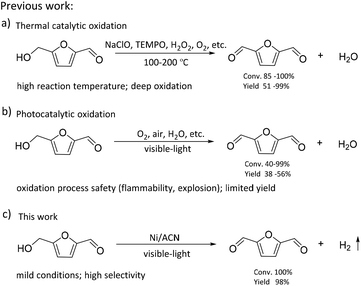
The consumption of fossil resources and the deteriorating environment have urged us to look for renewable resources to solve the above problems. As a renewable carbon-containing resource, biomass has been the focus of numerous studies. Biomass has been developed rapidly in recent years for its abundance, renewability, and global availability.1–4 5-Hydroxymethylfurfural (HMF), produced from the dehydration of C6 carbohydrates, is one of the most important platform chemicals.5 It is deemed as a vital building block for connecting biomass resources and the fossil fuel industry.6,7 HMF can be further converted into a series of high-value chemicals such as 2,5-diformylfuran (DFF), 5-formylfuran carboxylic acid, and 2,5-furandicarboxylic acid (FDCA).8–11 Among these, DFF is regarded as a promising platform chemical. It is an important precursor of furan-based biopolymers, furan-urea resins, pharmaceuticals, antifungal agents, and so on.12–15 Moreover, DFF is a more stable crystalline compound than HMF. HMF is a hygroscopic compound and susceptible to aging and decomposition, which complicates its practical utilization in organic synthesis and industrial applications.16,17 Therefore, it is highly essential to develop green and efficient catalytic routes for the synthesis of DFF.In the previous studies, DFF was mainly obtained by converting HMF under high temperature conditions (Scheme 1), such as selective oxidation of HMF, using traditional inorganic oxidants (including BaMnO4, NaClO, 2,2,6,6-tetramethylpiperidine-1-oxide (TEMPO)) or green oxidants (including H2O2, air and oxygen).18–21 Amarasekara's group reported that using Mn(III)-salen as the catalyst, DFF could be efficiently synthesized from the selective oxidation of HMF in NaClO solution.22 However, consumption of stoichiometric oxidants and discharge of hazardous wastes are inevitable. Liu et al. found that the Fe2O3-promoted MnO2 catalyst showed superior performance in the oxidation of HMF to DFF in the presence of 1.5 MPa air at 110 °C.23 Nevertheless, high reaction temperature needs to consume more energy, which is not consistent with the purpose of green chemistry.
Recently, as shown in Scheme 1, visible-light-driven photocatalytic selective oxidation of alcohols into the corresponding aldehydes has attracted great attention due to its mild reaction conditions and merit to be driven by solar energy.24–28 Yang et al. found that decatungstate could catalyze the visible light-triggered oxidation of HMF at normal temperature and pressure, affording DFF and FDCA as the oxygenated products.29 However, poor catalytic efficiency and the use of strong acid additives limited the development of this protocol. Ma et al. disclosed that the bimetallic Au–Ru nanoparticles supported on a reduced graphene oxide catalyst exhibited remarkable activity for selective oxidation of HMF.30 Unfortunately, it raised a few unavoidable problems such as the use of high-cost noble metals and oxidation process safety (flammability, explosion). These photocatalytic oxidation systems are usually accompanied by serious by-reactions, such as deep oxidation,31 resulting in their much lower photocatalytic efficiency than most of the above thermal catalytic systems. Some studies reported that photocatalytic oxidation of biomass-derived compounds could be integrated with photocatalytic H2 production in aqueous media.32 This process utilizes the oxidation ability brought by the special valence band energy level of the photocatalyst to produce two types of products simultaneously: upgraded bioproducts and H2, without additional oxidants. Han et al. demonstrated that it was feasible to produce value-added bioproducts DFF and H2 from HMF, utilizing both excited electrons and holes generated by Ni/CdS nanosheets under visible light irradiation.33 Meng et al. designed a NiS/Zn3In2S6 dual-function photocatalytic system to obtain DFF with high selectivity. At the same time, the H2-evolution rate in HMF solution was also significantly higher than that in water.34 Battula et al. confirmed that a Pt-modified graphite carbonitride catalyst was also suitable for photocatalytic selective transformation of HMF into DFF while simultaneously generating H2.35 However, in this system, water is used as an electron acceptor, and HMF is used as a sacrificial agent; its primary oxidation product, DFF, could be further oxidized to carboxylic acid because of the presence of water.36 To achieve a stoichiometric splitting of HMF, the photocatalyst should be able to abstract hydrogen from the alcohol instead of water.
Oxygen-free methodologies (dehydrogenation) feature several advantageous points such as tolerance towards different functional groups and suppression over oxidation. Until now, only a few studies that focused on the dehydrogenation HMF to DFF have been reported. For example, Chatterjee et al. used a Ru/C catalyst to catalyze HMF dehydrogenation at high temperature, and supercritical CO2 fluid as a H2 acceptor, the reaction conditions were relatively harsh.37 Properties of large surface area, low cost, easy functionalization, visible light adsorption, plenty of nitrogen atoms or vacancies and high photocatalytic activity make graphitic carbon nitride (CN) one of the most promising catalysts for visible light photoredox catalysis.38–40 Mesoporous graphitic carbon nitride is widely used in water splitting, selective oxidation and photoredox catalytic organic transformations of organic molecules because of its facile synthesis and excellent photocatalytic reactivity.41,42 In this study, we used graphitic carbon nitride (CN) modified with non-noble metals as the photocatalyst to prepare DFF via the dehydrogenation of HMF. As shown in Scheme 1, the reaction was performed without any oxidizing agent or additive or any conventional hydrogen acceptor. The visible-light-driven CN possessed a suitable energy band structure, which could provide feasible redox potential for the conversion of HMF into DFF. Non-noble metal co-catalysts could significantly improve the separation and transfer efficiencies of the photogenerated charge carriers of the CN. Thus, our catalysts exhibited high photocatalytic performance for the dehydrogenation of HMF into DFF. Besides, the effects of solvent, reaction time, the light source of different wavelengths, and different synthetic strategies of catalysts on this dehydrogenation reaction were investigated, and the reaction conditions were optimized. At the same time, the dehydrogenation mechanism of the catalyst was studied through the control experiments and the characterization of catalysts.
Experimental
Preparation of graphitic carbon nitride
Mesoporous graphitic carbon nitride was synthesized based on the previous work.43 Briefly, about 10 g urea were dissolved in a solution of 0.2 M HCl solution (15 mL) and ethanol (13 mL) under vigorous stirring, and tetraethyl orthosilicate (8 mL) was then slowly added to the above solution drop by drop. After stirring vigorously at room temperature for 3 h, the mixture was heated under a vacuum for solvent evaporation and then dried at 100 °C for about 12 h. The obtained white solid was heated at 550 °C for 4 h (heating rate: 2.5 °C min−1) under a nitrogen atmosphere. Subsequently, hydrofluoric acid was used to remove SiO2. Then, the obtained pale-yellow solid was washed with water and ethanol several times and dried at 80 °C for about 12 h. The pale-yellow solid (about 4 g) was finally obtained and denoted as ACN.The graphitic carbon nitride was synthesized based on the previous work.44 About 10 g urea or melamine was directly heated at 550 °C for 4 h (heating rate: 2.5 °C min−1) under a nitrogen atmosphere, giving a pale-yellow solid. Among them, the support prepared from urea was named BCN, and the support prepared from melamine was named CCN.
Preparation of Ni/ACN, Ni/BCN, Ni/CCN, Fe/ACN, and Co/ACN
The Ni/ACN photocatalysts were synthesized by the photodeposition method. In detail, the prepared ACN sample (150 mg) was dispersed in 50 mL dichloroethane solution, containing 18 mg NiCl2·6H2O and 3.2 mL methanol. Then, the system was evacuated and flushed with nitrogen to replace the residual air. This suspension was stirred and irradiated for 12 h under 390 nm light. After that, the product was filtered and washed with distilled water, and finally dried in a vacuum at 60 °C overnight. A series of catalysts could be synthesized by changing the types of metal precursors and supports, which were denoted as Ni/ACN, Ni/BCN, Ni/CCN, Fe/ACN, and Co/ACN, respectively.General procedure for photocatalytic reactions
The photocatalytic hydrogen production was performed in a 10 mL reaction tube. Specific steps: 0.05 mmol HMF and 10 mg Ni/ACN were dispersed in acetonitrile (MeCN) solution (1 mL). This system was evacuated and flushed with nitrogen to replace the residual air. Then, the photocatalytic system was irradiated under 390 nm light and magnetic stirring.A recycling experiment of the Ni/ACN photocatalyst was also carried out, maintaining the same reaction conditions as those described above, except using the recovered catalyst. For each time, the used catalyst was separated from the reaction system by centrifugation. The obtained catalyst was then washed with methanol a few times and dried at 60 °C overnight, before its reuse in another run.
The target product DFF was determined by NMR and HPLC as shown in Fig. S5 and S6.† The quantitative analysis of reactants and products was carried out by HPLC equipped with a C18AQ column using an eluent consisting of 30% acetonitrile and 70% trifluoroacetic acid aqueous solution at a flow rate of 1 mL min−1. The HMF conversion and DFF yield were calculated as follows:
The apparent quantum efficiency (AQE) was measured under the same photocatalytic reaction conditions. The number of incident photons was measured by iron(III) potassium oxalate trihydrate [potassium tris(oxalato)ferrate(III) trihydrate] (K3[Fe(C2O4)3]·3H2O), photoreduction (Hatchard–Parker actinometer, commonly called ferrioxalate actinometer). The AQE was calculated according to the following formula.
Results and discussion
The Ni/ACN photocatalyst was synthesized from a mixture of precursors ACN, NiCl2, and methanol by the photodeposition method (Fig. 1A). The morphology and element distribution of these catalysts are revealed by SEM and TEM. As seen in Fig. 1B, ACN has many loose holes. In the TEM image of the catalysts before and after loading, the ultra-thin sheets and metal particles can be seen on the ACN (Fig. 1C and D). To illustrate the composition of Ni/ACN, the mapping images (Fig. 1F, G, H and I) show the element distribution of Ni/ACN. The results show that Ni was successfully supported on the ACN, and the dispersion was uniform without agglomeration. A small amount of O element is present, which may be the adsorbing oxygen of the catalyst surface. Ni element content measured by EDS in this part of Ni/ACN (Fig. 1I) is 0.16 wt%, and the overall supported Ni content measured by ICP-OES is also 0.16 wt%, which further proves the successful loading of Ni.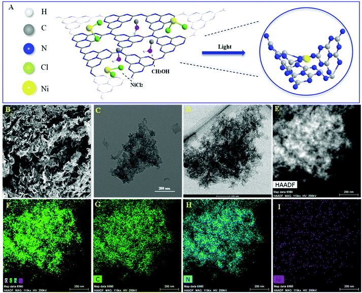 | ||
| Fig. 1 Illustration of preparation of Ni/ACN (A), SEM and TEM of ACN (B and C), TEM of Ni/ACN (D and E) and element mapping images of Ni/ACN (F): C element (G), N element (H) and Ni element (I). | ||
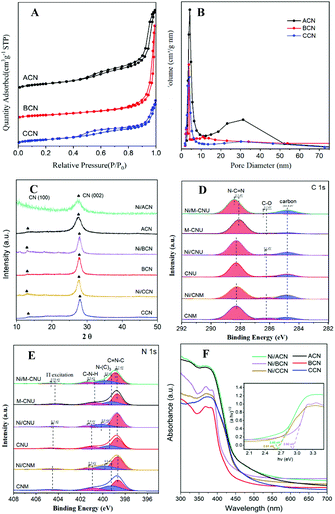
Fig. 2A shows the N2 adsorption–desorption isotherms of ACN, BCN, and CCN. The three samples exhibit the type IV isotherm with hysteresis in the range of 0.45–0.99P/P0, indicating that they have a mesoporous structure. As shown in the BJH pore size distribution diagram (Fig. 2B), the pore size distribution of the catalysts is between 2 and 50 nm, which further illustrates the mesoporous properties of the three types of catalysts. Among them, ACN has the most mesopores, and the other two pores are mostly concentrated in the near micropore size. The layered structure with mesopores is expected to provide more active sites for the reactants and promote the separation of electron–hole pairs, improving the quantum efficiency of the photocatalytic reaction. Moreover, the specific surface area of ACN is much higher than others (Table 1), which increases the accessibility of the reaction.
In addition, XRD and XPS show the interaction between Ni and supports. In XRD (Fig. 2C), there is no obvious difference between the three types of supports. The main peaks of CN were detected at around 12.8° and 27.3°, characteristic of the typical interplanar distance between nitride pores and the stacking peak of pi-conjugated CN layers, respectively.45 After the addition of Ni, there were no diffraction peaks related to Ni. This may be because the loading amount of Ni is too small. However, the distance between the crystal planes and the intensity of the diffraction peaks of the catalysts have some changes. Significantly, close observation shows that the diffraction peak intensity of Ni/ACN decreased, and the diffraction peak of the CN (100) crystal plane disappeared. Meanwhile, the diffraction peak of the (002) crystal plane changed from 27.72° to 27.26°, corresponding to an increase in the interplane stacking distance from 0.321 nm to 0.326 nm. The above proves that the loading of the metal affects the interaction between the CN layers, which leads to the disorder of the graphite structure.
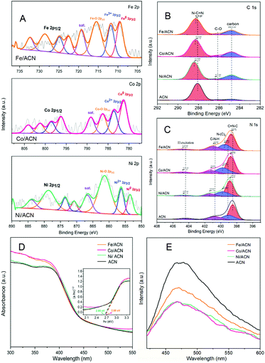
After Ni loading, the changes in the electronic binding energy of C and N elements in CN were analyzed. In the C 1s XPS spectra (Fig. 2D), the peak of 284.8 eV is the carbon correction peak. 286.1 eV corresponds to the C–O peak, formed by adsorbing trace amounts of O2 after exposure to air. The peak of 288.3 eV corresponds to the sp2 hybrid structure (N![[double bond, length as m-dash]](https://www.rsc.org/images/entities/char_e001.gif) C–N). In the N 1s XPS spectra (Fig. 2E), all of the catalysts have four peaks at 398.5 eV, 399.8 eV, 401.1 eV and 404.5 eV, which can be related to sp2 hybridized C
C–N). In the N 1s XPS spectra (Fig. 2E), all of the catalysts have four peaks at 398.5 eV, 399.8 eV, 401.1 eV and 404.5 eV, which can be related to sp2 hybridized C![[double bond, length as m-dash]](https://www.rsc.org/images/entities/char_e001.gif) N–C, sp3 hybridized N–(C)3, –NHX and the charge effect caused by π electron excitation.46–48 The surface electron binding energies of C and N elements of the three samples are not much different. After loading Ni, the peaks in CN shifted to the direction of high binding energy. This may be due to the strong interaction between Ni and CN. Due to the difference in the Fermi level between CN and Ni, electrons in CN spontaneously moved to the surface of Ni nanoparticles, resulting in a decrease in the electron density on the surface of N atoms.49,50 Also, taking Ni/ACN as an example, the intensity ratio of N(sp2)/N(sp3) decreased from 1.97 to 1.28 after the addition of Ni, and the charge effect peak (404.5 eV) shifted, indicating that the modification of Ni for CN can change the ordered structure of CN nanolayers, which may lead to an increase in catalyst defects.51 The result is mutually corroborated by the XRD analysis result.
N–C, sp3 hybridized N–(C)3, –NHX and the charge effect caused by π electron excitation.46–48 The surface electron binding energies of C and N elements of the three samples are not much different. After loading Ni, the peaks in CN shifted to the direction of high binding energy. This may be due to the strong interaction between Ni and CN. Due to the difference in the Fermi level between CN and Ni, electrons in CN spontaneously moved to the surface of Ni nanoparticles, resulting in a decrease in the electron density on the surface of N atoms.49,50 Also, taking Ni/ACN as an example, the intensity ratio of N(sp2)/N(sp3) decreased from 1.97 to 1.28 after the addition of Ni, and the charge effect peak (404.5 eV) shifted, indicating that the modification of Ni for CN can change the ordered structure of CN nanolayers, which may lead to an increase in catalyst defects.51 The result is mutually corroborated by the XRD analysis result.
Comparing the UV-Vis absorption performance of the catalysts (Fig. 2F), all three supports have good absorption in the wavelength range of 300 to 400 nm. According to the Kubelka–Munk formula, the band gaps of Ni/ACN, Ni/BCN, and Ni/CCN are 2.7, 2.9, and 2.6 eV, respectively. The reduction of the bandgap increases the range of light absorption, and the electron–hole pairs are easier to recombine.
Subsequently, XPS was also used to study the interaction between different metals and ACN on Ni/ACN, Fe/ACN, and Co/ACN (Fig. 3A, B and C). The peak at 853.5 eV was Ni0. And the peak at 856.3 eV was Ni2+, which may be due to the incomplete reduction of NiCl2 during the photodeposition process. The peak of Ni–O (861.4 eV) may be caused by the oxidation of the Ni surface. It should be noted that XPS usually characterizes the elements on the surface of the sample, so there was a large number of Ni–O. Besides, similar to the result of Ni-modified CN, after loading Fe/Co, the peaks in CN all shifted to the direction of high binding energy. Namely, during the process of three types of non-noble metals modifying CN, a strong interaction occurred. It made the electrons in CN move to the surface of metal nanoparticles spontaneously.
The process of modifying CN with non-noble metals changed the optical properties of CN. In the UV-vis spectra (Fig. 3D), the change is a little. However, as shown in Fig. 3E, there is a significant decrease in the PL intensity of ACN after metal modification, indicating that metal species promote the migration of photogenerated carriers and inhibit the recombination of electron–hole pairs. Among the series of catalysts, the modification results of Ni and Co on CN are the most obvious.
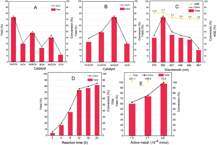
Different non-noble metal catalysts such as Fe, Co, and Ni loaded on different supports were screened for the reaction and the results are shown in Fig. 4A and B. Under the same reaction conditions (light wavelength = 390 nm; solvent = MeCN; reaction time = 12 h under a nitrogen atmosphere at room temperature and atmospheric pressure), the catalytic activity strongly depended on the metal as well as the support used. The three types of supports ACN, BCN, and CCN all had a little catalytic activity for the dehydrogenation of HMF.
Among them, ACN had the best reaction performance, which may be related to its largest specific surface area, unique porous structure and the strongest ultraviolet light absorption among the three types of supports. After the addition of metal cocatalysts, the catalytic activity had greatly improved. In particular, it showed a considerable HMF conversion on Ni/ACN, and the target product selectivity could reach up to 97%. Combined with XPS data analysis, Ni had the strongest interaction with ACN. Among the different metals supported on ACN, Ni/ACN had the best activity and achieved high selectivity for the target product. Fe and Co had worse activity, with the conversion of HMF being about 39% and 50%. The difference of active metals may be related to the utilization efficiency of the photo-generated carriers.
To explore the optimal reaction conditions, the influence of the wavelength of incident light on the HMF dehydrogenation system was studied. Fig. 4C shows the catalysis results under different light sources (wavelength varied from 370 to 467 nm) on Ni/ACN. Corresponding to the results of UV-vis absorption performance (Fig. 3D), the highest HMF conversion and DFF yield were achieved under 390 nm wavelength light source, and the AQE reached a peak of 11.7%.
The reaction time was extended from 2 hours to 24 hours to study the catalytic performance over time (Fig. 4D). With time, the conversion of HMF increased from 6% (2 hours) to 85% (24 hours), and the selectivity of DFF hardly changed during the reaction. There were no other by-products in the detectable range.
Furthermore, we studied the effect of the amount of catalyst on the dehydrogenation process. Without changing other parameters, it shows an increasing trend of the conversion and selectivity of DFF with the amount of active metal in Ni/ACN being increased from 1.4 × 10⁻⁴ mmol to 6.8 × 10⁻⁴ mmol (corresponding to the increase in catalyst dosage from 5 mg to 25 mg, Fig. 4E). Finally, it could achieve the complete conversion of HMF, and even an excessive amount of catalyst did not inhibit the dehydrogenation process. We compared the catalyst turnover (TON) under different catalyst dosages. For the amount of active metal 1.4 × 10⁻⁴, 2.7 × 10⁻⁴, and 6.8 × 10⁻⁴ mmol, the corresponding TON was 231.1, 139.4, and 73.4, respectively. It could be seen from TON that even a little amount of metal loading (0.16 wt%) could obtain a high conversion, that is, Ni/ACN had excellent catalytic activity for the dehydrogenation system of HMF. Besides, as we can see, DFF was the sole product by the dehydrogenation of HMF on Ni/ACN. Ni/ACN was the most suitable catalyst under the applied conditions to achieve excellent selectivity of DFF with complete conversion.
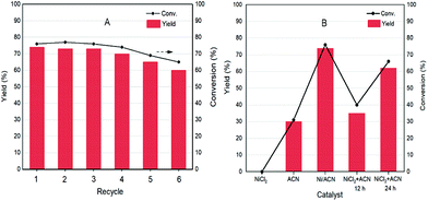
As a heterogeneous catalyst, recycling of Ni/ACN is one of the most important criteria considering the environmental and economic sustainability of the process. The used Ni/ACN catalyst was subjected to recycling and the results are shown in Fig. 5A. The used catalyst maintained catalytic activity in the first three cycles, and the conversion dropped by about 10% in the fifth cycle, the selectivity of DFF remained unchanged. The content of active metal leached in the reaction solution after one cycle was detected. The result of ICP-OES showed that the amount of metal leached in the reaction solution was 4% of the original load, indicating that Ni/ACN had excellent stability.
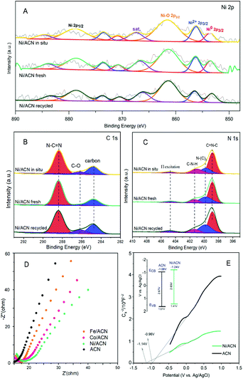
To explore the principle of the photodeposition method for preparing the catalyst and the synergistic mechanism of the metal and CN in the HMF dehydrogenation system, the catalyst was prepared in situ based on the photodeposition method and was named Ni/ACN-in situ. The calculated amounts of ACN and NiCl2 were directly incorporated into the active reaction substrate, the substrate HMF was used as the primary alcohol for reducing metal, and the light source that provided energy for the reaction also provided energy for reducing metal. During the reaction, HMF was used as a reducing agent to continuously reduce Ni metal particles to produce Ni/ACN, and at the same time, HMF was converted to DFF. The newly formed Ni/ACN further catalyzed the dehydrogenation of HMF to DFF. The result of the reaction is shown in Fig. 5B. No target product DFF was detected in the reaction solution with NiCl2 added alone. The pure ACN had little activity. The activity of the Ni/ACN-in situ was gradually increased after mixing for 12 h in the reaction, and it took 24 h to have considerable catalytic performance. Therefore, a single NiCl2 or ACN could not be used as a suitable catalyst in the HMF dehydrogenation system. Only the Ni species coordinated with C and N could cooperate with the support to catalyze the dehydrogenation of HMF to produce DFF. XPS of the catalyst prepared in situ is shown in Fig. 6. The Ni/ACN catalyst could be successfully prepared by the in situ method, in which the component of Ni0 was less than it was in Ni/ACN prepared by the photodeposition method (Table S2†). At the same time, a small amount of Cl residue on the surface of the catalyst was detected, and its content was about 40% of the Ni atom content. The above results indicated that in the Ni/ACN prepared by the in situ method, part of Ni was reduced to Ni0 to become active sites, and part was still NiCl2 species, which may be the reason why its activity was not as good as the photodeposition catalyst.
The electrochemical impedance (EIS) and Mott–Schottky (MS) performances of a series of catalysts were tested to determine the migration mechanism of photogenerated carriers. The radius of the semicircle in the high-frequency region of the EIS map (Fig. 6D) corresponded to the size of the charge transfer resistance and the separation efficiency of the photogenerated carriers.52 The radius of the non-noble metal-modified catalyst was reduced, indicating that the modification of metal reduced the resistance of electron transfer and promoted the transfer of photogenerated electrons. Among them, the radius of Ni/ACN was the smallest, which corresponded to the result of the activity. The MS test was carried out in Na2SO4 solution, and the semiconductor energy band structure of the catalyst after adding the metal cocatalyst Ni could be calculated, which determined the redox ability in the photocatalytic reaction process. As shown in Fig. 6E, the slopes of the MS curves of the samples were all positive, which indicated that they were all N-type semiconductors. The calculation showed that the flat-band potential Vfb of ACN was −0.96 V (vs. Ag/AgCl), and the Ni/ACN Vfb was −1.14 V. The corresponding conduction band potential ECB calculated by the formula Vfb(vs. NHE) = Vfb(vs. Ag/AgCl) + Eϴ(Ag/AgCl, vs. NHE) was −1.06 V, −1.24 V (vs. NHE, pH = 6.8). The band gaps Eg of the catalysts ACN and Ni/ACN obtained by UV-vis were 2.67 and 2.65 eV. According to the formula Eg = EVB − ECB, the valence band potential EVB was 1.61 V and 1.41 V, respectively (vs. NHE, pH = 6.8).53,54 It could find that the valence charge potential of the catalyst after the modification of Ni was lower than that of pure CN, that is, it had a stronger electron-donating ability, which was manifested as a stronger reaction activity in the HMF dehydrogenation system.
Based on the analysis of the above-mentioned energy band structure, the migration mechanism of photogenerated carriers could be inferred. The Fermi level Ef of CN with N-type semiconductor characteristics is close to the flat band potential,55 the work function of Ni was 5.15 eV, so that its Ef value was lower than Ef CN, as shown in Fig. 7. Therefore, during the Ni deposition process, the electrons on the CN surface spontaneously migrated to the Ni surface, and the Fermi levels of the two gradually moved to the middle until they reached equilibrium. This also explained why the Ni/ACN N 1s XPS spectrum in Fig. 2E shifted to a higher energy level relative to ACN. After reaching equilibrium, a Schottky junction could be formed between Ni and CN, and the surface of the Ni nanosphere near the interface was negatively charged, while the surface layer of CN was positively charged, thus forming a built-in electric field from CN to Ni atoms. At the same time, a high potential energy zone was formed at the interface, which prevented electrons in CN from continuously flowing into the surface of Ni. Under visible-light illumination, Ni was excited, the excited state electrons transferred from the low energy band to the high energy band. Then under the action of the built-in electric field, it quickly migrated to the conduction band of CN to inhibit the photogenerated electron–hole pair complex. Due to the existence of the Schottky barrier, the photogenerated electrons could also be prevented from returning to the surface of Ni, thereby effectively improving the utilization efficiency of photogenerated electrons.
In addition, we also did hydrogen verification experiment (Fig. S9†) to confirm the production of hydrogen during the dehydrogenation of HMF. In the verification experiment, hydrogen gas was only detected qualitatively and it was not possible to determine the actual stoichiometry of this product related to the production of DFF. A series of scavengers have also been studied (Fig. S10†). When KI (h+ scavenger) was added, the holes were quenched and HMF was no longer transformed, indicating that the photogenerated holes played a leading role in the reaction. However, when C6H5NO2 (e− scavenger) was added, the electrons were quenched, although the conversion was greatly reduced, but the reaction was still going on. Even though the photo-generated electrons also played an important role in the reaction, the reduction of electrons theoretically inhibited the reaction process. It was possible that the addition of an electron scavenger effectively separated the photo-generated holes from the photo-generated electrons, and reduced the recombination efficiency of electrons and holes, thereby promoting the reaction.
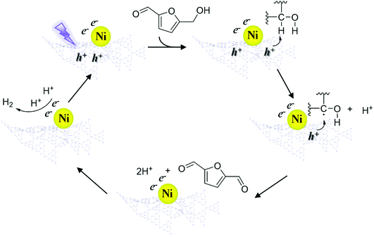
According to the above results, a speculative photocatalytic mechanism (Scheme 2) for the dehydrogenation of HMF was proposed. When CN was irradiated with photons with energy greater than its bandgap energy, light-excited electrons (e−) and holes (h+) were generated, and then the electrons migrated from the conduction band of CN to coordinated Ni. Similar to the mechanism speculated in previous work,56 at the start of the reaction, h+ on CN activated HMF, forming free radicals and proton (H+). Then HMF free radicals were further activated by h+ to obtain DFF and H+. Afterwards, two H+ contacted e− on Ni to produce H2, and the catalyst entered the next cycle after the H2 was desorbed. In the reaction process, the supported non-noble metals mainly played a role in improving the utilization efficiency of carrier photogenerated electrons and accelerating the reaction process.
Conclusions
In conclusion, we developed an efficient photocatalytic methodology free from any kind of oxidant or additive, or conventional hydrogen acceptor for dehydrogenation of a biomass-based platform 5-hydroxymethylfurfural. The developed method is promising in the conversion of HMF to DFF with high selectivity. Key to success is the interaction between the non-noble metal and graphitic carbon nitride. The non-noble metal cocatalyst can significantly improve the separation and transfer efficiencies of the photogenerated charge carriers in CN to improve the utilization efficiency of carrier photogenerated electrons and accelerate the reaction process. We believed that, after further optimization of the semiconductor and cocatalyst, we can extend the photocatalytic dehydrogenation methodology to other organic transformation reactions.Conflicts of interest
The authors declare no conflict of interest.Acknowledgements
This work was supported by the National Key R&D Program of China (2018YFB1501604), the Strategic Priority Research Program of the CAS (XDA21060101) and the National Natural Science Foundation of China (21875239, 21732006, 51821006, and 51961135104). The authors thank the Hefei Leaf Biotech Co., Ltd and Anhui Kemi Machinery Technology Co., Ltd for free samples and equipment that benefited our ability to conduct this study.Notes and references
- N. Fabian, Nature, 2015, 519, 27–29 CrossRef CAS PubMed.
- K. L. Law and R. C. Thompson, Science, 2014, 345, 144–145 CrossRef CAS PubMed.
- A. Corma, S. Iborra and A. Velty, Chem. Rev., 2007, 107, 2411–2502 CrossRef CAS PubMed.
- C. O. Tuck, E. Perez, I. T. Horvath, R. A. Sheldon and M. Poliakoff, Science, 2012, 337, 695–699 CrossRef CAS PubMed.
- J. N. Chheda, G. W. Huber and J. A. Dumesic, Angew. Chem., Int. Ed., 2007, 46, 7164–7183 CrossRef CAS PubMed.
- Z. Zhang, J. Song and B. Han, Chem. Rev., 2017, 117, 6834–6880 CrossRef CAS PubMed.
- E. J. Cho, L. T. P. Trinh, Y. Song, Y. G. Lee and H.J. Bae, Bioresour. Technol., 2020, 298, 122386 CrossRef CAS PubMed.
- C. Xu, E. Paone, D. Rodrıíguez-Padrón, R. Luque and F. Mauriello, Chem. Soc. Rev., 2020, 49, 4273–4306 RSC.
- L. Hu, L. Lin, Z. Wu, S. Zhou and S. Liu, Renewable Sustainable Energy Rev., 2017, 74, 230–257 CrossRef CAS.
- H. Wang, C. Zhu, D. Li, Q. Liu, J. Tan, C. Wang, C. Cai and L. Ma, Renewable Sustainable Energy Rev., 2019, 103, 227–247 CrossRef CAS.
- R. J. Van Putten, J. C. Van Der Waal, E. De Jong, C. B. Rasrendra, H. J. Heeres and J. G. De Vries, Chem. Rev., 2013, 113, 1499–1597 CrossRef CAS PubMed.
- G. Lv, H. Wang, Y. Yang, T. Deng, C. Chen, Y. Zhu and X. Hou, ACS Catal., 2015, 5, 5636–5646 CrossRef CAS.
- J. Artz, S. Mallmann and R. Palkovits, ChemSusChem, 2015, 8, 672–679 CrossRef CAS PubMed.
- Z. Zhang, Z. Yuan, D. Tang, Y. Ren, K. Lv and B. Liu, ChemSusChem, 2014, 7, 3496–3504 CrossRef CAS PubMed.
- B. Karimi, H. M. Mirzaei and E. Farhangi, ChemCatChem, 2014, 6, 758–762 CrossRef CAS.
- V. R. Battula, A. Jaryal and K. Kailasam, J. Mater. Chem. A, 2019, 7, 5643–5649 RSC.
- K. I. Galkin, E. A. Krivodaeva, L. V. Romashov, S. S. Zalesskiy, V. V. Kachala, J. V. Burykina and V. P. Ananikov, Angew. Chem., Int. Ed., 2016, 55, 8338–8342 CrossRef CAS PubMed.
- Z. Yang, J. Deng, T. Pan, Q. Guo and Y. Fu, Green Chem., 2012, 14, 2986–2989 RSC.
- J. F. Nie, J. H. Xie and H. C. Liu, J. Catal., 2013, 301, 83–91 CrossRef CAS.
- J. Ma, Z. Du, J. Xu, Q. Chu and Y. Pang, ChemSusChem, 2011, 4, 51–54 CrossRef CAS PubMed.
- F. L. Grasset, B. Katryniok, S. Paul, V. Nardello-Rataj, M. Pera-Titus, J. M. Clacens, F. D. Campo and F. Dumeignil, RSC Adv., 2013, 3, 9942–9948 RSC.
- A. S. Amarasekara, D. Green and E. McMillan, Catal. Commun., 2008, 9, 286–288 CrossRef CAS.
- H. Liu, X. Cao, J. Wei, W. Jia, M. Li, X. Tang, X. Zeng, Y. Sun, T. Lei, S. Liu and L. Lin, ACS Sustainable Chem. Eng., 2019, 7, 7812–7822 CrossRef CAS.
- I. Krivtsov, E.I. Garcia-Lopez, G. Marci, L. Palmisano, Z. Amghouz, J. R. Garcia, S. Ordonez and E. Diaz, Appl. Catal., B, 2017, 204, 430–439 CrossRef CAS.
- Q. Wu, Y. M. He, H. L. Zhang, Z. Y. Feng, Y. Wu and T. H. Wu, Mol. Catal., 2017, 436, 10–18 CrossRef CAS.
- H. Zhang, Z. Feng, Y. Zhu, Y. Wu and T. Wu, J. Photochem. Photobiol., A, 2019, 371, 1–9 CrossRef CAS.
- H. Zhang, Q. Wu, C. Guo, Y. Wu and T. Wu, ACS Sustainable Chem. Eng., 2017, 5, 3517–3523 CrossRef CAS.
- S. Yurdakal, B. S. Tek, O. Alagöz, V. Augugliaro, V. Loddo, G. Palmisano and L. Palmisano, ACS Sustainable Chem. Eng., 2013, 1, 456–461 CrossRef CAS.
- B. Yang, W. Hu, F. Wan, C. Zhang, Z. Fu, A. Su, M. Chen and Y. Liu, Chem. Eng. J., 2020, 396, 125345 CrossRef CAS.
- B. Ma, Y. Wang, X. Guo, X. Tong, C. Liu, Y. Wang and X. Guo, Appl. Catal., A, 2018, 552, 70–76 CrossRef CAS.
- S. Yurdakal, B. S. Tek, O. Alagöz, V. Augugliaro, V. Loddo, G. Palmisano and L. Palmisano, ACS Sustainable Chem. Eng., 2013, 1, 456–461 CrossRef CAS.
- J. Li, Y. Li, M. Qi, Q. Lin, Z. Tang and Y. Xu, ACS Catal., 2020, 10, 6262–6280 CrossRef CAS.
- G. Han, Y. Jin, R. Burgess, N. Dickenson, X. Cao and Y. Sun, J. Am. Chem. Soc., 2017, 139, 15584–15587 CrossRef CAS PubMed.
- S. Meng, H. Wu, Y. Cui, X. Zheng, H. Wang, S. Chen, Y. Wang and X. Fu, Appl. Catal., B, 2020, 266, 118617 CrossRef CAS.
- V. R. Battula, A. Jaryal and K. Kailasam, J. Mater. Chem. A, 2019, 7, 5643–5649 RSC.
- Z. Chai, T. Zeng, Q. Li, L. Lu, W. Xiao and D. Xu, J. Am. Chem. Soc., 2016, 138, 10128–10131 CrossRef CAS PubMed.
- M. Chatterjee, T. Ishizaka, A. Chatterjee and H. Kawanami, Green Chem., 2017, 19, 1315–1326 RSC.
- Y. Wang, X. Wang and M. Antonietti, Angew. Chem., Int. Ed., 2012, 51, 68–89 CrossRef CAS PubMed.
- L. Wang, K. Wang, T. He, Y. Zhao, H. Song and H. Wang, ACS Sustainable Chem. Eng., 2020, 8, 16048–16085 CrossRef CAS.
- W. Ong, L. Tan, Y. H. Ng, S. Yong and S. Chai, Chem. Rev., 2016, 116, 7159–7329 CrossRef CAS PubMed.
- R. Zhu, G. Zhou, J. Teng, X. Li and Y. Fu, ChemSusChem, 2020, 13, 5248–5255 CrossRef CAS PubMed.
- R. Zhu, G. Zhou, J. Teng, W. Liang, X. Li and Y. Fu, Green Chem., 2021, 23, 1758–1765 RSC.
- L. Shi, L. Lin, F. Wang, M. Liu, K. Chen, K. Sun, N. Zhang and J. Sun, ACS Sustainable Chem. Eng., 2015, 3, 3412–3419 CrossRef CAS.
- M. M. C. H. van Schie, W. Zhang, F. Tieves, D. S. Choi, C. B. Park, B. O. Burek, J. Z. Bloh, I. W. C. E. Arends, C. E. Paul, M. Alcalde and F. Hollmann, ACS Catal., 2019, 9, 7409–7417 CrossRef CAS.
- S. Ye, R. Wang, M. Wu and Y. Yuan, Appl. Surf. Sci., 2015, 358, 15–27 CrossRef CAS.
- H. Wang, Z. Sun, Q. Li, Q. Tang and Z. Wu, J. CO2 Util., 2016, 14, 143–151 CrossRef CAS.
- J. Li, B. Shen, Z. Hong, B. Lin, B. Gao and Y. Chen, Chem. Commun., 2012, 48, 12017–12019 RSC.
- D. J. Martin, K. Qiu, S. A. Shevlin, A. D. Handoko, X. Chen, Z. Guo and J. Tang, Angew. Chem., Int. Ed., 2014, 53, 9240 CrossRef CAS PubMed.
- Q. Li, Z. Sun, H. Wang and Z. Wu, J. CO2 Util., 2018, 28, 126–136 CrossRef CAS.
- Z. Sun, S. Wang, Q. Li, M. Lyu, T. Butburee, B. Luo, H. Wang, J. M. T. A. Fischer, C. Zhang, Z. Wu and L. Wang, Adv. Sustainable Syst., 2017, 1, 1700003 CrossRef.
- C. Xie, D. Yan, H. Li, S. Du, W. Chen, Y. Wang, Y. Zou, R. Chen and S. Wang, ACS Catal., 2020, 10, 11082–11098 CrossRef CAS.
- E. Cui and G. Lu, Int. J. Hydrogen Energy, 2014, 39, 7672–7685 CrossRef CAS.
- W. Ong, L. K. Putri, Y. Tan, L. Tan, N. Li, Y. Ng, X. Wen and S. Chai, J. Nano Res., 2017, 10, 1673–1696 CrossRef CAS.
- X. An, K. Li and J. Tang, ChemSusChem, 2014, 7, 1086–1093 CrossRef CAS PubMed.
- Y. Qiu, K. Yan, H. Deng and S. Yang, Nano Lett., 2012, 12, 407–413 CrossRef CAS PubMed.
- Y. Xu, C. Du, C. Zhou and S. Yang, Chem. Commun., 2020, 56, 7171–7174 RSC.
Footnotes |
| † Electronic supplementary information (ESI) available. See DOI: 10.1039/d1gc01286j |
| ‡ These authors contributed equally to this work. |
| This journal is © The Royal Society of Chemistry 2021 |



![[thin space (1/6-em)]](https://www.rsc.org/images/entities/char_2009.gif)
