Surface-modified metal sulfides as stable H2-evolving photocatalysts in Z-scheme water splitting with a [Fe(CN)6]3−/4− redox mediator under visible-light irradiation†
Takashi
Shirakawa
a,
Masanobu
Higashi
 *a,
Osamu
Tomita
 a and
Ryu
Abe
*ab
aGraduate School of Engineering, Kyoto University, Katsura, Nishikkyo-ku, Kyoto, 615-8510 Japan. E-mail: east@scl.kyoto-u.ac.jp; ryu-abe@scl.kyo-u.ac.jp
bJST-CREST, 7 Gobancho, Chiyoda-ku, Tokyo, 102-0076 Japan
First published on 4th May 2017
Abstract
Z-scheme splitting of water into H2 and O2 was achieved using K2[CdFe(CN)6]-modified metal sulfides as H2-evolving photocatalysts combined with an appropriate O2-evolution system (CoOx-loaded TaON photoanode) in the presence of [Fe(CN)6]3−/4− as an electron mediator. Pt/CdS showed high activity (67.7 μmol h−1) for H2 evolution in borate buffer solution containing [Fe(CN)6]4− as an electron donor under visible-light irradiation. A cyano complex containing [Fe(CN)6]4− and Cd2+, which efficiently scavenged photogenerated holes and effectively facilitated the oxidation of [Fe(CN)6]4− to [Fe(CN)6]3−, was formed on the CdS surface in the reaction. Modification of other metal sulfides, such as ZnIn2S4 and CdIn2S4, with the cyano complex K2[CdFe(CN)6] significantly improved their rates of H2 evolution (ZnIn2S4: 4.8 → 15 μmol h−1; CdIn2S4: 0.8 → 6 μmol h−1) in the presence of [Fe(CN)6]4− and an appropriate O2-evolution system (CoOx-loaded TaON photoanode), enabling Z-scheme water splitting.
Introduction
Photocatalytic water splitting using semiconductor materials has attracted considerable attention due to its potential for the clean production of H2 from water utilizing solar energy.1 Since nearly half the solar energy incident on the Earth's surface lies in the visible region, the efficient harvesting of visible light is essential for realizing practical, high-efficiency photocatalytic H2 production under natural sunlight. Various metal sulfides, especially cadmium sulfide (CdS), have been extensively studied as photocatalysts for visible-light-induced H2 production since the mid-1970s as many sulfides possess both the narrow bandgaps required for visible-light absorption and appropriate band levels for water splitting. For example, the conduction band minimum (CBM) and the valence band maximum (VBM) of CdS (bandgap: ca. 2.3 eV) have been reported as ca. −0.8 V and ca. 1.5 V vs. the SHE, which are thermodynamically sufficient for water reduction and oxidation, respectively. Another fascinating feature of such metal sulfides is the potential for band tuning via the formation of solid solutions, as demonstrated in binary CuGaS2–ZnS (i.e., (CuGa)1−xZn2xS2)2 and ternary ZnS–CuInS2–AgInS2 (i.e., (CuAg)xIn2xZn2(1−2x)S2) systems.3 However, the biggest drawback of such metal sulfides is their instability, which is attributed to the occurrence of self-oxidative deactivation. For example, it is well recognized that CdS is readily dissolved through photocorrosion in aqueous solutions, in which photogenerated holes preferentially oxidize S2− at the near-surface in the absence of an appropriate electron donor, as follows:4| CdS + 2h+ → Cd2+ + S |
Although highly efficient H2 production can proceed on Pt-loaded CdS particles in the presence of a strong, i.e., sacrificial, electron donor that can efficiently quench holes, such as S2−, SO3−, and triethanolamine,5 such reactions are basically irreversible and exothermic (i.e., downhill) in most cases. As for the oxidation of water, which requires four-electron abstraction (i.e., four-hole quenching), no steady O2 evolution on such metal sulfides has been demonstrated yet despite its thermodynamic plausibility, which may be attributed to the occurrence of self-oxidative deactivation. Thus, overall water splitting (i.e., simultaneous evolution of H2 and O2) has not yet been achieved using a metal sulfide semiconductor as a single photocatalyst.
One of the most reasonable and attractive strategies to achieve overall water splitting using such metal sulfides under visible light involves applying them to Z-scheme water splitting systems as H2-evolving photocatalysts.6 In Z-scheme water splitting systems, a H2-evolving photocatalyst and an O2-evolving photocatalyst are combined via a shuttle redox mediator; thus the requirement for a H2-evolving photocatalyst is significantly eased. The H2-evolving photocatalyst employed need only oxidize the reduced form of a redox couple to the corresponding oxidant; thus it does not need to oxidize water to O2. For example, Kudo et al. have recently demonstrated Z-scheme water splitting using the metal sulfide (CuGa)0.8Zn0.4S2 as a H2-evolving photocatalyst combined with BiVO4 (O2-evolving photocatalyst) via the redox complex [Co(terpy)3]3+/2+.2 They also demonstrated Z-scheme water splitting using reduced graphene oxide (RGO) as a solid electron mediator decorated with rutile TiO2 or BiVO4 as the O2-evolving photocatalyst in which only p-type metal sulfides such as CuGaS2, CuInS2, and Cu2ZnGeS4 work as the H2-evolving photocatalyst.7 Furthermore, Li et al. have reported a hybrid water-splitting system in which natural photosystem II (PSII) was utilized for O2 evolution combined with H2-evolving photocatalysts or photoanodes such as Rh-doped SrTiO3 or CdS via the [Fe(CN)6]3−/4− redox cycle. However, their report did not contain detailed results such as turnover numbers or information on the stability of CdS.8 Although several Z-scheme water splitting systems using metal sulfides have recently been reported, the number of suitable metal sulfides available is still limited. Thus, a versatile strategy that can endow metal sulfides with sufficient stability and high activity for H2 evolution in the presence of a redox couple is required in order to expand the availability of metal sulfide photocatalysts for overall water splitting.
A possible reason for the limitation of available metal sulfides for Z-scheme systems is the insufficient rate of oxidation of the reductant on the metal sulfide surface. Even though the VBM is thermodynamically sufficient for the oxidation of the reductant, photocorrosion and/or oxidative deactivation (e.g., formation of inactive oxide layers) occurs competitively if the oxidation rate of the reductant is insufficient. Therefore, the development of new and efficient catalysts that can facilitate the surface redox reactions and thereby suppress self-oxidative deactivation will mitigate the most significant drawback of metal sulfide photocatalysts, thus opening the way for achieving highly efficient Z-scheme water splitting under visible light.
In this paper, we introduce a new and versatile strategy for stabilizing not only CdS but also other metal sulfides such as ZnIn2S4 and CdIn2S4 as H2-evolving photocatalysts in Z-scheme water splitting mediated by the [Fe(CN)6]3−/4− redox couple. This strategy involves the formation of a thin protective and catalytic complex layer on the surface of the metal sulfides.
Experimental
Preparation of photocatalysts and photoelectrodes
Commercially available CdS (Alfa Aesar, 99.999%, hexagonal) was mainly used as the photocatalyst after calcination at 673 K for 4 h under Ar flow (20 mL min−1) to increase its crystallinity.9 For comparison, another commercial CdS (Aldrich, 98% mixed phase of hexagonal and cubic) was used after the same calcination procedure. No obvious change was observed in their XRD patterns after the calcination (Fig. S1†). Their particle sizes after calcination were confirmed to be 2–5 μm and 0.2–0.3 μm, respectively, as shown in Fig. S2.† The CdS obtained from Alfa Aesar was used unless otherwise stated.Particles of ZnIn2S4 and CdIn2S4 were prepared by a hydrothermal method.10 In a typical preparation of ZnIn2S4, 0.5 mmol of Zn(NO3)2·6H2O (Wako, 99%), 1.0 mmol of In(NO3)3·3H2O (Wako, 98%), and 4.0 mmol of CH3CSNH2 (Wako, 98%) were dissolved in Milli-Q water (75 mL). The pH of the obtained solution was adjusted to 2.0 with aqueous HCl (1 M). The solution was then transferred into a 100 mL Teflon-lined autoclave. The autoclave was sealed, heated at 433 K for 12 h, and cooled naturally to room temperature. The yellow precipitate produced was filtered, washed with Milli-Q water and then ethanol several times, and finally dried under vacuum at room temperature overnight. The obtained ZnIn2S4 powder was calcined at 1073 K for 4 h under Ar flow (20 mL min−1). In a typical preparation of CdIn2S4 particles, Cd(OAc)2·2H2O (Wako, 98%) and InCl3·4H2O (Nacalai Tesque, 95%) were used as starting materials, and subjected to the same procedure as that described for the preparation of ZnIn2S4. The X-ray powder diffraction (XRD) patterns of the obtained ZnIn2S4 and CdIn2S4 were in good agreement with those of the database (PDF no. 01-070-2639 and 00-027-0060, respectively, shown in Fig. S1†). Their particle sizes are 1–3 μm and 0.5–1 μm, respectively, as shown in Fig. S2.†
The CdS photoelectrodes were prepared on fluorine-doped tin oxide (FTO, AGC Fabritech) substrates by chemical bath deposition.11 The FTO substrate was immersed vertically in 50 mL of an aqueous solution containing NH3 (14%) and Cd(OAc)2·2H2O (5 mmol) for 1 min, followed by the addition of CH3CSNH2 (76.2 mmol). After holding the FTO in the mixed solution for 3 min at 343 K, the FTO was removed from the solution. Then the CdS-loaded FTO was washed with Milli-Q water, dried in air at room temperature, and then calcined at 673 K for 4 h under Ar flow (20 mL min−1).
For the preparation of ZnIn2S4 and CdIn2S4 photoelectrodes, an aqueous slurry of each sample was first prepared by mixing the synthesized particles (100 mg) and Milli-Q water (0.1 mL). The slurry was then spread on the FTO substrates, followed by air-drying and calcination at 473 K for 4 h under Ar flow (20 mL min−1). The area coated for all electrodes was set to ca. 1.5 × 4 cm2.
For the surface modification of the ZnIn2S4 and CdIn2S4 photoelectrodes, an aqueous solution of CdBr2 (10 wt% Cd) was applied to the electrode, followed by heating at 473 K for 30 min under Ar flow (20 mL min−1). Conversely, an aqueous solution of K2[CdFe(CN)6] was used for surface modification of the particulate samples using the same procedure as that outlined above.
Characterization
The prepared samples were characterized by means of XRD (Rigaku, Mini Flex II, X-ray source; Cu Kα) and attenuated total reflectance-Fourier transform infrared spectroscopy (ATR-FTIR, ATR; JASCO, ATR Pro One, FT-IR; JASCO, FT-4200) using a Ge prism. The background was measured without samples in air. The samples were also analyzed using X-ray photoelectron spectroscopy (XPS; ULVAC-PHI, ESCA5500) with a Mg Kα X-ray source (15 kV, 400 W) at less than 1 × 10⁻⁸ Torr. The electron take-off angle was set to 45 degrees. The binding energy determined by XPS was corrected with reference to the C 1s peak (284.6 eV) of each sample. The morphology was examined using scanning electron microscopy (SEM; KEYENCE, VE-9800), transmission electron microscopy (TEM; JEOL, JEM-2100F), and scanning transmission electron microscopy (STEM; JEOL, JEM-2100F).Photoelectrochemical measurements
The electrochemical cell used for photocurrent measurements comprised one of the prepared electrodes as the working electrode, a Ag/AgCl reference electrode, and a Pt wire as the counter electrode. A borate buffer (BB) solution was used as the electrolyte (80 mL), which was prepared by mixing an aqueous solution of boric acid (0.1 M) and an aqueous solution of KOH (0.1 M), as well as K4[Fe(CN)6] (5 mM). The pH values of the solutions were finally adjusted to 8 by adding aqueous KOH (0.1 mM). The solution was purged with Ar for over 20 min prior to measurement. The electrodes were irradiated with visible light using a 300 W Xe lamp (Cermax, LX-300F) equipped with a cutoff filter (L-42, Hoya) and a cold mirror (Kenko, CM-1) (400 nm < λ < 800 nm).Photocatalytic reactions
Particulate Pt was photodeposited onto the photocatalyst samples as a water reduction cocatalyst as follows: particles of CdS or CdIn2S4 (0.5 g) were stirred in an aqueous KOH solution (1.0 M, 150 mL) in which the required amount (1.0 wt% Pt) of H2PtCl6·6H2O was added as the Pt precursor. The suspension was irradiated with visible light for 3 h using a 300 W Xe lamp equipped with an L-42 cutoff filter and a cold mirror (400 nm < λ < 800 nm).12 In the case of the ZnIn2S4 sample, Pt was photodeposited in the BB solution (0.1 M, pH 8) containing K4[Fe(CN)6] (5 mM). The obtained catalysts were denoted as Pt/CdS, Pt/CdIn2S4, and Pt/ZnIn2S4, respectively. The average sizes of Pt particles loaded on CdS, CdIn2S4, and ZnIn2S4 are about 2–3 nm, 3 nm, and 2–4 nm (see Fig. S3† for TEM images). Typically, photocatalytic reactions were carried out using a Pyrex reactor connected to a closed gas-circulation system. Photocatalyst powder (50 mg) was suspended in 250 mL of an aqueous solution containing a sacrificial electron donor (mixture of 0.35 M Na2S and 0.25 M K2SO3) or reversible electron donors (5 mM NaI, FeCl2, and K4[Fe(CN)6]). In some cases, the BB solution (0.1 M, pH 8) containing 5 mM K4[Fe(CN)6] was used. After thorough degassing by the introduction of Ar (the system was filled with Ar gas to 10 kPa), the reaction solution was irradiated using a 300 W Xe lamp (Cermax, LX-300F) equipped with a cutoff filter (Hoya, L-42) and a cold mirror (Kenko, CM-1) (λ > 400 nm). The evolved gases were analyzed by online gas chromatography (Shimadzu GC-8A; thermal conductivity detector; column: 5 Å molecular sieves; Ar carrier). The amount of [Fe(CN)6]3− generated during the reaction was measured using a UV-Vis spectrophotometer (JASCO, V-650).The effect of pH on the H2-generation rate was also examined. In this case, the rate of H2 evolution was evaluated using a flow system as follows: a Pt/CdS sample (30 mg) was suspended in 150 mL of an aqueous solution containing K4[Fe(CN)6] (5 mM) as an electron donor. The pH was adjusted to 3, 5, 9, 10.5, or 12 by adding aqueous KOH (0.1 M) or H2SO4 (0.1 M). After the solution was purged with Ar (100 mL min−1, 50 min), the H2 generation reaction was performed under continuous Ar flow (20 mL min−1). The concentration of H2 in the Ar stream was determined by online gas chromatography.
Z-scheme water splitting with the [Fe(CN)6]3−/4− redox couple was conducted in a two-compartment cell divided by a Nafion membrane (Aldrich, N551), (see Scheme 1). Photocatalyst particles (50 mg) were used as H2-evolving photocatalysts, whereas a CoOx/TaON photoanode, which we previously reported,13 was used as an O2-evolving system. A BB solution (0.8 M, pH 8, 150 mL) was used as a supporting electrolyte. K4[Fe(CN)6] (5 mM) was added only into the BB solution at the H2-generation side and not to the O2-generation side. After the solution was purged with Ar (100 mL min−1, 50 min), the water-splitting reaction was initiated under a lowered Ar flow rate (10 mL min−1). The evolved H2 and O2 gasses were analyzed by online gas chromatography (INFICON 3000, thermal conductivity detector; column: 5 Å molecular sieves; Ar carrier). The reaction solution at the H2-generation side and the CoOx/TaON photoanode were irradiated using two 300 W Xe lamps (Cermax, LX-300F) equipped with cutoff filters (Hoya, L-42) and cold mirrors (Kenko, CM-1) (400 < λ < 800 nm). The temperature of the solution was maintained at a constant value of 288 K during the photoirradiation using a cooling water bath.
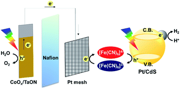 | ||
| Scheme 1 Z-scheme water splitting system using Pt/CdS as the H2-evolving system and the CoOx/TaON photoanode as the O2-evolving system. | ||
Results and discussion
Photocatalytic H2 evolution over Pt/CdS in the presence of different electron donors
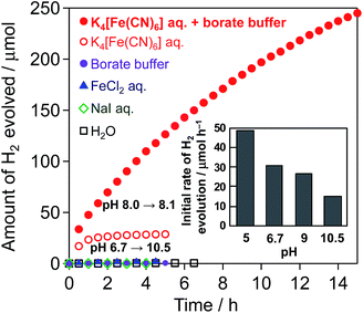
Fig. 1 shows the time course of H2 evolution from water over the Pt(1 wt%)/CdS photocatalyst in the presence of different electron donors ([Fe(CN)6]4−, I−, or Fe2+) under visible-light irradiation along with that in pure water without an electron donor. H2 evolution is observed only in the presence of [Fe(CN)6]4−, while H2 evolution terminates at ca. 28 μmol in the unbuffered aqueous solution (see the open red circles) accompanied by a significant increase in pH from 6.7 to 10.5. However, the production of nearly twice the amount (ca. 53.6 μmol) of oxidant, i.e., [Fe(CN)6]3−, was confirmed in the solution after the reaction by means of UV-Vis spectroscopy. This result indicates that photocatalytic H2 evolution over Pt/CdS proceeds under visible-light irradiation accompanied by the oxidation of [Fe(CN)6]4− to [Fe(CN)6]3− as follows:| 2H+ + 2e− → H2 | (1) |
| [Fe(CN)6]4− + h+ → [Fe(CN)6]3− | (2) |
It has been reported that the CBM and VBM of CdS are almost constant regardless of pH.14 Although the redox potential of [Fe(CN)6]3−/4− is independent of pH, that of water reduction shifts negatively with increasing pH in accordance with the Nernst equation. Therefore, the driving force for water reduction decreases with increasing pH (see Fig. S4†) via H+ consumption. As seen in the inset of Fig. 1, the rate of H2 evolution over Pt/CdS is indeed lower when the reaction is initiated in higher pH aqueous K4[Fe(CN)6] solutions (from 5 to 10.5, see Fig. S5† for the time course of H2 evolution). It can be therefore concluded that the significant decrease in the H2 evolution rate observed in Fig. 1 (open circles) can be explained by the significant increase in pH during the reaction by the consumption of H+ (eqn (1)). Another reason for the decreased rate will be the occurrence of a backward reaction on the Pt cocatalyst (i.e., the reduction of [Fe(CN)6]3−) instead of the reduction of H+ to H2.
Consequently, different buffers were tested to achieve stable H2 evolution by stabilizing the pH during the reaction. To avoid negative effects on the CdS photocatalyst and/or the [Fe(CN)6]3−/4− redox couple (e.g., dissolution or decomposition), mainly buffers that function under mild pH conditions (i.e., from 5 to 9) were tested. The use of BB at pH 8 effectively suppresses the decrease in H2 evolution, while the use of other buffers, such as citrate or phosphate buffers, unexpectedly results in much larger amounts of H2 being generated than that expected from the initial amount of [Fe(CN)6]4−. H2 is generated at a steady rate on Pt/CdS in the aqueous citrate buffer solution even without [Fe(CN)6]4−, indicating that the citrate buffer itself is oxidized. As for the phosphate buffers, the reason for the larger amount of H2 generated than that expected from the initial amount of [Fe(CN)6]4− has not yet been clarified. As seen in Fig. 1 indicated by closed red circles, H2 evolution over Pt/CdS proceeds at a relatively steady rate in the aqueous BB solution containing K4[Fe(CN)6], whereas no H2 evolution occurs in the BB solution alone. The amount of H2 generated reaches ca. 245 μmol at 15 h with a slight change in pH from 8 to 8.1. There is no significant change in the particle size (Fig. S6†), the XRD pattern (Fig. S7†), and the XPS spectra (Fig. S8†) of Pt/CdS after the reaction. However, the amount of [Fe(CN)6]3− generated in the BB solution after 15 h (ca. 380 μmol) is clearly smaller than the expected value (ca. 490 μmol) from the amount of H2 evolved. It is well known that light irradiation (both UV and visible) of aqueous [Fe(CN)6]3− induces ligand exchange (e.g., from CN− to OH−) resulting in the precipitation of Fe(OH)3.15 As shown in Fig. S9,† visible-light irradiation (λ > 400 nm) of a suspension of inactive SiO2 in aqueous K3[Fe(CN)6] solution for 15 h results in a ca. 20% decrease in the amount of [Fe(CN)6]3−, undoubtedly due to such photochemical reactions. Therefore, the slight difference in the stoichiometric amounts of H2 and [Fe(CN)6]3− may be attributed to the photochemical decomposition of the produced [Fe(CN)6]3−. Such a difference may be due to the competitive occurrence of photocorrosion on the CdS surface by photogenerated holes in the initial period, leading to the deposition of K2[CdFe(CN)6], as described later. These findings imply that a low concentration of the [Fe(CN)6]3− oxidant is necessary for steady-state Z-scheme water splitting.
The rate of H2 evolution gradually decreases with the progress of the reaction, even in the BB solution. This decrease is probably due to the occurrence of a backward reaction on the Pt cocatalyst (i.e., the reduction of [Fe(CN)6]3−) instead of the reduction of H+ to H2. Another reason may be light shielding by the [Fe(CN)6]3−, which has a photoabsorption peak around 420 nm. Nevertheless, we have demonstrated for the first time that a Pt/CdS photocatalyst can stably reduce water to H2 accompanied by an apparent generation of the oxidized species, i.e., [Fe(CN)6]3− from [Fe(CN)6]4−, when the pH of the solution is effectively buffered.
The Pt/CdS samples prepared from different commercial CdS particles (Aldrich) also show stoichiometric H2 evolution accompanied by the generation of [Fe(CN)6]3− (see the H2-evolution rates in Table 1). It should be noted that the procedure employed for Pt loading significantly affects the rate of H2 evolution in the presence of [Fe(CN)6]4−. The photodeposition of Pt in aqueous KOH solution affords the highest H2-evolution rate (67.7 μmol h−1), whereas other procedures result in much lower rates. This much higher rate of H2 generation indicates that the Pt loaded in KOH exhibits intrinsically higher catalytic activity for water reduction and/or lower activity for the re-reduction of the [Fe(CN)6]3− produced. The Pt/CdS sample prepared by photodeposition in aqueous KOH also exhibits a much higher rate of H2 evolution in the presence of sacrificial electron donors (S2− and SO32−), as seen in Table 1, and as previously reported by Wang et al.12 These findings indicate that Pt loaded in aqueous KOH has an intrinsically high activity for H2 evolution.
| Company | Crystal phase | Particle size of CdS/μm | Pt deposition method | Particle size of Pta/nm | Initial rate of H2 evolution/μmol h−1 | |
|---|---|---|---|---|---|---|
| [Fe(CN)6]4− | S2− and SO32− | |||||
| a Particle size of Pt was estimated using the TEM image (Fig. S3). | ||||||
| Alfa Aesar | Hexagonal | 2–5 | Photodeposition (1 M KOH) | 2–3 | 67.7 | 485 |
| Alfa Aesar | Hexagonal | 2–5 | Photodeposition (Na2S + K2SO3) | 2–4 | 5.0 | 51 |
| Alfa Aesar | Hexagonal | 2–5 | Impregnation (H2 reduction at 473 K) | 2 | 5.9 | 60 |
| Aldrich | Hexagonal + cubic | 0.2–0.3 | Photodeposition (1 M KOH) | 2 | 21.2 | — |
It can be concluded that Pt/CdS photocatalysts are able to photocatalytically generate H2 stably from aqueous solutions containing [Fe(CN)6]4− as an electron donor under visible-light irradiation, in contrast to the general understanding that CdS semiconductors suffer from photocorrosion in the absence of strong and sacrificial electron donors such as S2− or SO32−.
Rationalizing the stable H2 evolution from water over Pt/CdS in the presence of [Fe(CN)6]4−
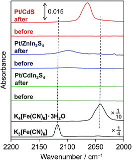
As shown in Fig. 2, a new IR absorption band emerges at ca. 2060 cm−1 for the Pt/CdS sample after reaction in the presence of [Fe(CN)6]4−. It is generally known that IR absorption in this range (ca. 2000–2200 cm−1) is derived from CN stretching in hexacyanometallates.16 However, the observed IR absorption band (at ca. 2060 cm−1) is clearly different from those of K4[Fe(CN)6]·3H2O (ca. 2040 cm−1) and its oxidant K3[Fe(CN)6] (ca. 2117 cm−1), suggesting that some new hexacyanometallates are formed during the reaction. A new IR absorption band at almost the same wavenumber has also been reported for a CdS photoanode irradiated in the presence of K4[Fe(CN)6].17 The authors suggested that this absorption was derived from CN stretching in a hexacyanometallate complex of Cd2+ and Fe2+ cations, i.e., [CdFe(CN)6]2−, which is a Prussian blue analogue.16a Reguera et al. have prepared various insoluble Kn−4[MFe(CN)6] complexes by the simple reaction of metal cations with K[Fe(CN)6]− and found that the IR absorption derived from CN stretching in Kn−4[MFe(CN)6] varies between 2025 and 2079 cm−1 depending on the M cation.16a The CN stretching in K2[CdFe(CN)6] is observed at 2067 cm−1,16a which is quite similar to that observed for the present Pt/CdS photocatalyst. These findings strongly suggest that an insoluble complex such as K2[CdFe(CN)6] is deposited on the surface of the Pt/CdS due to the spontaneous reaction between K4[Fe(CN)6] and the Cd2+ cations that are produced by the photocorrosion of CdS in the initial period of the photocatalytic reaction in BB solution. It was also confirmed that deposition of K2[CdFe(CN)6] occurs on the Pt/CdS surface after the photoreaction even in the absence of BB (see the ATR-FTIR spectra in Fig. S10†).The formation of an insoluble complex is also supported by the TEM images (Fig. 3) of the Pt/CdS sample after reaction. Some thin layers of ca. 2–5 nm thickness are observed after the reaction (b), while such layers are not observed in the sample before the reaction (a). Energy dispersive X-ray (EDX) analysis confirms the presence of Fe species, specifically near the surface, with Fe/S ratios ranging from 1.7 to 3.0. However, no appreciable presence of Fe species is observed for the Pt/CdS sample after stirring in aqueous K4[Fe(CN)6] solution.
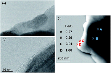 | ||
| Fig. 3 TEM images of Pt/CdS (a) before and (b) after reaction in BB solution (0.1 M, pH 8) containing 5 mM K4[Fe(CN)6]. (c) STEM image of Pt/CdS after reaction and its Fe/S ratio determined by EDX. | ||
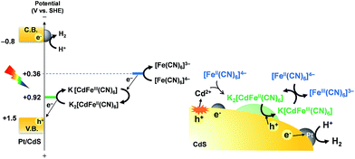
These results strongly suggest that the K2[CdFe(CN)6] layers formed on Pt/CdS effectively suppress further photocorrosion of CdS under light irradiation, thereby affording stable H2 evolution accompanied by almost stoichiometric generation of [Fe(CN)6]3−. The K2[CdFe(CN)6] species, which was prepared using the above-mentioned method, serves as a stable solid redox species (see Fig. S11†) with a standard potential of 0.92 V vs. the SHE, as previously reported.18 Considering the standard potential of [Fe(CN)6]3−/4−, as well as the VBM of CdS, it can be assumed that the oxidation of [Fe(CN)6]4− in the solution occurs via the redox cycle of the K2[CdFe(CN)6] species, as illustrated in Scheme 2.
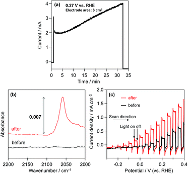
Consequently, in order to investigate the influence of the modification of the CdS surface with K2[CdFe(CN)6], we evaluated the photoelectrochemical properties of an n-type CdS electrode in aqueous BB solution (0.1 M, pH 8) containing K4[Fe(CN)6] (0.1 M) under visible light. Fig. 4a shows the time course of the photocurrent generated over the CdS photoanode at 0.27 V vs. the RHE. The photocurrent of the CdS electrode gradually increases during photoirradiation. The number of electrons (55.3 μmol) passing through the outer circuit within 30 min far exceeds the amount of CdS (1.4 μmol) loaded on the FTO. The ATR-IR spectra show that a new IR absorption band emerges at ca. 2060 cm−1 after chronoamperometric measurements (Fig. 4a), indicating the formation of K2[CdFe(CN)6] on the surface of the CdS photoanode, as shown in Fig. 4b. Fig. 4c shows the current–potential curves of the CdS electrode before and after reaction (Fig. 4a) in aqueous BB solution (0.1 M, pH 8) containing K4[Fe(CN)6] (0.1 M) under filtered visible light. The CdS electrode after the reaction (i.e., the K2[CdFe(CN)6]-loaded CdS electrode) exhibits a higher photocurrent density than the unmodified CdS electrode, especially at lower potentials. These results indicate that the hexacyanometallate K2[CdFe(CN)6] is spontaneously formed on the surface of the CdS electrode during photoirradiation and efficiently scavenges photogenerated holes and/or facilitates the oxidation of [Fe(CN)6]4− on the surface, consequently suppressing the deactivation of the CdS electrode. Such an effect was also suggested by Rubin et al. in 1986.17 Considering these findings, we can propose a reaction mechanism for stable H2 evolution from water over particulate Pt/CdS in aqueous K4[Fe(CN)6] solution as follows (see Scheme 2): some of the Pt/CdS surface is spontaneously covered with K2[CdFe(CN)6] in the initial period of the photocatalytic reaction. Subsequently, the formed K2[CdFe(CN)6] efficiently scavenges photogenerated holes in the Pt/CdS catalyst and effectively oxidizes [Fe(CN)6]4− to [Fe(CN)6]3−, resulting in stable H2 evolution. In other words, the K2[CdFe(CN)6] layers function as both a hole-transport agent and an effective surface modifier that prevents the photocorrosion of CdS during photocatalysis.
Photocatalytic H2 evolution over Pt/ZnIn2S4 and Pt/CdIn2S4 in the presence of [Fe(CN)6]4−
It may be expected that such K2[CdFe(CN)6] layers would also work for other metal sulfides, not only CdS, as an effective modifier to enhance the oxidation of [Fe(CN)6]4− and consequently inhibit photocorrosion. Consequently, ZnIn2S4 and CdIn2S4 were also subjected to photocatalytic H2 evolution in aqueous BB solution in the presence of [Fe(CN)6]4−. Both ZnIn2S4 and CdIn2S4 show activity for H2 evolution in the presence of sacrificial electron donors (S2− and SO32−, see Table 2) under visible light.10b,19 The Pt-loaded ZnIn2S4 sample shows appreciable H2 evolution (4.8 μmol h−1) from a BB solution containing [Fe(CN)6]4−, whereas Pt-loaded CdIn2S4 shows negligibly low activity for H2 evolution (0.8 μmol h−1), both of which are much lower than that of the Pt/CdS sample, as shown in Table 2.| Photocatalyst | Electron donor | Initial rate of H2 evolution/μmol h−1 |
|---|---|---|
| a Initial concentration of electron donor: 5 mM K4[Fe(CN)6] with BB (0.1 M, pH 8), 5 mM FeCl2 aq. (pH 2.4), 5 mM NaI aq. (pH 5.3), 0.35 M Na2S and 0.25 M K2SO3 (pH 13.7), catalyst mass: 50 mg, λ > 400 nm. | ||
| Pt/CdS | [Fe(CN)6]4− | 67.7 |
| Fe2+ | 1.1 | |
| I− | tr. | |
| S2− and SO32− | 338 | |
| Pt/ZnIn2S4 | [Fe(CN)6]4− | 4.8 |
| Fe2+ | tr. | |
| I− | tr. | |
| S2− and SO32− | 81.7 | |
| Pt/CdIn2S4 | [Fe(CN)6]4− | 0.8 |
| Fe2+ | tr. | |
| I− | tr. | |
| S2− and SO32− | 36.6 | |
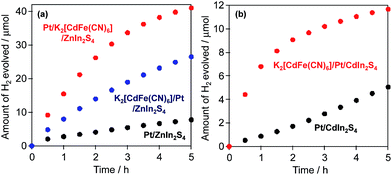
Fig. 2 shows the ATR-FTIR spectra of each sample before and after reaction in BB with [Fe(CN)6]4−. For the Pt/ZnIn2S4 sample, a small but obvious peak emerges at ca. 2099 cm−1 derived from hexacyanometallate CN stretching after the reaction, indicating the formation of a hexacyanometallate, namely Zn1.5[Fe(CN)6]·6H2O, on the surface of the Pt/ZnIn2S4.20 For the Pt/CdIn2S4 sample, no obvious new peaks are observed after the reaction. The significantly lower presence of hexacyanometallates for these mixed-metal sulfides implies that their rates of photocorrosion are significantly lower than that of the simple metal sulfide CdS. Consequently, we attempted to modify the surfaces of these mixed-metal sulfides with hexacyanometallates before the H2-generation reactions. The modification of Pt/ZnIn2S4 and Pt/CdIn2S4 with K2[CdFe(CN)6] was performed by impregnation with an aqueous solution containing K2[CdFe(CN)6] particles (10 wt% Cd), which were prepared by a precipitation method,16a followed by heating at 473 K for 30 min under Ar flow (denoted as K2[CdFe(CN)6]/Pt/sulfide). A Pt cocatalyst was also loaded onto the K2[CdFe(CN)6]-modified ZnIn2S4 particles by the photodeposition method (denoted as Pt/K2[CdFe(CN)6]/ZnIn2S4). Fig. 5 shows the time courses of H2 evolution over different ZnIn2S4 and CdIn2S4 samples in BB solutions containing K4[Fe(CN)6] under visible-light irradiation. Modification with K2[CdFe(CN)6] improves the H2-evolution rate in both cases, and almost stoichiometric amounts of [Fe(CN)6]3− are produced in all cases. It should be noted that the Pt/K2[CdFe(CN)6]/ZnIn2S4 sample exhibits a higher rate of H2 evolution than the K2[CdFe(CN)6]/Pt/ZnIn2S4 sample. This enhancement is probably due to the selective deposition of Pt on the ZnIn2S4 surface where K2[CdFe(CN)6] was not deposited using the sequential photodeposition method. Conversely, pre-loading with Pt undoubtedly results in random deposition of K2[CdFe(CN)6], even on the Pt particles loaded, lowering the effect of surface modification. These findings indicate that the modification of various metal sulfide photocatalysts with K2[CdFe(CN)6] is effective for improving their activity for H2 evolution in BB solutions containing [Fe(CN)6]4− as an electron donor under visible-light irradiation.
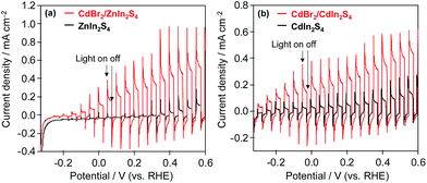
To confirm the function of K2[CdFe(CN)6] on the surface of these mixed-metal sulfides, photoelectrochemical measurements of n-type ZnIn2S4 and n-type CdIn2S4 electrodes were performed. For the surface modification of ZnIn2S4 and CdIn2S4 electrodes, an aqueous solution of CdBr2 (10 wt% Cd) was deposited onto the electrodes followed by heating at 473 K for 30 min under Ar flow. The resulting electrodes were immersed in BB solutions containing K4[Fe(CN)6], forming K2[CdFe(CN)6] layers on the electrode by the reaction of Cd2+ and K4[Fe(CN)6]. Fig. 6 shows the current–potential curves of the ZnIn2S4 and CdIn2S4 electrodes with and without CdBr2 loading in BB solutions containing [Fe(CN)6]4− under filtered visible-light irradiation. The photocurrents of CdBr2-loaded ZnIn2S4 and CdBr2-loaded CdIn2S4 electrodes are significantly higher than those of bare ZnIn2S4 and CdIn2S4 electrodes, indicating that the K2[CdFe(CN)6] formed on these electrodes scavenges photogenerated holes and/or facilitates the oxidation of [Fe(CN)6]4− on the surface.
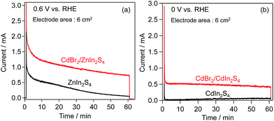
Chronoamperometry of these electrodes was also performed at fixed potentials (ZnIn2S4: 0.6 V, CdIn2S4: 0 V vs. the RHE) in BB solutions containing [Fe(CN)6]4− under visible-light irradiation. As shown in Fig. 7, CdBr2 modification also affords higher photocurrents in both cases. However, the photocurrent on the CdBr2-loaded ZnIn2S4 electrode gradually decreased with photoirradiation time, similar to that on the unloaded one, suggesting the occurrence of self-oxidative deactivation (e.g., photocorrosion). One possible reason for such deactivation on the CdBr2/ZnIn2S4 electrode would be that the K2[CdFe(CN)6] was nonuniformly deposited on the ZnIn2S4 surface, leaving a large part of the surface uncovered. The number of electrons (36.8 μmol for the ZnIn2S4; 16.7 μmol for the CdIn2S4) passing through the outer circuit within 60 min exceeds the amounts of K2[CdFe(CN)6] (2.8 μmol for the ZnIn2S4; 5.3 μmol for the CdIn2S4), respectively. These results indicate that K2[CdFe(CN)6] serves as an effective hole-transport agent for the oxidation of [Fe(CN)6]4−.
Z-scheme water splitting using metal-sulfide photocatalysts and CoOx/TaON photoanodes with a [Fe(CN)6]3−/4− redox mediator
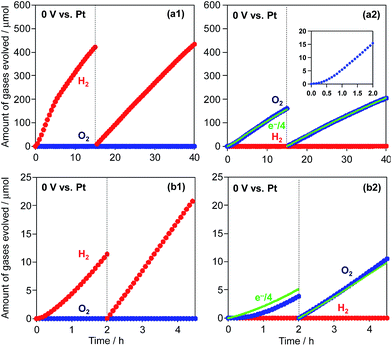
Finally, Z-scheme type water splitting into H2 and O2 was attempted by combining the metal-sulfide H2-evolving photocatalysts with appropriate O2-evolving systems. Although we have evaluated various particulate photocatalysts such as WO3 and TaON for O2 evolution in the presence of [Fe(CN)6]3− as the electron acceptor, no reliable O2 evolution was observed, probably due to the occurrence of the backward reaction (i.e., the re-reduction of [Fe(CN)6]4−). Therefore, in the present study we have employed a CoOx-loaded TaON photoanode,13 which was developed by our group and has been demonstrated to efficiently oxidize water to O2 even with relatively low applied potentials. Because the use of photoelectrochemical systems with two-compartment cells divided by cation-exchange membranes can effectively suppress such backward reactions, O2 evolution can proceed in one cell in the absence of [Fe(CN)6]3−. Before constructing our Z-scheme water-splitting system, O2 evolution over the CoOx/TaON electrode was evaluated in a two-compartment cell divided by a Nafion membrane, as shown in Fig. S12a.† BB solution (0.8 M, pH 8) was used as the supporting electrolyte, and K3[Fe(CN)6] (75 μmol) was dissolved in the BB solution at the Pt counter electrode side. A potential of 0 V was applied between the CoOx/TaON working and Pt counter electrodes. As shown in Fig. S12b,† the amount of evolved O2 increases with the progress of the reaction, and reaches the almost stoichiometric amount expected from the amount of [Fe(CN)6]3− in the initial solution. This result indicates that the CoOx/TaON photoanode can produce O2 even without an applied bias and with a relatively low concentration of [Fe(CN)6]3− at the counter electrode side. Subsequently, a Pt/CdS sample as a H2-evolving photocatalyst was suspended in the BB solution containing K4[Fe(CN)6] (5 mM) at the Pt counter electrode side. H2 and O2 are evolved simultaneously over Pt/CdS and the CoOx/TaON photoanode, respectively, under visible-light irradiation, as shown in Fig. 8a. The induction period for O2 evolution is undoubtedly due to the lack of the [Fe(CN)6]3− oxidant in the initial period. However, with the progress of H2 evolution on the Pt/CdS photocatalyst accompanied by [Fe(CN)6]3− accumulation, the photoelectrochemical O2 evolution starts on the CoOx/TaON photoanode. The gradual decrease in H2 evolution over 15 h is explained by the occurrence of the backward reaction (i.e., reduction of [Fe(CN)6]3−) instead of the reduction of H+ to H2. After 15 h, H2 and O2 are evolved at a steady rate and almost stoichiometric ratio (H2: 17 μmol h−1, O2: 8 μmol h−1) for 25 h. The concentration of the [Fe(CN)6]3− oxidant in the reaction solution is quite low (ca. 0.1 mM) after 15 h, leading to stable water splitting with an almost stoichiometric ratio. The amount of O2 evolved is in good agreement with a quarter of the electrons passing through the outer circuit (e−/4, indicated by the broken line). The total amount of H2 evolved over 40 h (850 μmol) is larger than the amounts of CdS (346 μmol) and [Fe(CN)6]4− (750 μmol) used for the reaction. The turnover number of reacted electrons to the molar amount of CdS was calculated to be 4.9. These results indicate that this reaction proceeds photocatalytically via a Z-scheme mechanism. Furthermore, the use of Pt/K2[CdFe(CN)6]/ZnIn2S4 as a H2-evolving photocatalyst also results in the stoichiometric evolution of H2 and O2 (H2: 8 μmol h−1, O2: 4 μmol h−1), as shown in Fig. 8b. These findings indicate the promise of the hexacyanometallate complex K2[CdFe(CN)6] as a modifier for metal-sulfide-based H2-evolving photocatalysts when coupled with an appropriate O2 evolution system and the [Fe(CN)6]3−/4− redox mediator for achieving efficient water splitting.Conclusions
In summary, we have revealed for the first time that surface modification with hexacyanometallate K2[CdFe(CN)6] is effective for stabilizing different metal sulfide photocatalysts, enabling them to generate H2 from water consistently in the presence of [Fe(CN)6]4−. K2[CdFe(CN)6] layers are spontaneously formed on the surface of CdS particles during the initial period of photoirradiation accompanied by photocorrosion, thereby endowing the Pt/CdS photocatalysts with high durability. Conversely, the formation of hexacyanometallate layers is not so efficient on mixed-metal sulfides such as ZnIn2S4 and CdIn2S4, probably due to their lower rates of photocorrosion. Thus, preloading of K2[CdFe(CN)6] on the sulfide surface is more effective for increasing the rate of H2 evolution. Although only the catalytic activity of K2[CdFe(CN)6] was clarified in the present study, the low but appreciable activity of ZnIn2S4 implies the catalytic activity of other hexacyanometallates, such as K2[ZnFe(CN)6]. Since a wide variety of metal sulfides exhibit both visible-light absorption and H2-evolving ability, including solid solution species in which band levels can be tuned more freely, this simple surface modification provides a new and promising strategy to achieve efficient water splitting under visible light using metal sulfide photocatalysts. In this work, Z-scheme water splitting under visible-light irradiation was demonstrated by using surface-modified metal sulfides with a CoOx/TaON photoanode as an O2-evolving system due to the lack of effective O2-evolving photocatalysts. However, the development of such photocatalysts will simplify the total system and probably increase its efficiency.Acknowledgements
This work was supported by the Core Research for Evolutional Science and Technology (CREST) of the Japan Science and Technology Agency (JST), and JSPS KAKENHI Grant Number 15K17896. The authors are also indebted to the technical division of the Institute for Catalysis, Hokkaido University for their help in building the experimental equipment.References
- (a) M. J. Esswein and D. G. Nocera, Chem. Rev., 2007, 107, 4022 CrossRef PubMed; (b) K. Maeda and K. Domen, J. Phys. Chem. C, 2007, 111, 7851 CrossRef CAS; (c) F. E. Osterloh, Chem. Mater., 2008, 20, 35 CrossRef CAS; (d) A. Kudo and Y. Miseki, Chem. Soc. Rev., 2009, 38, 253 RSC; (e) R. Abe, J. Photochem. Photobiol., C, 2010, 11, 179 CrossRef CAS.
- T. Kato, Y. Hakari, S. Ikeda, Q. X. Jia, A. Iwase and A. Kudo, J. Phys. Chem. Lett., 2015, 6, 1042 CrossRef CAS PubMed.
- (a) I. Tsuji, H. Kato and A. Kudo, Angew. Chem., Int. Ed., 2005, 44, 3565 CrossRef CAS PubMed; (b) I. Tsuji, H. Kato and A. Kudo, Chem. Mater., 2006, 18, 1969 CrossRef CAS.
- N. Buhler, K. Meier and J. F. Reber, J. Phys. Chem., 1984, 88, 3261 CrossRef.
- (a) J. R. Ran, J. Zhang, J. G. Yu and S. Z. Qiao, ChemSusChem, 2014, 7, 3426 CrossRef CAS PubMed; (b) N. Bao, L. Shen, T. Takata, K. Domen, A. Gupta, K. Yanagisawa and C. A. Grimes, J. Phys. Chem. C, 2007, 111, 17527 CrossRef CAS; (c) J. S. Jang, U. A. Joshi and J. S. Lee, J. Phys. Chem. C, 2007, 111, 13280 CrossRef CAS.
- (a) R. Abe, Bull. Chem. Soc. Jpn., 2011, 84, 1000 CrossRef CAS; (b) M. Higashi, R. Abe, K. Teramura, T. Takata, B. Ohtani and K. Domen, Chem. Phys. Lett., 2008, 452, 120 CrossRef CAS; (c) R. Abe, T. Takata, H. Sugihara and K. Domen, Chem. Commun., 2005, 3829 RSC; (d) H. Kato, M. Hori, R. Konta, Y. Shimodaira and A. Kudo, Chem. Lett., 2004, 33, 1348 CrossRef CAS; (e) Y. Sasaki, H. Kato and A. Kudo, J. Am. Chem. Soc., 2013, 135, 5441 CrossRef CAS PubMed.
- (a) K. Iwashina, A. Iwase, Y. H. Ng, R. Amal and A. Kudo, J. Am. Chem. Soc., 2015, 137, 604 CrossRef CAS PubMed; (b) A. Iwase, S. Yoshino, T. Takayama, Y. H. Ng, R. Amal and A. Kudo, J. Am. Chem. Soc., 2016, 138, 10260 CrossRef CAS PubMed.
- (a) W. Y. Wang, J. Chen, C. Li and W. M. Tian, Nat. Commun., 2014, 5, 4647 CAS; (b) Z. Li, W. Wang, C. Ding, Z. Wang, S. Liao and C. Li, Energy Environ. Sci., 2017, 10, 765 RSC.
- Y. Z. Fan, G. P. Chen, D. M. Li, F. Li, Y. H. Luo and Q. B. Meng, Mater. Res. Bull., 2011, 46, 2338 CrossRef CAS.
- (a) Z. X. Chen, Z. Y. Ren, J. J. Xu, Y. H. He and G. C. Xiao, Mater. Lett., 2014, 117, 17 CrossRef CAS; (b) B. Chai, T. Y. Peng, P. Zeng, X. H. Zhang and X. J. Liut, J. Phys. Chem. C, 2011, 115, 6149 CrossRef CAS.
- H. Kumagai, T. Minegishi, Y. Moriya, J. Kubota and K. Domen, J. Phys. Chem. C, 2014, 118, 16386 CAS.
- Y. B. Wang, Y. S. Wang and R. Xu, J. Phys. Chem. C, 2013, 117, 783 CAS.
- M. Higashi, K. Domen and R. Abe, J. Am. Chem. Soc., 2012, 134, 6968 CrossRef CAS PubMed.
- T. Watanabe, A. Fujishima, O. Tatsuoki and K. Honda, Bull. Chem. Soc. Jpn., 1976, 49, 8 CrossRef CAS.
- R. van Grieken, J. Aguado, M. J. Lopez-Munoz and J. Marugan, Appl. Catal., B, 2005, 55, 201 CrossRef CAS.
- (a) E. Reguera, A. Gomez, J. Balmaseda, G. Contreras and A. Escamilla, Struct. Chem., 2001, 12, 59 CrossRef CAS; (b) V. Jassal, U. Shanker, B. S. Kaith and S. Shankar, RSC Adv., 2015, 5, 26141 RSC.
- H. D. Rubin, D. J. Arent, B. D. Humphrey and A. B. Bocarsly, J. Electrochem. Soc., 1987, 134, 93 CrossRef CAS.
- C. H. Luangdilok, D. J. Arent, A. B. Bocarsly and R. Wood, Langmuir, 1992, 8, 650 CrossRef CAS.
- (a) M. A. Mahadadalkar, S. B. Kale, R. S. Kalubarme, A. P. Bhirud, J. D. Ambekar, S. W. Gosavi, M. V. Kulkarni, C. J. Park and B. B. Kale, RSC Adv., 2016, 6, 34724 RSC; (b) X. F. Bai and J. S. Li, Nanotechnology and Advanced Materials, 2012, 486, 181 CAS.
- C. W. Ng, J. Ding and L. M. Gan, J. Phys. D: Appl. Phys., 2001, 34, 1188 CrossRef CAS.
Footnote |
| † Electronic supplementary information (ESI) available. See DOI: 10.1039/c7se00151g |
| This journal is © The Royal Society of Chemistry 2017 |

