Graphene-based nanocomposites for energy storage and conversion in lithium batteries, supercapacitors and fuel cells
Nasir
Mahmood
,
Chenzhen
Zhang
,
Han
Yin
and
Yanglong
Hou
*
Department of Materials Science and Engineering, College of Engineering, Peking University, Beijing 100871, China. E-mail: hou@pku.edu.cn
First published on 19th September 2013
Abstract
Due to their unique properties, together with their ease of synthesis and functionalization, graphene-based materials have been showing great potential in energy storage and conversion. These hybrid structures display excellent material characteristics, including high carrier mobility, faster recombination rate and long-time stability. In this review, after a short introduction to graphene and its derivatives, we summarize the recent advances in the synthesis and applications of graphene and its derivatives in the fields of energy storage (lithium ion, lithium–air, lithium–sulphur batteries and supercapacitors) and conversion (oxygen reduction reaction for fuel cells). This article further highlights the working principles and problems hindering the practical applications of graphene-based materials in lithium batteries, supercapacitors and fuel cells. Future research trends towards new methodologies to the design and the synthesis of graphene-based nanocomposite with unique architectures for electrochemical energy storage and conversion are also proposed.
 Chenzhen Zhang | Chenzhen Zhang received his MS in Materials Science from Peking University in 2013. His research was focused on the liquid-phase synthesis and functionalization of graphene. |
Introduction
At present, provoking energy and environmental issues, such as the depletion of fossil fuels, pollution and global warming are ringing alarm bells to human society. Therefore, renewable energy storage and conversion materials, as well as their devices, are highly required.1 In this context, these problems can be overcome in two ways. Firstly, energy can be effectively converted from its infinite sources, such as the oxygen reduction reaction (ORR), solar power and water to applicable forms, such as electricity or fuel. To achieve this goal, fuel cells, solar cells and water splitting catalysts are of most concern.2–8 Secondly, environmental benignity, low cost, and high performance are required by energy storage devices. This is essentially because of the sporadic features of most renewable energy sources. Lithium-based batteries, especially lithium ion, lithium–air and lithium–sulphur, are the most useful and promising devices for such storage purposes.8–13 Another promising and efficient type of device for energy storage is the supercapacitor that can store and release energy in a few seconds.14 In such fields of catalysis and energy storage, the replacement of precious and rare metal electrodes and catalysts with commercially present substitutes has appealed for much consideration from both industrial and academic researchers. Although extensive studies have been carried out involving the use of non-precious metal electrodes and catalysts, the results are far from practical values owing to the limited performance of the discovered materials and environmental hazards. It is worth noting that both theoretical calculations and experimental values have demonstrated the considerable activity of low cost metal-free materials with unique electronic and nanostructural properties in a wide range of heterogeneous, electrochemical and catalytic processes. Among them, carbon and carbon-based materials have attracted much interest.15,16 Graphene is an atomically thin, planar membrane of carbon with exceptional properties, particularly electronic and electrochemical ones.17 Since the first report of its synthesis via a “Scotch tape” method in 2004, graphene research has emerged as one of the most active research fields of science.18 In the past few years, graphene has been extensively studied by chemists, physicists and material scientists and engineers.19 In graphene, the sp2 hybridization of carbon bonds is present, where the in-plane σc–c bonds are the strongest bonds and the out of plane π bonds, which result in a delocalized network of electrons, favour the electronic conduction of graphene and offer a weak interaction among graphene layers, or between graphene and a substrate.20–10 On the other hand, graphene can be synthesized and modified by facile solution methods that enable its easy utilization for various fields.21–23 Interestingly, the replacement of various different types of atoms (N, B, S and P) with carbon in graphene further enhanced the conductivity and electrochemical properties of graphene.17,24–26 Note that the synergistic effects of graphene composited with other nanomaterials like metals,27–29 metal oxides,30–33 sulphides,34–37 alloys38,39 and polymeric40 materials make it promising for energy storage and conversion devices.6,41Therefore, the use of graphene and graphene-based materials as low cost, environment friendly and high performance electrodes for ORR, supercapacitors and lithium-based batteries is highly favoured.18,24,42–50 In this feature article, we mainly focus on the synthesis and unique electrochemical properties of graphene and its application towards lithium-based different types of batteries, supercapacitors and ORR for fuel cells.
Structure of graphene
Graphene is a two dimensional single layer of sp2 hybridized carbon atoms with hexagonal structure. The electronic properties of graphene are based on the arrangement and number of graphene layers. Few-layer graphene possesses an electronic structure different from that of bulk graphite. At such thicknesses, the layer number and interlayer ordering could affect the physical and chemical properties of graphene (Fig. 1a and b). For instance, mono-layer graphene is a zero-gap semiconductor with linear energy dispersion and its charge carriers can be considered as a function of massless materials, which travel at an effective speed of ∼106 ms−1.51 This unique band structure of single layer graphene has made graphene a fascinating system for quantum electrodynamics. Bi-layer graphene electrons obey parabolic energy dispersion and the material behaves like a zero-gap semiconductor. However, the tuneable band gap of bi-layer graphene can be modified by breaking the symmetry between the two layers.52 These results propose that bi-layer graphene could be a novel material for future optoelectronic and microprocessor applications. In contrast, tri-layer graphene performs as a semi-metal and its band overlapping can be controlled by applying an external electric field.53 The above properties of multilayer graphene can hold only with the Bernal ABAB stacking of natural graphite. Changes in the stacking arrangement via lateral translation or angular mis-orientation can affect the interlayer interactions and their properties (Fig. 1b).54 Theoretical works have proven that the band gap of graphene nanoribbons (GNR) fluctuates inversely with the width of ribbon and edge type (e.g., zigzag vs. armchair).55 The production of GNR by physical methods produces defects which, along with other lithographical issues, can hinder their device performances (Fig. 1c).53,56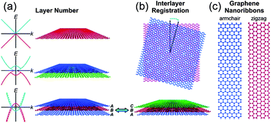 | ||
| Fig. 1 Polydispersity map of graphene. The electronic and optical properties of graphene depend on (a) the layer number and (b) the interlayer registration. Schematic band diagrams in the left of panel (a) show the graphene band structure with (solid curves) and without (dashed curves) an applied gate bias. (c) Graphene nanoribbons have band gaps that vary as a function of their width and edge type. Copyrights reserved to the American Chemical Society.51 | ||
Synthesis of graphene
Graphene and its composite are an emerging field that has received tremendous attention from scientists and various methods of its synthesis have been explored, including mechanical fabrication,57 physical58–60 and chemical synthesis.61–67 Among these methods, chemical vapour deposition (CVD)68 and the exfoliated synthesis of graphene from graphite69,70 have become the most promising for the large-scale synthesis of graphene. Zhang et al.71 reported the vapour trapping growth of flower like graphene via a CVD method. Fig. 2a shows a schematic illustration of the experimental setup that is used to prepare the six and four lobed flowers of graphene, in which graphene was prepared using CH4 as the carbon source on copper foils. H2 was introduced to the system at 7 sccm min−1 under a pressure of 40 mTorr and the temperature was raised up to 1000 °C in 40 min. The Cu foils were first annealed at 1000 °C for 20 min. Then, CH4 (1 sccm min−1) and H2 (12.5 sccm min−1) were introduced to the reaction system for the growth of graphene and the pressure was maintained at 200 mTorr for 30 min and finally it was allowed to cool down the CVD chamber to room temperature. Fig. 2b shows a scanning electron microscope (SEM) image of graphene grown by the CVD method described above. The SEM image clearly points out that CVD is a very sophisticated method to grow highly pure and controlled number of layers of graphene sheets with a low O/C ratio that is necessary for a better performance of graphene.72–74 However, the problems of harsh conditions, high expense and limitation to large scale production are the main hindrances that are forcing scientists to develop chemical methods that can be controlled easily and produce large amounts of graphene for practical applications.25,75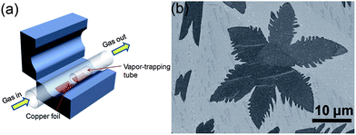 | ||
| Fig. 2 (a) Schematic diagram of a vapour trapping CVD method for graphene growth. (b) SEM images of a six-lobe graphene flower grown on Cu foil inside the vapour trapping tube. Copyrights reserved to the American Chemical Society.71 | ||
An alternative synthetic method, that is usually utilised because of its ease of production, low cost and high yield, is the chemical exfoliation of graphite. This includes the use of sonication in both the dissolution and intercalation stages.76 For example, with the assistance of sodium chelates77 which encapsulate the layers of graphene from both sides, graphite flakes are dispersed in a water–surfactant solution and converted into monolayer graphene sheets by the shearing force of sonication.78 However, it is also possible without the addition of any additive in many organic solvents that have an affinity for graphite where sonication is used to provide the energy to split the graphene precursor.65,79–81 The successful exfoliation by sonication depends on the appropriate choice of solvent and surfactant, as well as sonication parameters, such as sonication frequency, amplitude and time.80,82
The solvothermal exfoliation of graphite is commonly used to produce large amounts of graphene. Qian et al.21 reported the exfoliation of graphite with the help of highly polar organic solvent acetonitrile at 180 °C for 12 h. Acetonitrile is a bipolar organic solvent that inters into the graphite and peels off mono- or bi-layers of graphene under high pressure. Fig. 3 explains the synthesis of graphene from expendable graphite (EG) via solvothermal exfoliation in acetonitrile with a high yield of up to 10–12%.
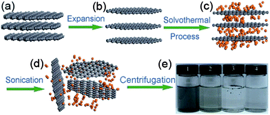 | ||
| Fig. 3 Schematic illustration of the solvothermal assisted exfoliation and dispersion of graphene sheets in acetonitrile (ACN): (a) pristine expandable graphite; (b) EG; (c) insertion of ACN molecules into the interlayers of EG; (d) exfoliated graphene sheets dispersed in ACN; (e) optical images of four samples obtained under the different conditions. Copyrights reserved to Springer.21 | ||
Doped graphene materials have attracted tremendous attention because of their enhanced physical and chemical performance, and how dopant elements enhance these properties are discussed further in the respective sections. For example, Zheng et al. reported the synthesis of B, N-doped graphene from solvothermal exfoliated graphene oxide (GO) via a two-step doping strategy: N was first introduced by annealing with NH3 at a moderate temperature of 500 °C, and then boron was incorporated by pyrolysis of the as-synthesized nitrogen (N)-doped graphene with H3BO3 at a high temperature of 900 °C.25 Other examples include the doping of sulphur to graphene via the annealing of graphite oxide in the presence of benzyl disulphide in an atmosphere of protective argon gas.24 Highly air-stable phosphorous (P)-doped graphene was prepared by a CVD method using triphenylphosphine (TPP) as a phosphorus source.83 Another example of boron doping in graphene sheets was carried out through a CVD approach using boron powder and ethanol as the boron and carbon precursors, respectively.84 However, among all the doped graphene materials, N-doped graphene has received tremendous attention from researchers. For the synthesis of N-doped graphene, a lot of methods were explored, including CVD, but their practical applications are limited due to harsh experimental conditions, like high temperature and low yield.26 To overcome these challenges, Qian et al. developed a two-step liquid phase process to synthesize N-doped graphene, as presented in Fig. 4. In the first step, graphene was synthesized by a solvothermal exfoliation process in acetonitrile using expandable graphite (EG) as the starting precursor. After repeated centrifugation at 500 and 1500 rpm, few layer graphene was collected and then dispersed in acetonitrile for further supercritical reaction to dope nitrogen to the graphitic plane of graphene.85 Further research was carried out to simplify the synthetic process of N-doped graphene in the liquid phase. For the solvothermal reduction of GO, its colloidal dispersion with N2H4 and aqueous NH3 at pH of 10 was carried out.33 However, the nitrogen content of the as-synthesized nitrogen-doped graphene was 4–5 wt% less than the oxygen content of 8 wt%. A well-controlled liquid phase synthesis process for N-doped graphene with low oxygen content still needs to be designed.
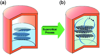 | ||
| Fig. 4 Schematic illustration of N-doped graphene sheets prepared via SC reaction with ACN at 310 °C: (a) few-layer graphene sheets were obtained by a solvothermal assisted exfoliation process and centrifugation, and then were mixed with ACN in a corundum-lined autoclave (b) N-doped graphene sheets were formed after SC reaction with ACN at 310 °C for the designated time. Copyrights reserved to the American Chemical Society.85 | ||
Recently, Zhang et al. developed a facile one-step solvothermal method to synthesize N-doped graphene from GO in the presence of aqueous ammonia.23 The X-ray photoelectron spectroscopy (XPS) results presented in Fig. 5 confirm the successful doping of nitrogen with higher contents up to 10.5 at.%. The schematic diagram presented in Fig. 5d and the XPS results also reveal that the oxygen contents in the as-synthesized N-doped graphene is lower. Furthermore, the N 1s XPS spectra shows the presence of five typical nitrogen states, including pyridinic N (ca. 398.3 eV), pyrrolic N (ca. 400.1 eV), graphitic N (ca. 401.4 eV), oxidized N (402–404 eV) and amino N (ca. 399.2 eV). Probably, this strategy is helpful for the synthesis of N-doped graphene in a very simple way with better yields and low oxygen content.
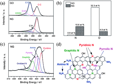 | ||
| Fig. 5 XPS spectra of nitrogen-doped graphene: (a) C 1s XPS spectra of GO and nitrogen-doped graphene; (b) percentages of nitrogen and oxygen in the GO and nitrogen-doped graphene; (c) N 1s XPS spectrum of nitrogen-doped graphene; (d) schematic of the nitrogen-doped graphene. Copyrights reserved to Elsevier Ltd.23 | ||
Potential applications of graphene
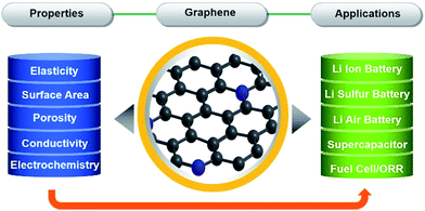
Graphene due to its exceptional properties, such as its two dimensional structures that can be assembled into three dimensional networks, large specific area and porosity, strong mechanical strength, high conductivity and electrochemically active nature, has become a main focus of research. Graphene can be synthesised in numerous ways based on physical and chemical methods, and composited with a variety of materials that make graphene fit for many applications. Graphene-based materials have tremendous potential for application in various fields, like electronics, catalysis, energy storage and conversion.1,20,75,86–91 The properties of graphene which make it useful in various applications are described in Scheme 1. Scheme 1 gives a clear picture of how the properties of graphene make it useful in different kinds of applications. Although, graphene is utilized to enhance the electrochemical activity of a variety of materials. In the following part of this feature article we will describe the applications of graphene and graphene-based materials in the fields of lithium ion battery (LIB), lithium–air/oxygen battery, lithium–sulphur battery, supercapacitors and ORR.Lithium ion batteries
The LIB was first introduced in 1991 and has become the major source of power for portable electronic devices, especially laptop computers and wireless telephones in the last 20 years. Current LIB technology is based on LiCoO2 and graphite electrodes, which is known as the first generation of LIBs.92 In the future, electric vehicles (EV) and hybrid electric vehicles (HEV) may be the best possible solution to reduce emissions of greenhouse gases and critical pollutants by replacing petroleum-based transport. Rechargeable LIBs with high specific energy and energy density with respect to other cell chemistries are well suited for these kinds of vehicles. For example, currently, practical nickel-metal hydride (NiMH) batteries dominate in the HEV market with nominal specific energy and an energy density of 75 W h kg−1 and 240 W h L−1, respectively. In contrast, LIBs can achieve double the specific energy (150 W h kg−1) and energy density (400 W h L−1) of NiMH.93 For the advancement of LIBs, numerous concepts, principally innovative novel positive and negative electrode materials, need to be developed.Anodes for lithium ion batteries
Recent advancements in communication and electronics devices need batteries with faster recharging, longer life and lower cost. Fortunately, LIBs are one of the big achievements in advanced material electrochemistry,94 possessing larger energy and power densities than all other rechargeable batteries, which could fulfil the necessities of energy storage devices with a comparatively long cycle life.95 Continuous progress is going on in the field of LIBs. In particular, anode materials composed of lithium metal and alloys were cast off in 1980s, which were later substituted by carbon materials to keep the LIBs safer.96 Graphite remained the dominant commercial anode material for a long time, but because of the low theoretical capacity (372 mA h g−1) of graphite, it is not suitable as a practical anode for hybrid EVs and HEVs.36 In this perspective, other anode materials were explored, such as silicon (4200 mA h g−1),97 tin (994 mA h g−1)36 and germanium (1600 mA h g−1).98 However, the critical shortcomings of these materials are low capacity, poor rate capability and rapid capacity fading because of their volume expansion and low conductivity. To solve these drawbacks, research on the designing of composites composed of carbon,27 graphene99 and other metals28 were extensively carried out. However, to achieve the practical values that make LIBs applicable for EVs and HEVs, an appropriate electrode material is still a challenge. On the other side, because of its conductive, electrochemical active and elastic nature,41 graphene has been proven to overcome issues, such as volume expansion, low conductivity, rate capability and the capacity fading of electrode materials.100,101 So far, both theoretical and experimental results have proven that the doping of N, B or S atoms into graphene planes could further increase its electrochemical performance and electron transport ability.17,26,102Nowadays, researchers focus on the fabrication of anode materials comprising of graphene, doped graphene and graphene-based composites of electrochemically active materials. Wang et al.103 reported the in situ constructing strategy in which a highly conductive network, hierarchically porous structure and heteroatom doping are ideally combined in one graphene electrode. This kind of strategy offers a number of advantages, like the porous structure which can accommodate more lithium ions,35 hierarchical designing which can overcome the problem of aggregation and the large interfacial resistance of loosely stacked graphene sheets.30 On the other hand, the doping of heteroatoms could improve the ability of graphene to intercalate more lithium ions, enhance the conductivity of graphene and facilitate the transport of electrons and ions.26,27Fig. 6a & b show the growth of the above mentioned doped hierarchically porous graphene (DHPG). It is apparent that the presented morphology could be effective for a better performance as an anode in LIBs. The performance of DHPG as an anode electrode is presented in Fig. 6. Cyclic voltammetry (CV) curves confirm the multi-position storage of lithium ions in the DHPG electrode, as shown in Fig. 6c. Fig. 6d also shows that the DHPG-based electrode has a high performance, even at a faster charging rate with improved coulombic efficiency.
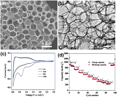 | ||
| Fig. 6 TEM images of DHPG (a&b). The electrochemical performance of DHPG electrodes: (c) cyclic voltammograms at a scan rate of 0.1 mV s−1 and (d) capacity over cycling at different current densities. Copyrights reserved to the American Chemical Society.103 | ||
Metal sulphides are promising materials as anodes for LIBs due to their high theoretical capacities, low cost and ease of availability. However, capacity fading, low conductivity and poor cyclability are the major drawbacks of cobalt sulphides,104–106 which are associated with the volume expansion of electrodes that results in the decay of specific capacity and the formation of polysulfide anions. These polysulfide anions by dissolving in the organic solvent of electrolyte cause low conductivity. Also migration of the polysulfide anions across the separator membranes towards the cathode leads to the poor rate capability. Mahmood et al. used graphene to resolve these issues,35 it acts as a conducting matrix, as well as a buffering substrate. Apart from the enhancing effect on the electrical conductivity, graphene with a large surface area and high flexibility protects the active material from structural changes and improves the contact between the electrolyte and active material.30 Graphene can also hinder the dissolution of polysulfide anions in the electrolyte by absorbing them on its amorphous surface, as a result improving the cyclic life by enhancing the conduction of ions. Fig. 7 shows the TEM image and cyclic performance of the Co3S4/G composite, which confirms the synergetic effect of graphene and Co3S4 for improved performance.
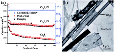 | ||
| Fig. 7 (a) The cyclic behaviour of Co3S4 and Co3S4/G composites with the columbic efficiency at a 0.2 C rate between 0 and 3 V vs. Li+/Li. (b) A TEM image of the Co3S4/G composites. Copyrights reserved to Wiley.35 | ||
Graphene is preferably used for the encapsulation of electrochemically active materials for energy storage and conversion because of its extraordinary conductivity, large surface area, excellent flexibility and high chemical stability.30,107 Graphene can be functionalized by various simple methods to produce localized highly reactive regions which result in impressive properties for respective applications.1,87,90 Silicon is considered as a most promising anode material for next generation LIBs, but its structural and interfacial stability issues still remain a big challenge. One way to resolve these problems is to build energetic silicon architectures supported with elastic and conductive materials that could be adaptable. Wang et al.108 developed a novel self-supporting binder free silicon-based electrode through the encapsulation of silicon nanowires with dual adaptable apparels (overlapped graphene sheaths and reduced GO overcoats). The resulting architecture gives two advantages to the electrode. Firstly, sealed and adaptable coated graphene sheets avoid the direct contact of encapsulated silicon and electrolyte, enabling the structural and interfacial stabilization. Secondly, the flexible and conductive reduced GO controls the pulverization of the electrode and provides the conductive homogeneity to the composite. As a result, the composite electrodes exhibit an excellent reversible specific capacity and rate capability with high capacity retention. It is generally accepted that the creation of defects in the graphitic planes of graphene by replacing the carbon atom with heteroatoms increases its electrochemical performance.26 For this purpose, Zhou et al.33 used N-doped graphene as a conductive and elastic support to pin SnO2 nanoparticles (NPs). This combination is one step towards realizing tin-based anodes for LIBs. The resulting composite has a high reversible capacity and good cycle life because the NPs are pinned on the graphene sheets by Sn–N–C bonds that prevent the aggregation of NPs. Meanwhile, graphene maintained the undisturbed supply of the electrons that enhanced the conductivity and stabilized the reversible storage process of lithium ions.45,109
Very recently, Mahmood et al.110 used N-doped graphene to anchor the NPs of Ni3S4 and explored its effect on the performance of Ni3S4. The synthetic scheme used is presented in Fig. 8, which illustrates that the NPs are anchored by the functional groups present on the graphene sheets. Here, they explored that annealing increased the electrochemical coupling between NPs and graphene, which enhanced the electrochemical performance of the composite. Also another interesting phenomenon reported was that by annealing, one phase of nickel sulphide (Ni3S4) is converted to another phase (NiS1.03), as shown in Fig. 9a.111Fig. 9 confirms that the high reversible capacity with excellent capacity retention is the result of the synergetic effect of graphene and NPs. In this work, they explored three factors that have a capacity enhancing effect, firstly the annealing process boosts up the electrochemical performance of the composite by making better electrochemical coupling. Secondly the oxygenated groups present on the graphene sheets are used to pin the NPs, so the effect of the oxygenated groups on the conductivity and electrochemical performance is eliminated and a controlled thickness layer of solid electrolyte interface (SEI) film is formed.28 The third factor which promotes the reversible capacity of the composite is the type of nitrogen in the graphitic planes of graphene, as pyridinic graphene is more electrochemically active than pyrrolic graphene (Fig. 9).26 The synergetic effect of the composite is also depicted in the CV curves (the peak in the oxidation process near 1.2–1.4 V is related to the composite) presented in Fig. 9d. The last and most important benefit of graphene incorporation is the retention of structural integrity limiting the production of polysulphide anion.
 | ||
| Fig. 8 Schematic illustration of the preparation of the Ni3S4/NG composite. Copyrights reserved to Wiley.110 | ||
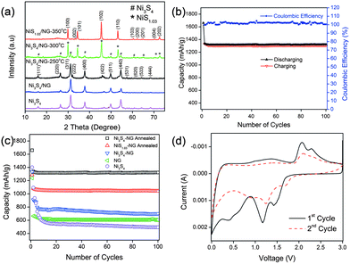 | ||
| Fig. 9 (a) XRD patterns of Ni3S4, Ni3S4/NG, Ni3S4/NG-250 °C, Ni3S4/NG-300 °C and NiS1.03/NG-350 °C. (b) Cyclic behaviour and coulombic efficiency of the Ni3S4/NG-250 °C composite at 0.2 C in the range of 0–3 V. (c) Comparison of the discharge capacities of Ni3S4, NG, Ni3S4/NG, Ni3S4/NG-250 °C and NiS1.03/NG-350 °C at 0.2 C in the range of 0–3 V. (d) CV curves of Ni3S4/NG-250 °C at a scanning rate of 0.2 mV s−1 in the range of 0–3 V vs. Li+/Li. Copyrights reserved to Wiley.110 | ||
Electrochemical impedance spectroscopy (EIS) measurements are well known to study the conductivity influence of graphene in the composite. Fig. 10a shows the Nyquist plots of nickel sulphide and graphene composites. The inset of Fig. 10a represents the equivalent circuit diagram which was used to calculate the actual values of the different resistances. Fig. 10b shows a schematic illustration of the composites on the basis of the electrochemical behaviour towards the reversible storage of lithium ions. From Fig. 10b, it is obvious that both NPs and N-doped graphene are active towards the reversible storage of lithium ion and the enhanced performance of the composite is because of the synergetic effect between NPs and N-doped graphene. From Fig. 10a it is clear that the introduction of graphene reduces the different types of resistances, like electrolytes, charge transfer, SEI film resistances and facilitates the easy and faster transfer of electrons and ions. These are the resistances which are overcome by graphene to enhance the performance of the composites. Similar behaviour is presented in various systems that use graphene as a conductive, elastic and electrochemically active substrate.27,30,31,35,108,110
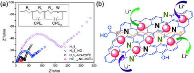 | ||
| Fig. 10 (a) Nyquist plots for Ni3S4, Ni3S4/NG, Ni3S4/NG-250 °C and NiS1.03/NG-350 °C in the range of 100 kHz to 10 mHz. (b) Schematic illustration of the active nature of both nickel sulphides NPs and nitrogen-doped graphene and the conduction enhancement effect of NG. Copyrights reserved to Wiley.110 | ||
Cathodes for lithium ion batteries
Rechargeable LIBs have been declared as one of the most promising energy storage devices, especially as power sources for EVs and HEVs. Apart from high energy density, high power density is another essential requirement in the aforementioned applications. Cathode materials in conventional LIBs are based on lithium transition metal phosphates or oxides (e.g. LiFePO4 or LiCoO2)112,113 that can reversibly store lithium ions. With the advances in research, many inorganic cathode materials have been established to display high capacity retention at reasonable charge–discharge rates, such as 1 C or 5 C, but failed to release all of their energy in a few seconds like supercapacitors, ultimately leading to low capacities under high charge–discharge conditions. This can be attributed to the relatively slow lithium ion diffusion kinetics in the electrode. Here, we will give an insight into the different modifications based on graphene and active materials to enhance the performance and power density of LIBs. Wang et al.114 reported the role of oxygen groups for the better performance of graphene paper as a cathode for primary LIB. It was also investigated that by annealing oxygen free graphene paper can be achieved, but it was good to use deoxygenated paper as the anode. Another problem associated with oxygenated graphene is that it produces a thick SEI,27 which results in the loss of large capacity as it hinders the passage of lithium ion diffusion.34,35,115 This phenomenon was also presented in the results of Wang et al. Rao et al.116 reported a lithium transition metal oxide (LiNi1/3Co1/3Mn1/3O2) as a cathode for second generation of LIBs, but faced capacity fading as well. Thus, to solve this problem, they incorporated graphene to the system and observed the high capacity retention at even faster charge–discharge rates. To demonstrate how graphene enhanced the performance and maintained the high capacity retention, they used EIS, which confirmed that graphene can reduce the SEI film resistance to achieve a faster movement of lithium ions across the electrode and allow better contact between the active materials and electrolyte.27,28Liu et al.117 developed a facile strategy to synthesize iron fluoride NPs pinned on graphene sheets by producing defects in graphene sheets by HF, these defects were the anchoring sites for NPs and because of these defects, the composites showed a better performance. Fig. 11 shows the synthetic scheme of the FeF3–graphene composite. Fig. 12 presents the electrochemical performance of the composite and it is clear that the composite has a good performance and capacity retention, even at faster charge–discharge rates. The group claimed that the higher performance was attributed to the intimate contact of NPs with 2D graphene sheets and the presence of conductive substrate in the form of graphene. The strong interactions in NPs and graphene through covalent or van der Waals binding can protect their aggregation during the reversible lithium intercalation and as a result are helpful for a higher performance.33 Another group also used N-doped graphene as a conductive and electrochemical active buffering substrate to improve the capacity and capacity retention of VO2 by preserving the structural changes and synergism between graphene and VO2 providing a large contact area for the electrolyte and electrode.118 It is also a useful method to improve the conductivity and electrochemical properties of graphene by incorporating heteroatoms in the graphitic plane of graphene.24,26,33,34 Therefore the overall performance of the electrode is increased.
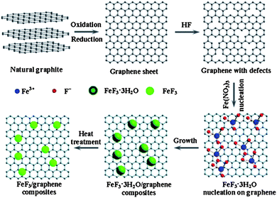 | ||
| Fig. 11 Diagram of the chemical route to the iron fluoride–graphene nanocomposites for LIB cathode materials. The iron fluoride NPs are not shown at their actual size. Copyright reserved to the Royal Society of Chemistry.117 | ||
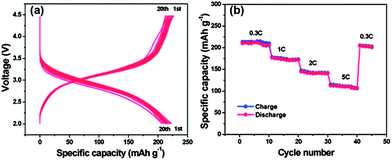 | ||
| Fig. 12 Electrochemical performances of the FeF3–graphene nanocomposite cathode materials measured in the voltage range of 2.0–4.5 V: (a) voltage–capacity curves at a 0.2 C rate in the first 20 discharge–charge cycles; (b) cycling performance at different rates (increased from 0.3 C to 5 C). Copyrights reserved to the Royal Society of Chemistry.117 | ||
Other than common inorganic materials, organic cathode materials, consisting of small molecules and polymers, have also been highlighted recently as a novel group of green lithium battery electrodes, owing to their sustainability and environmental benignity.119 Song et al.120 reported the graphene–polymer (poly-(anthraquinonyl sulphide) and polyimide) hybrid cathode for LIBs. The resultant hybrid has a number of advantages, such as high performance even at higher charge–discharge with extraordinary capacity retention. The hybrid composite is environmentally friendly and safe to use in high charge–discharge applications. Thus the proper combination of suitable high energy density materials with conductive substrates, both for anodes and cathodes will enable the commercial availability of second generation LIBs for EVs and HEVs.
Lithium–air batteries
To address the problems concerned with the climate change of the world and the electrification of transport, development in energy storage devices are required.121,95 Among several storage systems, rechargeable batteries, particularly LIBs are a smart technology because of their high energy density and excellent efficiency. LIBs have been extensively used in a variety of electronic devices that are important in life.122 However, after a steady improvement up to 15% during the last two decades, the energy density of LIBs is now reaching its theoretical limit defined by the specific energies of cathode and anode materials used in LIBs and can provide an energy storage limit up to 100 miles.123 However, in the recent decades of research, the pursuit of the next generation of energy storage devices has been investigated worldwide. Among various electrochemical energy storage systems investigated until the present time, the lithium–air (Li–air) battery is one of the most promising breakthroughs of electrochemistry.124 Li–air batteries have advantages over conventional LIBs with a 10 times higher theoretical energy density because lithium metal as an anode has a capacity 10 times higher than that of conventional graphite anodes.125 Secondly, oxygen as the cathode of a Li–air battery can be absorbed easily from the environment resulting in a substantial reduction of the weight and cost of the battery. In this context Li–air batteries can achieve sufficient amounts of energy storage for EVs that can derive the EVs up to 300 miles.126Fig. 13 shows a schematic of the generally operated Li–air batteries, of the two basic types of Li–air batteries, one is non-aqueous and the other one is an aqueous battery based on electrolytes.9,127 The basic chemical reaction at the anode is similar in both cases, as illustrated in eqn (1), but the fundamental reaction at the cathode is different and is based on the medium as represented in eqn (2) and (3) (aqueous) and (4) (non-aqueous).126,128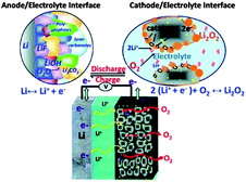 | ||
| Fig. 13 Schematic representation of an Li–air battery. Copyrights reserved to the American Chemical Society.9 | ||
Anode
| Li ↔ Li+ + e− | (1) |
Cathode (aqueous)
| alkaline: O2 + 2H2O + 4e− ↔ 4OH− (Eo = 3.43 V vs. Li/Li+) | (2) |
| acidic: O2 + 4e− + 4H+ ↔ 2H2O (Eo = 4.26 V vs. Li/Li+) | (3) |
Cathode (non-aqueous)
| O2 + 2e− + 2Li+ ↔ Li2O2 (Eo = 2.96 V vs. Li/Li+) | (4) |
There are a number of factors that could affect the performance of Li–air batteries, such as oxygen partial pressure, relative humidity, electrolyte composition, selection of catalysts, the structure of the carbonaceous materials, air electrode and the overall cell design.123,129–131 Another main problem is the precipitation of reaction products, such as Li2O2, on the surface and the pores of the electrode which ultimately block the oxygen passage and decrease the capacity of the Li–air batteries.132 Thus, there is an acute need to construct a novel air electrode that has the ability for a rapid oxygen diffusion pathway and catalyse LiO2 reactions preventing excessive growth of the discharge products that block chemical pathways through its micropores and nanoporosity (<50 nm), respectively.125,128
Considering the above points in synthesis, there are three basic issues that have so far hindered the complete development of the Li–air battery. First the instability of the electrolytes in the cell environment. This problem can be solved by searching media expected to be more stable than common carbonate organic electrolytes, such as dimethoxy ethane-based solutions, ionic liquid-based solutions and poly(ethyleneoxide)–lithium salt, for example, PEO–LiCF3SO3 polymer membranes, however, with limited achievement.11,127 The second problem is associated with the limited reversibility of the electrochemical process, which can be addressed by developing appropriate cathode architectures and also by exploration of the catalyst.9,130 The third point is the reactivity of the lithium metal anode which is hard to resolve, but efforts have been carried out by using some coating that can prevent the dendrite formation on the surface of the metallic lithium anode.127,133
Cathodic catalysts for lithium–air batteries
The performance of the Li–air batteries depends on the air electrode and this determines the voltage drop of the Li–air battery. The performance is affected by the type, structure and morphology of the materials. In the early classes of Li–air batteries porous carbon was used as the air electrode and all the Li–O2 reactions occurred on the carbon. So it is important to get highly porous carbon with a large surface area for the better performance of the battery. Likewise, super P-carbon has a smaller surface area of 62 m2 g−1, but it has a higher performance than normal carbon because it has a higher porosity with an average pore size of 50 nm. Therefore it is obvious that the pore size is more important than the surface for better catalysis and a smooth pathway for the air to pass. Currently, graphene and graphene-based catalysis are also in use as air electrodes and result in very high performances. Xiao et al. synthesized functionalized graphene sheets (FGSs) that self-assembled hierarchically into three dimensional (3D) porous networks (Fig. 14a). These FGSs were used as the air electrode in Li–air batteries that delivered an extremely high capacity of 15![[thin space (1/6-em)]](https://www.rsc.org/images/entities/char_2009.gif) 000 mA h g−1 (Fig. 14c), because of their ability to accommodate the by-products of catalysis and enhance the pathway of air, emphasizing the potential application of graphene in Li–air batteries.
000 mA h g−1 (Fig. 14c), because of their ability to accommodate the by-products of catalysis and enhance the pathway of air, emphasizing the potential application of graphene in Li–air batteries.
 | ||
| Fig. 14 (a) SEM images of the as-prepared FGS (C/O = 14) air electrodes. (b) SEM image of a discharged air electrode using FGS with C/O = 14. (c) The discharge curve of a Li–O2 cell using FGS (C/O = 14) as the air electrode (PO2 = 2 atm). Copyrights reserved to the American Chemical Society.123 | ||
Here, it is observed that two important factors have been highlighted that are responsible for the improved performance of the graphene-based air electrode. The first one is the morphology of graphene in which numerous large tunnels facilitate a continuous oxygen flow into the air electrode, while the other one is that small pores provide tri-phase areas for the oxygen reduction. By using such a strategy to design the air electrode the problem of Li2O2 deposition on the graphene surface can also be tuned so it cannot block the passage of the oxygen. Xiao et al. used Density Functional Theory (DFT) calculations to confirm the nucleation mechanism of Li2O2, which prefers to nucleate and grow near functionalized lattice defect sites on graphene. So in this way it has a stronger interaction with functional groups that are the sites of its nucleation. However, another important advantage of this variation in free energy as a function of the size of Li2O2 cluster is that in the surroundings of these defective sites the aggregation of Li2O2 clusters is energetically unfavourable. Therefore the deposited Li2O2 forms isolated nanosized “islands” on FGSs, further confirming smooth oxygen passage during the discharge process (Fig. 14b). So the small size of the reaction products will enhance the performance and re-chargeability of the battery as it prevents the increase in impedance of electrodes. Another example of a graphene-based composite for the air electrode was presented by Wu et al.,130 they grew N-doped graphene sheets from aniline monomers on carbon nanotubes in the presence of some metallic particles and sulphides for the ORR in Li–air batteries (Fig. 15). The presence of the nitrogen heteroatoms increases the catalytic properties of the graphene and results in the unique combination of a doped porous structure for higher performance. So it is concluded that the pore size and architecture with a higher surface area is necessary for the construction of the high performance Li–air batteries.
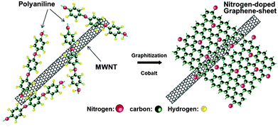 | ||
| Fig. 15 Scheme of the formation of nitrogen-doped graphene sheets derived from polyaniline and Co precursors using carbon nanotubes as a template. Copyrights reserved to the American Chemical Society.130 | ||
Anodes for lithium–air batteries
Lithium metal was considered as a promising anode for Li–air batteries due to its higher specific energy (3600 W h kg−1) and lower potential (−3.04 V vs. SHE).127 Therefore, dendrite formation on the surface of lithium metal during the charging–discharging decay of the performance of the battery is still a challenge for the real application of lithium metal as an anode after many years of research.1 This is because of the continuous formation of the SEI film and dead lithium on the surface of the lithium metal electrode.110 After extensive studies, researchers proposed three theories to understand the formation of the dendrites on the surface of the lithium metal. Among them, the first one is the SEI film theory, according to which lithium deposition is higher where the conductivity of the Li+ ions is higher, as presented in Fig. 16.133,134 The second point of interest for the formation of dendrites is the breaking sites of SEI film because of the energy difference. The third one is the structural defects present in the lithium metal as defects are higher in energy to accumulate more precipitated products.126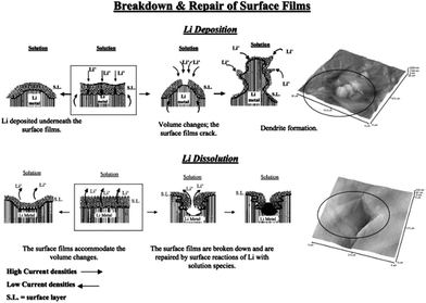 | ||
| Fig. 16 A description of the morphology and failure mechanisms of lithium electrodes during Li deposition and Li dissolution and relevant AFM images describing the selected phenomena: the beginning of dendrite formation and non-uniform Li dissolution accompanied by the breakdown and repair of the surface films (Li-electrodes in an EC-DMC/LiPF6 solution). Copyrights reserved to Elsevier Ltd.133 | ||
To date, there is no well-established way to use lithium metal as an anode safely and successfully, but many groups have done a lot of work to address these issues. A facile method is the coating of the anode with conductive films composed of lithium ion, but this methodology cannot ensure the total safety as these coatings are fragile and break in the charging–discharging processes.11,134 However, modifications are made on the basis of electrolyte solvents, additives, use of lithium salts, organic electrolytes. As the formation of LiF by the decomposition of the electrolyte can prevent the capacity fading, thus using electrolytes containing fluoride are helpful to prevent the formation of dendrites. However, the incorporation of lithium salts as LiPF6 and LiBF4 and additives like HF will also be helpful to decrease the formation of dendrites by producing LiF decomposition materials.135,136 Because of the mechanical strength and elastic behaviour of polymeric electrolytes, such as PEO (polyethylene oxide) and PVDF (poly(vinylideneflouride)), can also hinder the formation of dendrites.137 However, dendrites have the ability to penetrate in the polymeric sheets, so this method cannot completely get rid of dendrite formation. The SEI film consists of two layers, the inner layer made of Li2O and the outer layer composed of LiF, LiOH and Li2CO3. Thus, solid organic and inorganic electrolytes are alternative choices to control the problems of SEI films.138 As, the inorganic additives influence the inner and organic and polymeric additive have positive effects on the outer layer of SEI. Therefore, a lot of research needs to make the lithium-based anodes applicable in the Li–air batteries. Recently, Hassoun et al.11 reported a lithiated silicon-based anode for Li–air batteries with good stability and higher performance (Fig. 17). It is a good idea to make lithium-based materials applicable in the real Li–air batteries, but in such a case volume expansion and aggregation of the NPs is another problem that later becomes the reason for the lower performance that can be resolved using graphene as a mechanical and conductive buffer.
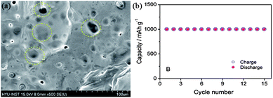 | ||
| Fig. 17 SEM image of lithiated silicon (yellow circles highlighting the SEI film). (b) Cyclic performance of a Li–air battery based on a lithiated silicon anode. Copyrights reserved to the American Chemical Society.11 | ||
Lithium–sulphur batteries
Lithium-based batteries are well known because of their high energy density and safety. However, existing batteries are not fulfilling the requirement of long time periods of storage because of their low energy densities. Therefore, another class of lithium-based batteries, known as “lithium–sulphur” batteries, has received much attention of researchers due to its low weight, safety and high energy density.139 If the heavy anodes of LIBs are changed by the low weight sulphur or its composites, the resultant batteries are called lithium–sulphur batteries. Because of its high theoretical capacity (1672 mA h g−1), sulphur has ability to replace the conventional electrode in the LIBs and is considered as a promising energy storage material in future batteries.140 The theoretical specific energy and volumetric energy densities are 2600 W h kg−1and 2800 W h L−1, respectively by considering the complete formation of Li2S, which is much higher than that of conventional LIBs.141 Other advantages of sulphur include low price, natural abundance and environmentally benignity, which make it appealing for second generation LIBs for use in EVs.142However, there are a lot hurdles that need to be overcome before the realization of lithium–sulphur batteries in EVs and other applications.143 Here, we will describe shortly the problems associated with lithium–sulphur batteries and how scientists tried to solve these issues by using different methodologies. The first problem is the low conductivity of sulphur (5 × 10⁻³⁰ S cm−1), which becomes the reason of low contact and the poor electrochemical performance of the sulphur electrode,8 resulting in the low capacity and capacity fading of the electrode. This problem can be solved by the incorporation of the high conductive substrates like the carbon and graphene to enhance the conductivity of the sulphur electrode.144,145 The second problem related to the sulphur is its volume change up to 76% during the charging and discharging process, which leads to the structural deterioration and break down in the morphology and decrease in electrode performance.146 This problem can be solved by the incorporation of elastically strong buffering materials that can prevent structural changes in the electrode, like the doping of inorganic elements and organic hybrid composites.146–149 The third major issue is related to the formation of polysulfide anions that can cause structural damage, low conductivity and by reaction with lithium cathode make the dendrites on the surface of the lithium electrode.139,150–152 Therefore, the performance and the capacity of the sulphur electrode are badly affected. The other issue related to these polysulfide anions is the concentration gradient by the production of high order polysulfide anions that move towards the cathode and react there on the surface of the lithium metal and produce low order polysulfide anions.153 Thus, there is a build up of a concentration gradient that moves across the battery called a polysulfide shuttle that greatly affects the performance.141 This problem can be solved by the incorporation of porous materials that can absorb these materials and prevent them from dissolving in the electrolyte organic solvents, or by modifying the electrolytes as solid electrolytes.142,143,149,154 All these problems are inter-related to each other, so we need to modify all the components of the lithium–sulphur battery including the cathode, anode, electrolytes and separator membranes.151,155,156
There have been many efforts made by different groups to enhance the capacity of the lithium–sulphur battery by incorporating, carbon, graphene and polymeric additives. Wang et al.146 reported the synthesis of micro porous carbon with a graphitic structure matrix to stabilize the structure of the sulphur electrode and enhance its capacity. As the size of polysulfide anions is small, there is a chance of their escape through the porous carbon and affecting the performance of the electrode. To overcome this problem, Yang et al.157 reported the coating of conductive polymer on sulphur for a better performance and for controlling the dissolution problem of the polysulfide anions, but still the escape of the polysulfide anions is not completely overcome. The 2D structure, high conductivity, porous and elastically strong nature of graphene received more attention of researchers to solve the above discussed problem associated with lithium–sulphur batteries. Secondly, the aromatic nature of graphene can act as a strong barrier in the flow of polysulfide anions. Jin et al.10 reported the synthesis of sulphur impregnated graphene paper that can improve the capacity retention of the sulphur electrode up to 83% by enhancing the conductivity and structural stability of the sulphur. Wang et al.140 reported a graphene sulphur composite with a unique architecture as they synthesized the polyethylene coated sulphur particles and GO decorated with carbon particles. Finally they combined this structure to one that can provide the control of polysulfide anions and maintain the conductivity and structural integrity of sulphur, resulting in high performance (Fig. 18).
 | ||
| Fig. 18 (a) Schematic presentation of the design architecture (b) TEM image of the graphene–PEG–sulphur composite (c) cyclic performance of the composite. Copyrights reserved to the American Chemical Society.140 | ||
Supercapacitors
The capacitors with higher energy, as well as power densities, are known as supercapacitors (also called ultracapacitors or electrochemical capacitors). This capacitance results as a consequence of electrostatic interactions via the physical accumulation of charge (electric double layer capacitor, EDLC) or Faradaic charge transfer that occurs through the reversible Faradaic redox reaction (pseudocapacitance) at the electrode–electrolyte interface.158,159 In EDLC, energy is stored through polarization followed by the adsorption of ionic charges on the surface of the electrode and hence the surface area of the electrode plays a major role.160,161 Because of the high surface area, porous structure, chemical inertness, and good electrical conductivity, carbon-based electrodes are promising contestants for supercapacitors.50,162 In contrast conducting polymers and metal oxides and hydroxides are promising candidates for pseudocapacitors because of their electrochemically active nature and their ability to carry out the Faradaic redox reaction.158,163,164 Low voltage windows are the major hurdle for carbon-based materials to fully utilize their large surface area to accumulate maximum charge and show higher capacitance.165 Organic electrolytes have been utilized to increase the operational voltage windows instead of aqueous electrolytes, but their low thermal stability causes capacity fading.166 In this regard, ionic electrolytes have shown interesting results with large organic ions, low vapour pressure, wide liquid range, high ionic conductivity, good electrochemical as well as thermal stability, along with its extensive potential window (normally, in between 3 and 7 V).160,167 Therefore, the performance of ionic electrolytes is adversely affected by the moisture, so a highly sophisticated moisture controlled process is required to utilize ionic electrolytes.14 However, this problem was successfully sorted out by the use of the hydrophobic ionic electrolytes.160 To enhance the performance of the capacitance of carbon based materials researchers utilized different morphologies e.g. wrinkled or 3D networks etc. and composites of different carbonaceous materials like graphene/carbon nanotubes (CNTs) or polymer etc.168–171 Yu et al.162 reported a graphene/CNTs composite, while keeping in mind the effect of surface area and conductivity for large specific capacitance and stable performance in aqueous electrolyte. They first modified the CNTs with polymer for good dispersion and as a result these CNTs had an enhanced surface area, electrochemical ability and conductivity of the composite. As, is well known the incorporation of heteroatoms to the graphene enhances its conductivity and electrochemical performance via interrupting its π-electron cloud.172 Han et al.159 reported high surface area B-doped graphene through a solution method for high performance supercapacitors. They utilized the effect that the doping of heteroatoms can change the electronic structure and density of state (DOS) significantly,173 thus modifying the quantum capacitance and leading to higher interfacial capacitance values. Therefore, the efficacious adsorption of electrolyte ions is a key factor to generate extraordinary specific capacitance.165 So for this purpose, Gao et al.14 reported the use of a graphene hydrogel that can provide a high surface area along with large spaces because of its high porosity. Cao et al.174 reported the synthesis of a 3D graphene network decorated with NiO2 to get the synergetic effect of high porosity with a large surface area, which makes the maximum access of electrolyte ions to the metal oxide for high capacitance and excellent durability. However, metal oxides have low conductivity issues that can also be resolved by making their composite with highly conductive graphene sheets to bring high performance supercapacitors into reality. Furthermore another additional problem of the low voltage operation of supercapacitors electrodes is a big hindrance in their practical applications. Recently, Chang et al.175 reported the synthesis of a graphene/metal oxide composite of two different metals as the positive (graphene/MnO2) and negative (graphene/MoO3) electrodes to increase the voltage window to obtain the maximum performance. The voltage window or working potential depends on the dissociation energy of the electrolyte. On the other hand, for asymmetric supercapacitors, the operation potential is determined by the work function difference of two metal oxides, similar to battery operation. Thus, the selection of two metal oxides with the largest work function difference is helpful for a wide operational voltage of supercapacitors as (graphene/MnO2) and (graphene/MoO3) systems. Recently, Ji et al.163 reported a beautiful work by constructing a 3D foam of graphene loaded with Ni(OH)2. The composite can successfully use the high mobility of electrons by graphene to Ni(OH)2 and porous Ni(OH)2 can shorten the diffusion path and as a result a high capacitance comes out (Fig. 19). In short, a highly porous with large surface area, elastically strong, conductive and electrochemically active graphene and its composites with high capacitance materials are extremely helpful in the realization of supercapacitors.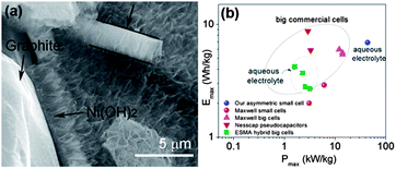 | ||
| Fig. 19 (a) TEM image of a cross section of the 3D graphene/Ni(OH)2 composite (b) Ragone plots of the asymmetric supercapacitor based on the full cell, compared with some high-end commercial supercapacitors. Copyrights reserved to the American Chemical Society.163 | ||
Oxygen reduction reaction for fuel cells
The fuel cell is a type of energy conversion device, which converts chemical energy to electrical energy by oxidizing the fuel catalysed by the catalysts immobilized on electrodes.1,176 Fuel cells have great potential as clean and efficient power sources for EVs due to their high energy conversion efficiency, low operation temperature, low or even zero emission, high energy and power density.35 However, the slow kinetics of the ORR (O2 + 4H+ + 4e− → 2H2O) is the major hindering factor in the energy conversion efficiency of fuel cells and their large-scale commercialization.5 Therefore, it is essential to develop an efficient electrocatalyst for the ORR at the cathode in fuel cells and even Li–air batteries.6,127,130 Conventionally, Pt-based materials have been recycled as active electrocatalysts for both anodes and cathodes in fuel cells. Although Pt-based materials have been considered as the best electrocatalyst for the ORR in fuel cells they still face a lot of hurdles. For example, Pt-based cathode electrocatalysts are subject to the crossover effect caused by the fuel molecules that diffuse from the anode side to the cathode through the membrane in fuel cells and CO poisoning that generates the carbonates precipitation and results in lowering the pH of the system.7,23,106 Furthermore, a major “bottleneck” in the market availability of the fuel cell technology is the high cost of Pt, together with its limited reserve in nature.46 To reduce the cost of a fuel cell it is necessary to replace the Pt with a metal or metal-free catalyst, and this has thus generated a great deal of interest.177To overcome these problems, nanostructured catalyst supports, such as different kinds of carbon (e.g. active carbon, porous carbon, carbon nanotubes, graphene etc.), mesoporous silica, carbides, conducting polymers and metals have been established to exploit the electroactive surface area of catalysts and enhance their catalytic activity with improved durability.4 Among these, graphene, a 2D single layer sheet of hexagonal carbon atoms, has emerged as a new generation catalyst support because of its high surface area, excellent electrical conductivity, good chemical and environmental stability and strong coupling with catalyst NPs.178 Despite the incredible progress in graphene-based catalysts for the ORR, there is another unique advantage of graphene: its controllable assembly to 3D networks with active NPs loadings as ORR catalysts.46 Such systems are attractive targets, as they permit the utilization of the distinctive topographies of graphene sheets, as well as the presence of macroporosity and multidimensional electron transport pathways.177,179
Both theoretical calculations and experiments have confirmed that the incorporation of heteroatoms (N, P, B) into sp2 hybridized carbon frameworks in graphene is generally effective in improving their electrical properties and chemical activities.23 Initially, it was proposed that the high activity may be attributed to the larger electronegativity of N (3.04) with respect to C atoms (2.55) and the formation of positive charge density on the adjacent C atoms.180 These factors may result in the favourable adsorption of O2.181 Very recently, other carbon materials doped with low electronegativity atoms, such as P-doped graphite layers (2.19) (ref. 182) and B-doped CNTs (2.04) (ref. 183), have also shown pronounced catalytic activity. It is very interesting to see the results when the doped element has a similar electronegativity to carbon. Sulphur (2.58) and selenium (2.55) have a close electronegativity to carbon (2.55) and were doped in graphene and used as a cathode for the ORR.184 The results showed that the electrocatalytic performances of the Se/S-doped graphene exhibited excellent catalytic activity, long-term stability, and high methanol tolerance in alkaline media for the ORR.24 Theoretical studies using simulation calculations have confirmed that breaking the electroneutrality of graphitic materials to create charged sites favourable for O2 adsorption is a key factor in enhancing ORR activity, regardless of dopant type.24,178 Obviously, tailoring the electronic arrangement of graphene by doping could be a practical strategy for producing significantly improved materials for the ORR in fuel cells.
A lot of research has tried to overcome the problems mentioned above and to enhance the performance of the electrocatalyst by using graphene as a conductive and elastically strong substrate to prevent the structural changes of cathodic materials. Many groups have worked even to explore graphene itself as a good cathodic catalyst for ORR by incorporating heteroatoms in the graphene. Zhang et al.23 reported a facile method to prepare N-doped graphene with amino functional groups for the cathodic ORR. The amino functional graphene has shown good performance with a better tolerance to the crossover effect of fuel. They also explored the effect of different nitrogen centres on the catalytic activity of the cathodic ORR. Therefore, the experimental results showed that the graphitic and amino types of nitrogen determine the onset potential and electron transfer number, while the total content of graphitic and pyridinic nitrogen atoms is involved in enhancing the current density in the electrocatalytic activity for the ORR (Fig. 20).180
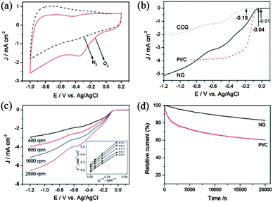 | ||
| Fig. 20 (a) CV curves of AG in a N2- and O2-saturated 0.1 M KOH solution at a scanning rate of 100 mV s−1. (b) LSV curves of CCG, Pt/C and AG electrodes in an O2-saturated 0.1 M KOH solution at a scanning rate of 10 mV s−1 and a rotation speed of 1600 rpm. (c) RDE curves of AG electrode in an O2-saturated 0.1 M KOH solution with different rotation speeds at a scanning rate of 10 mV s−1. Inset shows the K–L plots of J−1versus ω−1/2 at different electrode potentials derived from RDE measurements. (d) Current–time response of AG and Pt/C electrodes at 0.28 V in an O2-saturated 0.1 M KOH at a rotation speed of 1600 rpm. Copyrights reserved to Elsevier Ltd.23 | ||
Yang et al.24 prepared S-doped graphene and found that the electronegativity of the doping element is not important, but an important factor is the disruption of electroneutrality of graphitic planes which enhances the adsorption of O2 and becomes the center for oxygen catalysis, resulting in the enhanced performance of doped graphene. Mahmood et al.35 prepared the graphene-based cobalt sulphide composite and concluded that the existence of graphene enhanced the conductivity, provided a large surface area and functionalized centers for more O2 adsorption, resulting in higher ORR performance. They also explored catalysts for the ORR in acidic media. If the electrocatalyst was first treated with acid to remove the inactive species, it was helpful to increase their performance.
Zhang et al.6 reported an N-doped graphene composite with iron phthalocyanine (FePc) to present a new class of non-precious metal electrocatalysts. They explored that N-doping in graphene synergistically with FePc provides a large number of catalytically active centers to develop a electrocatalyst that has a high catalytic activity with superior conductivity, resulting in a better performance overall and a higher tolerance to fuel than commercial Pt/C as shown in Fig. 21. Zhang et al.172 also reported recently that the doping of phosphorus to the graphitic plane of graphene can enhance the oxygen reduction on the cathode of fuel cells better than ordinary graphene as phosphorus can activate the neutral π-electronic cloud of graphene. Wu et al.46 opened up a new path to improve the catalytic performance of electrocatalysts by designing 3D networks of graphene that provide a larger surface area and multidimensional passage for O2 flow than the conventional 2D graphene sheets, as shown in Fig. 22. So using such a strategy like the 3D support of electrochemically active and conductive substrates with high performance non-precious electrocatalysts will aid in the realization of fuel cells in the future.
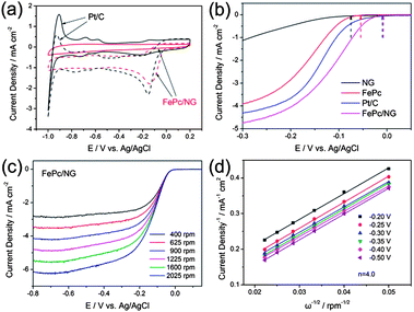 | ||
| Fig. 21 (a) CV curves of Pt/C (black) and FePc/N-doped graphene (red) catalysts in O2-saturated (dotted) or N2-saturated (solid) 0.1 M KOH. (b) LSV curves of the N-doped graphene, FePc, Pt/C and FePc/N-doped graphene electrodes in O2-saturated 0.1 M KOH at a scan rate of 10 mV s−1 and at a rotation speed of 1600 rpm. (c) RDE curves of FePc/N-doped graphene in O2-saturated 0.1 M KOH with different speeds at a scan rate of 10 mV s−1. (d) The K–L plots of the FePc/N-doped graphene electrode derived from RDE measurements. Copyrights reserved to the Royal Society of Chemistry.6 | ||
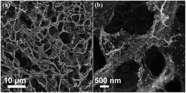 | ||
| Fig. 22 SEM images of (a) 3D graphene and (b) 3D graphene composited with Fe3O4. Copyrights reserved to the American Chemical Society.46 | ||
Conclusion and outlook
Graphene displays an exceptional chemical structure, and outstanding electronic, optical, thermal and mechanical properties. A large number of synthetic methods have been established to synthesize high quality graphene including chemical and physical strategies in order to meet the increasing demands for thin film processing, composite incorporation and device integration. Numerous materials have been composited with graphene, such as polymers, NPs of semiconductor, metals, metal oxides, sulphides, alloys, CNTs, organic materials etc. The enhancement in the properties of these composited materials not only depends on the individual components, but also on the interactions between them. Therefore, to improve the properties of graphene-based materials, it is necessary to control the distribution, density, kinds of chemical bonds, as well as three dimensional arrangements of the composites. Thus, various assembly methodologies have been developed for the constant demand of property optimization; the particular efforts are directed towards the design and formation of specially constructed hybrid architectures rather than random mixtures. More effort should be directed to effectively enlarge the specific surface area, porosity, reduce the O/C ratio and increase the conductivity of the electrode. Although there is a lot of research regarding the manipulation of the properties of graphene-based materials, there are still some issues present like the low specific surface area and conductivity of the composites. During the composite formation, graphene layers restacked and the actual surface area of the graphene is not exposed. This problem can be solved by designing the unique morphology that can prevent the restacking of graphene and exposed its surface, also by incorporating the heteroatoms that can increase the conductivity and electrochemical performance. There are a lot of reports in which the doping of different elements (N, S, Se, P, B) and the 3D architecture tackled this problem.46 Secondly, the stability of graphene-based composites in LIBs or supercapacitors decreases during lithium and/or electrolyte insertion and extraction. Thus, it is necessary to modify the chemical or physical interactions of the NPs with graphene so as to stabilize the structure in real applications. Zhou et al.33 reported the binding of SnO2 NPs on graphene sheets through the Sn–N–C and Sn–O–C bonds to overcome the structural changes and aggregation of NPs. Researchers have solved a lot of the bottlenecks in applying graphene and graphene-based materials in energy systems, but their working mechanisms are only partly clear. After completely understanding and resolving the aforementioned problems regarding graphene, a revolution of clean and renewable energy materials and devices will be realized.Acknowledgements
This work was supported by the NSFC (51125001, 51172005), Beijing Natural Science Foundation (2122022), Aerostatic Science Foundation (2010ZF71003), New Century Excellent Talent of the Ministry of Education of China (NCET-09-0177) and Fok Ying Tong Foundation (122043).Notes and references
- Y. Sun, Q. Wu and G. Shi, Energy Environ. Sci., 2011, 4, 1113 CAS.
- J.-T. Chen and C.-S. Hsu, Polym. Chem., 2011, 2, 2707 RSC.
- X. Liu, F. Wang and Q. Wang, Phys. Chem. Chem. Phys., 2012, 14, 7894–7911 RSC.
- E. H. Yu, X. Wang, U. Krewer, L. Li and K. Scott, Energy Environ. Sci., 2012, 5, 5668 CAS.
- Z.-Y. Shih, A. P. Periasamy, P.-C. Hsu and H.-T. Chang, Appl. Catal., B, 2013, 132–133, 363–369 CrossRef CAS.
- C. Zhang, R. Hao, H. Yin, F. Liu and Y. Hou, Nanoscale, 2012, 4, 7326–7329 RSC.
- J. Hou, Z. Liu and P. Zhang, J. Power Sources, 2013, 224, 139–144 CrossRef CAS.
- D. Wang, Q. Zeng, G. Zhou, L. Yin, F. Li, H.-M. h. Cheng, I. Gentle and G. Q. Lu, J. Mater. Chem. A, 2013, 1, 9382–9394 CAS.
- G. Girishkumar, B. McCloskey, A. C. Luntz, S. Swanson and W. Wilcke, J. Phys. Chem. Lett., 2010, 1, 2193–2203 CrossRef CAS.
- J. Jin, Z. Wen, G. Ma, Y. Lu, Y. Cui, M. Wu, X. Liang and X. Wu, RSC Adv., 2013, 3, 2558 RSC.
- J. Hassoun, H. G. Jung, D. J. Lee, J. B. Park, K. Amine, Y. K. Sun and B. Scrosati, Nano Lett., 2012, 12, 5775–5779 CrossRef CAS PubMed.
- A. Pan, H. B. Wu, L. Yu and X. W. Lou, Angew. Chem., Int. Ed., 2013, 52, 2226–2230 CrossRef CAS PubMed.
- S. J. Yang, S. Nam, T. Kim, J. H. Im, H. Jung, J. H. Kang, S. Wi, B. Park and C. R. Park, J. Am. Chem. Soc., 2013, 135, 7394–7397 CrossRef CAS PubMed.
- H. Gao, F. Xiao, C. B. Ching and H. Duan, ACS Appl. Mater. Interfaces, 2012, 4, 2801–2810 CAS.
- B. Wang, X. Li, X. Zhang, B. Luo, Y. Zhang and L. Zhi, Adv. Mater., 2013, 25, 3560–3565 CrossRef CAS PubMed.
- L. Zhang, G. Zhang, H. B. Wu, L. Yu and X. W. Lou, Adv. Mater., 2013, 25, 2589–2593 CrossRef CAS PubMed.
- Z.-S. Wu, W. Ren, L. Xu, F. Li and H.-M. Cheng, ACS Nano, 2011, 5, 5463–5471 CrossRef CAS PubMed.
- H. Wang, T. Maiyalagan and X. Wang, ACS Catal., 2012, 2, 781–794 CrossRef CAS.
- N. O. Weiss, H. Zhou, L. Liao, Y. Liu, S. Jiang, Y. Huang and X. Duan, Adv. Mater., 2012, 24, 5782–5825 CrossRef CAS PubMed.
- X. Huang, Z. Yin, S. Wu, X. Qi, Q. He, Q. Zhang, Q. Yan, F. Boey and H. Zhang, Small, 2011, 7, 1876–1902 CrossRef CAS PubMed.
- W. Qian, R. Hao, Y. Hou, Y. Tian, C. Shen, H. Gao and X. Liang, Nano Res., 2009, 2, 706–712 CrossRef CAS.
- X. Cui, C. Zhang, R. Hao and Y. Hou, Nanoscale, 2011, 3, 2118–2126 RSC.
- C. Zhang, R. Hao, H. Liao and Y. Hou, Nano Energy, 2013, 2, 88–97 CrossRef CAS.
- Z. Yang, Z. Yao, G. Li, G. Fang, H. Nie, Z. Liu, X. Zhou, X. a. Chen and S. Huang, ACS Nano, 2012, 6, 205–211 CrossRef CAS PubMed.
- Y. Zheng, Y. Jiao, L. Ge, M. Jaroniec and S. Z. Qiao, Angew. Chem., Int. Ed., 2013, 52, 3110–3116 CrossRef CAS PubMed.
- A. L. M. Reddy, A. Srivastava, S. R. Gowda, H. Gullapalli, M. Dubey and P. M. Ajayan, ACS Nano, 2010, 4, 6337–6342 CrossRef CAS PubMed.
- D.-J. Xue, S. Xin, Y. Yan, K.-C. Jiang, Y.-X. Yin, Y.-G. Guo and L.-J. Wan, J. Am. Chem. Soc., 2012, 134, 2512–2515 CrossRef CAS PubMed.
- Y. J. Mai, J. P. Tu, C. D. Gu and X. L. Wang, J. Power Sources, 2012, 209, 1–6 CrossRef CAS.
- B. Fuchsbichler, C. Stangl, H. Kren, F. Uhlig and S. Koller, J. Power Sources, 2011, 196, 2889–2892 CrossRef CAS.
- Z.-S. Wu, W. Ren, L. Wen, L. Gao, J. Zhao, Z. Chen, G. Zhou, F. Li and H.-M. Cheng, ACS Nano, 2010, 4, 3187–3194 CrossRef CAS PubMed.
- Y. Sun, X. Hu, W. Luo and Y. Huang, ACS Nano, 2011, 5, 7100–7107 CrossRef CAS PubMed.
- Z. Du, X. Yin, M. Zhang, Q. Hao, Y. Wang and T. Wang, Mater. Lett., 2010, 64, 2076–2079 CrossRef CAS.
- X. Zhou, L. J. Wan and Y. G. Guo, Adv. Mater., 2013, 25, 2152–2157 CrossRef CAS PubMed.
- N. Mahmood, C. Zhang and Y. Hou, Small, 2013, 9, 1321–1328 CrossRef CAS PubMed.
- N. Mahmood, C. Zhang, J. Jiang, F. Liu and Y. Hou, Chem.–Eur. J., 2013, 19, 5183–5190 CrossRef CAS PubMed.
- J. Xiao, X. Wang, X.-Q. Yang, S. Xun, G. Liu, P. K. Koech, J. Liu and J. P. Lemmon, Adv. Funct. Mater., 2011, 21, 2840–2846 CrossRef CAS.
- B. Luo, Y. Fang, B. Wang, J. Zhou, H. Song and L. Zhi, Energy Environ. Sci., 2012, 5, 5226 CAS.
- N.-S. Choi, Y. Yao, Y. Cui and J. Cho, J. Mater. Chem., 2011, 21, 9825 RSC.
- P. Chen, L. Guo and Y. Wang, J. Power Sources, 2013, 222, 526–532 CrossRef CAS.
- K. Zhang, L. L. Zhang, X. S. Zhao and J. Wu, Chem. Mater., 2010, 22, 1392–1401 CrossRef CAS.
- E. Pollak, B. Geng, K.-J. Jeon, I. T. Lucas, T. J. Richardson, F. Wang and R. Kostecki, Nano Lett., 2010, 10, 3386–3388 CrossRef CAS PubMed.
- Z. Jin, J. Yao, C. Kittrell and J. M. Tour, ACS Nano, 2011, 5, 4112–4117 CrossRef CAS PubMed.
- R. C. Haddon, Acc. Chem. Res., 2013, 46, 1–3 CrossRef CAS PubMed.
- X. Xin, X. Zhou, J. Wu, X. Yao and Z. Liu, ACS Nano, 2012, 6, 11035–11043 CrossRef CAS PubMed.
- G. Zhou, D.-W. Wang, L.-C. Yin, N. Li, F. Li and H.-M. Cheng, ACS Nano, 2012, 6, 3214–3223 CrossRef CAS PubMed.
- Z. S. Wu, S. Yang, Y. Sun, K. Parvez, X. Feng and K. Mullen, J. Am. Chem. Soc., 2012, 134, 9082–9085 CrossRef CAS PubMed.
- H. Zhao, L. Pan, S. Xing, J. Luo and J. Xu, J. Power Sources, 2013, 222, 21–31 CrossRef CAS.
- B. Luo, B. Wang, M. Liang, J. Ning, X. Li and L. Zhi, Adv. Mater., 2012, 24, 1405–1409 CrossRef CAS PubMed.
- B. Luo, B. Wang, X. Li, Y. Jia, M. Liang and L. Zhi, Adv. Mater., 2012, 24, 3538–3543 CrossRef CAS PubMed.
- Z.-D. Huang, B. Zhang, S.-W. Oh, Q.-B. Zheng, X.-Y. Lin, N. Yousefi and J.-K. Kim, J. Mater. Chem., 2012, 22, 3591 RSC.
- A. A. Green and M. C. Hersam, J. Phys. Chem. Lett., 2010, 1, 544–549 CrossRef CAS PubMed.
- Y. Zhang, T.-T. Tang, C. Girit, Z. Hao, M. C. Martin, A. Zettl, M. F. Crommie, Y. R. Shen and F. Wang, Nature, 2009, 459, 820–823 CrossRef CAS PubMed.
- M. F. Craciun, S. Russo, M. Yamamoto, J. B. Oostinga, A. F. Morpurgo and S. Tarucha, Nat. Nanotechnol., 2009, 4, 383–388 CrossRef CAS PubMed.
- Y. H. Lu and Y. P. Feng, J. Phys. Chem. C, 2009, 113, 20841–20844 CAS.
- A. Sinitskii, A. A. Fursina, D. V. Kosynkin, A. L. Higginbotham, D. Natelson and J. M. Tour, Appl. Phys. Lett., 2009, 95, 253108-3 CrossRef.
- C. Stampfer, J. Guttinger, S. Hellmuller, F. Molitor, K. Ensslin and T. Ihn, Phys. Rev. Lett., 2009, 102, 056403–056403 CrossRef CAS PubMed.
- K. S. Novoselov, A. K. Geim, S. V. Morozov, D. Jiang, Y. Zhang, S. V. Dubonos, I. V. Grigorieva and A. A. Firsov, Science, 2004, 306, 666–669 CrossRef CAS PubMed.
- C. Berger, Z. Song, X. Li, X. Wu, N. Brown, C. Naud, D. Mayou, T. Li, J. Hass, A. N. Marchenkov, E. H. Conrad, P. N. First and W. A. de Heer, Science, 2006, 312, 1191–1196 CrossRef CAS PubMed.
- Y. Pan, H. Zhang, D. Shi, J. Sun, S. Du, F. Liu and H.-j. Gao, Adv. Mater., 2009, 21, 2777–2780 CrossRef CAS.
- K. S. Kim, Y. Zhao, H. Jang, S. Y. Lee, J. M. Kim, K. S. Kim, J.-H. Ahn, P. Kim, J.-Y. Choi and B. H. Hong, Nature, 2009, 457, 706–710 CrossRef CAS PubMed.
- S. Yongchao and E. T. Samulski, Nano Lett., 2008, 8, 1679–1682 CrossRef PubMed.
- Y. Xu, H. Bai, G. Lu, C. Li and G. Shi, J. Am. Chem. Soc., 2008, 130, 5856–5857 CrossRef CAS PubMed.
- X. Li, X. Wang, L. Zhang, S. Lee and H. Dai, Science, 2008, 319, 1229–1232 CrossRef CAS PubMed.
- X. Li, G. Zhang, X. Bai, X. Sun, X. Wang, E. Wang and H. Dai, Nat. Nanotechnol., 2008, 3, 538–542 CrossRef CAS PubMed.
- Y. Hernandez, V. Nicolosi, M. Lotya, F. M. Blighe, Z. Sun, S. De, I. T. McGovern, B. Holland, M. Byrne, Y. K. Gun'ko, J. J. Boland, P. Niraj, G. Duesberg, S. Krishnamurthy, R. Goodhue, J. Hutchison, V. Scardaci, A. C. Ferrari and J. N. Coleman, Nat. Nanotechnol., 2008, 3, 563–568 CrossRef CAS PubMed.
- L. Na, L. Fang, W. Haoxi, L. Yinghui, Z. Chao and C. Ji, Adv. Funct. Mater., 2008, 18, 1518–1525 CrossRef.
- C. Valles, C. Drummond, H. Saadaoui, C. A. Furtado, M. He, O. Roubeau, L. Ortolani, M. Monthioux and A. Penicaud, J. Am. Chem. Soc., 2008, 130, 15802–15804 CrossRef CAS PubMed.
- Z. Peng, Z. Sun, Y. Zhu, L. Li, C. Xiang, E. L. Samuel, C. Kittrell and J. M. Tour, ACS Nano, 2013, 7, 875–875 CrossRef PubMed.
- G. Cravotto and P. Cintas, Chem.–Eur. J., 2010, 16, 5246–5259 CrossRef CAS PubMed.
- Z. Tang, J. Zhuang and X. Wang, Langmuir, 2010, 26, 9045–9049 CrossRef CAS PubMed.
- Y. Zhang, L. Zhang, P. Kim, M. Ge, Z. Li and C. Zhou, Nano Lett., 2012, 12, 2810–2816 CrossRef CAS PubMed.
- X. Huang, Z. Zeng, Z. Fan, J. Liu and H. Zhang, Adv. Mater., 2012, 24, 5979–6004 CrossRef CAS PubMed.
- T. Bansal, C. A. Durcan, N. Jain, R. B. Jacobs-Gedrim, Y. Xu and B. Yu, Carbon, 2013, 55, 168–175 CrossRef CAS.
- D. A. Brownson and C. E. Banks, Phys. Chem. Chem. Phys., 2012, 14, 8264–8281 RSC.
- Y. Zhu, D. K. James and J. M. Tour, Adv. Mater., 2012, 24, 4924–4955 CrossRef CAS PubMed.
- M. H. Ruemmeli, C. G. Rocha, F. Ortmann, I. Ibrahim, H. Sevincli, F. Boerrnert, J. Kunstmann, A. Bachmatiuk, M. Poetschke, M. Shiraishi, M. Meyyappan, B. Buechner, S. Roche and G. Cuniberti, Adv. Mater., 2011, 23, 4471–4490 CrossRef CAS.
- M. Lotya, P. J. King, U. Khan, S. De and J. N. Coleman, ACS Nano, 2010, 4, 3155–3162 CrossRef CAS PubMed.
- M. Lotya, Y. Hernandez, P. J. King, R. J. Smith, V. Nicolosi, L. S. Karlsson, F. M. Blighe, S. De, Z. Wang, I. T. McGovern, G. S. Duesberg and J. N. Coleman, J. Am. Chem. Soc., 2009, 131, 3611–3620 CrossRef CAS PubMed.
- Z. Ming, R. R. Parajuli, D. Mastrogiovanni, D. Boya, P. Lo, W. Cheung, R. Brukh, C. Pui Lam, Z. Tao, L. Zhongfan, E. Garfunkel and H. Huixin, Small, 2010, 6, 1100–1107 CrossRef PubMed.
- J. Hou, Y. Shao, M. W. Ellis, R. B. Moore and B. Yi, Phys. Chem. Chem. Phys., 2011, 13, 15384–15402 RSC.
- W. W. Liu and J. N. Wang, Chem. Commun., 2011, 47, 6888–6890 RSC.
- U. Khan, A. O'Neill, M. Lotya, S. De and J. N. Coleman, Small, 2010, 6, 864–871 CrossRef CAS PubMed.
- S. Some, J. Kim, K. Lee, A. Kulkarni, Y. Yoon, S. Lee, T. Kim and H. Lee, Adv. Mater., 2012, 24, 5481–5486 CrossRef CAS PubMed.
- X. Li, L. Fan, Z. Li, K. Wang, M. Zhong, J. Wei, D. Wu and H. Zhu, Adv. Energy Mater., 2012, 2, 425–429 CrossRef CAS.
- W. Qian, X. Cui, R. Hao, Y. Hou and Z. Zhang, ACS Appl. Mater. Interfaces, 2011, 3, 2259–2264 CAS.
- B. Luo, S. Liu and L. Zhi, Small, 2012, 8, 630–646 CrossRef CAS PubMed.
- C. Xu, B. Xu, Y. Gu, Z. Xiong, J. Sun and X. S. Zhao, Energy Environ. Sci., 2013, 6, 1388 CAS.
- Y. Lin, X. Li, D. Xie, T. Feng, Y. Chen, R. Song, H. Tian, T. Ren, M. Zhong, K. Wang and H. Zhu, Energy Environ. Sci., 2013, 6, 108 CAS.
- X. Huang, X. Qi, F. Boey and H. Zhang, Chem. Soc. Rev., 2012, 41, 666–686 RSC.
- D. A. Brownson, D. K. Kampouris and C. E. Banks, Chem. Soc. Rev., 2012, 41, 6944–6976 RSC.
- C. Wang, X. Han, P. Xu, X. Zhang, Y. Du, S. Hu, J. Wang and X. Wang, Appl. Phys. Lett., 2011, 98, 072906 CrossRef.
- T. Ohzuku and R. J. Brodd, J. Power Sources, 2007, 174, 449–456 CrossRef CAS.
- T. M. Bandhauer, S. Garimella and T. F. Fuller, J. Electrochem. Soc., 2011, 158, R1 CrossRef CAS.
- A. S. Arico, P. Bruce, B. Scrosati, J.-M. Tarascon and W. van Schalkwijk, Nat. Mater., 2005, 4, 366–377 CrossRef CAS PubMed.
- C. M. Hayner, X. Zhao and H. H. Kung, Annu. Rev. Chem. Biomol. Eng., 2012, 3, 445–471 CrossRef CAS PubMed.
- Y. Idota, T. Kubota, A. Matsufuji, Y. Maekawa and T. Miyasaka, Science, 1997, 276, 1395–1397 CrossRef CAS.
- M. Ge, J. Rong, X. Fang and C. Zhou, Nano Lett., 2012, 12, 2318–2323 CrossRef CAS PubMed.
- X. H. Liu, S. Huang, S. T. Picraux, J. Li, T. Zhu and J. Y. Huang, Nano Lett., 2011, 11, 3991–3997 CrossRef CAS PubMed.
- X. Zhou, Y.-X. Yin, L.-J. Wan and Y.-G. Guo, Chem. Commun., 2012, 48, 2198 RSC.
- L. Zhuo, Y. Wu, L. Wang, Y. Yu, X. Zhang and F. Zhao, RSC Adv., 2012, 2, 5084 RSC.
- B. Qu, M. Zhang, D. Lei, Y. Zeng, Y. Chen, L. Chen, Q. Li, Y. Wang and T. Wang, Nanoscale, 2011, 3, 3646–3651 RSC.
- C. Zhang, R. Hao, H. Liao and Y. Hou, Nano Energy, 2013, 2, 88–97 CrossRef CAS.
- Z.-L. Wang, D. Xu, H.-G. Wang, Z. Wu and X.-B. Zhang, ACS Nano, 2013, 7, 2422–2430 CrossRef CAS PubMed.
- W. Shi, J. Zhu, X. Rui, X. Cao, C. Chen, H. Zhang, H. H. Hng and Q. Yan, ACS Appl. Mater. Interfaces, 2012, 4, 2999–3006 CAS.
- Q. Wang, L. Jiao, Y. Han, H. Du, W. Peng, Q. Huan, D. Song, Y. Si, Y. Wang and H. Yuan, J. Phys. Chem. C, 2011, 115, 8300–8304 CAS.
- L. Zhu, D. Susac, M. Teo, K. Wong, P. Wong, R. Parsons, D. Bizzotto, K. Mitchell and S. Campbell, J. Catal., 2008, 258, 235–242 CrossRef CAS.
- B. Zhang, Q. B. Zheng, Z. D. Huang, S. W. Oh and J. K. Kim, Carbon, 2011, 49, 4524–4534 CrossRef CAS.
- B. Wang, X. Li, X. Zhang, B. Luo, M. Jin, M. Liang, S. A. Dayeh, S. T. Picraux and L. Zhi, ACS Nano, 2013, 7, 1437–1445 CrossRef CAS PubMed.
- D. Cai, D. Li, S. Wang, X. Zhu, W. Yang, S. Zhang and H. Wang, J. Alloys Compd., 2013, 561, 54–58 CrossRef CAS.
- N. Mahmood, C. Zhang and Y. Hou, Small, 2013, 9, 1321–1328 CrossRef CAS PubMed.
- N. H. Idris, M. M. Rahman, S.-L. Chou, J.-Z. Wang, D. Wexler and H.-K. Liu, Electrochim. Acta, 2011, 58, 456–462 CrossRef CAS.
- J. Jiang, W. Liu, J. Chen and Y. Hou, ACS Appl. Mater. Interfaces, 2012, 4, 3062–3068 CAS.
- X.-L. Wu, L.-Y. Jiang, F.-F. Cao, Y.-G. Guo and L.-J. Wan, Adv. Mater., 2009, 21, 2710–2714 CrossRef CAS.
- C. Wang, D. Li, C. O. Too and G. G. Wallace, Chem. Mater., 2009, 21, 2604–2606 CrossRef CAS.
- D. Su, H. S. Kim, W. S. Kim and G. Wang, Chem.–Eur. J., 2012, 18, 8224–8229 CrossRef CAS PubMed.
- C. Venkateswara Rao, A. Leela Mohana Reddy, Y. Ishikawa and P. M. Ajayan, ACS Appl. Mater. Interfaces, 2011, 3, 2966–2972 Search PubMed.
- J. Liu, Y. Wan, W. Liu, Z. Ma, S. Ji, J. Wang, Y. Zhou, P. Hodgson and Y. Li, J. Mater. Chem. A, 2013, 1, 1969 CAS.
- C. Nethravathi, C. R. Rajamathi, M. Rajamathi, U. K. Gautam, X. Wang, D. Golberg and Y. Bando, ACS Appl. Mater. Interfaces, 2013, 5, 2708–2714 CAS.
- X. Xiang, Z. Huang, E. Liu, H. Shen, Y. Tian, H. Xie, Y. Wu and Z. Wu, Electrochim. Acta, 2011, 56, 9350–9356 CrossRef CAS.
- Z. Song, T. Xu, M. L. Gordin, Y. B. Jiang, I. T. Bae, Q. Xiao, H. Zhan, J. Liu and D. Wang, Nano Lett., 2012, 12, 2205–2211 CrossRef CAS PubMed.
- L. Shao, J.-W. Jeon and J. L. Lutkenhaus, Chem. Mater., 2012, 24, 181–189 CrossRef CAS.
- J. Deng, H. Ji, C. Yan, J. Zhang, W. Si, S. Baunack, S. Oswald, Y. Mei and O. G. Schmidt, Angew. Chem., Int. Ed., 2013, 52, 2326–2330 CrossRef CAS PubMed.
- J. Xiao, D. Mei, X. Li, W. Xu, D. Wang, G. L. Graff, W. D. Bennett, Z. Nie, L. V. Saraf, I. A. Aksay, J. Liu and J. G. Zhang, Nano Lett., 2011, 11, 5071–5078 CrossRef CAS PubMed.
- L. Wang, M. Ara, K. Wadumesthrige, S. Salley and K. Y. S. Ng, J. Power Sources, 2013, 234, 8–15 CrossRef CAS.
- R. E. Williford and J.-G. Zhang, J. Power Sources, 2009, 194, 1164–1170 CrossRef CAS.
- Y. Shao, F. Ding, J. Xiao, J. Zhang, W. Xu, S. Park, J.-G. Zhang, Y. Wang and J. Liu, Adv. Funct. Mater., 2013, 23, 987–1004 CrossRef CAS.
- F. Li, T. Zhang and H. Zhou, Energy Environ. Sci., 2013, 6, 1125 CAS.
- X. Ren, S. S. Zhang, D. T. Tran and J. Read, J. Mater. Chem., 2011, 21, 10118 RSC.
- L. Li and A. Manthiram, J. Mater. Chem. A, 2013, 1, 5121 CAS.
- G. Wu, N. H. Mack, W. Gao, S. Ma, R. Zhong, J. Han, J. K. Baldwin and P. Zelenay, ACS Nano, 2012, 6, 9764–9776 CrossRef CAS PubMed.
- R. Younesi, S. Urbonaite, K. Edström and M. Hahlin, J. Phys. Chem. C, 2012, 116, 20673–20680 CAS.
- T. Zhang, N. Imanishi, Y. Shimonishi, A. Hirano, Y. Takeda, O. Yamamoto and N. Sammes, Chem. Commun., 2010, 46, 1661–1663 RSC.
- D. Aurbach, E. Zinigrad, Y. Cohen and H. Teller, Solid State Ionics, 2002, 148, 405–416 CrossRef CAS.
- L. Gireaud, S. Grugeon, S. Laruelle, B. Yrieix and J. M. Tarascon, Electrochem. Commun., 2006, 8, 1639–1649 CrossRef CAS.
- D. Aurbach, A. Zaban, Y. Gofer, Y. E. Ely, I. Weissman, O. Chusid and O. Abramson, J. Power Sources, 1995, 54, 76–84 CrossRef CAS.
- D. Aurbach, Y. Eineli, B. Markovsky, A. Zaban, S. Luski, Y. Carmeli and H. Yamin, J. Electrochem. Soc., 1995, 142, 2882–2890 CrossRef CAS.
- L. Sannier, R. Bouchet, L. Santinacci, S. Grugeon and J. M. Tarascon, J. Electrochem. Soc., 2004, 151, A873–A879 CrossRef CAS.
- H. Ohta, T. Mizoguchi, N. Aoki, T. Yamamoto, A. Sabarudin and T. Umemura, Appl. Phys. Lett., 2012, 100, 173107 CrossRef.
- A. Manthiram, Y. Fu and Y.-S. Su, Acc. Chem. Res., 2013, 46, 1125–1134 CrossRef CAS PubMed.
- H. Wang, Y. Yang, Y. Liang, J. T. Robinson, Y. Li, A. Jackson, Y. Cui and H. Dai, Nano Lett., 2011, 11, 2644–2647 CrossRef CAS PubMed.
- M. K. Song, E. J. Cairns and Y. Zhang, Nanoscale, 2013, 5, 2186–2204 RSC.
- Y.-X. Wang, L. Huang, L.-C. Sun, S.-Y. Xie, G.-L. Xu, S.-R. Chen, Y.-F. Xu, J.-T. Li, S.-L. Chou, S.-X. Dou and S.-G. Sun, J. Mater. Chem., 2012, 22, 4744 RSC.
- M. Zhang, D. Lei, X. Yu, L. Chen, Q. Li, Y. Wang, T. Wang and G. Cao, J. Mater. Chem., 2012, 22, 23091 RSC.
- B. Ding, C. Yuan, L. Shen, G. Xu, P. Nie, Q. Lai and X. Zhang, J. Mater. Chem. A, 2013, 1, 1096 CAS.
- G. Zheng, Q. Zhang, J. J. Cha, Y. Yang, W. Li, Z. W. Seh and Y. Cui, Nano Lett., 2013, 13, 1265–1270 CrossRef CAS PubMed.
- D. W. Wang, G. Zhou, F. Li, K. H. Wu, G. Q. Lu, H. M. Cheng and I. R. Gentle, Phys. Chem. Chem. Phys., 2012, 14, 8703–8710 RSC.
- M. S. Park, J. S. Yu, K. J. Kim, G. Jeong, J. H. Kim, Y. N. Jo, U. Hwang, S. Kang, T. Woo and Y. J. Kim, Phys. Chem. Chem. Phys., 2012, 14, 6796–6804 RSC.
- D. Li, F. Han, S. Wang, F. Cheng, Q. Sun and W. C. Li, ACS Appl. Mater. Interfaces, 2013, 5, 2208–2213 CAS.
- L. Yin, J. Wang, F. Lin, J. Yang and Y. Nuli, Energy Environ. Sci., 2012, 5, 6966 CAS.
- J. Kim, D.-J. Lee, H.-G. Jung, Y.-K. Sun, J. Hassoun and B. Scrosati, Adv. Funct. Mater., 2013, 23, 1076–1080 CrossRef CAS.
- N. Li, M. Zheng, H. Lu, Z. Hu, C. Shen, X. Chang, G. Ji, J. Cao and Y. Shi, Chem. Commun., 2012, 48, 4106–4108 RSC.
- C. Liang, N. J. Dudney and J. Y. Howe, Chem. Mater., 2009, 21, 4724–4730 CrossRef CAS.
- T. Lin, Y. Tang, Y. Wang, H. Bi, Z. Liu, F. Huang, X. Xie and M. Jiang, Energy Environ. Sci., 2013, 6, 1283 CAS.
- M. Nagao, A. Hayashi and M. Tatsumisago, Energy Technol., 2013, 1, 186–192 CrossRef CAS.
- J. Gao, M. A. Lowe, Y. Kiya and H. D. Abruña, J. Phys. Chem. C, 2011, 115, 25132–25137 CAS.
- L. Zhang, L. Ji, P. A. Glans, Y. Zhang, J. Zhu and J. Guo, Phys. Chem. Chem. Phys., 2012, 14, 13670–13675 RSC.
- Y. Yang, G. Yu, J. J. Cha, H. Wu, M. Vosgueritchian, Y. Yao, Z. Bao and Y. Cui, ACS Nano, 2011, 5, 9187–9193 CrossRef CAS PubMed.
- C. Liu, Z. Yu, D. Neff, A. Zhamu and B. Z. Jang, Nano Lett., 2010, 10, 4863–4868 CrossRef CAS PubMed.
- J. Han, L. L. Zhang, S. Lee, J. Oh, K.-S. Lee, J. R. Potts, J. Ji, X. Zhao, R. S. Ruoff and S. Park, ACS Nano, 2013, 7, 19–26 CrossRef CAS PubMed.
- P. Tamailarasan and S. Ramaprabhu, J. Phys. Chem. C, 2012, 116, 14179–14187 CAS.
- Z.-D. Huang, B. Zhang, R. Liang, Q.-B. Zheng, S. W. Oh, X.-Y. Lin, N. Yousefi and J.-K. Kim, Carbon, 2012, 50, 4239–4251 CrossRef CAS.
- D. Yu and L. Dai, J. Phys. Chem. Lett., 2010, 1, 467–470 CrossRef CAS.
- J. Ji, L. L. Zhang, H. Ji, Y. Li, X. Zhao, X. Bai, X. Fan, F. Zhang and R. S. Ruoff, ACS Nano, 2013, 7, 6237–6243 CrossRef CAS PubMed.
- C. Qian, T. Jie, N. Shinya and Q. Lu-Chang, J. Power Sources, 2013, 241, 423–428 CrossRef.
- Y. Wang, Z. Shi, Y. Huang, Y. Ma, C. Wang, M. Chen and Y. Chen, J. Phys. Chem. C, 2009, 113, 13103–13107 CAS.
- W. Lu, L. Qu, K. Henry and L. Dai, J. Power Sources, 2009, 189, 1270–1277 CrossRef CAS.
- C. Fu, Y. Kuang, Z. Huang, X. Wang, Y. Yin, J. Chen and H. Zhou, J. Solid State Electrochem., 2010, 15, 2581–2585 CrossRef.
- K. Shi and I. Zhitomirsky, J. Colloid Interface Sci., 2013, 407, 474–481 CrossRef CAS PubMed.
- H. R. Byon, S. W. Lee, S. Chen, P. T. Hammond and Y. Shao-Horn, Carbon, 2011, 49, 457–467 CrossRef CAS.
- X. Yang, J. Zhu, L. Qiu and D. Li, Adv. Mater., 2011, 23, 2833–2838 CrossRef CAS PubMed.
- Y. Shao, H. Wang, Q. Zhang and Y. Li, J. Mater. Chem. C, 2013, 1, 1245 RSC.
- C. Zhang, N. Mahmood, H. Yin, F. Liu and Y. Hou, Adv. Mater., 2013, 25, 4932–4937 CrossRef CAS PubMed.
- D.-W. Wang, F. Li, Z.-G. Chen, G. Q. Lu and H.-M. Cheng, Chem. Mater., 2008, 20, 7195–7200 CrossRef CAS.
- X. Cao, Y. Shi, W. Shi, G. Lu, X. Huang, Q. Yan, Q. Zhang and H. Zhang, Small, 2011, 7, 3163–3168 CrossRef CAS PubMed.
- J. Chang, M. Jin, F. Yao, T. H. Kim, V. T. Le, H. Yue, F. Gunes, B. Li, A. Ghosh, S. Xie and Y. H. Lee, Adv. Funct. Mater., 2013 DOI:10.1002/adfm201301851.
- A. Saadi, M. Becherif, A. Aboubou and M. Y. Ayad, Renewable Energy, 2013, 56, 64–71 CrossRef CAS.
- L. Ren, K. S. Hui and K. N. Hui, J. Mater. Chem. A, 2013, 1, 5689 CAS.
- S. Wang, D. Yu, L. Dai, D. W. Chang and J.-B. Baek, ACS Nano, 2011, 5, 6202–6209 CrossRef CAS PubMed.
- W. Chen, S. Li, C. Chen and L. Yan, Adv. Mater., 2011, 23, 5679–5683 CrossRef CAS PubMed.
- Z. Liu, H. Nie, Z. Yang, J. Zhang, Z. Jin, Y. Lu, Z. Xiao and S. Huang, Nanoscale, 2013, 5, 3283–3288 RSC.
- H. Li, W. Kang, L. Wang, Q. Yue, S. Xu, H. Wang and J. Liu, Carbon, 2013, 54, 249–257 CrossRef CAS.
- Z.-W. Liu, F. Peng, H.-J. Wang, H. Yu, W.-X. Zheng and J. Yang, Angew. Chem., Int. Ed., 2011, 50, 3257–3261 CrossRef PubMed.
- L. Yang, S. Jiang, Y. Zhao, L. Zhu, S. Chen, X. Wang, Q. Wu, J. Ma, Y. Ma and Z. Hu, Angew. Chem., Int. Ed., 2011, 50, 7132–7135 CrossRef CAS PubMed.
- J. Xu, G. Dong, C. Jin, M. Huang and L. Guan, ChemSusChem, 2013, 6, 493–499 CrossRef CAS PubMed.
| This journal is © The Royal Society of Chemistry 2014 |


