 Open Access Article
Creative Commons Attribution 3.0 Unported Licence
A modular approach for assembling turn-on fluorescence sensors using molecularly imprinted nanoparticles†
Qianjin
Li
,
Tripta
Kamra
and
Lei
Ye
 *
*
Division of Pure and Applied Biochemistry, Department of Chemistry, Lund University, Box 124, 221 00 Lund, Sweden. E-mail: lei.ye@tbiokem.lth.se
First published on 20th September 2016
Abstract
Combining straightforward molecular imprinting with orthogonal click chemistry and accessible fluorescent dyes, a modular approach has been developed to assemble turn-on optical sensors based on fluorescence resonance energy transfer in molecularly imprinted nanoparticles.
Fluorescence resonance energy transfer (FRET) is a process that involves the transfer of photo energy from an excited fluorophore (donor) to a neighboring fluorophore (acceptor) through non-radiative dipole–dipole interactions.1 To achieve an effective photo energy transfer, a prerequisite is that the spectrum of donor emission must overlap the excitation band of the acceptor, and the distance between the donor and the acceptor should be in the range of 1–10 nm. Since FRET was first reported by Förster,1 it has developed into a powerful analytical tool used for imaging,2 measuring intermolecular interactions and distances,3 and sensing.4 For FRET-based analytical applications, fluorescent nanomaterials including quantum dots, dye-doped silica nanoparticles, gold nanoparticles and polyelectrolytes have shown many advantages in offering high sensitivity, multiplexing analyses and in vivo imaging.5 However, the selectivity of these nanomaterials has been largely dependent on biological recognition molecules, for example antibodies, aptamers and DNA sequences. The problems with biological recognition molecules are their poor stability, complicated and costly production and sometimes unexpected variability in terms of molecular binding affinity and selectivity.6
A molecularly imprinted polymer (MIP) is a special type of material that has pre-designed molecular recognition sites.7 MIP has unique advantages such as high selectivity and stability, low cost, long shelf-life and possibility of mass production, and therefore has been used in many applications such as separation, sensing, catalysis, bioassay, drug discovery and delivery.8 As for sensing, fluorescent MIPs have attracted increasing attention mainly due to their high selectivity, sensitivity and being easy to operate.9 Fluorescent MIPs can be prepared through three approaches: (1) the introduction of fluorescent monomers or crosslinkers by one-pot polymerization, which requires the synthesis of special fluorescent molecules for different templates;10 (2) the introduction of fluorescent molecules by post-imprinting modification, using e.g. click chemistry because of its mild reaction conditions, high yield and high reaction selectivity;11 and (3) creation of recognition sites on fluorescent nanomaterials including dye-doped and carbon dot-embedded silica nanoparticles,12 quantum dots (QDs),13 graphene14 and upconversion nanoparticles,15 which needs specialized techniques to prepare the fluorescent nanomaterials and to introduce suitable imprinted polymer layers. When target analytes are recognized by the MIPs, quenching or enhancement of fluorescence caused by analyte binding can be used for quantification. Since fluorescence quenching usually has a high background signal, it can affect negatively the detection limit and sensitivity. In contrast, “turn-on” fluorescence is in general more sensitive, and it may be realized by a suitably designed FRET system.16
In the literature, only a few examples have been reported on turn-on fluorescence assay using MIPs.17 Although the assay systems showed high sensitivity for analyte detection, preparation of the MIPs required that the fluorescent molecules be located close to the material surface, otherwise the distance between the donor and the acceptor will become too long to give effective FRET emission. In addition, the reported analytical methods relied on displacement assays, and involved multiple operation steps e.g. incubation, separation and washing. To the best of our knowledge, separation-free, turn-on fluorescence assay using an MIP-based FRET system has not been reported.
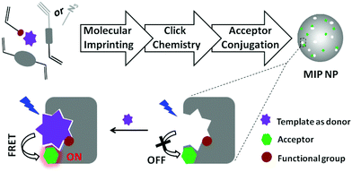
In this communication we describe a new modular approach for synthesizing fluorescent MIP nanoparticles. The MIP nanoparticles are designed to enable turn-on fluorescence assays using FRET as the signal transduction mechanism (Scheme 1). The synthetic approach is composed of three independent steps: first, precipitation polymerization is used to synthesize clickable MIP nanoparticles containing orthogonal alkyne or azide groups. In the second step, the alkyne or azide groups located in the MIP nanoparticles are click-conjugated to an azide- or alkyne-tagged organic amine through a Cu(I)-catalyzed 1,3-dipolar cycloaddition reaction (click chemistry). In the last step, the modified MIP nanoparticles are reacted with an amine-reactive fluorescent dye to furnish the final fluorescent MIP nanoparticles. The amine-reactive fluorescent dye is selected such that it can offer effective fluorescence energy transfer with the analytical target. The proposed modular approach has several important advantages: as the molecular imprinting step does not involve interfering reagents, an optimal imprinting effect can be expected. Since the subsequent derivatization reactions are non-destructive for the pre-formed recognition sites, it is possible to retain the favourable molecular recognition selectivity in the final fluorescent MIP nanoparticles. At last, a wide variety of amine-reactive fluorescent dyes are commercially available, which makes it easy to design the fluorescent MIP nanoparticles for FRET assays of different analytical targets, being themselves fluorescent, or easy to be labelled with a suitable fluorescence donor or acceptor.
 | ||
| Scheme 1 Synthesis of fluorescent MIP nanoparticles (NPs) for turn-on fluorescence assay based on FRET. | ||
In this work, we used a therapeutic drug, propranolol, as a model to study the feasibility of our synthetic design. Propranolol itself is a fluorescent molecule and can be used as a fluorescence donor. The emission band of propranolol overlaps with the excitation band of dansyl chloride (DSC) that can be conjugated to amine-functionalized MIP nanoparticles. Based on these considerations, we choose to use DSC as the amine-reactive probe, and used the three-step reaction process as shown in Fig. S1 (ESI†) to synthesize propranolol-imprinted, dansyl-labelled fluorescent nanoparticles.
In the first step, propranolol-imprinted polymer nanoparticles containing alkyne groups (MIP-CCH) were synthesized by precipitation polymerization.18 These clickable MIP nanoparticles were then modified through Cu(I)-catalyzed click reaction to give amine-functionalized nanoparticles (MIP-NH2),19 which were reacted with dansyl chloride in the last step to furnish the fluorescent MIP nanoparticles (MIP-DSC). For comparison, non-imprinted polymer (NIP) nanoparticles were synthesized using the same procedure except for omission of propranolol in the first step reaction.
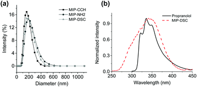
According to the SEM images in Fig. S1 (ESI†), the three MIP nanoparticles MIP-CCH, MIP-NH2 and MIP-DSC have a similar spherical shape and particle size. When the particle size was measured by dynamic light scattering (DLS), the hydrodynamic diameter of the particles MIP-CCH, MIP-NH2 and MIP-DSC were found to be 158 nm, 209 nm and 176 nm, respectively (Fig. 1a). The fact that MIP-NH2 has the largest particle size is somewhat surprising, and may be explained as a result of stronger particle–particle interactions than the other two types of MIP nanoparticles under the experimental conditions. Indeed, the same phenomenon was observed for the three non-imprinted control polymers (Fig. S2, ESI†), where the average diameter of NIP-CCH, NIP-NH2 and NIP-DSC was determined to be 485 nm, 710 nm and 504 nm, respectively. The difference in particle size between each MIP and its corresponding NIP particles was due to the impact of the molecular template used during the imprinting reaction, as has been discussed in the previous literature.18–20
 | ||
| Fig. 1 (a) Hydrodynamic diameter of MIP nanoparticles measured by DLS; (b) fluorescence emission band of propranolol and an excitation band of DSC. | ||
As shown in Fig. 1b, the fluorescence emission band of propranolol overlaps with the excitation band of MIP-DSC, which is essential for establishing an effective FRET between the imprinted polymer and the target analyte after specific binding. In the literature it has been suggested that to get a high FRET efficiency, the fluorescence donor:acceptor ratio should be kept less than 1.21 Therefore, it is necessary to control the amount of the fluorescence acceptor introduced into the MIP nanoparticles. In this work, the amount of DSC incorporated into MIP-DSC and NIP-DSC was determined to be 0.19 mmol g−1 and 0.40 mmol g−1, respectively (Table S1, ESI†). Given that the number of specific binding sites in non-covalently imprinted polymers is normally less than 0.1 mmol g−1, the amount of DSC conjugated to the present polymer particles was considered appropriate for obtaining satisfactory fluorescence response.
For MIPs designed to act as chemical sensors, it is important that the MIPs have a high molecular imprinting effect, which can be evaluated by the measurement of the imprinting factor (IF). The IF value can be calculated as the ratio of the amount of template bound on an MIP versus on a corresponding NIP under the same conditions. As shown in Fig. S3 (ESI†), all the MIP nanoparticles prepared in the present work bound significantly higher amounts of propranolol than their corresponding NIP nanoparticles. The three MIP nanoparticles have the same IF value of 3.7 (Table S1, ESI†). This result indicates clearly that the template propranolol has indeed produced a high imprinting effect. Furthermore, our post-imprinting modification did not compromise the specific binding of propranolol to the imprinted particles.
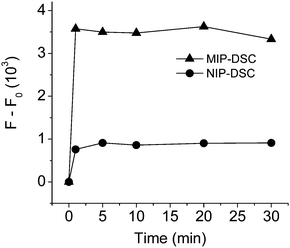
To examine if effective FRET can be realized between the bound propranolol and the fluorescence acceptor in MIP-DSC, we first designed a separation-free assay system by dispersing MIP-DSC in acetonitrile, and measured the fluorescence emission of DSC using the excitation band of propranolol. The fluorescence assay was carried out at different times after addition of propranolol. As shown in Fig. 2, it is clear that addition of propranolol caused the DSC emission to increase more significantly for the MIP-DSC system than for the NIP-DSC system. The increase of the fluorescence signal in the MIP-DSC system was about 4 times of the NIP-DSC system. Furthermore, the FRET signal became stable in less than 1 min, suggesting that propranolol binding to the nanoparticles has a very fast binding kinetics. To further confirm that the fast and higher fluorescence response observed in the MIP-DSC system was caused by specific propranolol binding, we also measured the kinetic propranolol binding to the different nanoparticles. The kinetic binding data, as shown in Fig. S4 (ESI†), produced an uptake-time response curve very similar to the fluorescence-time response curve shown in Fig. 2. Based on both the measurements, high specific binding and fluorescence response (FRET) were confirmed to be achieved with the imprinted nanoparticles within a very short time.
Analogous to the IF value used to evaluate the specific binding, a new parameter defined as the ratio of the FRET signal between the MIP-DSC system ((F − F0)MIP) and the NIP-DSC system ((F − F0)NIP) can be used to evaluate the specific fluorescence response of the nanoparticle sensors. According to the data in Fig. 2, the equilibrium value of (F − F0)MIP/(F − F0)NIP is calculated to be about 4, which is about the same as the IF value obtained from the binding data. This result suggests that the specific turn-on fluorescence emission in the MIP-DSC system was indeed caused by the specific propranolol binding.
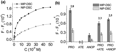
To investigate the relationship between propranolol concentration and the FRET signal generated in the MIP-DSC system, we studied the dose–response fluorescence emission of MIP-DSC caused by an increasing amount of propranolol. As shown in Fig. 3a, the FRET signal from the MIP-DSC system became stronger when an increasing amount of propranolol was added. Although the NIP-DSC system also exhibited a similar dose-responsive behaviour, the FRET signal from the MIP-DSC system was at least two times of that from the NIP-DSC system, which can be attributed to the specific propranolol binding to the imprinted particles. To further verify that the higher dose-responsive emission in the MIP-DSC system was caused by the specific propranolol binding, we also compared the uptake of propranolol by MIP-DSC with that by NIP-DSC particles in equilibrium binding experiments. As shown in Fig. S5 (ESI†), the equilibrium binding curves of propranolol with MIP-DSC and NIP-DSC are very similar to the fluorescence-concentration curves shown in Fig. 3a, indicating that the FRET signal is proportional to the amount of propranolol that specifically bound to the MIP-DSC nanoparticles. At high propranolol concentration, the specific binding sites became saturated, and consequently the FRET signal reached the maximal value. By comparing the parameters of (F − F0)MIP/(F − F0)NIP with the IF values (Fig. S6, ESI†), we obtained almost the same values at the same propranolol concentration. This result indicates that the specificity of the fluorescence MIP sensor is largely determined by the specific target binding to the imprinted nanoparticles.
The dose-responsive fluorescence emission data obtained from MIP-DSC (Fig. 3a) can be transferred to a linear calibration curve for non-separation assay of propranolol. As shown in Fig. S7 (ESI†), the linear range of the turn-on fluorescence assay based on FRET is 0.5–40 μM. As the turn-on fluorescence assay does not require any separation step, it has a fast response time and is much easier to use than the conventional methods that involve tedious separation and sample preparation steps.
The selectivity of the turn-on fluorescence assay was further studied by comparing the variation of fluorescence intensity of MIP-DSC caused by several propranolol analogues. In this study, atenolol (ATE) and 1-amino-3-(naphthalene-1-yloxy)propan-2-ol (ANOP) were selected as two representative analogues, because atenolol has the same critical functional groups as propranolol that determines the specific binding but is not fluorescent, while ANOP has the same fluorescence spectra as propranolol but lacks the important functional groups to ensure effective binding to propranolol-imprinted polymers (Fig. S8, ESI†).22 As shown in Fig. 3b, after addition of atenolol, the FRET signal induced by propranolol from MIP-DSC decreased, which is as expected because the added atenolol displaced a portion of the previously bound propranolol in the MIP-DSC particles, leading to a reduction of the FRET signal. Nevertheless, the relatively small reduction in the FRET signal suggests that the imprinted nanoparticle sensor maintains a high selectivity for propranolol. In the case of ANOP, the FRET signal was affected even less by the added ANOP, because ANOP, despite its strong fluorescence emission, did not bind to MIP-DSC and therefore was unable to influence the FRET signal caused by propranolol. The fact that ANOP did not bind to MIP-DSC is proven by that the mixture of ANOP and MIP-DSC gave very low emission at 500 nm when the mixture was exposed to the excitation band for ANOP. Based on the results from these competitive experiments, we can conclude that the turn-on fluorescence assay for propranolol has a high selectivity and is not easily affected by potential interfering compounds.
The applicability of the new separation-free, turn-on fluorescence assay based on MIP-DSC for real sample analysis was demonstrated by measuring propranolol in spiked tap water. In this case we first established a calibration curve for propranolol using a mixture of acetonitrile and pH 7 buffer as a solvent. When propranolol-spiked tap water was tested, the sample was simply mixed with acetonitrile containing the MIP-DSC nanoparticles, followed by direct measurement of the fluorescence emission at 500 nm. From Fig. S9 (ESI†), it is clear that the FRET signal in response to propranolol in the acetonitrile-buffer solvent is similar to that obtained in pure acetonitrile (Fig. 3a). When a tap water sample spiked with 20 μM propranolol was tested, the concentration of propranolol was found to be 19 ± 7 μM using the turn-on fluorescence assay, which is in good agreement with the theoretical value.
In this communication we have described a new strategy to develop turn-on fluorescence sensors using molecularly imprinted nanoparticles. This strategy uses non-destructive post-imprinting modification to introduce into MIP nanoparticles a suitable fluorescence acceptor that can form effective FRET with a predetermined fluorescent analyte. The synthetic strategy can also be used to develop turn-on fluorescence sensors for non-fluorescent analytes as long as a fluorescent probe can be used (i.e. as a target analogue) to report the specific molecular binding event. The synthetic strategy was demonstrated successfully by using propranolol as a model template and a fluorescence donor, and dansyl amide as a fluorescence acceptor to establish the required FRET system. The turn-on fluorescence assay for propranolol has several advantages including not requiring any separation steps, very short response time and high selectivity. The results reported here should open a new avenue for the design of turn-on fluorescence assay platforms based on MIPs. The target analytes are not limited to small organic molecules but may be expanded also to cover important biomacromolecules, for example different protein biomarkers. In addition, the lack of separation and fast response time of similar MIP-based FRET platforms should have a high potential for bio-imaging applications.
This work was supported by the Swedish research council FORMAS (grant no. 212-2013-1350).
References
- T. Förster, Ann. Phys., 1948, 2, 55 CrossRef.
- E. A. Jares-Erijman and T. M. Jovin, Nat. Biotechnol., 2003, 21, 1387 CrossRef CAS PubMed.
- (a) L. Stryer and R. P. Haugland, Proc. Natl. Acad. Sci. U. S. A., 1967, 58, 719 CrossRef CAS PubMed; (b) T. Ha, T. Enderle, D. F. Ogletree, D. S. Chemla, P. R. Selvin and S. Weiss, Proc. Natl. Acad. Sci. U. S. A., 1996, 93, 6264 CrossRef CAS PubMed.
- H. Q. Peng, L. Y. Niu, Y. Z. Chen, L. Z. Wu, C. H. Tung and Q. Z. Yang, Chem. Rev., 2015, 115, 7502 CrossRef CAS PubMed.
- (a) K. E. Sapsford, L. Berti and I. L. Medintz, Angew. Chem., Int. Ed., 2006, 45, 4562 CrossRef CAS PubMed; (b) J. Y. Shi, F. Tian, J. Lyu and M. Yang, J. Mater. Chem. B, 2015, 3, 6989 RSC.
- A. Bradbury and A. Pluckthun, Nature, 2015, 518, 27 CrossRef CAS PubMed.
- (a) G. Wulff and A. Sarhan, Angew. Chem., Int. Ed., 1972, 11, 341 CAS; (b) G. Vlatakis, L. I. Andersson, R. Muller and K. Mosbach, Nature, 1993, 361, 645 CrossRef CAS PubMed.
- (a) G. Wulff, Chem. Rev., 2002, 102, 1 CrossRef CAS PubMed; (b) L. Ye and K. Haupt, Anal. Bioanal. Chem., 2004, 378, 1887 CrossRef CAS PubMed.
- (a) M. J. Whitcombe, I. Chianella, L. Larcombe, S. A. Piletsky, J. Noble, R. Porter and A. Horgan, Chem. Soc. Rev., 2011, 40, 1547 RSC; (b) R. Schirhagl, Anal. Chem., 2014, 86, 250 CrossRef CAS PubMed; (c) L. Chen, X. Wang, W. Lu, X. Wu and J. Li, Chem. Soc. Rev., 2016, 45, 2137 RSC.
- (a) P. Turkewitsch, B. Wandelt, G. D. Darling and W. S. Powell, Anal. Chem., 1998, 70, 2025 CrossRef CAS; (b) P. Manesiotis, A. J. Hall and B. Sellergren, J. Org. Chem., 2005, 70, 2729 CrossRef CAS PubMed; (c) J. K. Awino and Y. Zhao, Chem. Commun., 2014, 50, 5752 RSC.
- (a) Y. Suga, H. Sunayama, T. Ooya and T. Takeuchi, Chem. Commun., 2013, 49, 8450 RSC; (b) H. Sunayama, T. Ooya and T. Takeuchi, Chem. Commun., 2014, 50, 1347 RSC.
- (a) C. Sulitzky, B. Ruckert, A. J. Hall, F. Lanza, K. Unger and B. Sellergren, Macromolecules, 2002, 35, 3314 CrossRef CAS; (b) Y. Mao, Y. Bao, D. X. Han, F. H. Li and L. Niu, Biosens. Bioelectron., 2012, 38, 55 CrossRef CAS PubMed.
- S. F. Xu and H. Z. Lu, Chem. Commun., 2015, 51, 3200 RSC.
- H. L. Liu, G. Z. Fang, H. D. Zhu, C. M. Li, C. C. Liu and S. Wang, Biosens. Bioelectron., 2013, 47, 127 CrossRef CAS PubMed.
- S. Beyazit, S. Ambrosini, N. Marchyk, E. Palo, V. Kale, T. Soukka, B. T. S. Bui and K. Haupt, Angew. Chem., Int. Ed., 2014, 53, 8919 CrossRef CAS PubMed.
- (a) L. J. Fan and W. E. Jones, J. Am. Chem. Soc., 2006, 128, 6784 CrossRef CAS PubMed; (b) S. T. Huang, Y. Shi, N. B. Li and H. Q. Luo, Chem. Commun., 2012, 48, 747 RSC.
- (a) A. B. Descalzo, C. Somoza, M. C. Moreno-Bondi and G. Orellana, Anal. Chem., 2013, 85, 5316 CrossRef CAS PubMed; (b) S. H. Li, J. H. Luo, G. H. Yin, Z. Xu, Y. Le, X. F. Wu, N. C. Wu and Q. Zhang, Sens. Actuators, B, 2015, 206, 14 CrossRef CAS.
- K. Yoshimatsu, K. Reimhult, A. Krozer, K. Mosbach, K. Sode and L. Ye, Anal. Chim. Acta, 2007, 584, 112 CrossRef CAS PubMed.
- C. G. Xu and L. Ye, Chem. Commun., 2011, 47, 6096 RSC.
- (a) Y. Y. Long, J. Y. N. Philip, K. Schillen, F. Liu and L. Ye, J. Mol. Recognit., 2011, 24, 619 CrossRef CAS PubMed; (b) X. T. Shen and L. Ye, Macromolecules, 2011, 44, 5631 CrossRef CAS PubMed; (c) A. Poma, A. Guerreiro, M. J. Whitcombe, E. V. Piletska, A. P. F. Turner and S. A. Piletsky, Adv. Funct. Mater., 2013, 23, 2821 CrossRef CAS PubMed.
- K. Furukawa, H. Nakashirna, Y. Kashimura and K. Torimitsu, Langmuir, 2008, 24, 921 CrossRef CAS PubMed.
- B. Malm, K. Yoshimatsu, L. Ye and A. Krozer, J. Mol. Recognit., 2014, 27, 714 CrossRef CAS PubMed.
Footnote |
| † Electronic supplementary information (ESI) available. See DOI: 10.1039/c6cc06628c |
| This journal is © The Royal Society of Chemistry 2016 |


