
 Open Access Article
 This Open Access Article is licensed under a Creative Commons Attribution-Non Commercial 3.0 Unported Licence
An innovative in situ AFM system for a soft X-ray spectromicroscopy synchrotron beamline
Aljoša
Hafner
 a,
Luca
Costa
b,
George
Kourousias
a,
Valentina
Bonanni
a,
Milan
Žižić
a,
Andrea
Stolfa
a,
Benjamin
Bazi
c,
Laszlo
Vincze
c and
Alessandra
Gianoncelli
*a
a,
Luca
Costa
b,
George
Kourousias
a,
Valentina
Bonanni
a,
Milan
Žižić
a,
Andrea
Stolfa
a,
Benjamin
Bazi
c,
Laszlo
Vincze
c and
Alessandra
Gianoncelli
*a
aElettra Sincrotrone Trieste, SS 14 km 163, 5 in Area Science Park, 34149 Basovizza, Trieste, Italy. E-mail: alessandra.gianoncelli@elettra.eu
bCentre de Biochimie Structurale, CNRS UMR 5048 - UM - INSERM U 1054, 29 rue de Navacelles 34090 Montpellier, France
cDepartment of Chemistry, Ghent University, Krijgslaan 281, B-9000 Ghent, Belgium
First published on 23rd November 2023
Abstract
Multimodal imaging and spectroscopy like concurrent scanning transmission X-ray microscopy (STXM) and X-ray fluorescence (XRF) are highly desirable as they allow retrieving complementary information. This paper reports on the design, development, integration and field testing of a novel in situ atomic force microscopy (AFM) instrument for operation under high vacuum in a synchrotron soft X-ray microscopy STXM–XRF end-station. A combination of μXRF and AFM is demonstrated for the first time in the soft X-ray regime, with an outlook for the full XRF–STXM–AFM combination.
Introduction
Since the invention of scanning probe microscopes (SPMs),1,2 several correlative SPM–optical techniques have been proposed and reported in the literature. Atomic force microscopy (AFM) was used in its early years with visible or near-infrared light to overcome the diffraction limit and obtain super-resolved optical images.3 In contrast, the first SPM–X-ray correlative setups have been conceived only at a second stage. Synchrotron beamlines, where X-rays are generally employed, particularly due to their associated dimensions and geometry, require the design of dedicated SPM instruments which can be rarely replaced by commercial microscopes. Scanning tunnelling microscopes (STMs) and X-rays are nowadays largely employed at the Advanced Photon Source (APS), where the X-ray beam can be used to tune the tunnelling current measured by STM4 or eventually the STM tip can be employed to locally supply electrical energy.5 Regarding AFM, it provides topographical and mechanical information of the sample, which cannot be directly obtained with X-ray techniques. The latter can be used to assess chemical information usually not obtainable by AFM. Therefore, the combination of two techniques in a single instrument takes advantage of both capabilities. The first AFM built for a synchrotron beamline (X-AFM) was designed in the late 2000s by the Surface Science Laboratory at the European Synchrotron Radiation Facility (ESRF).6,7 The authors reported several acquisition schemes where the AFM tip could be employed as a local detector for the diffracted X-ray beams or, alternatively, as a detector for total electron yield experiments. Additionally, they show how the diffraction pattern could be directly related to the force applied by the AFM tip during an indentation experiment.7 In parallel, several beamlines in Europe started to develop their own X-AFMs. At the Swiss Light Source (SLS) the whole nanoXAS beamline was built to integrate an AFM for normal incidence X-ray experiments such as scanning transmission X-ray microscopy (STXM), delivering impressive and highly resolved results.8 At the Deutsches Elektronen-Synchrotron (DESY), a commercial AFM was installed at the P01 beamline to combine AFM and Raman spectroscopy using synchrotron light,9 whereas a second AFM was installed at the P10 beamline and correlated to grazing incidence X-ray diffraction (GIXD) and grazing incidence X-ray scattering (GISAXS).10 Finally, at the ESRF two additional X-AFMs were introduced.11 The first one was installed at the ID03 beamline, where the X-ray reflectivity (XRR) and GIXD of supported lipid bilayers in liquid solution were correlated to the mechanics and morphology imaged by AFM,12 opening the way to X-AFM studies performed in liquid in a physiological and bio-friendly environment. The second one was installed at the ID13 beamline (ESRF), in a normal incidence configuration, and is compatible with the use of a sub-micrometric X-ray beam.13Here we report a novel prototype of X-AFM compatible with a soft X-ray beamline in a normal incidence working scheme and operating inside a high vacuum chamber. In this frame, our instrument is partially similar to the setup installed at the nanoXAS beamline at SLS.8 However, in our case, the AFM tip is positioned upstream of the sample, in between the last optical element and the sample (Fig. 1). This provides advantages since the AFM does not replace the CCD used for normal operation, as in the nanoXAS case, but presents several geometrical challenges. Additionally, our microscope is able to simultaneously acquire XRF and AFM maps. While this manuscript reports a successful AFM–XRF correlation, in perspective, our setup can be easily applied to the AFM–STXM integration, especially in the soft X-ray frame. It is worth noting that the combination of AFM and XRF in the hard X-ray regime, which means in an air environment, is much easier to implement and less compelling.14
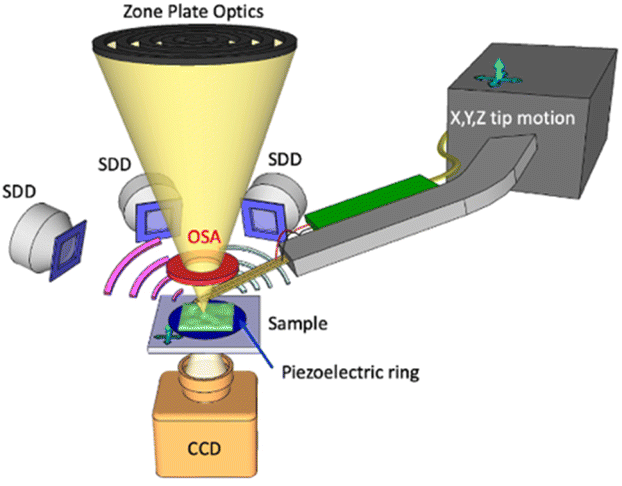 | ||
| Fig. 1 Combined AFM, XRF and STXM in a single instrument. Sketch of the developed system as deployed at the TwinMic beamline. The monochromatised X-ray beam is incident perpendicularly on the sample plane and is focused through a zone plate diffractive optics while the order sorting aperture (OSA) selects the first diffraction order. The sample is scanned in the X and Y directions on the TwinMic sample stage and the transmitted X-rays are collected using a CCD camera through an X-ray–visible light converting system (not shown here for simplicity). Low-energy X-ray fluorescence (LEXRF) is collected by up to 8 silicon drift detectors (SDDs) in a backscattered configuration. The AFM tip is controlled by an X, Y, Z motor stage. | ||
Soft X-ray microscopy is indeed becoming a more and more widespread analytical tool for investigating complex systems at the micrometric and sub-micrometric levels, especially when combined with X-ray spectroscopy capabilities.15 Several synchrotrons worldwide have installed STXM beamlines,16–25 similar to each other but at the same time each with unique capabilities. STXM is a scanning technique where the sample is usually raster-scanned across a micro- or nano-probe by photons delivered by suitable X-ray optics (Fig. 1). During the scans, transmitted X-rays are collected by a monodimensional detector such as a photodiode or a photomultiplier tube, or by a two-dimensional detector such as the fast readout CCD camera used at TwinMic beamline,20 yielding absorption and, in the latter case, possibly differential phase contrast images.26 Simultaneously other signals, such as emitted photoelectrons or emitted XRF photons, can be collected at X-ray photoelectron spectroscopy stations. The TwinMic beamline20 at Elettra Sincrotrone Trieste (Trieste, Italy), which combines STXM in the 400–2200 eV energy range with low energy XRF (LEXRF) microscopy,27,28 has attracted the interest of several scientific communities worldwide.29–37
Since its first design and initial project, the TwinMic microscope has been conceived as a multi-modal/multi-technique instrument,27,38,39 where for instance, STXM could be combined with full-field microscopy. In this paper, we focus on AFM integration within the existing TwinMic microscope. We present the advantages of the setup and report preliminary AFM and XRF maps acquired in situ, demonstrating the feasibility of such correlative acquisitions. Finally, we discuss future challenges and potential applications for both combined microscopy and spectroscopy.
The TwinMic microscope currently consists of two separate vacuum chambers, one of which hosts the soft X-ray focusing optics and the other one comprises the setup for collecting the transmitted X-rays. The sample compartment is a 5 cm wide space located in between the two chambers. The system is highly modular and tidy, as for instance the zone plate optics holder is a cylinder coaxially inserted in a wider cylinder holding the order sorting aperture (OSA) element. However, such a system suffers from mechanical constraints, as the available space around the sample is relatively small and limits the possibility of inserting new detector systems. Moreover, reducing the incident energy implies a shorter zone plate focal length and a smaller sample–OSA distance, further limiting accessibility to the area surrounding the sample. Nevertheless, a multi-SDD XRF system was successfully developed and installed a decade ago, paving the way for elemental mapping in the soft X-ray regime.27
Considering the worldwide success of the challenging LEXRF system and several studies specifically performed on TwinMic requiring AFM microscopy to be performed on the same analyzed samples,40,41 the idea of a new highly miniaturized vacuum compatible AFM system started to be conceived. However, as already pointed out, working with soft X-rays implies a focal length on the order of a few millimetres. All of this makes it challenging to insert further detector or inspection systems. Indeed, as previously mentioned, to overcome this issue, the soft X-ray AFM integrated at nanoXAS (SLS) was positioned downstream of the sample, replacing the X-ray detector normally used for STXM,8 and not in between the last optical element and the sample. In contrast, our AFM prototype has been custom designed to fit in the vacuum chamber and to position the AFM cantilever, its tip, the required electronics and the detection system within a thickness of 10 mm, available between the last optical focusing element and the sample surface, that is, upstream of the sample. In contrast to what was proposed at nanoXAS (SLS),8 our solution does not substantially perturb or change the STXM setup, as the STXM CCD detector is still in place and can collect the transmitted photons even when the AFM tip is inserted. A sketch is shown in Fig. 1 and a picture in Fig. 2a.
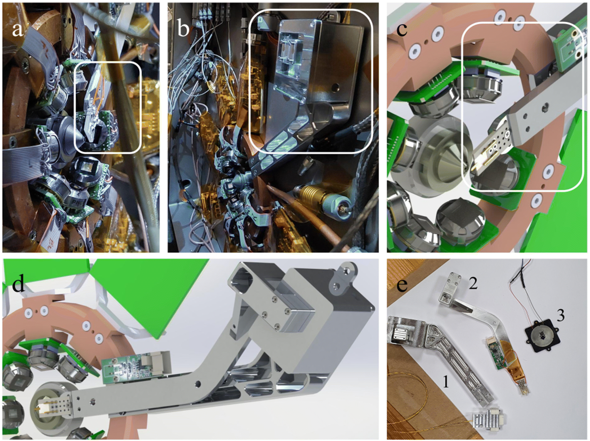 | ||
| Fig. 2 AFM system in the beamline chamber. Panels (a) and (b) show the AFM probe and its installed inertial motors, respectively, highlighted by the two white rectangles. CAD designs (c and d) with respect to the existing SDD XRF detection system. The white rectangle in panel (c) highlights the AFM tip plus the preamplifier system. Panel (e) shows the AFM components of the system installed inside the chamber; inertial motors (1), the probe support and preamp (2) and the piezo-adapted standard TwinMic sample holder (3). | ||
The developed AFM setup consists of an Akiyama probe42 as an AFM cantilever (Nanosensors). This self-sensing AFM probe does not necessitate any optical detection system such as optical beam deflection43 that would require the insertion of a laser source, a two or four quadrant detector and several micro-positioning devices that cannot fit within the few mm space available. The probe can be moved over 1 cm × 1 cm × 1 cm using three inertial motors (Mechonics MX.025) positioned inside the vacuum chamber (Fig. 2b). An 18.5 cm long arm is screwed at the top of the XYZ inertial motor stage (Fig. 2d) and is used to position the AFM tip into the beam focal point at the sample axial position. We fixed the Akiyama TFSC-PREAMP preamplifier (Nanosensors), disassembled in two parts, along the metallic arm (Fig. 2c). The scanner consists of (i) the TwinMic piezoelectric scanner for X and Y displacement (Physics Instrument), already present on the sample stage, allowing for a scan range of 80 μm × 80 μm, and (ii) a newly installed PD150.31 piezoelectric ring (Physics Instrument) for the Z (axial) movement (Fig. 1). The use of a ring allows for X-ray transmission over a large solid angle and could be easily integrated in the TwinMic standard sample holder (Fig. 2e, object 3). The excitation of the AFM probe and the detection of the associated oscillation amplitude and phase are performed using a SR830 lock-in amplifier (Stanford Research).
The proportional-integrative control for AFM operation and a custom phase-locked loop (PLL) interacting with SR830 were built in a Labview program (NI) driving a USB-6341 (NI) I/O card. Indeed, since X-ray experiments are performed in a high vacuum, the Q factor of the AFM probe is high and requires the use of frequency modulation AFM mode44 for image acquisition at a constant frequency shift, which in turn necessitates the use of a PLL to keep the phase of the AFM probe constant.
Once the AFM probe (Fig. 3a) is placed inside the vacuum chamber, it can be aligned with the X-ray optics using the STXM CCD camera, as shown in Fig. 3b, by moving the OSA out of the beam (Fig. 3b) and observing the transmission projection of the probe in front of the Fresnel zone plate and the OSA (Fig. 3b). We expect that by measuring the current flow within the AFM tip it would be possible to refine the alignment in the future, as reported previously.6 This can be performed by using inertial motors to scan the tip with respect to the fixed X-ray beam. Subsequently, by using one inertial motor, the tip is approached axially to the sample by monitoring the cantilever frequency shift. The PI controller drives the piezoelectric ring, here the Z scanner, to keep a constant frequency shift of −50 Hz, representing an attractive force gradient setpoint. Once the setpoint is reached and kept constant, the approach is stopped and the tip–sample distance is controlled by the piezoelectric ring only. The AFM tip–sample approach is performed in a vacuum environment to prevent variations in the tip–sample distance that typically occur during degassing, usually leading to tip and sample damage. At this stage, correlative and multimodal XRF–AFM can start.
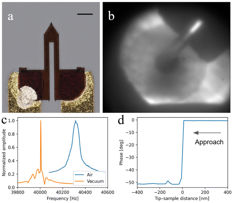 | ||
| Fig. 3 AFM tuning fork and cantilever. Visible light image (a) with 100 μm scale bar. X-ray TX projection (b) showing the tip in front of the zone plate optics and the central stop. Normalized resonance sweep in air (blue) and under vacuum (orange) (c), showing the expected increase of the Q factor under vacuum. Tip sample approach curve (d) showing a sudden decrease of the phase at the tip–sample mechanical contact point, indicating a rapid shift of the resonance. | ||
High vacuum affects the mechanical resonance of the AFM cantilever by consistently increasing the Q-factor compared to ambient conditions. Fig. 3c shows a comparison between the resonance under ambient (Q factor = ω/Δω ≈ 850) and vacuum (Q factor ≈ 40![[thin space (1/6-em)]](https://www.rsc.org/images/entities/char_2009.gif) 000) conditions as measured by a lock-in frequency sweep. As previously mentioned, such a high Q-factor has important consequences on AFM operation: as soon as the tip approaches the sample, the oscillation amplitude drops to zero while the phase experiences a sudden shift higher than 50 degrees (Fig. 3d). This is likely due to the shift of the resonance frequency: because of the high Q-factor, a frequency shift of even 1 Hz would provoke such a drastic phase shift, resulting in the impossibility to perform amplitude modulation AFM (AM-AFM).45 For this reason, AFM images were acquired in frequency modulation mode (FM-AFM).
000) conditions as measured by a lock-in frequency sweep. As previously mentioned, such a high Q-factor has important consequences on AFM operation: as soon as the tip approaches the sample, the oscillation amplitude drops to zero while the phase experiences a sudden shift higher than 50 degrees (Fig. 3d). This is likely due to the shift of the resonance frequency: because of the high Q-factor, a frequency shift of even 1 Hz would provoke such a drastic phase shift, resulting in the impossibility to perform amplitude modulation AFM (AM-AFM).45 For this reason, AFM images were acquired in frequency modulation mode (FM-AFM).
Images were acquired with 321 pixels × 321 lines at a line rate of 0.3 lines per s. Fig. 4 shows the AFM topographical image (a) and the associated aluminium (c) and silicon (d) XRF K-line maps acquired at 2 keV, all compared to the ex situ AFM map acquired a posteriori (b) with a JPK Nanowizard 4 (Bruker) commercial AFM. The measured sample is a test object created by depositing Al stripes on a 100 nm thick Si3N4 window. Despite the noise present in the AFM image, mostly due to the recurrent Z-scanner overflow which had to be occasionally corrected using the axial inertial motor, and visible in several horizontal lines over the image, the morphological contrast between the Al and Si layers gets more visible with the decrease of the frequency shift setpoint (down to ≈ −130 Hz), corresponding to an increase of the attractive force gradient and consequently to a closer tip–sample distance. Fig. 4 demonstrates that the correlative use of AFM and XRF is feasible and provides important complementary information about the sample.
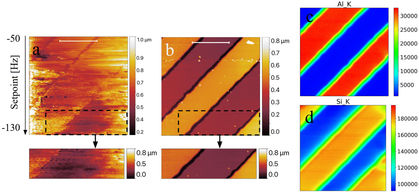 | ||
| Fig. 4 In situ AFM topography (scale bar is 30 μm) with the corresponding ROI (dashed box) (a), ex situ AFM topography (scale bar is 30 μm) with JPK Nanowizard 4 with the corresponding ROI (dashed box) (b), aluminium XRF K-line map (c) and silicon XRF K-line map (d) acquired at 2 keV concurrently with AFM (a). The sample consists of Al stripes deposited on a 100 nm thick Si3N4 window. All images were collected over an area of 80 × 80 μm2, with a step size of 250 nm and a beam diameter size of 280 nm. The black arrow indicates the setpoint decrease during image acquisition to enhance morphological variations. The units in the XRF maps are expressed in counts. | ||
While XRF can clearly identify the sample regions where Al and Si are present, AFM provides the associated layer thicknesses corresponding to ≈250 nm. The ex situ AFM image shown in Fig. 4b, acquired in quantitative imaging (QI) mode (ScanAsyst probes), has been used to accurately tune the calibration parameter ([nm V−1]) of the Z scanner within the TwinMic sample holder.
The presented results demonstrate for the first time the feasibility of combining AFM with in-vacuum XRF and STXM in a single instrument. For the moment, the AFM measurement has been combined with XRF acquisition only, but this can be easily extended to STXM as well.
Moreover, based on the size of the overall AFM system, the prototype allows a minimum distance of 1.2 mm between the sample and the OSA (the last optical element), thus permitting measurements also at much lower energy. With the current zone plate optics and OSA this could be performed down to 500 eV. Optimisation of both optical elements could allow even lower energies.
Based on the tests and the challenges faced during the measurements, several improvements are foreseen from several points of view, both from the electronic and the mechanical sides. At first, by chopping the X-ray beam at a tunable frequency (on the order of kHz), a low-noise measurement of the current flowing in the AFM probe will allow the development of an accurate probe–X-ray beam alignment, as previously mentioned. Then, the AFM probe can be used as an X-ray or electron sensor for local XRF and total yield spectroscopy. Mechanical improvements are mainly related to the long arm (Fig. 2d) acting as the cantilever holder, which will be shortened and equipped with custom damping in the frame of the end-station upgrade that is foreseen for the TwinMic microscope: with the Elettra Synchrotron Upgrade program, namely Elettra 2.0,46 the two-chamber setup will indeed be replaced with a single one. This will allow access to the sample from almost all sides and thus permit the insertion and retraction of different detector systems, making the end-station more flexible and more suitable for implementing innovative imaging capabilities. It is expected that with the new TwinMic end-station, more focused instrumental choices can be made for further developing the AFM system in a more efficient way. In this frame, the integration of an optical beam deflection system to monitor the AFM probe oscillation amplitude will be beneficial, allowing for the use of a large variety of AFM cantilevers, suited for different applications involving either the use of local electric or magnetic interactions or requiring probes with different geometries and sizes to apply specific indentation cycles.
Conclusions
This short communication reports on the successful development of a proof-of-concept in-vacuum custom designed AFM setup. It is integrated in situ on a synchrotron multimodal beamline offering sub-micron XRF and STXM imaging using soft X-rays. In particular, we show here the correlative acquisition of XRF maps and AFM topography. The placement of the AFM tip upstream of the sample offers several advantages and does not interfere with the STXM signals. The AFM coupling with STXM and XRF allows providing further complementary information about the samples, as their topography can be retrieved and exploited for XRF quantification or simply for morphological evaluation (i.e. for radiation damage investigations). By keeping the TwinMic transmission detector operational, indentation experiments coupled to ptychography can also be performed. In addition to STXM, small angle scattering/diffraction could be coupled to indentation experiments, offering a plethora of characterization possibilities that are not discussed in this manuscript.Various limitations and setup characteristics are discussed, including concerns regarding high vacuum, limited space, nanometric movement, and electronics. The manuscript provides an outlook on future scientific applications of high importance in several scientific fields and outlines the forthcoming updates of the AFM system which is already the thinnest of its kind.
Author contributions
AH: conceptualization, investigation, methodology, project administration, supervision, writing – original draft, and writing – review & editing; LC: conceptualization, formal analysis, investigation, methodology, software, writing – original draft, and writing – review & editing; GK: conceptualization, formal analysis, data curation, investigation, methodology, writing – original draft, and writing – review & editing; VB: investigation, formal analysis, and writing – review & editing; MZ: investigation, formal analysis, and writing – review & editing; AS: methodology and writing – review & editing; BB: investigation and writing – review & editing, LV: conceptualization, supervision, writing – review & editing, and investigation; and AG: conceptualization, funding acquisition, investigation, methodology, project administration, resources, supervision, writing – original draft, and writing – review & editing.Conflicts of interest
There are no conflicts to declare.Acknowledgements
We acknowledge Elettra Sincrotrone Trieste for the provision of synchrotron radiation facilities under proposal number 20220255. L. C. acknowledges financial support from ANR-21-CE20-0032. The CBS is a member of the France-BioImaging (FBI), national infrastructure supported by the French National Research Agency (ANR-10-INBS-04-01). B. B. acknowledges financial support from the Ghent University Special Research Fund (UGent BOF).References
- G. Binnig, H. Rohrer, Ch. Gerber and E. Weibel, Phys. Rev. Lett., 1982, 49, 57–61 CrossRef.
- G. Binnig, C. F. Quate and Ch. Gerber, Phys. Rev. Lett., 1986, 56, 930–933 CrossRef PubMed.
- H. Heinzelmann and D. W. Pohl, Appl. Phys. A, 1994, 59, 89–101 CrossRef.
- V. Rose, J. W. Freeland and S. K. Streiffer, in Scanning Probe Microscopy of Functional Materials: Nanoscale Imaging and Spectroscopy, ed. S. V. Kalinin and A. Gruverman, Springer, New York, NY, 2011, pp. 405–431 Search PubMed.
- T. M. Ajayi, V. Singh, K. Z. Latt, S. Sarkar, X. Cheng, S. Premarathna, N. K. Dandu, S. Wang, F. Movahedifar, S. Wieghold, N. Shirato, V. Rose, L. A. Curtiss, A. T. Ngo, E. Masson and S. W. Hla, Nat. Commun., 2022, 13, 6305 CrossRef PubMed.
- M. S. Rodrigues, O. Dhez, S. L. Denmat, J. Chevrier, R. Felici and F. Comin, J. Instrum., 2008, 3, P12004 CrossRef.
- T. Scheler, M. Rodrigues, T. W. Cornelius, C. Mocuta, A. Malachias, R. Magalhães-Paniago, F. Comin, J. Chevrier and T. H. Metzger, Appl. Phys. Lett., 2009, 94, 023109 CrossRef.
- N. Pilet, J. Raabe, S. E. Stevenson, S. Romer, L. Bernard, C. R. McNeill, R. H. Fink, H. J. Hug and C. Quitmann, Nanotechnology, 2012, 23, 475708 CrossRef PubMed.
- S. Rackwitz, I. Faus, B. Lägel, J. Linden, J. Marx, E. Oesterschulze, K. Schlage, H.-C. Wille, S. Wolff, J. A. Wolny and V. Schünemann, Hyperfine Interact., 2014, 226, 667–671 CrossRef CAS.
- T. Slobodskyy, A. V. Zozulya, R. Tholapi, L. Liefeith, M. Fester, M. Sprung and W. Hansen, Rev. Sci. Instrum., 2015, 86, 065104 CrossRef CAS PubMed.
- L. Costa and M. S. Rodrigues, Synchrotron Radiat. News., 2016, 29, 3–7 CrossRef.
- B. Gumí-Audenis, F. Carlà, M. V. Vitorino, A. Panzarella, L. Porcar, M. Boilot, S. Guerber, P. Bernard, M. S. Rodrigues, F. Sanz, M. I. Giannotti and L. Costa, J. Synchrotron Radiat., 2015, 22, 1364–1371 CrossRef PubMed.
- M. V. Vitorino, Y. Fuchs, T. Dane, M. S. Rodrigues, M. Rosenthal, A. Panzarella, P. Bernard, O. Hignette, L. Dupuy, M. Burghammer and L. Costa, J. Synchrotron Radiat., 2016, 23, 1110–1117 CrossRef CAS.
- K. Tsuji, T. Emoto, Y. Matsuoka, Y. Miyatake, T. Nagamura and X. Ding, Powder Diffr., 2005, 20, 137–140 CrossRef CAS.
- B. Kaulich, P. Thibault, A. Gianoncelli and M. Kiskinova, J. Phys.: Condens.Matter, 2011, 23, 083002 CrossRef PubMed.
- U. Wiesemann, J. Thieme, R. Früke, P. Guttmann, B. Niemann, D. Rudolph and G. Schmahl, Nucl. Instrum. Methods Phys. Res., Sect. A, 2001, 467–468, 861–863 CrossRef CAS.
- J. Schwenke, K. Thanell, I. Beinik, L. Roslund and T. Tyliszczak, Microsc. Microanal., 2018, 24, 232–233 CrossRef.
- H. Bluhm, K. Andersson, T. Araki, K. Benzerara, G. E. Brown, J. J. Dynes, S. Ghosal, M. K. Gilles, H.-Ch. Hansen, J. C. Hemminger, A. P. Hitchcock, G. Ketteler, A. L. D. Kilcoyne, E. Kneedler, J. R. Lawrence, G. G. Leppard, J. Majzlam, B. S. Mun, S. C. B. Myneni, A. Nilsson, H. Ogasawara, D. F. Ogletree, K. Pecher, M. Salmeron, D. K. Shuh, B. Tonner, T. Tyliszczak, T. Warwick and T. H. Yoon, J. Electron Spectrosc. Relat. Phenom., 2006, 150, 86–104 CrossRef CAS.
- B. Watts, S. Finizio, K. Witte, M. Langer, S. Mayr, S. Wintz, B. Sarafimov and J. Raabe, Microsc. Microanal., 2018, 24, 476–477 CrossRef.
- A. Gianoncelli, G. Kourousias, L. Merolle, M. Altissimo and A. Bianco, J. Synchrotron Radiat., 2016, 23, 1526–1537 CrossRef PubMed.
- H. J. Shin, N. Kim, H. S. Kim, W. W. Lee, C. S. Lee and B. Kim, J. Synchrotron Radiat., 2018, 25, 878–884 CrossRef CAS PubMed.
- J. Everett, F. Lermyte, J. Brooks, V. Tjendana-Tjhin, G. Plascencia-Villa, I. Hands-Portman, J. M. Donnelly, K. Billimoria, G. Perry, X. Zhu, P. J. Sadler, P. B. O'Connor, J. F. Collingwood and N. D. Telling, Sci. Adv., 2021, 7, eabf6707 CrossRef CAS PubMed.
- D. A. Santos, J. L. Andrews, B. Lin, L. R. De Jesus, Y. Luo, S. Pas, M. A. Gross, L. Carillo, P. Stein, Y. Ding, B.-X. Xu and S. Banerjee, Patterns, 2022, 3, 100634 CrossRef PubMed.
- H. Laval, A. Holmes, M. A. Marcus, B. Watts, G. Bonfante, M. Schmutz, E. Deniau, R. Szymanski, C. Lartigau-Dagron, X. Xu, J. M. Cairney, K. Hirakawa, F. Awai, T. Kubo, G. Wantz, A. Bousquet, N. P. Holmes and S. Chambon, Adv. Energy Mater., 2023, 13, 2300249 CrossRef.
- V. Bonanni and A. Gianoncelli, Int. J. Mol. Sci., 2023, 24, 3220 CrossRef PubMed.
- A. Gianoncelli, G. R. Morrison, B. Kaulich, D. Bacescu and J. Kovac, Appl. Phys. Lett., 2006, 89, 251117 CrossRef.
- A. Gianoncelli, B. Kaulich, R. Alberti, T. Klatka, A. Longoni, A. De Marco, A. Marcello and M. Kiskinova, Nucl. Instrum. Methods Phys. Res., Sect. A, 2009, 608, 195–198 CrossRef.
- A. Gianoncelli, G. Kourousias, A. Stolfa and B. Kaulich, J. Phys.: Conf. Ser., 2013, 425, 182001 CrossRef.
- L. Pascolo, A. Gianoncelli, G. Schneider, M. Salomé, M. Schneider, C. Calligaro, M. Kiskinova, M. Melato and C. Rizzardi, Sci. Rep., 2013, 3, 1123 CrossRef PubMed.
- C. Poitry-Yamate, A. Gianoncelli, B. Kaulich, G. Kourousias, A. W. Magill, M. Lepore, V. Gajdosik and R. Gruetter, J. Neurosci. Res., 2013, 91, 1050–1058 CrossRef CAS PubMed.
- B. Bozzini, P. Bocchetta, A. Gianoncelli, C. Mele and M. Kiskinova, ChemElectroChem, 2015, 2, 1541–1550 CrossRef CAS.
- F. Werner, C. W. Mueller, J. Thieme, A. Gianoncelli, C. Rivard, C. Höschen and J. Prietzel, Sci. Rep., 2017, 7, 3203 CrossRef PubMed.
- M. W. M. Jones, B. Abbey, A. Gianoncelli, E. Balaur, C. Millet, M. B. Luu, H. D. Coughlan, A. J. Carroll, A. G. Peele, L. Tilley and G. A. van Riessen, Opt. Express, 2013, 21, 32151–32159 CrossRef CAS PubMed.
- P. M. Kopittke, K. L. Moore, E. Lombi, A. Gianoncelli, B. J. Ferguson, F. P. C. Blamey, N. W. Menzies, T. M. Nicholson, B. A. McKenna, P. Wang, P. M. Gresshoff, G. Kourousias, R. I. Webb, K. Green and A. Tollenaere, Plant Physiol., 2015, 167, 1402–1411 CrossRef CAS PubMed.
- G. C. Vásquez, M. A. Peche-Herrero, D. Maestre, A. Gianoncelli, J. Ramírez-Castellanos, A. Cremades, J. M. González-Calbet and J. Piqueras, J. Phys. Chem. C, 2015, 119, 11965–11974 CrossRef.
- K. Klančnik, K. Vogel-Mikuš, M. Kelemen, P. Vavpetič, P. Pelicon, P. Kump, D. Jezeršek, A. Gianoncelli and A. Gaberščik, J. Photochem. Photobiol., B, 2014, 140, 276–285 CrossRef PubMed.
- S. Raneri, A. Giannoncelli, E. Mascha, L. Toniolo, M. Roveri, A. Lazzeri, M. B. Coltelli, L. Panariello, M. Lezzerini and J. Weber, Mater. Charact., 2019, 156, 109853 CrossRef CAS.
- B. Kaulich, D. Bacescu, J. Susini, C. David, E. Di Fabrizio, G. R. Morrison, P. Charalambous, J. Thieme, T. Wilhein, J. Kovac, D. Cocco, M. Salomé, O. Dhez, T. Weitkamp, S. Cabrini, D. Cojoc, A. Gianoncelli, U. Vogt, M. Podnar, M. Zangrando, M. Zacchigna and M. Kiskinova, Conf. Proc. Series IPAP 7, 2006, 7, 22–25.
- B. Kaulich, A. Gianoncelli, A. Beran, D. Eichert, I. Kreft, P. Pongrac, M. Regvar, K. Vogel-Mikuš and M. Kiskinova, J. R. Soc., Interface, 2009, 6, S641–S647 CrossRef CAS PubMed.
- A. Gianoncelli, L. Vaccari, G. Kourousias, D. Cassese, D. E. Bedolla, S. Kenig, P. Storici, M. Lazzarino and M. Kiskinova, Sci. Rep., 2015, 5, 10250 CrossRef CAS PubMed.
- E. Malucelli, S. Iotti, A. Gianoncelli, M. Fratini, L. Merolle, A. Notargiacomo, C. Marraccini, A. Sargenti, C. Cappadone, G. Farruggia, I. Bukreeva, M. Lombardo, C. Trombini, J. A. Maier and S. Lagomarsino, Anal. Chem., 2014, 86, 5108–5115 CrossRef CAS.
- T. Akiyama, N. F. de Rooij, U. Staufer, M. Detterbeck, D. Braendlin, S. Waldmeier and M. Scheidiger, Rev. Sci. Instrum., 2010, 81, 063706 CrossRef PubMed.
- G. Meyer and N. M. Amer, Appl. Phys. Lett., 1988, 53, 1045–1047 CrossRef.
- T. R. Albrecht, P. Grütter, D. Horne and D. Rugar, J. Appl. Phys., 1991, 69, 668–673 CrossRef.
- R. Garcia, Amplitude Modulation Atomic Force Microscopy, John Wiley & Sons, Ltd, 2010, pp. 59–76 Search PubMed.
- A. Franciosi and M. Kiskinova, Eur. Phys. J. Plus, 2023, 138, 79 CrossRef PubMed.
| This journal is © The Royal Society of Chemistry 2024 |