 Open Access Article
Edible mechanical metamaterials with designed fracture for mouthfeel control
André
Souto
a,
Jian
Zhang
 b,
Alejandro M.
Aragón
 *b,
Krassimir P.
Velikov
 *acd and
Corentin
Coulais
 *a
*a
aInstitute of Physics, University of Amsterdam, 1098 XH Amsterdam, The Netherlands. E-mail: Krassimir.Velikov@unilever.com; coulais@uva.nl
bFaculty of Mechanical, Maritime and Materials Engineering, Delft University of Technology, Mekelweg 2, 2628 CD Delft, The Netherlands. E-mail: a.m.aragon@tudelft.nl
cUnilever Innovation Centre Wageningen, 6708 WH Wageningen, The Netherlands
dDebye Institute for NanoMaterials Science, Utrecht University, 3584 CC, Utrecht, The Netherlands
First published on 21st March 2022
Abstract
Metamaterials can display unusual and superior properties that come from their carefully designed structure rather than their composition. Metamaterials have permeated large swatches of science, including electromagnetics and mechanics. Although metamaterials hold the promise for realizing technological advances, their potential to enhance interactions between humans and materials has largely remained unexplored. Here, we devise a class edible mechanical metamaterials with tailored fracture properties to control mouthfeel sensory experience. Using chocolate as a model material, we first demonstrate how to create and control the fracture anisotropy, and the number of cracks, and demonstrate that these properties are captured in mouthfeel experience. We further use topology optimization to rationally design edible metamaterials with maximally anisotropic fracture strength. Our work opens avenues for the use of metamaterials to control fracture and to enhance human-matter interactions.
Introduction
Mechanical metamaterials are man-made structures whose architecture provides unique and tunable properties.1–3 In particular, mechanical metamaterials have shown a wide variety of properties, from enhanced strength-to-weight ratio4 and dissipation,5 to programmable mechanical6 and shape-changing properties.7 A particularly interesting avenue for mechanical metamaterials is the design of tunable fracture and strength properties.4,8–10Tunable fracture properties have tantalizing prospects for engineering applications where strong and tough structures are much needed. However, little is known about how designed fracture could be used to enhance interactions between humans and materials. In particular, little is known about how to use tunable fracture to control mouthfeel and sensory experience upon biting.11 Controlling sensory experience is an important topic for the design of food products such as soups,12 yogurts,13 crackers,14 cookies,15 insects,16 as well as emulsions17 and protein-based17 food products. Although the role of mechanical contrast is generally recognized to influence mouthfeel18 and the use of 3d printing is emerging as a promising avenue to shape the texture of food products,19 the use of mechanical metamaterials for tunable mouthfeel has not being explored.
Here we demonstrate that suitably designed edible mechanical metamaterial with controllable fracture properties also have tunable mouthfeel. Namely, we use anisotropic structures to control the ease of bite and use spiral-shaped structures to control the perceived number of cracks. We further demonstrate that topology optimization allows the design of structures with anisotropic fracture properties. Our findings open avenues for design of mouthfeel using edible metamaterials and the topological design of fracture properties.
Results
Design of mouthfeel anisotropy
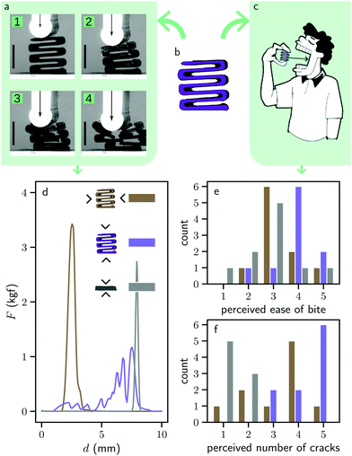
We start by a range of S-shaped mechanical metamaterials shown in Fig. 1b, which we test both mechanically (Fig. 1a) as well as with a sensory assessment (Fig. 1c). In the present study, we restrict our attention to chocolate as a model brittle material and we use 3D printing to prototype the desired architectures—see Methods for details on the design approach, the 3D printing, and the mechanical testing protocols. First, the mechanical compression tests reveal that each mechanical metamaterial has a very different fracture behavior depending on whether it is compressed along one axis or the other. When the structure is compressed along its horizontal direction, the structure is relatively stiff, strong, of comparable stiffness and strength to that of the reference geometry. It is also brittle, as the force-displacement curve exhibits a single peak. In contrast, when the structure is compressed along its vertical direction, the mechanical metamaterial is much softer, as its stiffness (strength) is 40 (25) times lower than in the horizontal direction (see Table II of the Methods). In addition, it is also less brittle, as the force-displacement curve exhibits a finite force for larger range of compressive displacements and multiple peaks. Thus, the mechanical metamaterials exhibits a strong anisotropic fracture response, which is difficult to realize in typical food microstructures.20To investigate whether this stark contrast in mechanical properties between the two orientations leads to a noticeable difference in perceived mouthfeel experience, we perform a sensory assessment on a batch of 10 persons—see Methods for details about the sensory assessment protocol. The results suggest that a noticeable difference in ease of bite is perceived between the two orientations of the mechanical metamaterial (Fig. 1e). A Fisher test for statistical relevance reveals that the mechanical metamaterial in the horizontal direction is systematically perceived as having an ease of bite lower than 3 whereas the mechanical metamaterial in the vertical direction is systematically perceived as having a ease of bite greater than or equal to 3—we find a significance level p = 3%. In contrast, a similar Fisher test reveals that both mechanical metamaterials have a comparable perceived number of cracks (Fig. 1f, we find a significance level of p = 9%, which exceeds the commonly used p = 5% threshold needed to claim statistical relevance21). To conclude, we observe a statistically significant correlation between the anisotropic strength of the mechanical metamaterials and the anisotropy in the ease of bite. An additional interesting feature is that the strong direction of the mechanical metamaterials has larger strength and comparable ease of bite than that of the reference, even though the volume density of the mechanical metamaterials is 64% (see Table II of the Methods), which is significantly lower than the 100% volume density of the reference structure.
Design of crack number
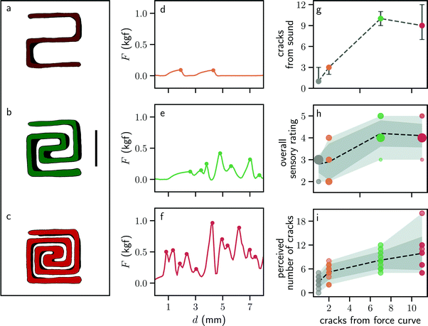
Which additional mouthfeel experiences can we tune with mechanical metamaterials? Inspired by the multiple local maxima of the mechanical metamaterial in the vertical orientation and the slightly larger perceived number of cracks in Fig. 1f, we design an additional set of mechanical metamaterials in which the number of fracture and self-contact events can be tuned by geometry. We design a spiral-shaped mechanical metamaterial in which the number of windings of the spiral n can be tuned from 1 to 3 (see Fig. 2a–c). Upon compression, the force-displacement curve exhibits drastic changes. First, the strength of the mechanical metamaterial increases from 8.3 × 10⁻² kgf to 4.8 × 10⁻¹ kgf, which is consistent with the fact that the volume fraction increases with the winding number n (see Table II of the Methods).In addition, the force-displacement curves exhibit subsequent local maxima and local minima. Such maxima correspond to local fracture events whereas the local minima correspond to reconfigurations of the mechanical metamaterial ensued by the creation of self-contacts. The number of local fractures increases with the winding number n. In addition to quantifying the number of fracture events, we also recorded sound during the experiments and detected fracture events using the sound waveform. Such sound is also expected to be an integral part of the sensory experience during biting.22 We find that the number of fracture events detected with sound exhibits a positive correlation with that of the force-displacement curve (Fig. 2g). In addition to the sound recording, we also performed a sensory assessment with these mechanical metamaterials (see Methods for details on the protocol). We observe that both the overall sensory rating (Fig. 2h) as well as the perceived number of cracks (Fig. 2i) exhibit a positive correlation with the number of cracks measured from the force-displacement curve. This positive correlation is partially confirmed by Fisher statistical relevance tests, which confirm the S-shaped mechanical metamaterials with n = 2 and n = 3 have a larger perceived number of cracks than the one with n = 1. This is surprising given the large differences in boundary conditions between the mechanical test—realized with ideal boundary conditions—and the sensory assessment, where there is inevitable variability in the loading conditions while biting.
Topology optimization of anistropic fracture resistance
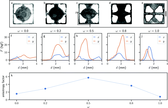
Now that we have shown that mechanical metamaterials with different fracture properties can lead to different mouthfeel experiences and even improve the overall tasting experience, we push their rational design one step further by using topology optimization to create maximally anisotropic structures. We devise an optimization problem that minimizes a quantity J1 when compressing the mechanical metamaterial in the vertical y direction and simultaneously maximizes another quantity J2 when compressing it in the horizontal x direction. J1 and J2 aggregate the energy release rates of every potential crack along the structural boundary. These are then combined into a single objective function J = ωJ1 − (1 − ω)J2, in which 0 ≤ ω ≤ 1 is a weight parameter. The multiobjective optimization problem has therefore been cast as a single objective problem using a simple weighted sum—see Methods for details about the computational approach.We run our topology optimization algorithm for multiple values of ω with a fixed volume fraction of 50%. As this volume constraint could become inactive when ω approaches zero, setting a bound on the volume may not be enough to guarantee a design with the target 50% volume fraction. Instead, we use two bounds and constrain the volume fraction to lie between 49.9% and 50.1%. For a value ω = 0, only the second term in J is non-zero, resulting in an optimized topology that is very brittle when compressed along x. Conversely, for ω = 1 only the first term in J is non-zero, with an optimized topology that makes the mechanical metamaterial very tough along y. Although the algorithm optimizes for fracture resistance, since chocolate is brittle, we expect the enhanced fracture anisotropy to also manifest itself via an enhanced strength anisotropy.23 Five optimized designs were 3D-printed in chocolate (Fig. 3a) and their mechanical properties were tested (Fig. 3b–f)—See Methods for printing and test protocols. The mechanical tests reveal that all structures have a similar force-displacement curve. Initial stiffness and maximum strength values are reported in Table II of the Methods; the maximum strength was obtained at compressive displacements between 1 and 2 mm. As expected, we find that the mechanical metamaterial displays a maximally anisotropic strength for ω = 0.5 (Fig. 3). This result can be interpreted from the geometry of the mechanical metamaterial, which has thin necks in the x direction and thick walls in the y direction. Such strong anisotropy is twice as large as that of the structure in Fig. 1, therefore we expect it to have to a strong ease of bite anisotropy.
Conclusions
To conclude, by designing, performing mechanical tests and carrying out sensory assessments of a range of edible mechanical metamaterials, we have shown that it is possible to control some features of the mouthfeel sensory experience, such as the perceived ease of bite and perceived number of cracks upon biting. We have further established that topology optimization is a powerful route to obtain metamaterials with on-demand anisotropy. Our work opens the door to new approaches for rational design of human-matter interactions and of fracture properties by using optimization methods for fracture, for edible products, but also engineering structures and beyond.Methods
Design approach
Due to the limitations imposed by the printing process—see 3D printing for a description of these—we decided to focus on geometries in which each layer could be printed in one continuous strand. These factors constrained us to the shapes shown on Fig. 1b and 2a–c. The various spirals were drawn in FreeCAD, an open-source and freely available CAD software package, whereas the S-structure is simply one of the predefined patterns available in Visual Machines, the control software for EnvisionTEC's 3D-Bioplotter. Whereas the latter contains several parallel beams, giving rise to its anisotropic properties, the spirals' interesting mouthfeel is less dependent on the biting direction. Overall, both designs rely on the same principle: the addition of breakable elements such as beams perpendicular to the direction of compression should result in a richer feeling in the mouth.Not only do the spirals possess a large number of breakable elements, the variable winding number (n) provides an obvious tuning parameter to find the sweet spot in terms of sensory perception. Initially, we tested winding numbers up to n = 7 for larger pieces but when printing bite-sized samples for the sensory study, we realized that n > 3 wasn't printable given the limited resolution—see 3D printing for an explanation. In the end, we arrived at 15 × 15 × 10 mm3 for the dimensions of the spirals and the S-structure. The reference shape is 15 × 15 × 4 mm3, making it thinner than the other shapes. This was done in an attempt to match the overall amount of chocolate deposited between different geometries.
3D printing
3D printing chocolate proved to be a challenging endeavor, due to the material's polymorphism.24 There are 6 different crystal forms of chocolate, each with their own mechanical properties and melting points. Typical chocolate products favor form V crystals, which tend to be shiny and smooth, producing audible snaps when bitten into.25 This particular crystal form melts at 34 °C26 so the working temperature of the chocolate must be kept under this value. We used Cacao Barry's Venezuela 72% dark chocolate, due to its advertised fluidity and high concentration of cacao—lower purity levels would further complicate the tempering and printing processes.Tempering was achieved using the seeding method, which consists of the following steps:
• Bring the chocolate temperature above the highest melting point of its different crystal forms (36 °C for form VI crystals). To ensure fully melted chocolate, we heated the material up to 45 °C.
• When the desired temperature is reached, turn the heating device off.
• Proceed to gradually add solid pellets of pre-tempered chocolate, stirring carefully, while monitoring the temperature of the liquid.
• When the temperature drops below the aforementioned melting point for form V crystals (34 °C), the chocolate is now ready to be printed.
The seeding process ensures that the right crystals are dispersed into the mix, acting as nucleation sites for further growth of the desired crystal form.
After tempering, the chocolate is loaded onto a syringe which is then inserted in the 3D-Bioplotter's heated cartridges, which are kept at 32 °C. To make sure that, after deposition, solidification happens as quickly as possible, the printing base is kept at 12 °C and a simple fan is used to create air flow.
In extrusion-based 3D printing, smaller nozzles are preferred due to the higher resolution they allow for, but we quickly realized that if the nozzle was too small, it would easily get blocked by the growing nucleation sites dispersed in the chocolate. So, we had a relatively large (1.2 mm) nozzle custom made, which worked effectively most of the time—we circumvented the limited resolution by working with single walled designs.
The 3D-Bioplotter uses air pressure to extrude the printing material. This means that a balance between air pressure and nozzle speed must be struck. We found that there was no consistent way to strike this balance, as the fluidity of chocolate seems to fluctuate when it is left unstirred inside the syringe. A printing session would often start with relatively low pressures (0.1 bar) and high speeds (40 mm s−1) but, as the chocolate thickened, we were forced to increase the pressure and to reduce the speed. Needless to say, the printing process requires frequent calibration to ensure that the printed lines have approximately constant thickness—matching the diameter of the nozzle.
Another common issue, related to the inconsistent fluidity of chocolate described here, was the over- or under-deposition of material at the beginning and end of each printed line. This too was calibrated and accounted for as much as possible, but unpredictable factors, such as the size of the droplet left on the nozzle after printing, made it challenging to fully eliminate this factor. Hence, we decided to focus on continuous strand designs, such that each layer could be printed in one go, leaving only two possible sites for the formation of irregularities (the beginning and the end of each line) (Tables 1–3).
| Syringe temperature (°C) | 32 |
| Platform temperature (°C) | 12 |
| Nozzle diameter (mm) | 1.2 |
| Nozzle speed (mm s−1) | 15–40 |
| Extrusion pressure (bar) | 0.1–2 |
| Sample | Strength (kgf) | Stiffness (kgf mm−1) | Volume fraction |
|---|---|---|---|
| S-Structure (x) | 3.41 | 4.11 | 0.64 |
| S-Structure (y) | 0.148 | 0.112 | 0.64 |
| Reference | 2.66 | 6.19 | 1.0 |
| Spiral (n = 1) | 0.0832 | 0.0761 | 0.32 |
| Spiral (n = 2) | 0.108 | 0.0613 | 0.48 |
| Spiral (n = 3) | 0.484 | 0.364 | 0.64 |
| TO, ω = 0.0 (x) | 4.23 | 3.99 | 0.50 |
| TO, ω = 0.0 (y) | 6.47 | 3.04 | 0.50 |
| TO, ω = 0.2 (x) | 7.00 | 3.89 | 0.50 |
| TO, ω = 0.2 (y) | 20.3 | 11.6 | 0.50 |
| TO, ω = 0.5 (x) | 4.76 | 7.41 | 0.50 |
| TO, ω = 0.5 (y) | 27.7 | 17.6 | 0.50 |
| TO, ω = 0.8 (x) | 8.84 | 6.08 | 0.50 |
| TO, ω = 0.8 (y) | 32.6 | 16.3 | 0.50 |
| TO, ω = 1.0 (x) | 17.7 | 21.4 | 0.50 |
| TO, ω = 1.0 (y) | 14.2 | 15.4 | 0.50 |
| Sample | Reference | Sp. (n = 1) | Sp. (n = 2) | Sp. (n = 3) | S-str. (x) | S-str. (y) | S-str. (z) | |||||||
|---|---|---|---|---|---|---|---|---|---|---|---|---|---|---|
| Av. | Dev. | Av. | Dev. | Av. | Dev. | Av. | Dev. | Av. | Dev. | Av. | Dev. | Av. | Dev. | |
| Crunchiness | 2.3 | 0.6 | 3.1 | 1.2 | 4.0 | 0.9 | 4.2 | 0.9 | 3.7 | 0.9 | 4.0 | 1.0 | 3.3 | 1.0 |
| Ease of bite | 2.9 | 1.0 | 4.3 | 0.9 | 4.1 | 0.5 | 3.5 | 0.8 | 3.3 | 0.8 | 3.9 | 0.8 | 3.1 | 1.1 |
| Normalized cracks | 1.1 | 0.6 | 2.2 | 0.6 | 3.6 | 0.8 | 4.1 | 0.9 | 3.2 | 1.1 | 4.3 | 1.0 | 2.4 | 0.9 |
| Overall rating | 2.8 | 0.4 | 2.9 | 0.8 | 4.2 | 0.6 | 4.1 | 0.5 | 3.5 | 0.5 | 4.0 | 0.4 | 3.0 | 1.0 |
Mechanical testing
Testing was done using an Instron 5943 uniaxial compression device. The samples were placed on a flat bed and crushed by a cylindrical rod attached to the movable arm of the machine; a constant compression speed of 5 mm s−1 was set. A 500 N load cell was used to register the force applied by the aforementioned cylindrical rod.During the compression, a Basler acA2040-90 μm camera was used to record pictures of the process, while a MiniDSP UMIK-1 microphone was used to capture audio.
The different samples were kept refrigerated right until the moment of testing, to ensure temperature uniformity across all tests.
Sensory assessment
The sensory study was performed by a panel of 10 untrained volunteers, recruited via email. The group was composed of students, researchers and technical staff, all unaware of the purpose of the study. Upon arrival in the testing room, they were provided with a printed questionnaire, containing instructions on how to handle and bite the pieces using their molars. The participants were also instructed to close their jaws at a deliberately slow pace, in an effort to match the conditions of the sensory study to those of the mechanical tests. Furthermore, the different samples were kept refrigerated until the moment of testing, spending only a few seconds exposed to the room temperature before being ingested. The order in which the samples were presented was randomized and each was assigned a codename, so as not to introduce any biases in its perceived properties. Between trials, the participants were allowed to take breaks to cleanse their palates with tap water. The participants were allowed to try each piece more than once, if necessary, to get a better sense of its characteristics. The participants were asked to focus specifically on the first bite, filling in their answers for each question based on their impressions of this experience.12,27 They were asked to rate each sample with a number between 1 and 5 for each of the following questions:• How crunchy was it?
• How easy was it to bite?
• How would you rate the overall experience?
Finally, the participants were asked to estimate the absolute number of cracks felt. The results for this particular question were then normalized as follows:
 | (1) |
Here, āi and ai are, respectively, the normalized and absolute values of the estimated number of cracks for a given sample i. This normalization was chosen to take into account different individual criteria for what counts as a crack. Note that the perceived ease of bite is related to the perceived thickness in the case of liquid products,12 which is the force needed to make the sample flow or deform in the mouth.
Topology optimization
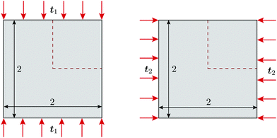
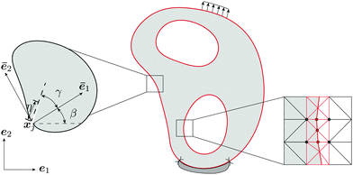
Topology optimization (TO)28,29 is a technique widely used in structural optimization that combines finite element analysis (FEA) with a gradient-based optimizer. Starting with a computational domain, the procedure seeks the most appropriate material layout to minimize a given objective function subject to given constraints. In this work we use TO to tailor fracture resistance30 and thus introduce anisotropy into the mechanical metamaterial structure to that end, we use two loading cases as shown in Fig. 4. Due to symmetry, we consider only a quarter of the domain during the optimization. Our objective function thus minimizes some measure of the energy release rate J1 when compressing the mechanical metamaterial in the vertical direction, while maximizes another value J2 when compressing along the horizontal direction. The optimization, which is also subject to a volume constraint of chocolate, is mathematically defined as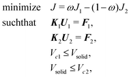 | (2) |
 | (3) |
 | (4) |
Our approach to topology optimization30,34 uses a level set function φ, whose zeroth value represents the interface between chocolate and void, an enriched finite element formulation to accurately determine the structural response, and the method of moving asymptotes (MMA) as the optimizer to update design variables. Noteworthy, energy release rates are computed at the locations of enriched nodes that are added to the finite element formulation to properly describe the discontinuous kinematics at void–solid interfaces. In comparison with standard density-based TO methods, our approach can provide smooth and crisp designs without the need for post-processing.30,34
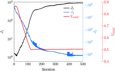
Fig. 6 shows the initial design containing four circular holes within the entire mechanical metamaterial cell (only one hole in our quarter optimization domain), where the ratio J2/J1 = 1. Starting from this initial design, the final optimized designs for different values of ω are shown in the same figure. As ω increases, more emphasis is placed on minimizing J1, which leads to more solid material being placed along the vertical direction. Conversely, as ω decreases, the designs that minimize −J2 (or maximize J2) have weak bars in the horizontal direction—thus maximizing energy release rates. Maximum anisotropy is attained for ω = 0.5, i.e., J2/J1 = 14.85. Fig. 7 shows the convergence of J1, J2, and Vsolid, where it can be seen that J1 increases and J2 decreases throughout the optimization process, and that the material volume fraction Vsolid converges to 50%. Since the magnitude of J2 is larger than that of J1, the optimizer gives priority to the former. Since optimized designs depend on the initial topology—because we use gradient information starting from the initial design—to study the variability in final designs we also looked at other initial layouts for ω = 0.5. The results of this study are given in Fig. 8, where we see that optimized structures are different than that shown in Fig. 6(f)—although the main features are retained. It should also be mentioned that optimized designs are also sensitive to the move limit used in MMA.
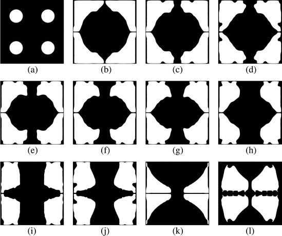 | ||
| Fig. 6 (a) Initial design with four holes in the whole design domain; (b)–(l) Final designs with different weights ω = 0, 0.1,…, 1. | ||
 | ||
| Fig. 8 (a and c) Initial designs with 16 holes and 24 holes, and (b and d) the corresponding final results obtained with ω = 0.5. | ||
Formulation of the topology optimization
Following the work of Silva et al.31 on topological derivatives, the matrix Q in eqn (4) is given by | (5) |
 | (6) |
![[thin space (1/6-em)]](https://www.rsc.org/images/entities/char_2009.gif) β and s = sin
β and s = sin![[thin space (1/6-em)]](https://www.rsc.org/images/entities/char_2009.gif) β. P(γ) is used to obtain stresses in polar coordinates, and it is given by
β. P(γ) is used to obtain stresses in polar coordinates, and it is given by | (7) |
![[thin space (1/6-em)]](https://www.rsc.org/images/entities/char_2009.gif) γ and s = sin
γ and s = sin![[thin space (1/6-em)]](https://www.rsc.org/images/entities/char_2009.gif) γ. As stated in the work of Beghini et al.,35H(γ) is a 2 × 2 matrix associated with angle γ, with components
γ. As stated in the work of Beghini et al.,35H(γ) is a 2 × 2 matrix associated with angle γ, with components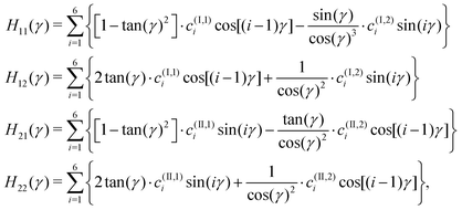 | (8) |
| i | c (I,1) i | c (II,1) i | c (I,2) i | c (II,2) i |
|---|---|---|---|---|
| 1 | −0.174856 | −0.198196 | −0.419098 | 0.478653 |
| 2 | 1.393783 | 0.681479 | −0.197271 | −0.130868 |
| 3 | −0.278259 | −0.282608 | −0.445897 | 0.663435 |
| 4 | 0.240695 | 0.136522 | −0.050066 | −0.066599 |
| 5 | −0.071883 | −0.041562 | −0.022856 | 0.183693 |
| 6 | 0.011246 | 0.006177 | 0.003281 | −0.006140 |
Sensitivity
The sensitivity of the objective function J with respect to a design variable σ is derived by using the adjoint variable method. The Lagrangian function of the objective constructed by using the adjoint vectors λ1 and λ2 is expressed as | (9) |
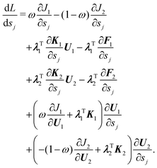 | (10) |
 | (11) |
 | (12) |
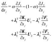 | (13) |
According to eqn (3) and (4), the derivative ∂Ji/∂Ui, i = 1, 2 can be expressed as
 | (14) |
 | (15) |
 | (16) |
 | (17) |
Conflicts of interest
There are no conflicts to declare.Acknowledgements
We thank A. Deblais for insightful discussions and suggestions, S. Koot and D. Giesen for technical assistance. We acknowledge funding from an IXA Physics2market grant. C. C. acknowledges funding from the European Research Council via the Grant ERC-StG-Coulais-852587-Extr3Me. All the codes and data supporting this study are available on the public repository https://doi.org/10.5281/zenodo.4632399.References
- M. Kadic, T. Bückmann, R. Schittny and M. Wegener, Metamaterials beyond electromagnetism, Rep. Prog. Phys., 2013, 76(12), 126501 CrossRef PubMed.
- K. Bertoldi, V. Vitelli, J. Christensen and M. van Hecke, Flexible mechanical metamaterials, Nat. Rev. Materials, 2017, 2(11), 17066 CrossRef CAS.
- D. M. Kochmann and K. Bertoldi, Exploiting Microstructural Instabilities in Solids and Structures: From Metamaterials to Structural Transitions, Appl. Mech. Rev., 2017, 69(5), 050801 CrossRef.
- X. Zheng, W. Smith, J. Jackson, B. Moran, H. Cui and D. Chen, et al., Multiscale metallic metamaterials, Nat. Mater., 2016, 15(10), 1100–1106 CrossRef CAS PubMed.
- S. Shan, S. H. Kang, J. R. Raney, P. Wang, L. Fang and F. Candido, et al., Multistable Architected Materials for Trapping Elastic Strain Energy, Adv. Mater., 2015, 27(29), 4296–4301 CrossRef CAS PubMed.
- T. Chen, M. Pauly and P. M. Reis, A reprogrammable mechanical metamaterial with stable memory, Nature, 2021, 589(7842), 386–390 CrossRef CAS PubMed.
- C. Coulais, E. Teomy, K. de Reus, Y. Shokef and M. van Hecke, Combinatorial design of textured mechanical metamaterials, Nature, 2016, 535(7613), 529–532 CrossRef CAS PubMed.
- M. M. Driscoll, B. G. Chen, T. H. Beuman, S. Ulrich, S. R. Nagel and V. Vitelli, The role of rigidity in controlling material failure, Proc. Natl. Acad. Sci. U. S. A., 2016, 113(39), 10813–10817 CrossRef CAS PubMed.
- N. P. Mitchell, V. Koning, V. Vitelli and W. T. Irvine, Fracture in sheets draped on curved surfaces, Nat. Mater., 2017, 16(1), 89–93 CrossRef CAS PubMed.
- C. Bonatti and D. Mohr, Mechanical performance of additively-manufactured anisotropic and isotropic smooth shell-lattice materials: simulations & experiments, J. Mech. Phys. Solids, 2019, 122, 1–26 CrossRef CAS.
- M. H. Tunick, C. I. Onwulata, A. E. Thomas, J. G. Phillips, S. Mukhopadhyay and S. Sheen, et al., Critical Evaluation of Crispy and Crunchy Textures: A Review, Int. J. Food Properties, 2013, 16(5), 949–963 CrossRef.
- A. Deblais, E. D. Hollander, C. Boucon, A. E. Blok, B. Veltkamp and P. Voudouris, et al., Predicting thickness perception of liquid food products from their non-Newtonian rheology, Nat. Commun., 2021, 12(1), 6328 CrossRef CAS.
- M. Aguayo-Mendoza, M. Santagiuliana, X. Ong, B. Piqueras-Fiszman, E. Scholten and M. Stieger, How addition of peach gel particles to yogurt affects oral behavior, sensory perception and liking of consumers differing in age, Food Res. Int., 2020, 134, 109213 CrossRef PubMed.
- A. van Eck, A. van Stratum, D. Achlada, B. Goldschmidt, E. Scholten and V. Fogliano, et al., Cracker shape modifies ad libitum snack intake of crackers with cheese dip, Br. J. Nutr., 2020, 124(9), 988–997 CrossRef CAS PubMed.
- A. Piovesan, V. Vancauwenberghe, W. Aregawi, M. A. Delele, E. Bongaers and M. de Schipper, et al., Designing Mechanical Properties of 3D Printed Cookies through Computer Aided Engineering, Foods, 2020, 9(12), 1804 CrossRef CAS PubMed.
- H. S. Tan, Y. T. Verbaan and M. Stieger, How will better products improve the sensory-liking and willingness to buy insect-based foods?, Food Res. Int., 2017, 92, 95–105 CrossRef PubMed.
- P. L. Fuhrmann, G. Sala, M. Stieger and E. Scholten, Effect of oil droplet inhomogeneity at different length scales on mechanical and sensory properties of emulsion-filled gels: length scale matters, Food Hydrocolloids, 2020, 101 Search PubMed.
- M. Santagiuliana, M. Christaki, B. Piqueras-Fiszman, E. Scholten and M. Stieger, Effect of mechanical contrast on sensory perception of heterogeneous liquid and semi-solid foods, Food Hydrocolloids, 2018, 83, 202–212 CrossRef CAS.
- J. I. Lipton, M. Cutler, F. Nigl, D. Cohen and H. Lipson, Additive manufacturing for the food industry, Trends Food Sci. Technol., 2015, 43(1), 114–123 CrossRef CAS.
- P. J. Lillford, The Importance of Food Microstructure in Fracture Physics and Texture Perception, J. Texture Studies, 2011, 42(2), 130–136 CrossRef.
- L. Wasserman, All of Statistics: A Concise Course in Statistical Inference. Springer, 2010 Search PubMed.
- M. Zampini and C. Spence, Assessing the Role of Sound in the Perception of Food and Drink, Chemosens. Percept., 2010, 3(1), 57–67 CrossRef.
- R. G. Munro and S. W. Freiman, Correlation of Fracture Toughness and Strength, J. Am. Ceram. Soc., 2004, 82(8), 2246–2248 CrossRef.
- L. Hao, S. Mellor, O. Seaman, J. Henderson, N. Sewell and M. Sloan, Material characterisation and process development for chocolate additive layer manufacturing, Virtual Phys. Prototyping, 2010, 5(2), 57–64 CrossRef.
- S. Beckett, The Science of Chocolate. The Royal Society of Chemistry, 2008 Search PubMed.
- H. Schenk and R. Peschar, Understanding the structure of chocolate, Radiation Phys. Chem., 2004, 71(3), 829–835 CrossRef CAS . 9th International Symposium on Radiation Physics (ISRP-9).
- S. Zhu, M. Ribberink, M. de Wit, M. Schutyser and M. Stieger, Modifying sensory perception of chocolate coated rice waffles through bite-to-bite contrast: an application case study using 3D inkjet printing, Food Funct., 2020, 11, 10580–10587 RSC.
- M. P. Bendsøe and N. Kikuchi, Generating optimal topologies in structural design using a homogenization method, Comput. Methods Appl. Mech. Eng., 1988, 71(2), 197–224 CrossRef.
- O. Sigmund, Design of material structures using topology optimization. Department of Solid Mechanics, Technical University of Denmark, 1994 Search PubMed.
- J. Zhang, F. van Keulen and A. M. Aragón, On tailoring fracture resistance of brittle structures: A level set interface-enriched topology optimization, Computer Methods in Applied Mechanics and Engineering, 2022, 388, 114189 CrossRef.
- M. Silva, P. H. Geubelle and D. A. Tortorelli, Energy release rate approximation for small surface-breaking cracks using the topological derivative, J. Mech. Phys. Solids, 2011, 59(5), 925–939 CrossRef.
- Z. Kang, L. Pai and M. Li, Topology optimization considering fracture mechanics behaviors at specified locations, Structural and Multidisciplinary Optimization, 2017, 55(5), 1847–1864 CrossRef.
- J. Hu, S. Yao, N. Gan, Y. Xiong and X. Chen, Fracture strength topology optimization of structural specific position using a bi-directional evolutionary structural optimization method, Eng. Optimization, 2019, 583, DOI:10.1080/0305215X.2019.1609466.
- S. J. van den Boom, J. Zhang, F. van Keulen and A. M. Aragón, An interface-enriched generalized finite element method for level set-based topology optimization, Structural and Multidisciplinary Optimization, 2021, 63(1), 1–20 CrossRef.
- M. Beghini, L. Bertini and V. Fontanari, Stress intensity factors for an inclined edge crack in a semiplane, Eng. Fract. Mech., 1999, 62(6), 607–613 CrossRef.
| This journal is © The Royal Society of Chemistry 2022 |

