The role of an inert shell in improving energy utilization in lanthanide-doped upconversion nanoparticles†
Yu
Wang
 ab
ab
aSZU-NUS Collaborative Center and International Collaborative Laboratory of 2D Materials for Optoelectronic Science & Technology of Ministry of Education, College of Optoelectronic Engineering, Shenzhen University, Shenzhen 518060, China. E-mail: wangyu@szu.edu.cn
bEngineering Technology Research Center for 2D Material Information Function Devices and Systems of Guangdong Province, College of Optoelectronic Engineering, Shenzhen University, Shenzhen 518060, China
First published on 14th May 2019
Abstract
Coating with an inert shell is considered an efficient approach for enhancing the emission and improving the luminescence quantum yield of lanthanide-doped upconversion nanoparticles. In this work, the role of an inert shell in the photon energy collection and energy transfer behavior is carefully studied. Our experimental results indicate that, owing to the valid energy trapping by the shell, an energy clustering effect is formed among the Yb3+ ions in the core. Such an effect reduces the total absorption and enhances the upconversion emission, especially the emission from the higher lying level of lanthanide emitters. Moreover, the morphology of the inert shell, which could be controlled during our synthesis, is deemed to be critical to the formation of energy clustering.
Introduction
Driven and motivated by various applications, the research and development of lanthanide-doped upconversion nanoparticles (UCNPs) has attracted much attention in the past decade.1–13 Some lanthanide rare earth ion emitters (Er3+, Tm3+, Ho3+, etc.) gain the ability to convert near-infrared (NIR) excitation into shorter wavelengths when they are located in an inorganic crystal matrix. Fluorides or oxides are commonly chosen as the host matrix because of their low phonon energy, which is beneficial for the population of the high energy level in lanthanide emitters. Normally, host materials with only emitter doping do not exhibit ideal upconversion luminescent performance owing to their less efficient ground state absorption (GSA) and excited state absorption (ESA) processes. In well-designed upconversion materials, Yb3+ or Nd3+ sensitizers are necessarily used as sensitizers to absorb the excitation irradiation energy, then lanthanide emitters doped in materials can capture the energy from adjacent Yb3+ sequentially and easily. The efficiency of the energy transfer upconversion (ETU) process is considered two orders of magnitude higher than that of ESA upconversion.1However, it is worth mentioning that the low efficiency of the upconversion process is definitely an obstacle for the application of UCNPs. Actually, the simultaneously down-conversion process also accounts for the low efficiency of such UCNPs. So far, many different attempts have been made at enhancing upconversion luminescence in lanthanide-doped nanocrystals.14 Among all these strategies, coating with an inert shell is considered one of the most facile and efficient approaches to enhance both the emission intensity and absolute quantum yield of upconversion nanoparticles.14–25 So far, the enhancement of the luminescence effect by the inert shell is mostly attributed to the following acknowledged reasons: (1) the inert shell, as a spacer, isolates the excitation energy in the core from the quenching effect by the ligands or solvent molecules; and (2) the incomplete crystal lattice located at the core surface can be modified by the inert shell. As a result, emitters on the core surface are aroused. Recently, it has been found that the concentration quenching in upconversion nanoparticles can be effectively eliminated by employing an inert shell.26–28 However, the utilization of the excitation photon energy in the core and the energy transfer process among doping ions are still ambiguous. In this work, based on the investigation of the absorption capability and the direction of the energy transfer process in upconversion nanoparticles, we consider that the inert shell promotes the energy clustering effect among Yb3+ ion in the core, which elevates the coefficient of energy utilization (Fig. 1), especially in the situation of Yb3+ highly doped UCNPs. Furthermore, the morphology of the inert shell could be controlled during the epitaxial growth process and the energy clustering effects induced by different shaped shells are studied.
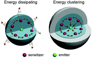 | ||
| Fig. 1 Schematic illustration of the energy transfer behaviors in upconversion nanoparticles with and without an inert shell coating. | ||
Results and discussion
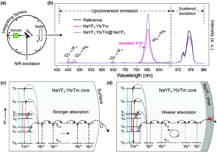
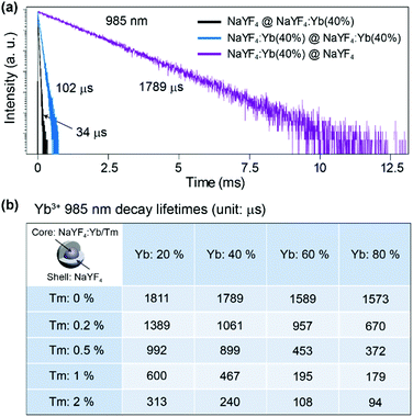
Firstly we utilized Yb/Tm co-doped UCNPs to study the effect of the inert shell. The NaYF4:Yb/Tm(40/2%) core UCNPs were prepared via co-precipitation method.29 TEM images show that the NaYF4:Yb/Tm(40/2%) core and the NaYF4:Yb/Tm(40/2%)@NaYF4 core–shell structured UCNPs have very uniform size distributions with average diameters of 19.1 and 23.9 nm, respectively (Fig. S1†). The upconversion luminescent spectra of the UCNPs can be obtained from a spectrum instrument setup with an integrating sphere (Fig. 2a). A quartz cuvette containing UCNPs dispersed in cyclohexane is laid in a holder in the 15 cm diameter integrating sphere in our experiment (Fig. S3†). An external 975 nm laser is imported to excite the UCNP samples. The excitation laser beam scattered by the samples in the integrating sphere is recorded in a spectrometer equipped with a photomultiplier tube (PMT), which covers the wavelength range from UV to NIR. The amount of absorption by a sample is calculated by the difference between the scattered excitation intensities for the sample and a blank reference (pure cyclohexane). The total upconversion emission intensity of NaYF4:Yb/Tm(40/2%) UCNPs is largely increased after shell coating. Unexpectedly, we noticed that compared with the NaYF4:Yb/Tm(40/2%) core nanoparticle, the absorption of the NaYF4:Yb/Tm(40/2%)@NaYF4 core–shell particle at 975 nm is lessened to 24% (Fig. 2b), which means that the inert shell decreases the NIR excitation absorption by the core, but inversely enhances the upconversion emission. The calculated quantum yields of the core and core–shell nanoparticles are 0.30% and 5.60%, respectively. We assume that in the case of the bare core, Yb3+ ions absorb a larger amount of excitation photon energy, most of which is dissipated, so only a tiny amount of energy could be transferred to Tm3+ to form a very weak upconversion emission (Fig. 2c). In contrast, with the protection of the inert shell, the absorbed photon energy, which is possibly constrained by the shell, tends to transfer to Tm3+ and generate a very intense emission.To understand the mechanism, core–shell structured NaYF4 nanoparticles with single Yb3+ doping in different areas were designed and prepared (Fig. S4†). Each sample is dispersed in cyclohexane with a concentration of 0.05 mmol mL−1 and loaded in a 4 mL standard quartz cuvette, which is placed in an integrating sphere. We found that the intensity of the 975 nm NIR laser beam is decreased by 2%, 11%, 31%, and 35% after passing through the NaYF4@NaYF4, NaYF4:Yb(40%)@NaYF4, NaYF4@NaYF4:Yb(40%), and NaYF4:Yb(40%)@NaYF4:Yb(40%) nanoparticles, respectively (Fig. S5†). Obviously, pure NaYF4 nanocrystals barely absorb NIR excitation photons. Nanoparticles with Yb3+ ions in the shell absorb more NIR photons than the same amount of Yb3+ ions in the core. We conclude that a large amount of the absorbed NIR photon energy is transferred to the surface quenching centers and dissipated extremely quickly, which results in a very short decay (34 μs) of the 985 nm Yb3+ luminescence (Fig. 3a). Excited Yb3+ ions quickly drop down to the 2F7/2 ground state, which means a large amount of Yb3+ ions become available to absorb new coming photons. Oppositely, if Yb3+ ions are doped only in the inner core, owing to the isolation by the NaYF4 shell spacer, the absorbed NIR photon energies are mostly hopped among Yb3+ ions and constrained in the core, instead of being quenched by the crystal surface. The excited states of Yb3+ ions are kept occupied, which led to an extremely slow decay time of 985 nm Yb3+ emission (1789 μs). The long lifetime of the excited state in Yb3+ ions hindered the continuous absorption of NIR-excited photons.
Furthermore, when emitters, such as Tm3+ ions, are co-doped in nanoparticles with Yb3+ ions, the absorbed NIR energy is easily transferred among Yb3+ ions owing to the relatively high concentration of Yb3+ in the particles, until being captured by Tm3+ ions. In the case of bare core nanoparticles, a large proportion of the Yb3+ ions are exposed on the particle surface, since most of the absorbed NIR photon energy is dissipated by surface quenchers, instead of being transferred to emitters (Fig. 2c). We have reason to believe that the energy transfer rate from the Yb3+ to the surface quenchers is much faster than that from the Yb3+ to the emitters. That is the key reason for the weak emission and the low quantum yield of bare core UCNPs. On the contrary, under the protection of an inert shell, the excitation photon energy absorbed by the Yb3+ can be efficiently transferred to the emitters (Fig. 2d). In NaYF4:Yb/Tm@NaYF4 nanoparticles with fixed 40% Yb3+ in the core, the 985 nm Yb3+ decay lifetime decreased to 1061, 899, 467 and 240 μs when the Tm3+ doping concentration was increased to 0.2%, 0.5%, 1% and 2%, respectively (Fig. 3b and Fig. S6†). Therefore, stronger upconversion emission intensity and higher quantum yield are obtained from core–shell UCNPs.
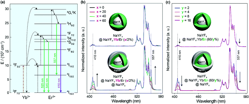
To verify the energy clustering effect30 among Yb3+ induced by the inert shell, core–shell structured NaYF4@NaYF4:Yb/Er(x/2%) UCNPs with dopants in the outer layer were prepared and the upconversion spectra of Er3+ were studied. Herein, the inner core of a pure NaYF4 crystal is used as the seed to control the starting size and make sure the doping area is sensitive to the surface environment. From Fig. 4b it can be seen that the NaYF4@NaYF4:Yb/Er(x/2%) UCNPs just emit very weak 410 nm violet emissions (attributed to the transition of 2H9/2 → 4I15/2 in Er3+) compared to green emissions (2H11/2, 4S3/2 → 4I15/2 transitions). The peak at 557 nm is attributed to the 2H9/2 → 4I13/2 transition, which shows the same variation trend as the 2H9/2 → 4I15/2 410 nm violet emission. The intensity ratio of the violet-to-green emission of particles with different Yb3+ concentrations is rarely varied and stayed at a very low level. However, with NaYF4 shell protection, a gradual increase in the violet-to-green emission ratio with the increase of the Yb3+ concentration is observed. A large proportion of the 2H9/2 energy level in Er3+ can be populated by energy transfer from Yb3+ to Er3+. This should be attributed to the fact that the inert shell promotes the formation of the energy clustering effect inside the doping layer, thus the energy can be effectively trapped by the energy cluster in the UCNPs with a higher Yb3+ doping concentration. To study the effect of Er3+ ions, the Yb3+ concentration was firstly fixed at 60% in the doping layer. With the increase of the Er3+ doping concentration from 2% to 16%, the intensity ratio of the violet-to-green emission gradually decreased (Fig. 4c). This could be attributed to the fact that the increased interaction between Er3+ ions quenches each other's luminescence to depopulate the 2H9/2 level, no matter if the nanoparticles have an inert shell or not.
The enhancement factor is considered important for evaluating the gain of a luminescent enhancing strategy. It is well known that a thicker shell results in a greater luminescent enhancement factor on the emitting core.18 Besides, according to our experimental results, core nanoparticles with more dopants inside show greater enhancement factors after coating with a similar thickness of inert shell (Fig. S7†).21 As it is known, dopants quench each other's luminescence, especially when the distances between dopants are very close. Experimental results validate that the greater the quenching effect in the core, the more luminescence capability that can be recovered by the inert shell, which means that a higher enhancement factor can be obtained. Moreover, it can be concluded that a thicker shell is beneficial for the formation of the Yb3+ energy clustering effect (Fig. S8†).
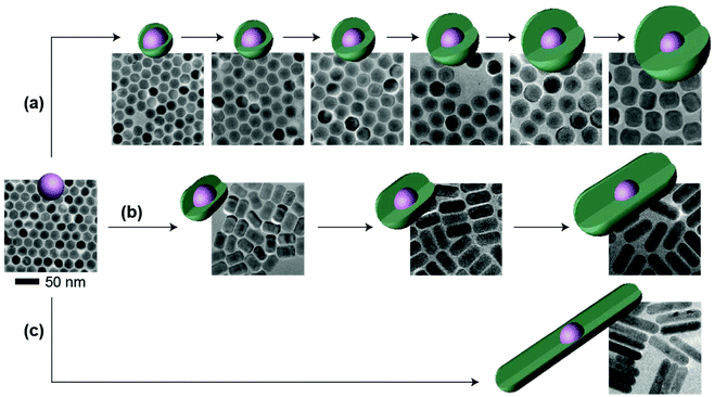
Other than the doping concentration and the thickness of the shell, the morphology of the inert shell is also considered as a factor that possibly influences the luminescence. The one-pot heating-up method is a commonly used way to prepare core–shell structured UCNPs. In this work, we found that the crystal growth speed of the shell in different directions is related to the molar ratio of the core to the shell precursor (Fig. 5 and Fig. S9†). Sphere-like shaped core–shell structure nanoparticles can be obtained by multi-step epitaxial shell growth with the molar ratio of the shell precursor and the core maintained at 1![[thin space (1/6-em)]](https://www.rsc.org/images/entities/char_2009.gif) :
:![[thin space (1/6-em)]](https://www.rsc.org/images/entities/char_2009.gif) 1 (Fig. 5a). The ratio of the length to the width of rod-like shape nanoparticles is determined by the precursor amount in each shell growth step. When the ratio of the shell precursor to the core is increased to 2
1 (Fig. 5a). The ratio of the length to the width of rod-like shape nanoparticles is determined by the precursor amount in each shell growth step. When the ratio of the shell precursor to the core is increased to 2![[thin space (1/6-em)]](https://www.rsc.org/images/entities/char_2009.gif) :
:![[thin space (1/6-em)]](https://www.rsc.org/images/entities/char_2009.gif) 1, the growth rate along the c-axis is faster than that in the lateral direction and larger length-to-width ratio nanorods are finally developed (Fig. 5b). On further increasing the ratio of the shell precursor to the core to 6
1, the growth rate along the c-axis is faster than that in the lateral direction and larger length-to-width ratio nanorods are finally developed (Fig. 5b). On further increasing the ratio of the shell precursor to the core to 6![[thin space (1/6-em)]](https://www.rsc.org/images/entities/char_2009.gif) :
:![[thin space (1/6-em)]](https://www.rsc.org/images/entities/char_2009.gif) 1, with enough reaction time (Fig. S10†), the epitaxial growth happens almost entirely along the c-axis (Fig. 5c). When we tested the emission spectra of the three final core–shell structured UCNPs obtained via the three different routes, it was observed that the sphere-like shell coating nanoparticles showed greater high-level upconversion emission (2H9/2 → 4I15/2) (Fig. 6), which can be attributed to the better shielding effect in the emitting core by the sphere-like inert shell, thus an energy cluster could be formed in a greater way in the core. In the rod-shaped core–shell structure UCNPs, although energy could not be lost lengthways, the lateral directions are too thin to isolate the surface quenchers (Fig. S11†). Thus, the upconversion emission from the high level of Er3+ is relatively weak. These results indicate that in order to seal the energy in the core as much as possible, the inert shell should be grown on the emitting core isotropically.
1, with enough reaction time (Fig. S10†), the epitaxial growth happens almost entirely along the c-axis (Fig. 5c). When we tested the emission spectra of the three final core–shell structured UCNPs obtained via the three different routes, it was observed that the sphere-like shell coating nanoparticles showed greater high-level upconversion emission (2H9/2 → 4I15/2) (Fig. 6), which can be attributed to the better shielding effect in the emitting core by the sphere-like inert shell, thus an energy cluster could be formed in a greater way in the core. In the rod-shaped core–shell structure UCNPs, although energy could not be lost lengthways, the lateral directions are too thin to isolate the surface quenchers (Fig. S11†). Thus, the upconversion emission from the high level of Er3+ is relatively weak. These results indicate that in order to seal the energy in the core as much as possible, the inert shell should be grown on the emitting core isotropically.
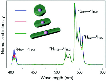 | ||
| Fig. 6 NIR (975 nm) excited upconversion luminescence spectra of NaYF4:Yb/Er@NaYF4 UCNPs with different shaped shells. All spectra are normalized to Er3+ emission at 540 nm. | ||
Conclusions
In conclusion, coating with an inert shell is an efficient strategy for obtaining high quantum yield upconversion nanomaterials. The long lifetime of the excited state level in Yb3+ caused by the inert shell suppresses the absorption to the excitation photon. Yb3+ ions in the core tend to form energy clusters upon the isolation of the inert shell to efficiently use excitation photon energy and transfer the energy to luminescence, especially the luminescence generated from the high-lying level of lanthanide emitters. To sum up, the quantum yield enhancement of upconversion nanoparticles by inert shell protection is attributed to both the improved luminescence and the decreased absorption.Experimental section
Materials
Yttrium(III) acetate hydrate (Y(CH3CO2)3; 99.9%), ytterbium(III) acetate hydrate (Yb(CH3CO2)3; 99.9%), thulium acetate hydrate (Tm(CH3CO2)3; 99.9%), erbium(III) acetate hydrate (Er(CH3CO2)3; 99.9%), sodium hydroxide (NaOH; >98%), ammonium fluoride (NH4F; >98%), 1-octadecene (90%), oleic acid (90%) and hydrochloric acid were all purchased from Sigma-Aldrich and used as received without further purification. Analytical-grade ethanol and cyclohexane were purchased from Sigma-Aldrich.Synthesis of NaREF4 (RE = Y/Yb/Tm/Er) nanoparticles
The upconversion nanoparticles were synthesized using a modified wet-chemical procedure.29 In a typical experiment, to a 50 mL flask containing 3 mL of oleic acid (OA) and 7 mL of 1-octadecene (ODE) was added 2 mL of water solution containing RE(CH3CO2)3 (RE = Y/Yb/Tm/Er) at various ratios with a total lanthanide amount of 0.4 mmol. The resulting mixture was heated at 150 °C to vaporize water, and then cooled down to 50 °C when it became transparent lanthanide oleate complexes. Subsequently, a methanol solution (6 mL) containing NH4F (1.6 mmol) and NaOH (1 mmol) was added and stirred for half an hour. The reaction temperature was then increased to 110 °C to remove the methanol from the reaction mixture. After 0.5 hours, the solution was heated to 290 °C and maintained at this temperature under argon flow protection for 2 h, at which time the mixture was cooled down to room temperature. The resulting nanoparticles were precipitated out through the addition of ethanol, collected by centrifugation (5000 rpm, 10 min), washed with ethanol twice, and finally dispersed in cyclohexane for further use.Synthesis of NaREF4@NaREF4 (RE = Y/Yb/Tm/Er) core–shell nanoparticles
The shell precursor was prepared by mixing RE(CH3CO2)3 (RE = Y/Yb/Er/Tm), 3 mL of OA and 7 mL of ODE in a 50 mL flask followed by heating at 150 °C for 1 h. After cooling down to 80 °C, 0.2 mmol of NaREF4 (RE = Y/Yb/Tm/Er) core nanoparticles dispersed in 2 mL of cyclohexane was added. The mixture was cooled down to 50 °C naturally after 30 min, then proper amounts of NH4F and NaOH in methanol were added. To remove the methanol from the reaction mixture, the reaction temperature was then increased to 110 °C and maintained for 0.5 h. Afterwards, the solution was heated to 290 °C and maintained at this temperature under argon flow. The reaction time (2–6 h) is dependent on the amount of reactant. The mixture was then cooled down to room temperature. The resulting nanoparticles were precipitated out through the addition of ethanol, collected by centrifugation, washed with ethanol, and dispersed in 4 mL of cyclohexane. The multi-shell nanoparticles were prepared by repeating the procedure mentioned above but only changing the components ratio of the lanthanides.Characterization
Powder X-ray diffraction (XRD) data were recorded on a Siemens D5005 X-ray diffractometer with Cu Kα radiation (λ = 1.5406 Å). Transmission electron microscopy (TEM) measurements were carried out on a JEOL-1400 transmission electron microscope (JEOL) operating at an acceleration voltage of 100 kV. The upconversion luminescence spectra under 975 nm excitation were recorded using an Edinburgh FSP920-C equipped with a photomultiplier (PMT) in conjunction with a 975 nm diode laser (1 W). The spectral response of the PMT was precisely corrected by Edinburgh Corp. The CW laser beam was applied onto samples contained in a quartz cuvette with a path length of 1 cm. The emission from the samples was collected at an angle of 90° to the excitation beam by a pair of lenses. The decay curves of the upconversion emission were measured using a customized phosphorescence lifetime spectrometer (FSP920-C, Edinburgh) and a tunable NT352A Nd:YAG laser system as an excitation source. The NT352A is a parametric generator pumped by a 532 nm second harmonic output of a Nd:YAG laser, and comprises an NL300 pump laser, a harmonics generator (SHG) and an optical parametric oscillator (OPO). The absorption and absolute upconversion quantum yield were measured using a steady-state spectrometer couple with an integrating sphere (150 mm diameter; internally coated with barium sulfate) and a 975 nm diode laser. The excitation light was first introduced to the integrating sphere from the entrance port, then reflected by a reflecting mirror and accepted by the sample. The emission and the reflected excitation were scattered by the inner wall of the integrating sphere and then detected by an extended red-sensitive photomultiplier (spectral range 200–1010 nm) near the exit port. A 1/50 neutral density filter was employed to attenuate the intensity of the scattered laser radiation to avoid saturating the detector. The upconversion quantum yield is determined by QY = L/(Eref − E), where L denotes the integrated emission intensity of the sample, and Eref and E are the integrated intensities of the excitation light that is not absorbed by the reference or the sample, respectively. For colloidal sample measurement, 0.2 mmol of the nanoparticles to be measured were dispersed in 3 mL of cyclohexane and then filled in a cuvette. A second identical cuvette filled with 3 mL of cyclohexane was utilized as the reference.Conflicts of interest
There are no conflicts to declare.Acknowledgements
This study was supported by the National Natural Science Foundation of China (grant 61705137), the Natural Science Foundation of SZU (grant 2017024), the Science and Technology Project of Shenzhen (grant JCYJ20170817093821657, KQJSCX20180328093614762, ZDSYS201707271014468), and the Educational Commission of Guangdong Province (grant 2016KCXTD006).Notes and references
- F. Auzel, Chem. Rev., 2004, 104, 139–173 CrossRef CAS PubMed.
- F. Wang, D. Banerjee, Y. Liu, X. Chen and X. Liu, Analyst, 2010, 135, 1839–1854 RSC.
- S. S. Lucky, K. C. Soo and Y. Zhang, Chem. Rev., 2015, 115, 1990–2042 CrossRef CAS PubMed.
- X. Liu, R. Deng, Y. Zhang, Y. Wang, H. Chang, L. Huang and X. Liu, Chem. Soc. Rev., 2015, 44, 1479–1508 RSC.
- X. Li, F. Zhang and D. Zhao, Chem. Soc. Rev., 2015, 44, 1346–1378 RSC.
- H. Dong, L. D. Sun and C. H. Yan, Chem. Soc. Rev., 2015, 44, 1608–1634 RSC.
- G. Chen, H. Agren, T. Y. Ohulchanskyy and P. N. Prasad, Chem. Soc. Rev., 2015, 44, 1680–1713 RSC.
- E. M. Chan, Chem. Soc. Rev., 2015, 44, 1653–1679 RSC.
- Y. Wang, K. Zheng, S. Song, D. Fan, H. Zhang and X. Liu, Chem. Soc. Rev., 2018, 47, 6473–6485 RSC.
- S. Chen, A. Z. Weitemier, X. Zeng, L. M. He, X. Y. Wang, Y. Q. Tao, A. J. Y. Huang, Y. Hashimotodani, M. Kano, H. Iwasaki, L. K. Parajuli, S. Okabe, D. B. L. Teh, A. H. All, I. Tsutsui-Kimura, K. F. Tanaka, X. G. Liu and T. J. McHugh, Science, 2018, 359, 679–683 CrossRef CAS PubMed.
- J. Zhou, S. Wen, J. Liao, C. Clarke, S. A. Tawfik, W. Ren, C. Mi, F. Wang and D. Jin, Nat. Photonics, 2018, 12, 154–158 CrossRef CAS.
- C. Zhang and J. Y. Lee, ACS Nano, 2013, 7, 4393–4402 CrossRef CAS PubMed.
- D. Wang, B. Liu, Z. Quan, C. Li, Z. Hou, B. Xing and J. Lin, J. Mater. Chem. B, 2017, 5, 2209–2230 RSC.
- S. Han, R. Deng, X. Xie and X. Liu, Angew. Chem., Int. Ed., 2014, 53, 11702–11715 CrossRef CAS PubMed.
- G.-S. Yi and G.-M. Chow, Chem. Mater., 2007, 19, 341–343 CrossRef CAS.
- H. X. Mai, Y. W. Zhang, L. D. Sun and C. H. Yan, J. Phys. Chem. C, 2007, 111, 13721–13729 CrossRef CAS.
- Y. Wang, L. Tu, J. Zhao, Y. Sun, X. Kong and H. Zhang, J. Phys. Chem. C, 2009, 113, 7164–7169 CrossRef CAS.
- Y. Wang, K. Liu, X. M. Liu, K. Dohnalova, T. Gregorkiewicz, X. G. Kong, M. C. G. Aalders, W. J. Buma and H. Zhang, J. Phys. Chem. Lett., 2011, 2, 2083–2088 CrossRef CAS.
- Q. Su, S. Han, X. Xie, H. Zhu, H. Chen, C. K. Chen, R. S. Liu, X. Chen, F. Wang and X. Liu, J. Am. Chem. Soc., 2012, 134, 20849–20857 CrossRef CAS PubMed.
- J. C. Boyer and F. C. van Veggel, Nanoscale, 2010, 2, 1417–1419 RSC.
- T. Sun, R. Ma, X. Qiao, X. Fan and F. Wang, ChemPhysChem, 2016, 17, 766–770 CrossRef CAS PubMed.
- L. Liang, X. Qin, K. Zheng and X. Liu, Acc. Chem. Res., 2018, 52, 228–236 CrossRef PubMed.
- C. Homann, L. Krukewitt, F. Frenzel, B. Grauel, C. Wurth, U. Resch-Genger and M. Haase, Angew. Chem., Int. Ed. Engl., 2018, 57, 8765–8769 CrossRef CAS PubMed.
- D. Hudry, I. A. Howard, R. Popescu, D. Gerthsen and B. S. Richards, Adv. Mater., 2019, 1900623 CrossRef PubMed.
- X. Xu, C. Clarke, C. Ma, G. Casillas, M. Das, M. Guan, D. Liu, L. Wang, A. Tadich, Y. Du, C. Ton-That and D. Jin, Nanoscale, 2017, 9, 7719–7726 RSC.
- J. Zuo, Q. Q. Li, B. Xue, C. X. Li, Y. L. Chang, Y. L. Zhang, X. M. Liu, L. P. Tu, H. Zhang and X. G. Kong, Nanoscale, 2017, 9, 7941–7946 RSC.
- B. Shen, S. Cheng, Y. Gu, D. Ni, Y. Gao, Q. Su, W. Feng and F. Li, Nanoscale, 2017, 9, 1964–1971 RSC.
- Q. Chen, X. Xie, B. Huang, L. Liang, S. Han, Z. Yi, Y. Wang, Y. Li, D. Fan, L. Huang and X. Liu, Angew. Chem., Int. Ed. Engl., 2017, 56, 7605–7609 CrossRef CAS PubMed.
- F. Wang, R. Deng and X. Liu, Nat. Protoc., 2014, 9, 1634–1644 CrossRef CAS PubMed.
- J. Wang, R. R. Deng, M. A. MacDonald, B. L. Chen, J. K. Yuan, F. Wang, D. Z. Chi, T. S. A. Hor, P. Zhang, G. K. Liu, Y. Han and X. Liu, Nat. Mater., 2014, 13, 157–162 CrossRef CAS PubMed.
Footnote |
| † Electronic supplementary information (ESI) available. See DOI: 10.1039/c9nr03205c |
| This journal is © The Royal Society of Chemistry 2019 |

