
High performance printed organic electrochromic devices based on an optimized UV curable solid-state electrolyte†
Chenchao
Huang
a,
Zishou
Hu
ab,
Yuan-Qiu-Qiang
Yi
 a,
Xiaolian
Chen
a,
Xinzhou
Wu
*a,
Wenming
Su
*ab and
Zheng
Cui
a
a,
Xiaolian
Chen
a,
Xinzhou
Wu
*a,
Wenming
Su
*ab and
Zheng
Cui
a
aPrintable Electronics Research Center, Nano Devices and Materials Division, Suzhou Institute of Nano-Tech and Nano-Bionics, Chinese Academy of Sciences, Suzhou, Jiangsu 215123, People's Republic of China. E-mail: xzwu2011@sinano.ac.cn; wmsu2008@sinano.ac.cn
bSchool of Nano-Tech and Nano-Bionics, University of Science and Technology of China, Hefei, Anhui 230026, People's Republic of China
First published on 6th September 2022
Abstract
Manufacturing cost is a major concern for electrochromic device (ECD) applications in smart windows for energy saving and low-carbon economy. Fully printing instead of a vacuum-based chemical vapor deposition (CVD) process is favored for large-scale fabrication of ECDs. To adapt to the screen printing process, a UV curable solid-state electrolyte based on lithium bis(trifluoromethane-sulfonyl) imide (LiTFSI) was specially formulated. It contains poly(ethylene glycol) diacrylate (PEG-DA), LiTFSI, water, and ethyl acetate. The optimized ECDs have achieved a 0.6 s bleaching time at 0.6 V and a 1.4 s coloring time at −0.5 V. The ECDs also exhibited excellent stability, which could endure 100![[thin space (1/6-em)]](https://www.rsc.org/images/entities/char_2009.gif) 000 cycles of color switching while still maintaining 35% of transmittance change at a 550 nm wavelength. A demo ECD has been fabricated with a screen printed electrolyte, exhibiting stable switching between the clear state and patterned color state.
000 cycles of color switching while still maintaining 35% of transmittance change at a 550 nm wavelength. A demo ECD has been fabricated with a screen printed electrolyte, exhibiting stable switching between the clear state and patterned color state.
Introduction
The electrochromic phenomenon1 refers to the optical properties of some materials which can stably and reversibly change color under the action of an applied voltage. This unique chromic ability has found a wide range of applications,2 including smart windows,3,4 non-emissive displays,5–7 automotive anti-glare rearview mirrors,8 electronic paper,9 smart labels,10 electrochromic biosensor, electronic skin and military camouflage.11,12 Among them, smart windows for buildings and cars will have a significantly positive impact on the environment and low-carbon economy. However, this category of applications is particularly sensitive to cost and the major element of cost for the smart windows is the manufacturing cost. In this regard, manufacturing of electrochromic devices (ECDs) by solution processes, in particular by printing instead of a vacuum-based chemical vapor deposition (CVD) process,13,14 is of great interest.10,15,16 Progress has been made in the past regarding printing fabrication of ECDs. For example, John R. Reynolds et al. in 2009 reported roll-to-roll screen printed ECD17 and Pooi See Lee et al. in 2021 reported inkjet printing of large-area ECDs.18 Other solution processes include various wet coating methods such as dip coating, spin coating and spray coating.19,20A solid electrolyte layer is the key functional layer of the ECD, which plays the role of providing ion transport channels, and is much safer than the liquid electrolyte.21,22 At present, solid electrolytes are often prepared by blading, slot-die coating,23 or magnetron sputtering24 in ECDs, which lead to the difficulties of large size, high precision and patterned control, thus hindering their large-scale commercial production. Screen printing processes have low production cost and involve simple processes, and are suitable for large area and mass production; they are widely used in printed electronics. However, at present, the printing of electrolytes and fully printed electrochromic devices are rarely reported.
In the present work, a UV curable solid-state electrolyte based on lithium bis(trifluoromethane-sulfonyl) imide (LiTFSI)25 was specially formulated to adapt to screen printing of ECDs. It contains poly(ethylene glycol) diacrylate (PEG-DA), LiTFSI, water, and ethyl acetate. The main consideration of this formulation is that a water-containing electrolyte usually shows better ionic conductivity compared with ionic liquids, polymer electrolytes, etc.26,27 It may reduce the response time of the device and can be better suited for screen printing under ambient conditions. In addition, the ethyl acetate can reduce the viscosity of the electrolyte and improve the film quality; besides, through a low temperature evaporation, the electrolyte attains a high viscosity state since the ethyl acetate is removed and thus can maintain the printed pattern during the assembling process. A series of experiments have been conducted to optimize the composition of materials and printing as well as assembly processes. The optimized ECDs have achieved a 0.6 s bleaching time at 0.6 V and a 1.4 s coloring time at −0.5 V. The ECDs also exhibited excellent stability, which could endure 100000 cycles of color switching while still maintaining 35% of transmittance change at a 550 nm wavelength which confirmed that water can be used in the electrolyte for high performance ECDs. A demo ECD has been fabricated by inkjet printing of PProDOT and screen printing of both the electrolyte and PEDOT, exhibiting stable switching between the clear state and patterned color state. These results manifest the great potential of the screen-printable electrolyte for highly efficient solution-processed ECDs.
Experimental
Materials
Polymethyl methacrylate (PMMA), poly(ethylene glycol) diacrylate (PEG-DA) and 2,2-dimethoxy-2-phenylacetophenone (polymerization initiator) were purchased from Shanghai Aladdin Biochemical Technology Co., Ltd. PEDOT (PEDOT:PSS EL-P5015) was purchased from AFGA and PProDOT was purchased from Suzhou OPQ Display Technology Co., Ltd. Lithium bis(trifluoromethane-sulfonyl) imide (LiTFSI, C2F6LiNO4S2, >98.0%) was purchased from TCI. Propylene carbonate was purchased from Macklin. An indium-tin-oxide substrate (ITO, sheet resistance = 10 Ω per square, transmittance of the substrate is shown in ESI Fig. S1†) was provided by Visionox. All reagents were used as received without further purification.Electrolyte formulation
PMMA was selected as the host material. PC and DI water were used as the co-solvent of lithium salt, and PEG-DA as the cross-link material. Three electrolytes were formulated with the following compositions.Electrolyte 1: 3 g PEG-DA, 3 g PMMA, 5 g PC, 2.8 g LiTFSI, 0.6 g DI water (a molar ratio of 1.3 times to a lithium-ion), and 2 g acetic ether were mixed together, and the mixture was stirred under an air atmosphere for 10 hours at 50 °C without eliminating bubbles during gel preparation. Then 10.5 mg 2,2-dimethoxy-2-phenylacetophenone was dissolved in the mixture at room temperature.
Electrolyte 2: Same constituents as electrolyte 1 but without the acetic ether.
Electrolyte 3: Same constituents as electrolyte 2 but without DI water.
Device fabrication
The ITO coated glass substrates were cleaned in de-ionized (DI) water and ethanol, respectively, in an ultrasonic bath for ten minutes. Afterwards, the substrates were baked at 100 °C for 2 hours and treated for five minutes with O2 plasma. The anode was prepared by screen printing of PEDOT on ITO glass with a nylon mesh (mesh number: 250, emulsion layer: 15 μm, tension: 22 N; Yiyang Precision Co., Ltd, Kunshan) on PET (A4100, 188 μm, Toyobo Co., Ltd) at a squeegee speed of 110 mm s−1 and an off-contact distance of 2 mm on the substrate. The screen-printed samples were then dried in an oven at 85 °C for 5 min. The electrolyte was prepared by screen printing with a nylon mesh (mesh number: 250, emulsion layer: 15 μm, tension: 22 N; Yiyang Precision Co., Ltd, Kunshan) at a squeegee speed of 110 mm s−1 and an off-contact distance of 2 mm on the substrate. The screen-printed samples were then dried in an oven at 60 °C for 5 min. An electrochromic (EC) layer was prepared by inkjet printing of PProDOT ink on ITO glass with an inkjet printer (Fujifilm Dimatix DMP2831 inkjet printer) equipped with a 10 pL cartridge in a 28 °C air-conditioned ambient environment. The cathode substrate and anode substrate were then laminated and UV cured as the final ECD. The UV wavelength and time were 200–400 nm (about 600 mJ cm−2) and 10 s, respectively.Characterization and device measurements
The active device area was 18 × 18 mm2. The optical absorption spectra over the range of 250–800 nm and the transmittance in response to the coloring and bleaching process of ECDs were examined using a combination of UV-vis spectroscopy (Lambda 750, PerkinElmer) and an electrochemical workstation (CHI660E, Suzhou Risetest, China). The surfaces of PProDOT and PEDOT were tested with Dimension3100.Results and discussion
The ECD structure is shown in Fig. 1. The working electrode was prepared by inkjet printing of PProDOT on substrate 1. PProDOT is a p-type electrochromic material; the anions of [TFSI]− inject or eject between PProDOT and the electrolyte, and complex with the polymer, and the redox process of PProDOT is shown in Fig. 1. Meanwhile, the redox reactions of PProDOT take place, as well as the film color switching accordingly. The counter electrode (ion storage layer) and the solid-state electrolyte were deposited by screen printing in sequence on substrate 2. PEDOT was chosen as the counter electrode due to the excellent chemical and physical stability as well as high electronic conductivity.29–31 The two pieces were then assembled and cured by UV.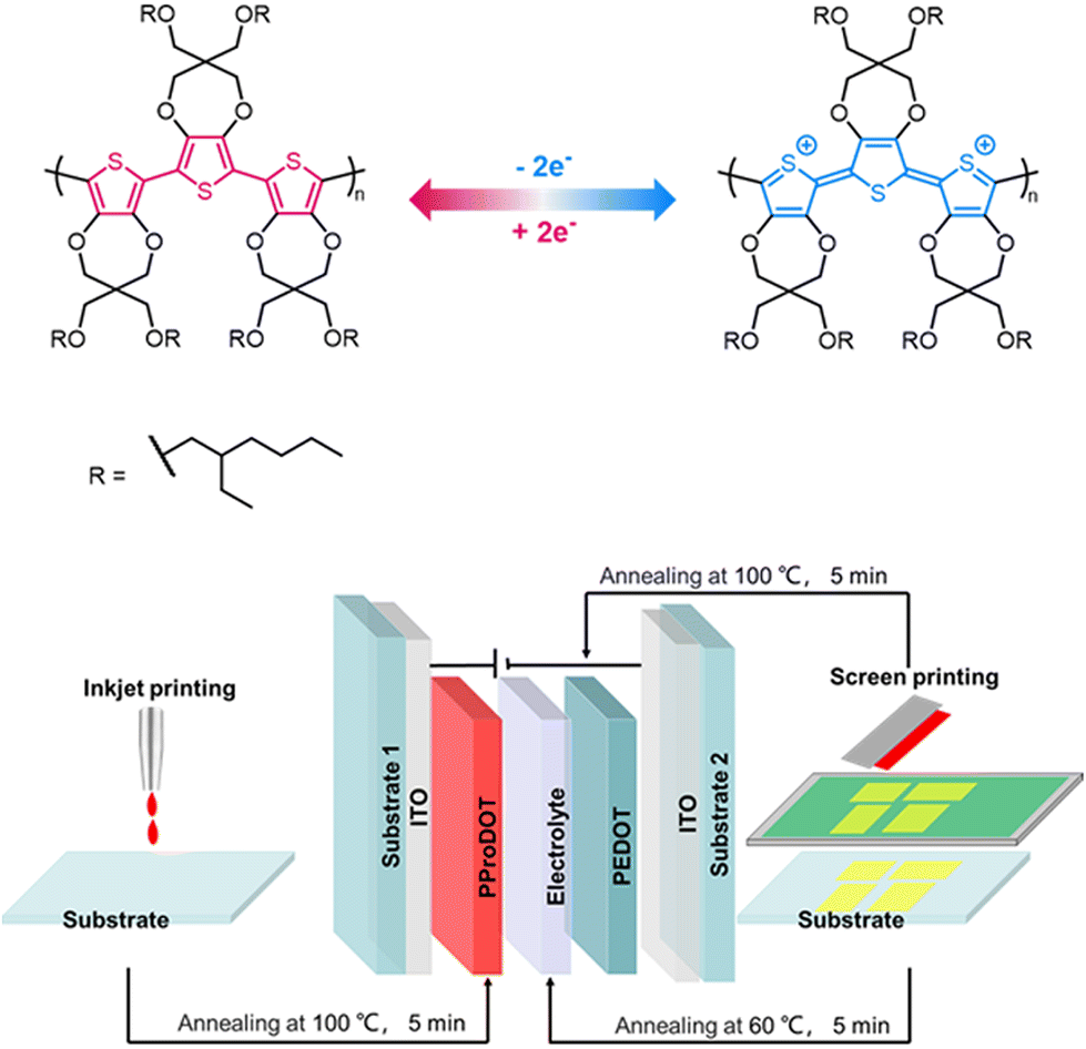 | ||
| Fig. 1 A diagrammatic sketch of the redox process (above). Schematic diagram of the structure and process of a full printed ECD (below). | ||
Screen printing of different compositions of electrolytes on a PET substrate was investigated. For electrolyte 1, PC and DI water were added for dissolving the LiTFSI and acting as the conduction medium for ion movement. PMMA32 was used to impede the outflow of the organic solvent, while PEG-DA was used for its ability to undergo UV cross-linking in the presence of a photoinitiator to form the solid gel matrix.33 By tuning the concentration of acetic ether, the viscosity of the electrolyte changed accordingly. Fig. 2a shows the data from the Kinexus rotating rheometer test. The viscosity of Electrolyte 2 is 88.2 Pa s. With the addition of a small amount of acetic ether in Electrolyte 1, its viscosity decreased to 5.0 Pa s, which substantially improved the penetration of the electrolyte in the nylon mesh of the screen printer and the quality of the screen-printed film. As for Electrolyte 3 it behaved similar to Electrolyte 2, exhibiting a poor screen printing result. The printed Electrolyte 1 on a PET substrate was not only of good film quality but also good flexibility, as shown in Fig. 2b. It retained good integrity after 100 bending tests at a radius of 5 mm.
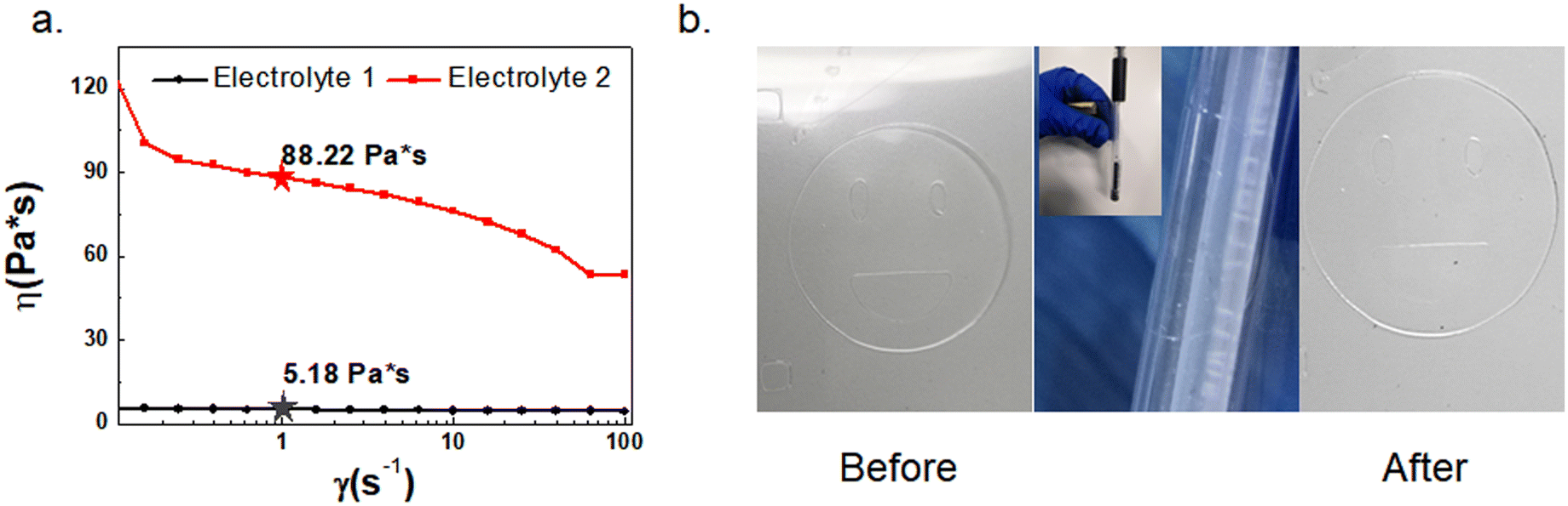 | ||
| Fig. 2 (a) Data of the rotating rheometer test; (b) digital photograph of the transparent electrolyte film pattern after bending 100 times with a bending radius of 0.5 cm. | ||
A working ECD requires both the cathode and anode in intimate contact with the electrolyte layer. For a blanketly coated electrolyte layer this would not be a problem as the uniform thickness of the electrolyte can be ensured. However, for a patterned electrolyte by screen printing this may not be the case as the electrolyte is no longer a continuous film but pixelated patterns. Different parts of the electrolyte may have different heights if the electrolyte does not have an appropriate viscosity for the screen-printed patterns to maintain their uniform thickness. For this reason, patterned electrolytes by screen printing were investigated. Fig. 3a shows the digital photographs of the screen printed 32 × 8 pixel array of electrolyte 1 on the PET substrate (the inset shows a schematic diagram of the amplification pixel array). Fig. 3b shows the optical microscopy image of a pixel after UV-curing. It maintained a proper shape, though there was a slope at the rim as the confocal laser scanning microscopy images show in Fig. 3c. The average thickness of 32 × 8 pixels is about 30 μm. In contrast, screen printing of electrolyte 2 or electrolyte 3 could not be performed as it was too viscous to print out any patterns. The above experiment indicates that the addition of acetic ether is critical to tuning the viscosity and facilitating the screen printing of the patterned electrolyte.
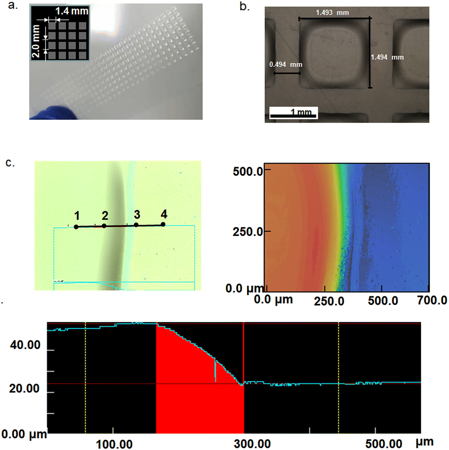 | ||
| Fig. 3 (a) Digital photograph of a pixel array of the screen-printed array on the PET substrate; the inset shows a schematic diagram of the amplification 32 × 8 pixel array; (b) the light-microscopy image of a pixel after UV-curing; and (c) the optical images of a pixel from a confocal laser scanning microscope. | ||
To further investigate the performance of ECDs with different formulations of the electrolyte, 4 types of devices were fabricated: D1 (without ethyl acetate): ITO/PEDOT/Electrolyte 2/PProDOT/ITO;
D2 (without ethyl acetate and water): ITO/PEDOT/Electrolyte 3/PProDOT/ITO;
D3 (without ethyl acetate): ITO/PProDOT/Electrolyte 2/ITO;
D4 (with ethyl acetate): ITO/PEDOT/Electrolyte 1 (annealing)/PProDOT/ITO.
In all the 4 devices, the PProDOT was spin-coated and the electrolytes were blade coated and their characterization results are shown in Fig. 4. D4 experienced an annealing process before assembling to remove ethyl acetate. Fig. S2† shows the cyclic voltammograms recorded with a scan rate of 50 mV s−1 for the 4 devices. The transmittance switching of the D1 and D4 devices showed a similar trend. Both D1 and D4 started bleaching around ∼0 V in a positive bias, indicating that ion insertion occurred, and reached the full color state at −0.2 V. Besides, D2 and D3 have small integrated absolute acreage compared with D1 and D4 corresponding to a poorer ion intercalation/deintercalation process under a low voltage. Fig. 4a shows the transmittance change of D1 vs. optical wavelength from −1.0 V to 1.0 V. The change was maximum at 550 nm; therefore it was chosen as the calibration wavelength, and the transmittance at the bleached state is denoted as Tb, whereas it is denoted as Tc for the colored state. Their difference is ΔT = Tb − Tc. The response time is the time taken for 90% of the complete optical switch to occur when square-wave potential pulses were applied to the working electrode.11Fig. 4b–e show the switching behaviors of D1–D4. Again, they indicate that D1 and D4 showed normal color switching behaviors while D2 and D3 did not, which agrees with the cyclic voltammograms shown in Fig. S2.† It can be seen from Fig. 4b and e that D1 and D4 required only 0.6 V of bleaching voltage and −0.5 V of coloring voltage and both had the response time around 1 s. As shown in Fig. S3,† both the thicknesses of PProDOT and PEDOT affected the optical modulation of the ECDs. The ∼160 nm PProDOT and ∼700 nm PEDOT showed the best optical modulation.
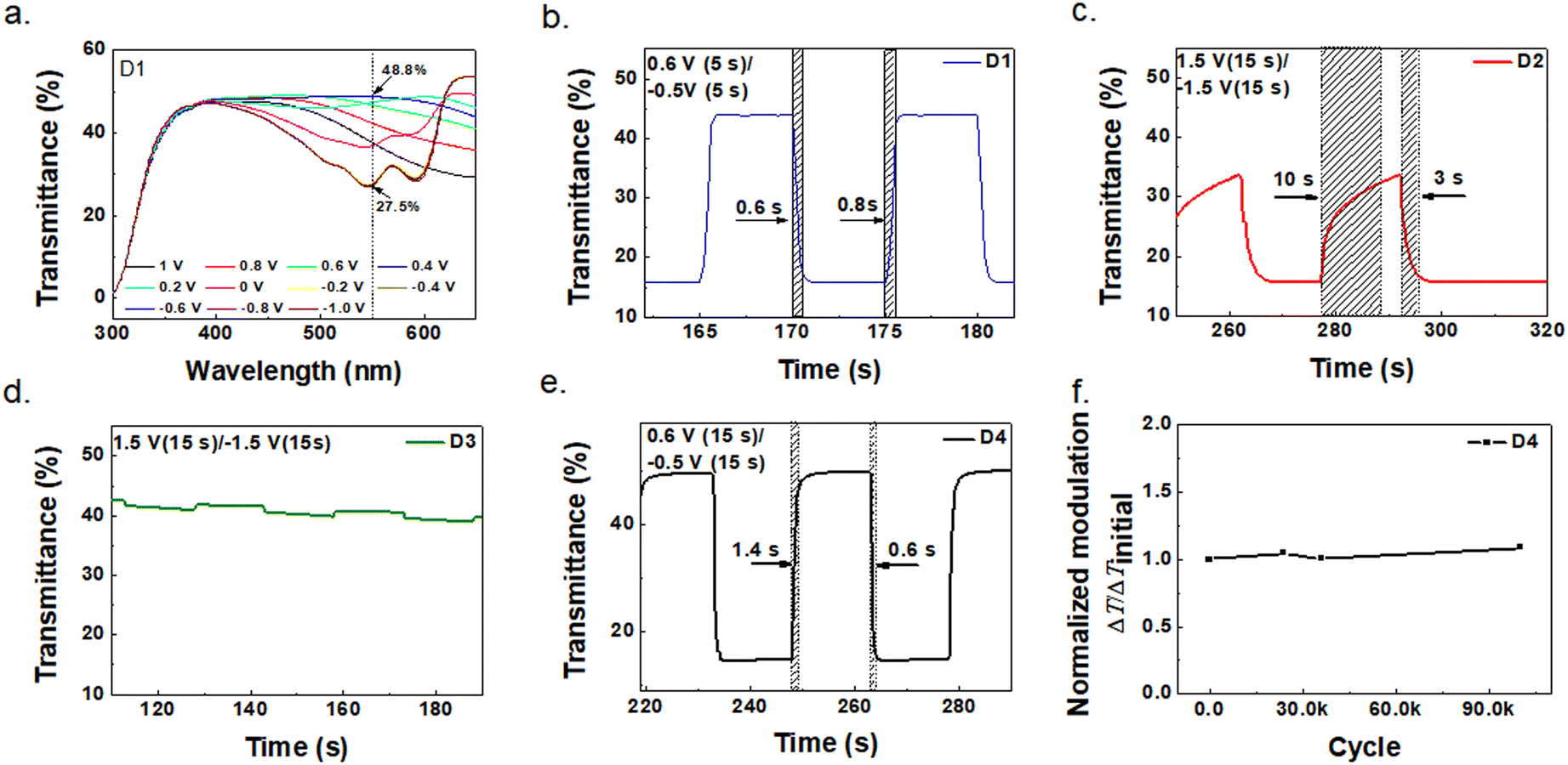 | ||
| Fig. 4 (a) Stepwise spectral change of D1 upon oxidation from −1.0 V to 1.0 V; (b)–(e) transmittance changes (ΔT, %) at 550 nm of D1–D4, respectively; and (f) optical modulation during 100 000 operating cycles of D4. | ||
To explain why D1 and D4 were substantially better than D2 and D3, one should look closely at the electrolytes used and the difference in device structures. Both D1 and D2 have identical device structures but different electrolytes, with electrolyte 2 in D1 having the ingredient of DI water and electrolyte 3 in D2 without DI water. Apparently, the presence of water greatly improves the device performance, which is consistent with the phenomenon in previous work that the ionic conductivity of aqueous electrolytes can be 2 orders of magnitude higher than that of organic electrolytes.26,28 For D1, D3 and D4, their electrolytes were added DI water. D3 had only ITO as the counter electrode, while D1 and D4 had added PEDOT to functionalize the ITO. The reason why D1 and D4 (Fig. 4b and e) were substantially better than D3 (Fig. 4d) is that the PEDOT counter electrode better matched with PProDOT than ITO.34 As for the influence of acetic ether (electrolyte 1 in D4 had it and electrolyte 2 in D3 did not have it), it only served to tune the viscosity of the electrolyte and subsequently evaporated during annealing, and therefore did not have any effect on the color switching characteristics. This was confirmed by the comparison of D1 and D4, as the electrolytes in them had one with acetic ether (electrolyte 1 in D4) and one without it (electrolyte 2 in D1). The investigation revealed that D4 had a combination of the best electrolyte and best device structure. Further cycling stability test on D4 was performed and it still maintained a ΔT of 35% at 550 nm even after 100000 cycles of color switching. The detailed transmittance changes between 0.6 V and −0.5 V over the 100000 cycles are listed in Fig. S4.†
Based on the aforementioned investigation, the ECD of D5 with a demo pattern was fabricated by screen printing of electrolyte 1 and PEDOT, as well as inkjet printing of PProDOT.
D5: (with ethyl acetate): ITO/PEDOT/Printed Electrolyte 1 (annealing)/PProDOT/ITO.
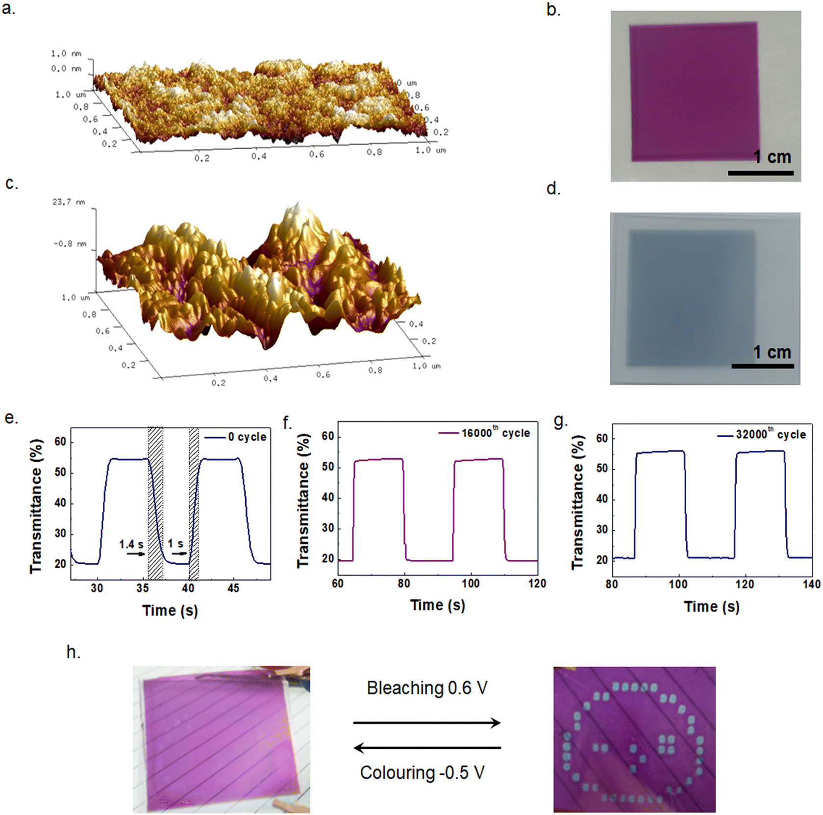
Electrolyte 1 was screen-printed on PEDOT and annealed. The two pieces were then assembled and cured by UV. The thickness of the printed PProDOT was ∼160 nm according to the Bruker step tester. The AFM image of the inkjet-printed PProDOT film is shown in Fig. 5a. The roughness of PProDOT is 0.28 nm, indicating a very flat film. Fig. 5b shows a digital photograph of printed PProDOT with a size of 20 mm × 20 mm. Fig. 5c shows the AFM image of screen-printed PEDOT, with a surface roughness of 6.61 nm. The rough surface of PEDOT was actually advantageous as it could increase the interface area with the electrolyte and facilitate the ion insertion to achieve fast response time. Fig. 5d shows a photograph of screen printed PEDOT with a thickness of ∼700 nm. Fig. 5e–g show the transmittances of D5 cycling between 0.6 V and −0.5 V at the initial state, 16000 and 32000 cycles, respectively, and the response times of bleaching (tb) and coloring (tc) are 1 s and 1.4 s, respectively. The ΔT at the initial state is 33.4%, similar to that of D4. Notably, the ΔT at 550 nm of D5 remained almost unchanged after 32000 cycles, which also shows good stability. The cyclic voltammograms of the D5 device are shown in Fig. S5.†Fig. 5h shows the color switching of D5 with a demo pattern. It exhibits a very clear change between the bleaching state and coloring state when voltages of 0.6 V and −0.5 V are applied. The performances of all the devices investigated in the present work (D1–D5) are summarized in Table 1. We list some of the work on thiophene derivatives in recent years, and ECDs based on our screen-printable electrolyte show the lowest driving voltage and fastest response from the comparison. These results manifest the great potential of the screen-printable electrolyte in solution-processed ECDs.
 | ||
| Fig. 5 (a) AFM image of inkjet printing of PProDOT; (b) digital image of a 20 mm × 20 mm PProDOT film on PET/ITO; (c) AFM image of screen printing of PEDOT; (d) digital image of a 20 mm × 20 mm PEDOT film on PET/ITO; (e)–(g) the changes in the transmittance with time upon potential switching between 0.6 V and −0.5 V of D5 at the initial, 16000th cycle and 32000th cycle; and (h) bleaching and coloring states of the fully printed patterned demo. | ||
| Ref. | Materials | Bleaching (V) | Coloration (V) | ΔTc | Response time (s) | ||
|---|---|---|---|---|---|---|---|
| ECa | CEb | Bleaching | Coloring | ||||
| a Electrochromic layer. b Counter electrode. c The optical contrast, ΔT, is the transmittance loss of the device between bleached and colored states. | |||||||
| D4 (this work) | PProDOT | PEDOT | 0.6 | −0.5 | 34.9% at 550 nm | 0.6 | 1.4 |
| D5 (this work) | PProDOT | PEDOT | 0.6 | −0.5 | 33.4% at 550 nm | 1.0 | 1.4 |
| 17 | PProDOT-Hx2 | PEDOT:PSS | 1.5 | −1.5 | — | 1.7 | 2.1 |
| 35 | ECP-Magenta | PEDOT:PSS | 1.0 | −0.5 | ∼40% at 550 nm | 21 | 4.4 |
| 35 | ECP-Magenta | PEDOT:PSS | 0.8 | −0.5 | ∼38% at 550 nm | 19 | 5.7 |
| 36 | PProDOT-Me2 | ITO | 1 | −1 | ∼49% at 582 nm | 2.0 | 1.6 |
| 37 | PProDOT-Me-2 | P(Cz4-co-CIn1) | 3.0 | −0.5 | 24.7% at 565 nm | 4.2 | 4.3 |
Conclusions
UV curable solid electrolytes have been developed, with lithium bis(trifluoromethane-sulfonyl) imide (LiTFSI) as the base electrolyte material and the addition of UV curable resin, DI water and ethyl acetate. It was found that DI water could substantially facilitate the ionic conductivity in the electrolyte and ethyl acetate could tune the viscosity of the electrolyte suitable for screen printing. A series of ECDs were fabricated and their performances were characterized and compared. With the optimized composition of the electrolyte and printing processes, an ECD with 0.6 V voltage/0.6 s bleaching time and −0.5 V voltage/1.4 s coloring time has been achieved. The ECDs also exhibited excellent stability, which could endure 100000 cycles of color switching while still maintaining 35% of transmittance change at a 550 nm wavelength. A demo ECD has been fabricated by inkjet printing of PProDOT and screen printing of both the electrolyte and PEDOT, exhibiting stable switching between the clear state and patterned color state.
Author contributions
All authors contributed to the experimental design; Chenchao Huang, Zishou Hu, Xinzhou Wu, and Xiaolian Chen performed the experimental work and analysed the data. Zheng Cui, Wenming Su, Xinzhou Wu, and Yuan-Qiu-Qiang Yi guided the project. Chenchao Huang wrote the first draft of the manuscript and all authors contributed to the finalization of the paper.Conflicts of interest
There are no conflicts to declare.Acknowledgements
This work was supported by the Natural Science Foundation of Jiangsu Province (BK20200258) and National Natural Science Foundation of China (No. 52103294). This work was also funded by the Jiangsu Funding Program for Excellent Postdoctoral Talent.References
- F. G. K. Baucke, Mater. Sci. Eng., B, 1991, 10, 285–292 CrossRef.
- Z. Wang, K. Shen, H. Xie, B. Xue, J. Zheng and C. Xu, Chem. Eng. J., 2021, 426, 131314 CrossRef CAS.
- P. Lei, J. Wang, P. Zhang, S. Liu, S. Zhang, Y. Gao, J. Tu and G. Cai, J. Mater. Chem. C, 2021, 9, 14378–14387 RSC.
- H. Li, L. McRae, C. J. Firby, M. Al-Hussein and A. Y. Elezzabi, Nano Energy, 2018, 47, 130–139 CrossRef CAS.
- L. Shao, X. Zhuo and J. Wang, Adv. Mater., 2018, 30, 1704338 CrossRef.
- P. Andersson Ersman, J. Kawahara and M. Berggren, Org. Electron., 2013, 14, 3371–3378 CrossRef CAS.
- W. Zhang, H. Li and A. Y. Elezzabi, Adv. Funct. Mater., 2022, 32, 2108341 CrossRef CAS.
- F. Li, Z.-J. Huang, Q.-H. Zhou, M.-Y. Pan, Q. Tang and C.-B. Gong, J. Mater. Chem. C, 2020, 8, 10031 RSC.
- K. Xiong, G. Emilsson, A. Maziz, X. Yang, L. Shao, E. W. H. Jager and A. B. Dahlin, Adv. Mater., 2016, 28, 9956–9960 CrossRef CAS PubMed.
- L. Hakola, E. Jansson, R. Futsch, T. Happonen, V. Thenot, G. Depres, A. Rougier and M. Smolander, Int. J. Adv. Manuf. Technol., 2021, 117, 2921–2934 CrossRef.
- G. Yang, Y.-M. Zhang, Y. Cai, B. Yang, C. Gu and S. X.-A. Zhang, Chem. Soc. Rev., 2020, 49, 8687–8720 RSC.
- J. Niu, Y. Wang, X. Zou, Y. Tan, C. Jia, X. Weng and L. Deng, Appl. Mater. Today, 2021, 24, 101073 CrossRef.
- D. Vernardou, K. Psifis, D. Louloudakis, G. Papadimitropoulos, D. Davazoglou, N. Katsarakis and E. Koudoumas, J. Electrochem. Soc., 2015, 162, H579–H582 CrossRef CAS.
- V. R. Buch, A. K. Chawla and S. K. Rawal, Mater. Today: Proc., 2016, 3, 1429–1437 Search PubMed.
- X. Li, K. Perera, J. He, A. Gumyusenge and J. Mei, J. Mater. Chem. C, 2019, 7, 12761–12789 RSC.
- A. M. Österholm, D. E. Shen, D. S. Gottfried and J. R. Reynolds, Adv. Mater. Technol., 2016, 1, 1600063 CrossRef.
- P. Tehrani, L.-O. Hennerdal, A. L. Dyer, J. R. Reynolds and M. Berggren, J. Mater. Chem., 2009, 19, 1799–1802 RSC.
- J. Chen, A. W. M. Tan, A. L.-S. Eh and P. S. Lee, Adv. Energy Sustainability Res., 2022, 3, 2100172 CrossRef.
- H. Li, J. Chen, M. Cui, G. Cai, A. L.-S. Eh, P. S. Lee, H. Wang, Q. Zhang and Y. Li, J. Mater. Chem. C, 2016, 4, 33–38 RSC.
- S.-I. Park, Y.-J. Quan, S.-H. Kim, H. Kim, S. Kim, D.-M. Chun, C. S. Lee, M. Taya, W.-S. Chu and S.-H. Ahn, Int. J. Precis. Eng. Manuf. - Green Technol., 2016, 3, 397–421 CrossRef.
- B. W.-C. Au and K.-Y. Chan, Polymer, 2022, 14, 2458 CAS.
- Y. Alesanco, A. Viñuales, J. Rodriguez and R. Tena-Zaera, Materials, 2018, 11, 414 CrossRef PubMed.
- J. Jensen and F. C. Krebs, Adv. Mater., 2014, 26, 7231–7234 CrossRef CAS PubMed.
- J. Wang, S. Xie, Q. Shi, H. Wang, H. Yang, S. Lin and M. Dai, Ceram. Int., 2022 DOI:10.1016/j.ceramint.2022.07.068.
- L. N. Sim, F. C. Sentanin, A. Pawlicka, R. Yahya and A. K. Arof, Electrochim. Acta, 2017, 229, 22–30 CrossRef CAS.
- W. Tang, Y. Zhu, Y. Hou, L. Liu, Y. Wu, K. P. Loh, H. Zhang and K. Zhu, Energy Environ. Sci., 2013, 6, 2093–2104 RSC.
- H. Kim, J. Hong, K.-Y. Park, H. Kim, S.-W. Kim and K. Kang, Chem. Rev., 2014, 114, 11788–11827 CrossRef CAS PubMed.
- S. Chen, M. Zhang, P. Zou, B. Sun and S. Tao, Energy Environ. Sci., 2022, 15, 1805–1839 RSC.
- L. Zhan, Z. Song, J. Zhang, J. Tang, H. Zhan, Y. Zhou and C. Zhan, Electrochim. Acta, 2008, 53, 8319–8323 CrossRef CAS.
- L. Niu, C. Kvarnström and A. Ivaska, J. Electroanal. Chem., 2004, 569, 151–160 CrossRef CAS.
- L. Zhou, M. Yu, X. Chen, S. Nie, W.-Y. Lai, W. Su, Z. Cui and W. Huang, Adv. Funct. Mater., 2018, 28, 1705955 CrossRef.
- D. S. Kim, H. Park, S. Y. Hong, J. Yun, G. Lee, J. H. Lee, L. Sun, G. Zi and J. S. Ha, Appl. Surf. Sci., 2019, 471, 300–308 CrossRef CAS.
- Y. Zhu, M. T. Otley, F. A. Alamer, A. Kumar, X. Zhang, D. M. D. Mamangun, M. Li, B. G. Arden and G. A. Sotzing, Org. Electron., 2014, 15, 1378–1386 CrossRef CAS.
- D. Eric Shen, A. M. Österholm and J. R. Reynolds, J. Mater. Chem. C, 2015, 3, 9715–9725 RSC.
- A. W. Lang, Y. Li, M. De Keersmaecker, D. E. Shen, A. M. Österholm, L. Berglund and J. R. Reynolds, ChemSusChem, 2018, 11, 854–863 CrossRef CAS.
- Q. Chen, Y. Shi, K. Sheng, J. Zheng and C. Xu, ACS Appl. Mater. Interfaces, 2021, 13, 56544–56553 CrossRef CAS PubMed.
- C.-W. Kuo, T.-H. Hsieh, C.-K. Hsieh, J.-W. Liao and T.-Y. Wu, J. Electrochem. Soc., 2014, 161, D782–D790 CrossRef CAS.
Footnote |
| † Electronic supplementary information (ESI) available. See DOI: https://doi.org/10.1039/d2nr03209k |
| This journal is © The Royal Society of Chemistry 2022 |