
Electro-vibrational coupling effects on “intrinsic friction” in transition metal dichalcogenides†
Antonio Cammarata *a and
Tomas Polcarab
*a and
Tomas Polcarab
aDepartment of Control Engineering, Czech Technical University in Prague, Technicka 2, 16627 Prague 6, Czech Republic. E-mail: cammaant@fel.cvut.cz; Fax: +420 224 91 8646; Tel: +420 224 35 7598
bnCATS, FEE, University of Southampton, SO17 1BJ Southampton, UK
First published on 7th December 2015
Abstract
We propose a protocol to disentangle the electro-vibrational structural coupling contributing to the intrinsic tribologic properties of layered MX2 transition metal dichalcogenides (M = Mo, W; X = S, Se, Te) under load. We employ ab initio techniques to model how changing the interlayer distance affects the electronic distribution and the vibrational properties of the system. We analyze the electro-vibrational coupling features by combining orbital polarization and mode Grüneisen parameters analyses with the recently developed bond covalency descriptor and the lattice dynamic metric named cophonicity. We find that intralayer charge distribution depends on the interlayer distance, determining, in turn, a shift of specific vibrational frequencies. We finally suggest a route to control the frequency shift, thus the bulk response to the load, in transition metal dichalcogenides through a proper selection of the atomic type.
1 Introduction
Transition metal dichalcogenides (TMDs) are van der Waals structures with general MX2 stoichiometry (M = transition metal cation, X = chalcogen anion); they have attracted great interests because of their close features with graphene and their highly versatile stoichiometry.1 They find tribologic applications whereas liquid lubricants cannot be used, such as in extreme temperature-pressure conditions or possibility to be expelled from the gaps separating moving parts in a device. Numerous studies have dealt mainly with the electronic properties;2–4 indeed, only few theoretical works investigated on the tribologic aspects,5–9 and, to the best of our knowledge, there are no theoretical studies about the electron–phonon coupling effects on the frictional properties. Tribological properties are usually modeled at the atomic scale by molecular dynamics simulations, the results of which, unfortunately, can hardly be transfered across the chemical compositions, since they rely on mathematical expressions of atomic interactions calibrated ad hoc on the studied system. Quantum mechanical approaches have also been used to this aim,10 focusing on a specific stoichiometry and chemical composition.Theoretical works have had the role to model specific tribologic materials, while experimental data has been so far the guide to select the proper stoichiometry, chemical composition and geometry of the system to design a TMD compound with improved frictional properties. A broader theoretical approach encompassing all the compositions of the TMDs family would help to narrow the experimental exploration to only those materials that are promising candidates. In this perspective, we now want to go beyond the construction of models that explain the experimental data, and will thus formulate new guidelines to design novel tribologic materials.
In a previous computational investigation,11 we understood that the dynamic properties of the MX2 compounds can be tuned by proper adjustment of M–X bond covalency, structural distortions, and M/X atomic participation to the vibrational properties of the system with no applied load. We then found a route to select the proper atomic species and geometry; we thus individuated Ti as optimal substituent for Mo in MoS2 and suggested a new Ti-doped MoS2 phase as promising tribological material.
Indeed, substitution of Mo in MoS2 with Nb,12 Cr,13 Mn14 and Ti15 have been recently reported, showing that transition metal doping in the Mo crystallographic site is quite common practice and is experimentally feasible. We now study the coupling of the electronic and dynamic properties in the presence of external load; in particular, we want to understand how to control the dynamic features of the system via a fine control of the electronic structure. The mechanism governing such coupling would also contribute to the comprehension of the strain-induced shifts of the Raman-active modes observed in TMDs under uniaxial strain.16–18
In the present work, we study the intrinsic friction in MX2 TMDs in the presence of external load. The term microscopic friction refers to the friction generated by the relative motion of few adjacent atom layers; it is the result of the local electronic and structural features of the material at the atomic level, originating from the atomic type and the geometric arrangement of the atoms. When microscopic friction involves only atomic layers of the bulk structure with no structural irregularities (dislocations, layer truncations etc.), we can name it as intrinsic friction, since it can be considered as a property peculiar of the pure compound without imperfections. In consequence, all tribological properties originating from intrinsic friction, will be referred as intrinsic of the considered system. The knowledge of the intrinsic tribological properties is nowadays becoming mandatory with the advance of the experimental techniques, now capable to micromanipulate free-standing atomic layers.19
We here propose a protocol to disentangle the electro-vibrational coupling contributions to the atomic motions that may facilitate interlayer slip, hence affecting intrinsic friction. Thanks to its universal applicability, our approach can be promptly exploited to engineer the lattice dynamic properties and the electronic distribution in materials for diverse applications other than tribology, like in optical or electronic devices. We also extend the present analysis to the specific Ti-doped MoS2 phase that we already identified as promising TMD-based candidate. To this aim, we will disentangle the electronic from the structural features of MX2 TMDs that determine the bulk contribution to intrinsic friction at the quantum mechanical level, using density functional theory based techniques. We will exploit the recently developed lattice dynamics descriptor, named cophonicity,11 to capture how each atomic species contributes to a specific vibrational band (see ESI†). With such descriptor, we are able to disentangle the atomic electro-structural contributions to the lattice vibrations affecting the layer sliding. Our approach enables us to capture the electronic and geometric features that are common to the MX2 systems and responsible of the intrinsic frictional properties under external load. Finally, we suggest a route to select and modify the MX2 stoichiometry and geometry to obtain TMD compounds with improved intrinsic tribological response under load.
2 Methods
MX2 transition metal dichalcogenides are formed by layers coupled by weak van der Waals forces that allow relative sliding under tribological conditions. Each layer is formed by hexagonally packed metal atoms (M) forming covalent bonds with six chalcogen anions (X) in a trigonal prismatic coordination (Fig. 1). Several stable TMDs polymorphs and polytypes are found,1 some transforming into each other by sliding of subsequent layers. Sliding motions include reorientations of one layer with respect to its two adjacent ones by means of rotations about an orthogonal axis. The complex atomic displacements that result into layer sliding, either commensurate or not, can be represented as linear combinations of displacement patterns, e.g. vibrational modes, of two adjacent layers of the most stable configuration. We focus on model systems with two layers in the unit cell and we choose 2H polymorph crystalline MX2 structures as model geometries, with M = Mo, W and X = S, Se, Te, and hexagonal P63/mmc symmetry (SG 194); for simplicity, we will refer to them as MX by dropping the stoichiometric coefficients. We choose the 2H configuration in which two adjacent layers are oriented in such a way that an M atom of one layer is aligned with two X atoms of the other one along the direction orthogonal to each layer (c-axis in our setting—see Fig. 1a); we make this choice following the outcomes of a recent ab initio study on the MoS2 compound:10 in this, authors show that this configuration is the most stable one among those considering several arrangements of two subsequent MoS2 layers. We also consider the MoS optimized structure and we substitute a Mo atom with one Ti atom in such a way that, within a single layer, its first neighbouring cation shell is formed only by Mo atoms, building the Mo3Ti1S8 (Ti:MoS) system with orthorhombic Cmcm (SG 63) symmetry (Fig. 1b).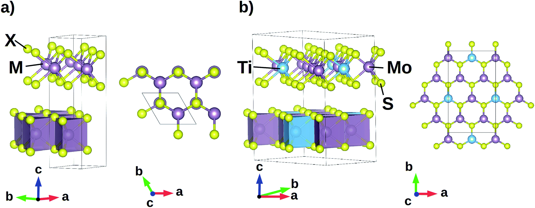 | ||
| Fig. 1 (a) Hexagonal P63/mmc structure of 2H polymorph MX2 model geometries (M = transition metal, X = chalcogen atom); M–X bonds are arranged in a trigonal prismatic coordination forming MX2 layers that can slide thanks to weak van der Waals interactions. (b) Orthorhombic Cmcm Ti:MoS2 model system: within each layer, one Ti atom is surrounded by only Mo atoms in the first neighbouring cation shell. | ||
Our calculations are performed on 2 × 2 × 2 supercells of the MX2 and Mo3Ti1S8 unit cells, within the framework of the density functional theory (DFT), using the projector-augmented wave (PAW) formalism and the Perdew–Burke–Ernzerhof (PBE) energy functional20 with van der Waals correction as implemented in VASP.21 We paid particular attention to the choice of the description of the van der Waals interactions, since it is recognized they play an important role in determining the static and dynamic properties of TMDs;22 after preliminary benchmarks, we chose the Grimme correction,23 that is able to capture the structural features. The Brillouin zone is sampled with a minimum of a 5 × 5 × 3 k-point mesh and plane wave cutoff of 550 eV. Full structural (atoms and lattice) relaxations are initiated from diffraction data24–29 and the forces minimized to a 0.5 meV Å−1 tolerance. We computed the phonon band structure and the mode Grüneisen parameters of each considered system with the aid of the phonopy software.30
3 Results and discussion
We are here interested into the dynamic response of the bulk in the presence of external load. We are going to focus on the atomic motions that affect a global slide of adjacent layers, in order to study the intrinsic friction of the systems. Such motions can be represented by means of linear combinations of vibrational modes, each having an associated vibrational frequency that depends on the atomic species; the lower is the frequency, the easier the sliding motion can be promoted. In terms of the classical picture, we understand this by recalling that the frequency represents the curvature of the system energy hypersurface as a function of the atomic coordinates. At a constant energy of the system, the lower is the frequency of a mode, the higher is the amplitude of the corresponding atomic displacements; if such displacements are associated to layer sliding, higher amplitudes correspond to enhanced shift of one layer with respect to its adjacent ones, hence promoting the sliding of the layers. The study of how the mode frequencies change at different external load and what is the role of electro-vibrational coupling tells us how the bulk contributions to the macroscopic frictional properties are affected; at the same time, we will learn how to tune such contributions, in order to design new TMDs with enhanced frictional response.We first relax the system geometries and compute the corresponding phonon band structure along a standard31 linear path joining the high-symmetry points of the irreducible Brillouin zone (IBZ); we do not find unstable displacements, confirming that atomic positions are in a stable configuration. We label phonon bands with progressive integer numbers according to standard convention, starting from the lowest associated frequency. In such description, Γ(1) represents the vibrational mode relative to the band number 1, that is the displacive mode associated to the lowest frequency ω(Γ)1 at the Γ point of the IBZ; analogously, Γ(2) is associated to the vibrational mode with frequency ω(Γ)2 such that ω(Γ)3 ≥ ω(Γ)2 ≥ ω(Γ)1 and so on. We here recall that degeneracy of vibrational modes in MoS system is partially lifted in Ti:MoS model, having the latter a lower number of symmetries. According to the displacement patterns, A(1–4) degenerate modes of MX systems correspond to Z(1–2) and Z(3–4) degenerate modes of Ti:MoS model, respectively, while A(5–6) degenerate modes correspond to Z(5–6) degenerate modes, respectively; however, for brevity, we will still call the Z(1–6) modes as A(1–6), without affecting the clarity of our discussion.
The presence of external load determines a change in the volume of the unit cell. To study how the load affects the mode frequency, we start by computing the mode Grüneisen parameters γi(![[q with combining right harpoon above (vector)]](https://www.rsc.org/images/entities/i_char_0071_20d1.gif) ) for each i-th mode at each point of the selected IBZ path; γi() is defined as
) for each i-th mode at each point of the selected IBZ path; γi() is defined as
 | (1) |
changes with the volume V of the unit cell. We find that the γi() amplitudes are highest for ω(Γ)4–6 and ω(A)1–6 (Table 1), while all the remaining mode frequencies show |γi()| ≃ 1. This means that the modes that are mostly affected by a change of the unit cell volumes are: (i) the degenerate Γ(4–5) modes, corresponding to rigid layer sliding in the ab-plane (Fig. 2a), (ii) Γ(6), representing a rigid layer shift along the c-axis that changes the interlayer distance (Fig. 2b), (iii) the degenerate A(1–4) modes, producing layer sliding in the ab-plane accompanied by asymmetric stretching of the X–M–X bond, maintaining constant the interlayer distance (Fig. 2c), (iv) the degenerate A(5–6) modes, corresponding to a change of the interlayer distance and a flattening of the MX6 polyhedra (Fig. 2d). We will focus our discussion only on the modes that we just described since all the remaining modes are less affected by a change in the unit cell volume, hence preserving the characteristic frequencies in the presence of external load.
) of the ω4–5(Γ), ω6(Γ), ω1–4(A) and ω5–6(A) mode frequencies, and Cph(M–X) cophonicity (cm−1) of the M–X atomic pair of the MX and Ti:MoS systems
| System | γ4–5(Γ) | γ6(Γ) | γ1–4(A) | γ5–6(A) | Cph(M–X) |
|---|---|---|---|---|---|
| a Z(1–6) modes of Ti:MoS model correspond to A(1–6) modes of MX systems.b Global cophonicity of Ti:MoS system calculated as weighted average of the Cph(Mo–S) and Cph(Ti–S) cophonicities, with weights corresponding to the M stoichiometric coefficients. | |||||
| MoS | 3.7 | 5.3 | 2.6 | 4.9 | 0.00 |
| MoSe | 4.1 | 5.1 | 4.4 | 4.9 | −0.39 |
| MoTe | 3.0 | 3.9 | 3.4 | 3.7 | −0.75 |
| WS | 3.9 | 5.7 | 3.0 | 5.6 | 0.26 |
| WSe | 4.1 | 5.3 | 3.7 | 5.2 | 0.10 |
| WTe | 4.9 | 9.3 | 4.9 | 9.2 | −0.36 |
| Ti:MoS | 5.5 | 8.7 | 5.9a | 8.3a | −0.17b |
 | ||
| Fig. 2 Schematics of the modes with the highest associated mode Grüneisen parameters: (a) rigid layer sliding in the ab-plane; (b) rigid layer shift along the c-axis producing a variable interlayer distance; (c) layer sliding in the ab-plane and asymmetric stretching of the X–M–X bond; (d) variable interlayer distance accompanied by a flattening of the MX6 polyhedra. Color code for atoms is the same as in Fig. 1. | ||
We now want to relate the stability of the mode frequency to the chemical composition. We consider the phonon density of states of the relaxed systems and evaluate the cophonicity of the M–X atomic pair (Table 1) in the frequency range [0, 70] cm−1; we choose such range to be the same for all the systems because the frequencies of the modes we are focusing on fall within such integration range, irrespective of the considered chemical composition. We then relate the M–X pair cophonicity to the mode Grüneisen parameters. We find that, for rigid layer sliding (Γ(4–5)) or for those modes involving interlayer distance variation (Γ(6), A(5–6)), γi() is the lowest when the lowest cophonicity is realized (MoTe system); this tells us that such modes are less affected by a change in the unit cell volume if the M and X atoms contributions to the corresponding energy band show the lowest mixing. The A(1–4) modes, instead, turn out to be more stable against volume variations when the M and X atoms equally contribute to the corresponding frequency, hence realizing Cph(M–X) ≈ 0 (MoS system). Based on these results, among the explored chemistries, the dynamic bulk features of the MoTe system are the most stable ones against unit cell volume variations.
The evaluation of the mode Grüneisen parameters is done within the approximation of isotropic variations of the relaxed volume. However, thanks to the presence of interlayer gaps determining the layered structure of the studied TMDs, the X–X distances across the gap can be affected more easily than the intralayer atomic spacing, where stronger atomic bonds make the M–X coordination more rigid. For this reason, in tribological conditions, external load applied along the c-axis affects mainly the interlayer distances, hence producing a non-isotropic change in the unit cell volume. We therefore choose to extend our mode Grüneisen analysis to specific anisotropic variations of the volume, in order to focus on the structural response in the presence of external load. We want to compare the results at particular structure configurations; for this reason, instead of fixing the value of the load along the c-axis, we will model the presence of load in this way: starting from the relaxed structures, we will build new model systems by rigidly shifting two subsequent MX2 layers to vary the interlayer distance d0; calling δIL the difference d − d0, where d is the distance after the rigid shift, we build 6 model geometries for each of the considered system by setting δIL = ±0.5, ±1.0 and ±1.5 Å, respectively. With this choice, a negative value of δIL represents a compression along the c-axis, which is typical for sliding of perfect crystal or TMD 2D sheets. However, topographic features can locally cause decrease in contact pressure to zero (i.e. δIL = 0) or even separate two layers at the sliding interface (Fig. 3a). Such scenario occurs when TMD sheets are bended during sliding, as illustrated in Fig. 3b. It is worthy to note here that, in our simulations, δIL = −1.5 Å correspond to an external pressure greater than 80 GPa for all the considered chemistries. We are aware that an isostructural phase transition from 2Hc to 2Ha polytype is observed for MoS2 between 20 and 29 GPa;32–34 on the other hand, experiments performed in the presence of high pressure have been reported only for few of the considered systems other than MoS2, and no phase transitions have been found for them nor are expected.35,36 For this reason, to make a complete comparison at different δIL among the calculated quantities of all the systems, we do not consider the MoS2 phase transition at high pressure.
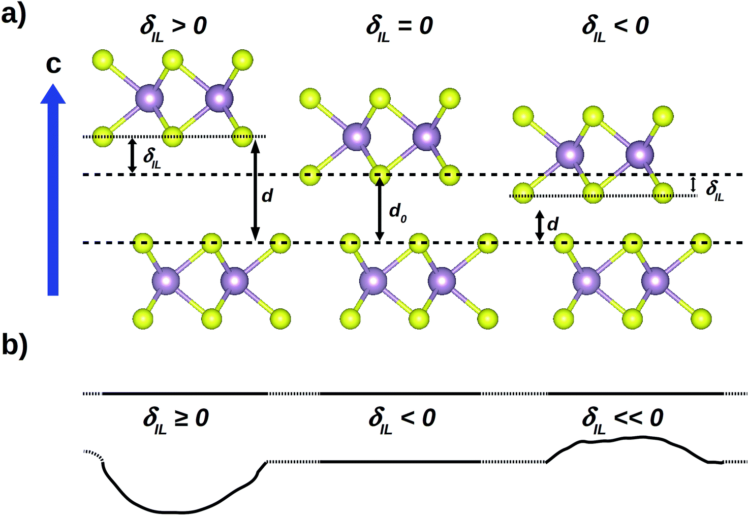 | ||
| Fig. 3 (a) The presence of external load is modeled starting from the relaxed structure and changing the optimized interlayer distance d0 to a new value d by shifting one layer of a quantity equal to δIL along the c-axis. (b) On a larger scale, positive and negative δIL values represent deviations from the parallel layer ideal configuration, due to the presence of topographic defects. | ||
We then analyze the variation of ω(Γ)4–6 and ω(A)1–6 with δIL (Fig. 4). Irrespective of the atomic types, increasing the interlayer distance (δIL > 0) reduces the vibrational frequencies, tending to similar asymptotic values. This is an expected result because the displacement patterns of the considered modes involve interlayer interactions that depend on the specific atomic type; at high δIL values, such interactions tend to vanish and the relative position of the layers does not affect the intralayer atomic motions. On the other hand, negative δIL values increase ω, reducing the population of the corresponding modes at fixed system energy, hence disfavoring the corresponding displacement patterns, with exceptions at δIL = −1.5 Å, where some instabilities arise. The origin of such exceptions could be sought in the peculiar accommodation of the electronic cloud due to the highly reduced interlayer distance; this requires a more detailed study of the electro-structural coupling, but is out of the scope of the present work. Specifically, we find that decreasing the interlayer distance d reduces the population of: (i) the sliding modes Γ(4–5) and A(1–4), reducing the bulk contribution to the layer sliding; (ii) the modes that change the interlayer distance d, making the bulk less prone to a further compression along the c-axis.
 | ||
| Fig. 4 Frequencies of Γ(4–6) and A(1–6) modes as a function of the interlayer distance variation δIL. Irrespective of the M and X atomic types, increasing the interlayer distance lowers the vibrational frequencies, while increasing the load is expected to disfavor sliding, with exceptions at δIL = −1.5 Å. | ||
To understand how the vibrational frequencies variation is coupled to the electronic structure, we now focus on the electronic density distribution. We start by evaluating the evolution of the atomic charge with δIL using two approaches: Bader analysis,37 based on zero flux surfaces, and integration of the atom-site projected electronic density of states up to the Fermi level. Comparing the two methods helps us to address the ambiguity in assigning charges to atoms. Interestingly, both methods point at same conclusions. No charge variation is found for Ti atom in the entire δIL range; indeed, irrespective of the composition, at decreasing δIL, we observe an increase of the Mo or W atomic charge at the expenses of the X anion, indicative of charge transfer from X to M ion. To better understand how the electronic charge is rearranged after variations of the interlayer distance, we measure the orbital polarization38,39 of the X and M atomic species as a function of δIL. Let's recall here that the orbital polarization ![[scr P, script letter P]](https://www.rsc.org/images/entities/char_e52f.gif) of ml1 orbital relative to ml2 orbital is defined as
of ml1 orbital relative to ml2 orbital is defined as
 | (2) |
px–py, px–pz and py–pz of the X atom, t2g–eg and  of Mo and W cations, d–s and d–p of the Ti atom in the Ti:MoS model. Irrespective of the chemical composition, positive values of δIL do not affect any orbital population in a significant way; moreover, orbital polarization of the Ti atom are nearly constant within the considered δIL range, their average values d–s = 85.1% and d–p = 77.2% changing about 1%. Increasing the load (δIL < 0), we observe that: (i) X px and py population are almost unvaried while pz orbital population decreases (Fig. 5a–c), (ii) M eg orbital population increases (Fig. 5d) and (iii) M dz2 population increases at the expenses of dx2−z2 (Fig. 5e). This indicates that reducing the interlayer distance induces flow of charge from the interlayer region, described by the pz orbitals, towards the intralayer region. Charge tends to accumulate on each M atom, in particular along an axis orthogonal to the plane containing the M atoms belonging to the same MX2 layer (Fig. 6). We can then conclude that interactions among layers are mediated by the pz orbitals of X anions belonging to two adjacent layers and facing the same interlayer region. Finally, we can argue that the charge distribution in the inner part of each layer can be controlled by proper perturbations of the electronic density at the surface of the layer.
 | ||
Fig. 5 Orbital polarization of MX and Ti:MoS systems as a function of δIL: (a) X px–py, (b) X px–pz, (c) X py–pz, (d) M t2g–eg, (e) M  ; M = Mo for the data relative to the Ti:MoS system in panels (d) and (e). Reducing the interlayer distance induces charge accumulation towards the intralayer region, along an axis orthogonal to the plain containing the M atoms belonging to the same MX2 layer. ; M = Mo for the data relative to the Ti:MoS system in panels (d) and (e). Reducing the interlayer distance induces charge accumulation towards the intralayer region, along an axis orthogonal to the plain containing the M atoms belonging to the same MX2 layer. | ||
 | ||
| Fig. 6 Schematic representations of the charge density and the inter-to-intralayer charge flow mechanism: RGB gradient indicates decreasing charge density (red = highest, blue = lowest) while shaded atoms and bonds are out of the sections showing the charge distribution. Color code for atoms is the same as in Fig. 1; the generic M cation here represents Mo or W atom, since no variation of the orbital polarization of Ti atom has been observed in the Ti:MoS system. (a) Electronic density on a plane parallel to the c-axis and containing two X–M–X bonds, each belonging to two subsequent MX2 layers. Upon interlayer distance reduction, charge flows from the inter- to the intralayer region, thanks to electron transfer from X pz orbital to M eg orbital via an intermediate step involving the px and py orbitals of the X atom; charge thus accumulates onto an axis containing the M cation and orthogonal to the layers. (b) Electronic charge distribution on a plane orthogonal to the c axis and containing the X anions facing the same interlayer region. The hybridization of the dz2 orbital of the M cation with the px and py orbitals of the X atom allows the X → M charge transfer. | ||
Orbital polarization is a fine partition of the electronic density, providing a real-space picture of the charge redistribution after alteration of the system geometry in the presence of external load. However, to understand how the redistribution of the electronic charge affects the atomic motions (electro-vibrational coupling), we need to recollect the fragmented information provided by the orbital polarization into a simple electronic descriptor. To this aim, we now analyse the CM,X M–X bond covalency at each of the considered δIL values, making use of the bond covalency metric that has already been defined by means of atomic orbital contributions to the electronic density of states.40 M–X bond covalency is determined by the cooperative effect of the electronic structure of the M and X atoms and the structural distortions of the system, as it has already been observed in a theoretical study on perovskite oxides,40 optically active telluro-molybdates41 and tribologic TMD materials.11 We evaluate CM,X as a function of δIL by considering the energy range [−10.0, 0.0] eV, corresponding to the electronic valence band, where the Fermi level has been set to 0.0 eV (Fig. 7a). In the first instance, we note that, for δ ≥ 0.0 Å, M–X bond covalency can be considered as constant; this result is difficult to extrapolate from the orbital polarizations due to the fluctuations found in the same δIL range (Fig. 5), and shows how the covalency metric CM,X acts as a collective descriptor of the details of the electronic structure. As we already observed about the mode frequencies, the constant trend of CM,X for δ > 0 can be explained considering that at high interlayer distances only intralayer interactions are relevant, and they are the only ones that determine the electronic distribution. On the other hand, irrespective of the chemical composition, we find that M–X covalency is monotonically decreasing with increasing load. We understand this in this way: the charge accumulation in the intralayer region increases the electronic repulsion due to the Pauli's exclusion principle, inducing a localization of the electronic charge onto the M cation, making the M–X bond more ionic. Such charge localization, and the consequent reduction of M–X bond covalency, is responsible of the hardening of the Γ(4–6) and A(1–6) modes; this means that the less covalent the M–X bond is, the less favorable the bulk contribution is to the layer shift along the c-axis (Γ(6) and A(5–6) modes) and to the layer sliding (Γ(4–5) and A(1–4) modes). This last aspect suggests that, at increasing load, the macroscopic friction coefficient is expected to increase; exceptions are found for those systems with instabilities at δIL = −1.5 Å, which, at very high loads, are expected to show improved frictional properties.
 | ||
| Fig. 7 (a) M–X bond covalency and (b) M–X pair cophonicity as a function of the interlayer distance variation δIL; covalency is found to be a monotonic function of δIL while cophonicity is nearly constant for δIL ≥ −1.0 Å. (c) Amplitude of the variation interval of Γ(4–6) and A(1–6) mode frequencies as a function of Cph(M–X); Cph(M–X) values here used are those calculated at δIL = 0.0 Å. The smallest variation interval of the considered frequencies is realized at Cph(M–X) = −0.36 cm−1, corresponding to the WTe system. | ||
So far we have shown that the frequencies of those modes that are mainly affected by a change in the unit cell volume, e.g. Γ(4–6) and A(1–6) modes, generally increase at increasing external load (δIL < 0); we found some exceptions that are expected to have bulk contributions favoring the layer sliding at high load (δIL = −1.5 Å). We explained the hardening of the modes in terms of localization of the electronic density on the M cation and a consequent reduced M–X bond covalency; the latter turned out to be a convenient descriptor to understand the origin of the vibrational behavior of the system in the presence of external load. To further disentangle the atomic contributions to the vibrational response, we now calculate the M–X pair cophonicity at the considered δIL values, in order to understand how the relative M/X atomic contribution to the vibrational bands is affected by the interlayer distance (Fig. 7b). Interestingly, we find an abrupt variation of Cph(M–X) at δIL = −1.5 Å, supporting the idea that significant electro-structural coupling effects arise at high load; on the other hand, irrespective of the atomic types, Cph(M–X) can be considered constant for δIL ≥ −1.0 Å. This last result tells us that once the chemical composition and the M–X connectivity are fixed, M–X pair cophonicity is a feature of the MX and Ti:MoS systems, that is preserved if the external load is not extremely high. We can therefore use the M–X cophonicity calculated at zero load to characterize the system and its response under load.
The variability of the structural response can be quantified in terms of the amplitude of the interval within which each mode frequency changes: the higher is such amplitude, the higher is the variation of a specific frequency with the external load. We define the variation amplitude Δω() of the frequency ω associated to the point of the IBZ as
 | (3) |
 and
and  are the highest and the lowest frequency ω at fixed point of the IBZ. The smaller Δω() is, the smaller the variation amplitude of the vibrational frequency is; a system with small Δω() shows bulk properties that are less affected by the external load. We calculate Δω for the Γ(4–5), Γ(6), A(1–4) and A(5–6) modes, respectively. The variability of the structural response is strictly connected to the chemical composition; we then connect the frequency variation amplitude to the M–X cophonicity by evaluating Δω for δ ∈ [−1.0, 1.5] Å, where Cph(M–X) can be considered constant. We find that, irrespective of the mode, the minimum Δω is realized at Cph(M–X) = −0.36 cm−1, corresponding to the WTe system (Fig. 7b). Moreover, concerning the Γ(4–5) and A(1–4) sliding modes, Ti:MoS system shows a small Δω value similarly to WTe. These outcomes suggest that, in the presence of external load, the Ti:MoS and WTe bulk contributions to the sliding are expected to be the least affected among the studied systems. We here note that in our previous study on MX2 TMDs,11 we already discussed how, in absence of load, the Ti:MoS bulk contribution to the macroscopic friction is expected to be the same as that of WTe compound.
We want to know how to tune Δω in order to determine how prone the material is to change its response under load; to this aim, we prefer to rely on properties that are characteristic of the system with no load, in order to reduce the number of parameters to consider to build our models. We showed how the variation of the frequencies, those associated to the modes mostly affected by unit cell volume changes, is due to charge flow between the interlayer and intralayer region, induced by variations of the interlayer distance; such charge redistribution affects the M–X bond covalency, being thus a function variable with the load. On the other hand, we observed that Cph(M–X) can be considered as constant in almost all the explored δIL range; we can thus exploit this fact to use the cophonicity of the system to control the phonon frequencies variation amplitude Δω. M–X pair cophonicity is a measure of the M/X relative contribution to a selected frequency interval; it depends on the M and X atomic masses, the geometry of the system and the electronic density distribution, thus the M–X bond covalency, this latter determined in turn by both atomic types and the geometry of the system. This easily shows how cophonicity captures several entangled properties into one unique descriptor and what are the parameters that can be adjusted to finely tune the cophonicity value. For example, structural distortions can be induced by selective cation substitution, inducing in turn variations to covalency, hence to cophonicity (for a complete discussion see ref. 11). Moreover, the electronic distribution, hence the cophonicity, can be tuned by external electric fields, as is the case of particular applications of TMDs in which they are used to reduce friction between electrically conducting contacts in motion. In this last respect, the protocol detailed in this work will be beneficial for future studies on how to engineer the electronic distribution so as to tune the electronic gap in TMDs to favor the electric conductivity. In future works, we will discuss how to selectively tune the charge transfer for optimal frictional properties; nevertheless, the related outcomes will outline a general approach that can be promptly extended to broad classes of materials with diverse applications other than tribology.
4 Conclusions
In the present work, we study the electronic and vibrational contributions to the intrinsic friction of MX2 transition metal dichalcogenides by applying the investigation protocol outlined in Fig. 8.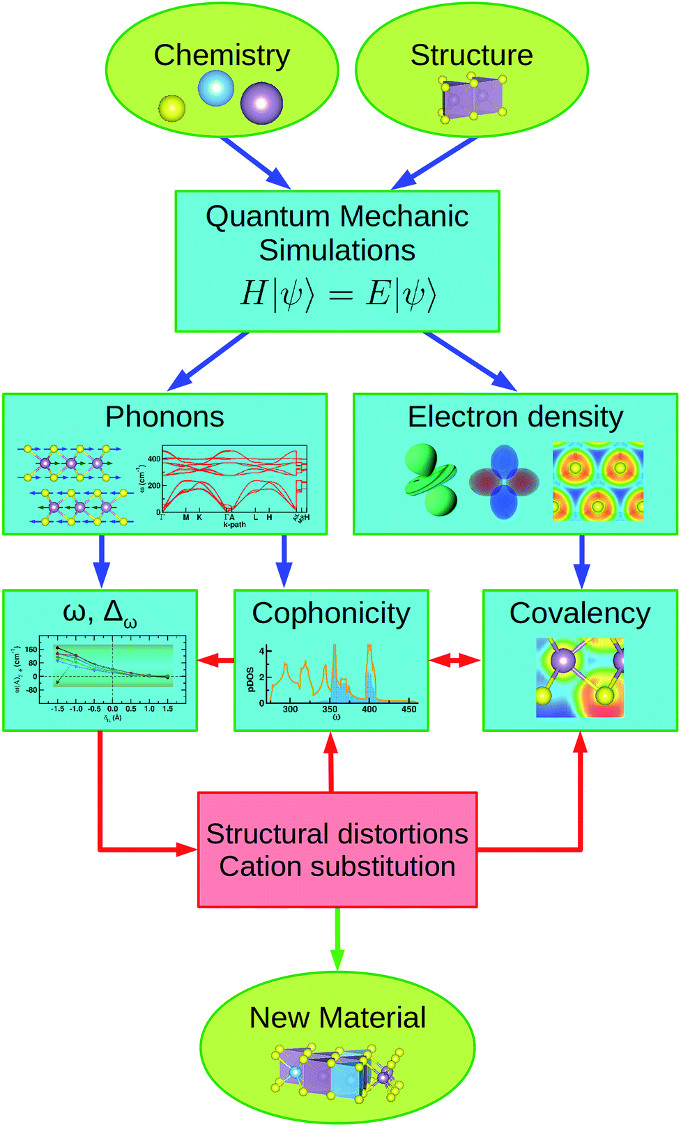 | ||
| Fig. 8 Schematic diagram showing the investigation protocol applied in this work. Ab initio simulations are employed to calculate the electronic and dynamic properties of the selected system; cophonicity and covalency determine the vibrational frequencies and their variation against variable load. By proper cation substitutions and/or induced structural distortions it is possible to tune the electro-dynamic coupling, producing a new material with enhanced tribologic properties. | ||
We first analyze the distortion patterns to characterize the phonon modes calculated in the IBZ; we then compute the mode Grüneisen parameters to isolate those modes that are mainly affected by a change in the unit cell volume and studied how the associated vibrational frequencies change by changing the interlayer distance.
We individuate the electronic origin of the frequency shift by analyzing the electronic charge distribution about the atomic species at different interlayer distances. We find that compressing the system along an axis orthogonal to parallel layers induce charge flow from the interlayer to the intralayer region. Specifically, we observe that the M cation accommodates the excess of electronic charge via a change in the eg orbital population; this corresponds to charge accumulation along an axis orthogonal to the layer and containing the M cation.
The fragmented information provided by the orbital polarization analysis is recollected by means of the covalency descriptor. The M–X bond becomes more ionic after charge accumulation on the M cation, while it preserves its covalent character at increased interlayer distance. Covalency is thus varying with variable load; on the other hand, we find that the M–X pair cophonicity can be considered constant in a wide load range. We therefore choose the cophonicity, calculated at null load, to characterize the system and its response.
We then parameterize the variability of the structural response by quantifying the variation amplitude of the frequency modes and we relate it to the cophonicity. We find that, irrespective of the mode, small variation amplitude values associated to the sliding modes are realized for WTe and Ti:MoS systems, that are thus expected to be the least affected systems among those here studied.
The variation amplitude can be adjusted by controlling the M–X pair cophonicity; the latter, in turn, can be tuned by selective cation substitution inducing variations of the covalency and the structural distortions, or by external applied fields.
The investigation protocol used in the present work can also be applied to the study of the electron–vibrational coupling effects in electronic materials, as alternative to standard methodologies.42–45
5 Acknowledgements
This work has been done with the support of inter-sectoral mobility and quality enhancement of research teams at Czech Technical University in Prague, CZ.1.07/2.3.00/30.0034. This work was supported by the IT4Innovations Centre of Excellence project (CZ.1.05/1.1.00/02.0070), funded by the European Regional Development Fund and the national budget of the Czech Republic via the Research and Development for Innovations Operational Programme, as well as Czech Ministry of Education, Youth and Sports via the project Large Research, Development and Innovations Infrastructures (LM2011033). The use of vesta46 software is also acknowledged.References
- M. Chhowalla, H. S. Shin, G. Eda, L.-J. Li, K. P. Loh and H. Zhang, Nat. Chem., 2013, 5, 263–275 CrossRef PubMed.
- Q. H. Wang, K. Kalantar-Zadeh, A. Kis, J. N. Coleman and M. S. Strano, Nat. Nanotechnol., 2012, 7, 699–712 CrossRef CAS PubMed.
- Z. Yin, H. Li, H. Li, L. Jiang, Y. Shi, Y. Sun, G. Lu, Q. Zhang, X. Chen and H. Zhang, ACS Nano, 2012, 6, 74–80 CrossRef CAS PubMed.
- K. F. Mak, C. Lee, J. Hone, J. Shan and T. F. Heinz, Phys. Rev. Lett., 2010, 105, 136805 CrossRef PubMed.
- S. Cahangirov, C. Ataca, M. Topsakal, H. Sahin and S. Ciraci, Phys. Rev. Lett., 2012, 108, 126103 CrossRef CAS PubMed.
- T. Onodera, Y. Morita, A. Suzuki, M. Koyama, H. Tsuboi, N. Hatakeyama, A. Endou, H. Takaba, M. Kubo, F. Dassenoy, C. Minfray, L. Joly-Pottuz, J.-M. Martin and A. Miyamoto, J. Phys. Chem. B, 2009, 113, 16526–16536 CrossRef CAS PubMed.
- T. Onodera, Y. Morita, R. Nagumo, R. Miura, A. Suzuki, H. Tsuboi, N. Hatakeyama, A. Endou, H. Takaba, F. Dassenoy, C. Minfray, L. Joly-Pottuz, M. Kubo, J.-M. Martin and A. Miyamoto, J. Phys. Chem. B, 2010, 114, 15832 CrossRef CAS PubMed.
- T. Liang, W. G. Sawyer, S. S. Perry, S. B. Sinnott and S. R. Phillpot, Phys. Rev. B: Condens. Matter Mater. Phys., 2008, 77, 104105 CrossRef.
- Y. Morita, T. Onodera, A. Suzuki, R. Sahnoun, M. Koyama, H. Tsuboi, N. Hatakeyama, A. Endou, H. Takaba, M. Kubo, C. A. D. Carpio, T. Shin-yoshi, N. Nishino, A. Suzuki and A. Miyamoto, Appl. Surf. Sci., 2008, 254, 7618–7621 CrossRef CAS.
- G. Levita, A. Cavaleiro, E. Molinari, T. Polcar and M. C. Righi, J. Phys. Chem. C, 2014, 118, 13809–13816 CAS.
- A. Cammarata and T. Polcar, Inorg. Chem., 2015, 54, 5739–5744 CrossRef CAS PubMed.
- M. R. Laskar, D. N. Nath, L. Ma, E. W. Lee, C. H. Lee, T. Kent, Z. Yang, R. Mishra, M. A. Roldan, J.-C. Idrobo, S. T. Pantelides, S. J. Pennycook, R. C. Myers, Y. Wu and S. Rajan, Appl. Phys. Lett., 2014, 104, 092104 CrossRef.
- D. J. Lewis, A. A. Tedstone, X. L. Zhong, E. A. Lewis, A. Rooney, N. Savjani, J. R. Brent, S. J. Haigh, M. G. Burke, C. A. Muryn, J. M. Raftery, C. Warrens, K. West, S. Gaemers and P. OâĂŹBrien, Chem. Mater., 2015, 27, 1367–1374 CrossRef CAS.
- K. Zhang, S. Feng, J. Wang, A. Azcatl, N. Lu, R. Addou, N. Wang, C. Zhou, J. Lerach, V. Bojan, M. J. Kim, L.-Q. Chen, R. M. Wallace, M. Terrones, J. Zhu and J. A. Robinson, Nano Lett., 2015, 15(10), 6586–6591 CrossRef CAS PubMed.
- (a) D. Teer, Wear, 2001, 251, 1068–1074 CrossRef; (b) N. Renevier, V. Fox, D. Teer and J. Hampshire, Surf. Coat. Technol., 2000, 127, 24–37 CrossRef CAS; (c) N. Renevier, J. Hamphire, V. Fox, J. Witts, T. Allen and D. Teer, Surf. Coat. Technol., 2001, 142âĂŞ144, 67–77 CrossRef.
- C. Rice, R. J. Young, R. Zan, U. Bangert, D. Wolverson, T. Georgiou, R. Jalil and K. S. Novoselov, Phys. Rev. B: Condens. Matter Mater. Phys., 2013, 87, 081307 CrossRef.
- X. Zhang, X.-F. Qiao, W. Shi, J.-B. Wu, D.-S. Jiang and P.-H. Tan, Chem. Soc. Rev., 2015, 44, 2757–2785 RSC.
- H. Sahin, S. Tongay, S. Horzum, W. Fan, J. Zhou, J. Li, J. Wu and F. M. Peeters, Phys. Rev. B: Condens. Matter Mater. Phys., 2013, 87, 165409 CrossRef.
- J. P. Oviedo, S. KC, N. Lu, J. Wang, K. Cho, R. M. Wallace and M. J. Kim, ACS Nano, 2015, 9, 1543–1551 CrossRef CAS PubMed.
- J. P. Perdew, K. Burke and M. Ernzerhof, Phys. Rev. Lett., 1996, 77, 3865–3868 CrossRef CAS PubMed.
- (a) G. Kresse and J. FurthmÃijller, Comput. Mater. Sci., 1996, 6, 15–50 CrossRef CAS; (b) G. Kresse and D. Joubert, Phys. Rev. B: Condens. Matter Mater. Phys., 1999, 59, 1758–1775 CrossRef CAS.
- A. K. Geim and I. V. Grigorieva, Nature, 2013, 499, 419–425 CrossRef CAS.
- S. Grimme, J. Comput. Chem., 2006, 27, 1787–1799 CrossRef CAS PubMed.
- B. Schönfeld, J. J. Huang and S. C. Moss, Acta Crystallogr., Sect. B: Struct. Sci., 1983, 39, 404–407 CrossRef.
- V. Kalikhman, Inorg. Mater., 1983, 19, 957–962 Search PubMed.
- L. Brixner, J. Inorg. Nucl. Chem., 1962, 24, 257–263 CrossRef CAS.
- W. Schutte, J. D. Boer and F. Jellinek, J. Solid State Chem., 1987, 70, 207–209 CrossRef CAS.
- V. L. Kalikhman, Neorg. Mater., 1983, 19, 1060–1065 CAS.
- A. A. Yanaki and V. A. Obolonchik, Inorg. Mater., 1973, 9, 1855–1858 Search PubMed.
- A. Togo, F. Oba and I. Tanaka, Phys. Rev. B: Condens. Matter Mater. Phys., 2008, 78, 134106 CrossRef.
- W. Setyawan and S. Curtarolo, Comput. Mater. Sci., 2010, 49, 299–312 CrossRef.
- R. Aksoy, Y. Ma, E. Selvi, M. C. Chyu, A. Ertas and A. White, J. Phys. Chem. Solids, 2006, 67, 1914–1917 CrossRef CAS.
- Z.-H. Chi, X.-M. Zhao, H. Zhang, A. F. Goncharov, S. S. Lobanov, T. Kagayama, M. Sakata and X.-J. Chen, Phys. Rev. Lett., 2014, 113, 036802 CrossRef PubMed.
- T. Livneh and E. Sterer, Phys. Rev. B: Condens. Matter Mater. Phys., 2010, 81, 195209 CrossRef.
- A. P. Nayak, Z. Yuan, B. Cao, J. Liu, J. Wu, S. T. Moran, T. Li, D. Akinwande, C. Jin and J.-F. Lin, ACS Nano, 2015, 9(9), 9117–9123 CrossRef CAS PubMed.
- Z. Zhao, H. Zhang, H. Yuan, S. Wang, Y. Lin, Q. Zeng, G. Xu, Z. Liu, G. K. Solanki, K. D. Patel, Y. Cui, H. Y. Hwang and W. L. Mao, Nat. Commun., 2015, 6, 7312 CrossRef CAS PubMed.
- (a) R. F. V. Bader, Atoms in Molecules: a Quantum Theory, Oxford University Press, New York, 1990 Search PubMed; (b) W. Tang, E. Sanville and G. Henkelman, J. Phys.: Condens. Matter, 2009, 21, 084204 CrossRef CAS PubMed.
- A. Cammarata and J. M. Rondinelli, Phys. Rev. B: Condens. Matter Mater. Phys., 2013, 87, 155135 CrossRef.
- M. J. Han, C. A. Marianetti and A. J. Millis, Phys. Rev. B: Condens. Matter Mater. Phys., 2010, 82, 134408 CrossRef.
- A. Cammarata and J. M. Rondinelli, J. Chem. Phys., 2014, 141, 114704 CrossRef PubMed.
- A. Cammarata, W. Zhang, P. S. Halasyamani and J. M. Rondinelli, Chem. Mater., 2014, 26, 5773–5781 CrossRef CAS.
- C. Attaccalite, L. Wirtz, M. Lazzeri, F. Mauri and A. Rubio, Nano Lett., 2010, 10, 1172–1176 CrossRef CAS PubMed.
- F. Flicker and J. van Wezel, Nat. Commun., 2015, 6, 7034 CrossRef CAS PubMed.
- N. Zarifi, H. Liu and J. S. Tse, Sci. Rep., 2015, 5, 10458 CrossRef CAS PubMed.
- C. Chen, Z. Xie, Y. Feng, H. Yi, A. Liang, S. He, D. Mou, J. He, Y. Peng, X. Liu, Y. Liu, L. Zhao, G. Liu, X. Dong, J. Zhang, L. Yu, X. Wang, Q. Peng, Z. Wang, S. Zhang, F. Yang, C. Chen, Z. Xu and X. J. Zhou, Sci. Rep., 2013, 2, 2411 Search PubMed.
- K. Momma and F. Izumi, J. Appl. Crystallogr., 2008, 41, 653–658 CrossRef CAS.
Footnote |
| † Electronic supplementary information (ESI) available: Mathematical definition of cophonicity metric. See DOI: 10.1039/c5ra24837j |
| This journal is © The Royal Society of Chemistry 2015 |