Multifunctionalization of carbon nanotube fibers with the aid of graphene wrapping
Fancheng
Meng
ab,
Jingna
Zhao
a,
Yuting
Ye
ab,
Xiaohua
Zhang
*a,
Shan
Li
c,
Jingjing
Jia
c,
Zuoguang
Zhang
c and
Qingwen
Li
*a
aKey laboratory of Nano-Devices and Applications, Suzhou Institute of Nano-Tech and Nano-Bionics, Chinese Academy of Sciences, Ruoshui Road 398, Suzhou 215123, China. E-mail: xhzhang2009@sinano.ac.cn; qwli2007@sinano.ac.cn; Fax: +86 512 6287 2552; Tel: +86 512 6287 2552
bGraduate University of Chinese Academy of Sciences, Yuquan Road 19, Beijing 100049, China
cSchool of Materials Science and Engineering, Beihang University, Xueyuan Road 37, Beijing 100191, China
First published on 22nd June 2012
Abstract
Carbon nanotube (CNT) fibers are promising candidates for developing multifunctional textiles. The direct introduction of functional guests within or around CNT fibers meets problems due to the rough fiber surface and weak interfacial bindings. To improve the functionality and performance stability, we report a new method to modify the surface roughness and level of functionalization of CNT fibers, by wrapping graphene oxide (GO) or reduced graphene (RG) around them. Besides the functional groups on the graphene sheets, the introduction of a graphene layer also has smoothing and shield effects, resulting in higher tensile strength and improved and stabilized performance. The electrochemical and photocurrent applications were exploited by depositing polyaniline around GO-wrapped CNT fibers and TiO2 around RG-wrapped fibers, with a capacitance up to 229.5 F cm−3 and a photocurrent density of 132 μA cm−2, respectively. The present technique has the advantage that the mechanical and functional properties can be optimized by simply modifying the core CNT fiber via polymer infiltration during the fiber spinning.
1 Introduction
Because of their excellent mechanical and electrical properties and ability to be integrated with conventional textile technologies, carbon nanotube (CNT) fibers have demonstrated promising applications in various fields, such as sensors, supercapacitors, and artificial muscles.1 In order to improve the multifunctionality of CNT fibers, scientists have tried the introduction of guest particles such as TiO2, SiO2, LiFePO4, Si3N4, MgB2, and organic functional molecules within and mainly around the fibers.2–4 (Similarly, metal nanoparticles have also been deposited on the surface of individual CNTs or CNT assemblies for achieving multifunctional applications.5–8) The assembly structure of CNTs enables the functionality of guest particles to be maintained and also allows weavability, knottability, and durability even at a high guest fraction up to 95 wt%.3 However, the functional layers might significantly damage the mechanical properties of the CNT fiber due to the chemical modification of the CNTs, and the fabrication and performance depend strongly on the morphology of the fiber surface, which depends on the twist angle, densification level, and the type of the original CNTs.9,10 Thus, it becomes necessary to modify the fiber surface in advance of the multifunctionalization.In this paper, we present a non-covalent treatment by wrapping graphene nanosheets (GNSs) around CNT fibers to modify the fiber surfaces. The core fiber provides the mechanical support and electron-conducting path, where the GNS layer acts as an efficient interface modulator and a template for the deposition of functional nanoparticles. GNSs can be used because they possess high surface area, chemical activity, flexibility, and close contact with the CNTs.11–16 This choice was also recently reported, where functional textiles were produced by coating textile support structures with both GNSs and functional nanoparticles.17 In this work it is found that the introduction of GNSs can maintain the mechanical and electrical properties of the supporting CNT fibers and has the advantage of tuning the functionality just by using GNSs with different levels of oxidation. Two example studies are provided where graphene oxide (GO) and reduced GO (RG) were used, respectively. After the deposition of polyaniline (PANI) on the GO-wrapped CNT fiber, a high volumetric capacitance of 229 F cm−3 was achieved, and the responsive photocurrent density was up to 132 μA cm−2 when TiO2 was coated on the RG-wrapped fiber. These values are much more stable and higher than those for non-wrapped fibers.
2 Experimental section
The CNT fibers were continuously drawn from spinnable vertically aligned CNT arrays,9,18 which were produced by a sustained chemical vapour deposition (CVD) growth.19 During the spinning, a drop of ethanol, 1 wt% poly(vinyl alcohol) (PVA)/dimethyl sulfoxide solution, 1 wt% chitosan/water solution, or 1 wt% poly(diallydimethylammonium chloride) (PDDA)/water solution was used to densify the fiber or to introduce polymers to interlink the CNTs.10 The as-produced fiber was immersed for 2 h in a 0.05 g L−1 GO or RG/water solution, which also contained 1–2 vol% of dimethylformamide (DMF), as schematically shown in Fig. 1. After being washed with deionized water, the fiber was immersed again in the same solution for an additional 2 h and then dried at 60 °C in order to get the optimized GNS wrapping. In our study, GO was prepared from natural graphite powder (300 mesh, Alfa Aesar) by the modified Hummers method20,21 and dispersed in water, and RG was prepared by using Li's method.22 The GNSs were a few tens of μm in length and ∼1 nm in thickness.23 | ||
| Fig. 1 Schematic illustration of GNS wrapping. A CNT fiber is immersed into the GNS solution. GNSs accumulate around the fiber in the solution and cling to the fiber during the drawing-out. | ||
PANI was deposited onto the fibers by in situ anodic electro-polymerization in a conventional three-electrode system. The deposition was carried out at a constant potential of 0.75 V, against a saturated calomel electrode. This potential cannot be higher because thereafter PANI might change from emeraldine to pernigraniline.24 CNT fibers and Pt foil were used as the working and counter electrodes, respectively. The solution used here contained 0.05 M aniline and 1 M H2SO4. After the deposition, usually within 5–10 min, PANI-coated fibers were washed with deionized water and dried at 60 °C.
The TiO2 deposition was performed at 400 °C using the metal-organic CVD technique,25 where titanium tetraisopropoxide (>98%, Adamas Reagent Co. Ltd.) was used as the precursor. The precursor was initially vaporized at 200 °C and then carried into the deposition zone by 400 sccm argon. The deposition time was fixed at 10 min.
3 Results and discussion
The as-spun fibers were >800 MPa in tensile strength and 8–10 μm in diameter. Our method to modify the fibers is to dip them into a graphene solution for GO or RG wrapping (Fig. 1). Due to π–π stacking, GNSs prefer to accumulate around the CNT fiber and tightly cling to the fiber surface due to surface tension during the drawing-out. After being immersed in the solution and then dried, the fibers, namely GO/RG@CNT, can be transferred to incorporate guest nanoparticles for developing the multifunctionality.3.1 Graphene wrapping
Fig. 2a and b show scanning electron microscopy (SEM) images of the GO@CNT. Firstly, the wrapping has a smoothing effect on the core fiber. Although GO itself contains abundant oxygenated groups26 and is not exactly planar, its large lateral area ensures bridging over a large number of CNTs on the fiber surface. As a result, the rough surface becomes much smoother as shown in Fig. 2a. It was found that even after being dipped into the GO/water solution several times, uncovered areas still existed. This should be attributed to the hydrophobic nature of CNTs, as tiny air bubbles can be formed on the fiber surface. In order to obtain a full and uniform wrapping, we added drops of DMF into the solution, about 1–2 vol%, to decrease the solution's surface tension. The results are shown in Fig. 2c and d, where the wrapping was significantly improved. Therefore, DMF-assisted wrapping was always used in this study, including for the RG wrapping process. | ||
| Fig. 2 SEM images showing the wrapping of GO without (a and b) and with (c and d) DMF assistance, see the text. (e) Stress–strain curves for the CNT and GO@CNT fibers. The scale bars are 1 μm in (a and c) and 5 μm in (b and d). | ||
Secondly, the wrapping has a shielding effect, that is, the mechanical and electrical properties of the core fiber can be well maintained after the wrapping. Fig. 2e shows the results of a tensile test on CNT fibers with and without the GO wrapping. The original fiber was 848 MPa in strength, and after the wrapping the strength was improved by 42 MPa. This is not surprising because the bridging of the GO layer allows additional load transfer between non-neighboring CNTs on the fiber surface. However, as GNSs are less electrically conducting than CNTs due to their abundant functional groups, after GNS wrapping the electrical conductivity had decreased from 425 to 375–415 S cm−1, depending on the level of oxidation.
The third and most important advantage of the wrapping is the functionalization effect, because after the wrapping the chemically inert CNT fiber might contain plenty of oxygen-containing groups and thus become chemically active. Importantly, the level of surface functionalization can be easily tuned by wrapping with GNSs with different levels of oxidation/reduction. Therefore, due to their different numbers and types of functional groups, GO and RG can be two typical wrapping materials to develop multifunctional fibers. In the following parts of this study, we present in detail two different functionalization treatments based on GNS wrapping, including comparisons with non-wrapped fibers as well. The two examples are PANI and TiO2 depositions around different fibers. The PANI deposition was performed by anodic electro-polymerization, and the TiO2 nanoparticles were coated using the CVD method. The obtained samples were denoted as PANI/TiO2@GO/RG@CNT.
3.2 GO-wrapped CNT fibers for electrochemical applications
Fig. 3a–c show the SEM images of different PANI-deposited fibers. Without GNS wrapping, PANI nanowires (30–100 nm in diameter and hundreds of nm in length) accumulated around the CNTs and connected with each other (Fig. 3a). Therefore, the nanowires were aligned following the twisting angle. The deposition was different after the wrapping, see Fig. 3b and c. As the wrapping smoothed the fiber surface, PANI patterns no longer followed the tube alignment, as indicated by the flattened entanglement of PANI nanofibrils. On the GO@CNT surface, fibril entanglement was dominant, probably due to the widely existing highly polar oxygen-containing groups26 which provide more nucleation sites for aniline monomers to anchor and polymerize simultaneously. The PANI@GO@CNT fiber possesses the highest volumetric capacitance (Cv), see Fig. 3d. For example, after depositing PANI for 5 min Cv = 206 F cm−3, and after an additional 5 min the value increased to 229 F cm−3, both higher than the corresponding values for PANI@CNT. (The capacitance was calculated from cyclic voltammograms obtained at 0.02 V s−1 in 1 M H2SO4 solution.) However, for the PANI@RG@CNT, Cv was only 155 F cm−3 (5 min) or 186 F cm−3 (10 min). GO shows better results as an electrode material because the abundant oxygenated groups provide additional pseudo-capacitances.27 When being negatively charged, GO also becomes more hydrophilic and this facilitates the deposition of PANI because those groups serve as nucleation sites.28 | ||
| Fig. 3 SEM images of fiber morphologies for pure CNT (a, inset), PANI@CNT (a), PANI@RG@CNT (b), and PANI@GO@CNT (c), respectively. (d) Volumetric capacitance of PANI-deposited fibers as a function of deposition time. The tensile strengths of the PANI@GO@CNT fibers are plotted with the dashed line. (e) Galvanostatic charge–discharge curves measured at a current of 2 μA and operating voltage of 0.8 V, where PANI was deposited for 5 min. The scale bars are 1 μm except for the inset (10 μm). | ||
Furthermore, the oxygenated areas on GO might induce structural deformation of PANI molecules during the deposition. The Raman spectra in Fig. 4 reveal that the adsorption peak for C–H in-plane bending in the aromatic rings of PANI was at 1133 cm−129,30 when the pure CNT fiber was used. When PANI was deposited on GO surfaces, the absorption peak shifted to 1171 cm−1 due to the deformed structure. These two peaks were both found for the PANI@RG@CNT fibers as there are still a certain number of un-reduced groups and structural defects.
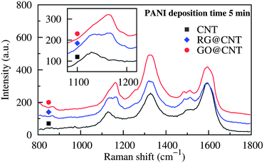 | ||
| Fig. 4 Raman spectra for PANI-deposited fibers. The absorption peak at 1133 cm−1 shifted to 1171 cm−1 as the number of oxygenated groups increased. | ||
Fig. 3e shows the galvanostatic charge–discharge curves obtained at a current of I = 2 μA and an operating voltage of V = 0.8 V. The discharge times t were 33, 27, and 38 s, for PANI-deposited CNT, RG@CNT, and GO@CNT fibers, respectively. Therefore, the volumetric energy density  and averaged power density Pv = Ev/t can be calculated. After 5 min deposition on the GO@CNT, Ev = 1.83 × 10⁻² W h cm−3 and Pv = 1.73 W cm−3. Notice that the capacitance per unit length for this sample was 0.16 mF cm−1, which, when taking account of the fiber diameter of ∼10 μm, is seven times higher than that for ZnO@Kevlar fiber hybrid fibers (0.02 mF cm−1).31
As mentioned above, the smoothed fiber surface might ensure the improved stability of performance. This was indeed observed in the experiments. Without GNS wrapping, the Cv for the PANI@CNT fibers ranged from 152 to 205 F cm−3, for deposition time of 5 min. (Notice that only the average of 183 F cm−3 is shown in Fig. 3d.) The large variation arises from the different roughnesses of the fiber surfaces, a result of the spinning process, densification level, and array quality. However, the variation of Cv for the PANI@GO@CNT fibers was found to be within only 20–25 F cm−3. For mechanical properties, the shielding effect of GNS wrapping can also benefit the PANI-based fibers. As PANI is weak when loaded with external stresses, after deposition for 10 min all the fiber strengths became ∼150 MPa smaller. However, the PANI@GO@CNT fibers were still 738 MPa in strength (Fig. 3d), 48 and 96 MPa stronger than the PANI@CNT and PANI@RG@CNT fibers, respectively.
3.3 RG-wrapped CNT fibers for photocurrent applications
In contrast to the electrochemical performance based on PANI deposition, where GO shows better performance, RG can be used to wrap CNT fibers to realize improved photocurrent conversion by coating with TiO2 nanoparticles. Fig. 5 shows the Raman spectra and photocurrent responses for TiO2-deposited fibers. (The response measurement was carried out in the three-electrode system with a light intensity near the fiber surface of 100 mW cm−2.) Without GNS wrapping the photocurrent density of the TiO2@CNT fibers was only about 25 μA cm−2. When GNS was wrapped before depositing TiO2, the photoconversion efficiency was improved by a factor of 2 (∼50 μA cm−2) and 5 (∼132 μA cm−2) for GO and RG, respectively. This is a reasonable result as the Raman intensity shown in Fig. 5a demonstrated that more TiO2 nanoparticles were deposited around the RG@CNT fibers (the peaks at 144, 397, 518, and 619 cm−1 correspond to the anatase phase of TiO2).25,32 Therefore the incident light can be captured and converted more efficiently. The more planar and conductive nature of RG is also important for the tight binding with TiO2 nanoparticles, providing larger and more effective donor–acceptor interfaces to transport the photogenerated charges.33 | ||
| Fig. 5 a) Raman spectra for TiO2-coated fibers. The marked intensity peaks within 750 cm−1are demonstration of CNT and anatase TiO2. (b) Photocurrent response versus time profile for TiO2-coated fibers, where the light intensity near the fiber surfaces was set to 100 mW cm−2. | ||
Fig. 6 shows the fracture morphology for TiO2@CNT and TiO2@RG@CNT fibers. The TiO2 nanoparticles formed a thick (∼200 nm) layer on the latter fibers, whereas they were distributed separately on the former fibers, in agreement with the Raman scattering results. For a good fiber-based device, the functional parts like the TiO2 layer should be well bound on the fiber surfaces. Due to the strong binding of ∼1.5 eV per TiO2 entity between the TiO2 and the carbon sp2 layer,34 these nanoparticles were found to stay on the fiber even at the fracture (Fig. 6a). However, for the TiO2@RG@CNT fibers, the TiO2 layer might be exfoliated due to the relatively weak RG–CNT bonding, which, for example, was calculated to be 151–260 meV between a benzene molecule and a single-walled CNT.35 From Fig. 6b one can find that such exfoliation was only found at the fracture where the slippage of the CNTs caused the RG wrapping to be unstable and thus TiO2 and RG dropped off together. For the other sites along the fiber, the core fiber was still well covered by the TiO2 layer.
 | ||
| Fig. 6 SEM images of the fracture morphology for TiO2@CNT (a) and TiO2@RG@CNT (b) fibers. The scale bars are 10 μm. | ||
3.4 Modifying the level of graphene wrapping
Considering the smoothing and shielding effects of GNS wrapping, it is possible to modify the core CNT fiber to improve the mechanical properties without sacrificing the functional performance. For example, polymer infiltration can be used during the fiber spinning.10 In fact, it is also an efficient way to tune the wrapping level, as the functional groups of the polymers might form tight bindings with the GNSs. Three different polymers were used, namely PVA, chitosan, and PDDA. The infiltrated long-chain molecules like PVA and chitosan can interact with non-neighboring CNTs (bridging effect) and thus improve the load transfer within the fiber.36–38 The tensile strengths for the PVA- and chitosan-infiltrated fibers were 1025 and 1062 MPa, respectively (Table 1). However, the advantage of bridging is cancelled out by the electrostatic repulsion between the cationic groups of PDDA, which leads to the expansion of the CNT spacing.39 As a result, the PDDA-infiltrated fiber was only 768 MPa in strength. After wrapping GO around these fibers, the tensile strength was improved by 42–70 MPa, indicating that the smoothing and shielding were well maintained, and were of the highest level for the PDDA infiltration due to the electrostatic interaction between GO and PDDA.| Polymer | Strength (MPa) | Conductivity (S cm−1) |
|---|---|---|
| Ethanol | 848 → 890 | 425 → 375 |
| PVA | 1025 → 1080 | 485 → 443 |
| Chitosan | 1062 → 1110 | 493 → 447 |
| PDDA | 768 → 838 | 391 → 341 |
However, for the electrical conductivity, two different changes were observed, see Table 1. For PVA and chitosan, the bridging effect draws non-neighboring tubes closer and thus benefits the electron hopping between tubes, while the expansion of the CNT spacing due to PDDA decreases the conductivity. After GO was wrapped around the fibers, there was usually a ∼10% loss in conductivity. Fortunately, the magnitude of conductivity, ranging from 341 to 447 S cm−1, is enough for an efficient fiber-shaped electrode. By taking the example of PVA, the PANI@GO@CNT-PVA composite fiber had a capacitance Cv = 240 F cm−3, over 10 F cm−3 larger than that without the PVA modification.
4 Conclusions
In summary, we have combined mechanically strong CNT fibers with functional GNSs by a simple assembly process. Uniform and full GNS wrapping maintains the fibers’ mechanical and electrical properties, and provides the fibers with designed functionality. For example, by integrating foreign nanoparticles of PANI and TiO2, multifunctional fibers with enhanced energy storage capability and photocurrent conversion can be produced, respectively. These fibers are also lightweight and flexible, and therefore can be readily integrated with textile technology. As GNSs can be widely used for multifunctional applications, the wrapping process can be further extended for other applications such as sensors and actuators.References
- W. Lu, M. Zu, J.-H. Byun, B.-S. Kim and T.-W. Chou, Adv. Mater., 2012, 24, 1805–1833 CrossRef CAS.
- J. Foroughi, G. M. Spinks, G. G. Wallace, J. Oh, M. E. Kozlov, S. Fang, T. Mirfakhrai, J. D. W. Madden, M. K. Shin, S. J. Kim and R. H. Baughman, Science, 2011, 334, 494–497 CrossRef CAS.
- M. D. Lima, S. Fang, X. Lepró, C. Lewis, R. Ovalle-Robles, J. Carretero-González, E. Castillo-Martínez, M. E. Kozlov, J. Oh, N. Rawat, C. S. Haines, M. H. Haque, V. Aare, S. Stoughton, A. A. Zakhidov and R. H. Baughman, Science, 2011, 331, 51–55 CrossRef CAS.
- T. Chen, S. Wang, Z. Yang, Q. Feng, X. Sun, L. Li, Z.-S. Wang and H. Peng, Angew. Chem., Int. Ed., 2011, 50, 1815–1819 CrossRef CAS.
- G. Ren and Y. Xing, Nanotechnology, 2006, 17, 5596–5601 CrossRef CAS.
- L. K. Randeniya, A. Bendavid, P. J. Martin and C.-D. Tran, Small, 2010, 6, 1806–1811 CrossRef CAS.
- G. Xu, J. Zhao, S. Li, X. Zhang, Z. Yong and Q. Li, Nanoscale, 2011, 3, 4215–4219 RSC.
- H. Im, E. Y. Jang, A. Choi, W. J. Kim, T. J. Kang, Y. W. Park and Y. H. Kim, ACS Appl. Mater. Interfaces, 2012, 4, 2338–2342 CAS.
- J. Zhao, X. Zhang, J. Di, G. Xu, X. Yang, X. Liu, Z. Yong, M. Chen and Q. Li, Small, 2010, 6, 2612–2617 CrossRef CAS.
- J. Jia, J. Zhao, G. Xu, J. Di, Z. Yong, Y. Tao, C. Fang, Z. Zhang, X. Zhang, L. Zheng and Q. Li, Carbon, 2011, 49, 1333–1339 CrossRef CAS.
- Y. Zhu, S. Murali, W. Cai, X. Li, J. W. Suk, J. R. Potts and R. S. Ruoff, Adv. Mater., 2010, 22, 3906–3924 CrossRef CAS.
- N. Patra, Y. Song and P. Král, ACS Nano, 2011, 5, 1798–1804 CrossRef CAS.
- L. Peng, Y. Feng, P. Lv, D. Lei, Y. Shen, Y. Li and W. Feng, J. Phys. Chem. C, 2012, 116, 4970–4978 CAS.
- S. Das, R. Seelaboyina, V. Verma, I. Lahiri, J. Y. Hwang, R. Banerjee and W. Choi, J. Mater. Chem., 2011, 21, 7289–7295 RSC.
- X. Lu, H. Dou, B. Gao, C. Yuan, S. Yang, L. Hao, L. Shen and X. Zhang, Electrochim. Acta, 2011, 56, 5115–5121 CrossRef CAS.
- S. H. Lee, D. H. Lee, W. J. Lee and S. O. Kim, Adv. Funct. Mater., 2011, 21, 1338–1354 CrossRef CAS.
- G. Yu, L. Hu, M. Vosgueritchian, H. Wang, X. Xie, J. R. McDonough, X. Cui, Y. Cui and Z. Bao, Nano Lett., 2011, 11, 2905–2911 CrossRef CAS.
- M. Zhang, K. R. Atkinson and R. H. Baughman, Science, 2004, 306, 1358–1361 CrossRef CAS.
- Q. Li, X. Zhang, R. F. DePaula, L. Zheng, Y. Zhao, L. Stan, T. G. Holesinger, P. N. Arendt, D. E. Peterson and Y. T. Zhu, Adv. Mater., 2006, 18, 3160–3163 CrossRef CAS.
- W. S. Hummers and R. E. Offeman, J. Am. Chem. Soc., 1958, 80, 1339–1339 CrossRef CAS.
- N. I. Kovtyukhova, P. J. Ollivier, B. R. Martin, T. E. Mallouk, S. A. Chizhik, E. V. Buzaneva and A. D. Gorchinskiy, Chem. Mater., 1999, 11, 771–778 CrossRef CAS.
- D. Li, M. B. Müller, S. Gilje, R. B. Kaner and G. G. Wallace, Nat. Nanotechnol., 2008, 3, 101–105 CrossRef CAS.
- X. Geng, L. Niu, Z. Xing, R. Song, G. Liu, M. Sun, G. Cheng, H. Zhong, Z. Liu, Z. Zhang, L. Sun, H. Xu, L. Lu and L. Liu, Adv. Mater., 2010, 22, 638–642 CrossRef CAS.
- K. Aoki and S. Tano, Electrochim. Acta, 2005, 50, 1491–1496 CrossRef CAS.
- S. Orlanducci, V. Sessa, M. L. Terranova, G. A. Battiston, S. Battiston and R. Gerbasi, Carbon, 2006, 13, 2839–2843 CrossRef.
- W. Gao, L. B. Alemany, L. Ci and P. M. Ajayan, Nat. Chem., 2009, 1, 403–408 CrossRef CAS.
- B. Xu, S. Yue, Z. Sui, X. Zhang, S. Hou, G. Cao and Y. Yang, Energy Environ. Sci., 2011, 4, 2826–2830 CAS.
- J. Xu, K. Wang, S.-Z. Zu, B.-H. Han and Z. Wei, ACS Nano, 2010, 4, 5019–5026 CrossRef CAS.
- M. C. Bernard and A. Hugot-Le Goff, Electrochim. Acta, 2006, 52, 595–603 CrossRef CAS.
- H. Wang, Q. Hao, X. Yang, L. Lu and X. Wang, ACS Appl. Mater. Interfaces, 2010, 2, 821–828 CAS.
- J. Bae, M. K. Song, Y. J. Park, J. M. Kim, M. Liu and Z. L. Wang, Angew. Chem., Int. Ed., 2011, 50, 1683–1687 CrossRef CAS.
- M. P. Moret, R. Zallen, D. P. Vijay and S. B. Desu, Thin Solid Films, 2000, 366, 8–10 CrossRef CAS.
- Y. H. Ng, I. V. Lightcap, K. Goodwin, M. Matsumura and P. V. Kamat, J. Phys. Chem. Lett., 2010, 1, 2222–2227 CrossRef CAS.
- M. I. Rojas and E. P. M. Leiva, Phys. Rev. B: Condens. Matter Mater. Phys., 2007, 76, 155415 CrossRef.
- L. M. Woods, S. C. Bǎdescu and T. L. Reinecke, Phys. Rev. B: Condens. Matter Mater. Phys., 2007, 75, 155415 CrossRef.
- C. Fang, J. Zhao, J. Jia, Z. Zhang, X. Zhang and Q. Li, Appl. Phys. Lett., 2010, 97, 181906 CrossRef.
- K. Liu, Y. Sun, X. Lin, R. Zhou, J. Wang, S. Fan and K. Jiang, ACS Nano, 2010, 4, 5827–5834 CrossRef CAS.
- W. Liu, X. Zhang, G. Xu, P. D. Bradford, X. Wang, H. Zhao, Y. Zhang, Q. Jia, F.-G. Yuan, Q. Li, Y. Qiu and Y. Zhu, Carbon, 2011, 49, 4786–4791 CrossRef CAS.
- S. Wang, S. P. Jiang and X. Wang, Nanotechnology, 2008, 19, 265601 CrossRef.
| This journal is © The Royal Society of Chemistry 2012 |