Electrocatalytic reforming of waste plastics into high value-added chemicals and hydrogen fuel†
Rui
Shi‡
a,
Ke-Sheng
Liu‡
ab,
Fulai
Liu
a,
Xiao
Yang
a,
Chun-Chao
Hou
a and
Yong
Chen
 *ab
*ab
aKey Laboratory of Photochemical Conversion and Optoelectronic Materials & HKU-CAS Joint Laboratory on New Materials, Technical Institute of Physics and Chemistry, Chinese Academy of Sciences, Beijing 100190, People's Republic of China. E-mail: chenyong@mail.ipc.ac.cn
bUniversity of Chinese Academy of Sciences, Beijing 100049, People's Republic of China
First published on 19th October 2021
Abstract
The upcycling of waste plastic offers an attractive way to protect the environment and turn waste into value-added chemicals and H2 fuel. Herein, we report a novel electroreforming strategy to upcycle waste polyethylene terephthalate into high value-added chemicals, such as terephthalate and carbonate, over a Pd modified Ni foam catalyst. This system exhibits excellent electrocatalytic activity (400 mA cm−2 at 0.7 V vs. RHE) and high selectivity (95%)/faradaic efficiency (93%) for the product carbonate. Our work demonstrates a technology that can not only transform waste polyethylene terephthalate into value-added chemicals but also generate H2 fuel via an all-in-one electro-driven process.
Over the past century, polymeric plastics have become ubiquitous in our daily life. As of the end of 2020, more than 8.3 billion tons of polymeric plastics had been manufactured since the 1950s.1,2 As a representative, polyethylene terephthalate (PET) accounts for 13% of the total plastic output and is widely used in the manufacture of videos, food packaging and particularly beverage bottles,3,4 which is one of the most widely used and yet discarded materials. According to relevant statistics, the output of PET grows at a compound rate of 4.5% each year.5 Unfortunately, the majority of this plastic accumulates in landfills or is left in the environment, leading to serious plastic pollution and loss of valuable resources. Thus, the implementation of widespread recycling of plastic waste can not only transform waste into valuable chemicals, but also achieve measurable cost-avoidance for its treatment.6
Currently, 20% of PET bottles are recycled mainly via the mechanical method.7 This method results in structural deterioration and the recycled products do not possess the same properties as the original PET.8 As a result, these mechanically-recycled inferior products finally end up in landfills.9 Chemical recycling approaches including hydrolysis,10 methanolysis,11 and glycolysis12 are promising to achieve recovery at the molecular level.13 Generally, these approaches adopt the degradation of PET to its starting monomers, such as terephthalic acid, ethylene glycol (EG) or bis(hydroxyethyl) terephthalate, and then subsequent polymerization to reproduce the “same” PET. However, the current processes for chemical recycling of PET have intractable obstacles including high energy input, low efficiency and complexity, which greatly restrict their further practical application.14 Recently, electrocatalytic synthesis has become a powerful method to produce a variety of chemicals while simultaneously generating H2 fuel from water under certain conditions.15–17 Unlike existing chemical production technologies used in industrial processes, electrosynthesis can be conducted at ambient temperature and pressure, uses electricity as the only energy input, and produces fuel-cell-grade H2. Although electrosynthesis of simple molecules has been researched extensively, plastics have been overlooked as substrates to achieve both chemical conversion and H2 generation in one system.18 Therefore, it is of significance to develop more efficient electrocatalytic systems for not only transforming end-of-use polymers into valuable products, but also generating high-demand H2 for further agricultural, pharmaceutical and renewable energy applications.
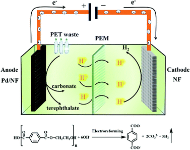
Herein, we report a Pd modified Ni foam (Pd/NF) catalyst that can achieve effective electroreforming of PET into high value-added chemicals, exhibiting a current density of 400 mA cm−2 at 0.7 V vs. RHE. After 20 h of electrolysis at 0.7 V vs. RHE, the conversion of PET can reach up to 100%. The value-added chemical products of electroreforming of PET are terephthalate and carbonate. The selectivity and faradaic efficiency of carbonate are 95% and 93%, respectively, while the yield of terephthalate is 99%. Finally, we prepared a home-made two-electrode electrolysis cell by using the Pd/NF electrocatalyst as the anode and Ni foam as the cathode with a real-world PET bottle as the substrate. Our catalytic system could not only produce high value-added chemicals (terephthalate/carbonate) at the anode, but also generate H2 fuel via the reduction reaction (Scheme 1). This proof-of-concept demonstration of the electroreforming of waste plastics offers a sustainable and scalable route toward simultaneous plastic waste elimination, chemical synthesis and generation of renewable fuels.
 | ||
| Scheme 1 Schematic illustration of the electroreforming of PET into high value-added chemicals and H2 fuel. | ||
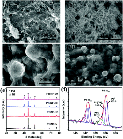
Pd/NF was synthesized through a simple displacement reaction of Ni foam in H2PdCl4 aqueous solution without any additives, and the corresponding experimental details are demonstrated in the ESI.† Pd/NF catalysts synthesized in 5 mM, 10 mM, 20 mM, and 30 mM H2PdCl4 solutions are denoted as Pd/NF-5, Pd/NF-10, Pd/NF-20, and Pd/NF-30, respectively. The morphologies of the as-prepared Pd/NF were examined using a scanning electron microscope (SEM). As shown in Fig. 1a–d, the morphologies of Pd loaded on Ni foam gradually change from network structures to particles from Pd/NF-5 to Pd/NF-30. The TEM images demonstrate that the network structures and particles are composed of agglomerates of nanosheets and nanoparticles of 10–20 nm size, respectively (Fig. S1 in the ESI†). The XRD patterns of Pd/NF (Fig. 1e) exhibit three characteristic diffraction peaks located at 40.1°, 46.7° and 68.1°, which are assigned to the (111), (200) and (220) crystal facets of Pd (JCPDS, 46-1043), respectively. The other three diffraction peaks located at 44.5°, 51.8° and 76.4° are attributed to Ni foam. To identify the chemical valence states of Pd, the curve-fitted XPS core level spectrum of Pd 3d of Pd/NF-10 is presented in Fig. 1f. The Pd 3d spectrum is fitted with three symmetric peaks around 335.6 eV (attributed to Pd0), 336.3 eV (attributed to Pd(OH)x), and 337.4 eV (attributed to PdO),19,20 indicating that the surface of the Pd/NF catalyst is partially oxidized during the preparation process.
 | ||
| Fig. 1 SEM images of (a) Pd/NF-5, (b) Pd/NF-10, (c) Pd/NF-20, and (d) Pd/NF-30; (e) XRD patterns of Pd/NF; and (f) Pd 3d XPS spectrum of Pd/NF-10. | ||
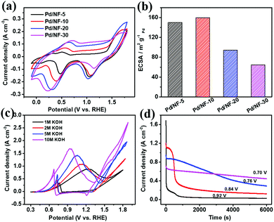
In the process of PET electroreforming, PET will be hydrolyzed to terephthalate and ethylene glycol (EG). Based on this, we firstly investigated the oxidation activity of EG catalyzed by Pd/NF, which determines the final electroreforming performance of PET. The cyclic voltammetry (CV) curves of Pd/NF in 1 M KOH are shown in Fig. 2a. The first oxidation wave of Pd/NF ranges from 0.38 to 0.85 V vs. RHE, which is attributed to the oxidation of Pd. The reduction wave ranging from 0.02 to 0.65 V vs. RHE corresponds to the reduction of Pd surface oxides.21 The electrochemically active surface area (ECSA) of Pd/NF is estimated via the reduction of Pd oxides based on a previous calculation method,20 and the calculation results are shown in Table S1 in the ESI.† As shown in Fig. 2b, Pd/NF-10 possesses the largest ECSA, indicating that the network structure of Pd/NF-10 can expose more catalytically active sites to drive the electrocatalytic reactions. Hence, Pd/NF-10 is used as the optimized catalyst to perform the following electrochemical measurements.
Then, CV curves were recorded in KOH with different concentrations to investigate the catalytic ability of Pd/NF-10 toward the EG oxidation. As shown in Fig. 2c, in 1.0 M KOH, there are two oxidation peaks at 1.24 and 0.76 V vs. RHE in the forward and backward sweeps, which are ascribed to EG oxidation and removal of CO-like intermediate species, respectively.22–24 A maximum current density (∼880 mA cm−2) for the EG oxidation is observed in 1.0 M KOH. It is also found that the maximum current density increases gradually with increasing concentration of the KOH electrolyte from 1 M to 10 M, and the corresponding oxidation peaks shift toward more negative potentials from 1.24 to 0.92 V vs. RHE. Therefore, a strong alkaline environment is beneficial for the EG oxidation, so the following data are collected in 10 M KOH. It should be pointed out that the oxygen evolution reaction (OER) does not occur in the potential range of EG oxidation (Fig. S2 in the ESI†). Also, the hydrogen evolution reaction (HER) performance remains unchanged in the presence of different concentrations of EG (Fig. S3 in the ESI†).
The optimal potential of Pd/NF-10 for EG oxidation is evaluated with the chronoamperometry method. As shown in Fig. 2d, the current density drops sharply at the peak potential (0.92 V vs. RHE), indicating the formation of carbonaceous intermediate species, such as CO-type species, which poison the Pd/NF catalyst.25 However, a lower electrolysis potential would dramatically improve the stability of the Pd/NF-10 catalyst. When the electrolysis is carried out at 0.7 V vs. RHE, the current density can be stably maintained and the slight decrease is attributed to the consumption of EG. Previous work revealed that fewer CO-type species were generated at lower oxidation potentials.26 In order to balance the current density and stability, 0.7 V vs. RHE is chosen as the optimal potential for EG oxidation.
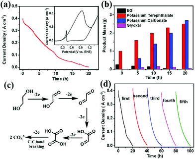
Before electroreforming, 2 g PET was firstly pretreated in 60 mL of 10 M KOH solution at 60 °C for 4 h. During this pre-treatment process, PET releases monomers (terephthalate and EG) with 40% yield in an alkaline solution (Fig. S4 in the ESI†), which can promote the catalytic process of PET electroreforming. The CV curve of PET electroreforming demonstrates that the current density is approximately 400 mA cm−2 at 0.7 V vs. RHE (Fig. 3a). Subsequently, the chronoamperometry curve for PET electroreforming is performed at 0.7 V vs. RHE. It can be seen that the current density drops close to zero after 20 h, implying that the oxidation reaction of EG has been completed. 1H-NMR and 13C-NMR spectroscopy techniques are used to monitor the electroreforming products, and it can be found that the mass of EG gradually decreases with the gradual increase of carbonate. Meanwhile, glyoxal is also produced during this process (Fig. 3b and Fig. S5–S8 in the ESI†). Based on this, a C–C bond breaking mechanism for the alkaline EG oxidation is proposed herein for a better understanding of this process (Fig. 3c).27,28 After 20 h of the electroreforming process, the conversion of PET reached almost 100%, and its conversion products are terephthalate and carbonate (Fig. 3b). Terephthalate can be easily separated from the reaction system due to its poor solubility in 10 M KOH electrolyte, and its yield reaches up to 99%. For the product carbonate, its selectivity and faradaic efficiency are 95% and 93%, respectively. The stability of Pd/NF-10 is then analyzed through the electroreforming test at 0.7 V vs. RHE. As shown in Fig. 3d, 97% of the initial current density is retained after 4 cycles, indicating the high stability of Pd/NF-10 for PET electroreforming. Meanwhile, it also exhibits stably high selectivity and faradaic efficiency of products (Fig. S9 in the ESI†). The recovered Pd/NF-10 catalyst maintains its structure and morphology without damage after 5 cycles of electroreforming (Fig. S10–S12 in the ESI†).
To go a further step toward the real-world practical use, we applied Pd/NF-10 as the anode and Ni foam as the cathode to electroreform the real-world PET bottle in a two-electrode system. The CV curve exhibits a current density of 100 mA cm−2 at a cell voltage of 1.01 V (Fig. S13a in the ESI†). The electrocatalytic performance is much better than that of recently reported overall water-splitting systems (10 mA cm−2 at cell voltages ranging from 1.4 to 1.7 V).29,30 After 25 h of electrolysis, the current density is close to zero, indicating that the catalytic reaction is complete (Fig. S13b in the ESI†). The selectivity and faradaic efficiency of carbonate are calculated to be 95% and 91%, respectively, while the yield of terephthalate is 96% (Fig. S14 in the ESI†). For the hydrogen evolution reaction in the cathode, the faradaic efficiency of H2 fuel is 98% (Fig. S15 in the ESI†). Furthermore, our PET electroreforming strategy has considerable potential economic benefits based on a preliminary techno-economic analysis (Fig. S16 in the ESI†).31–33
In summary, we demonstrate a novel electrocatalytic reforming approach to successfully achieve the upcycling of PET into high value-added chemicals (terephthalate and carbonate) by using the Pd/NF electrocatalyst. This system exhibits excellent catalytic activity (400 mA cm−2 at 0.7 V vs. RHE), high selectivity (95%) and high faradaic efficiency (93%) for carbonate. This proof-of-concept demonstration offers a sustainable and facile route toward simultaneous plastic waste elimination, chemical synthesis and generation of renewable fuels. It is expected that this study will stimulate relevant studies for the recycling of waste plastics.
We thank the Strategic Priority Research Program of the Chinese Academy of Sciences (XDB17000000) and the National Natural Science Foundation of China (21773275, 21971250) for the financial support. Y. C. acknowledges the CAS-Croucher Funding Scheme for Joint Laboratories.
Conflicts of interest
The authors declare no conflicts of interest.Notes and references
- R. Geyer, J. R. Jambeck and K. L. Law, Sci. Adv., 2017, 3, e1700782 CrossRef PubMed.
- X. C. Jiao, K. Zheng, Q. X. Chen, X. D. Li, Y. M. Li, W. W. Shao, J. Q. Xu, J. F. Zhu, Y. Pan, Y. Sun and Y. Xie, Angew. Int., Ed. Chem., 2020, 59, 15497–15501 CrossRef CAS PubMed.
- W. T. S. Huck, Nature, 2011, 472, 425–426 CrossRef CAS PubMed.
- S. M. Al-Salem, P. Lettieri and J. Baeyens, Waste Manage, 2009, 29, 2625–2643 CrossRef CAS PubMed.
- L. Bartolome, M. Imran, B. G. Cho, W. A. Al-Masry and D. H. Kim, in Recent Developments in the Chemical Recycling of PET. In Material Recycling-Trends and Perspectives, ed. D. Achilias, InTech, Rijeka, Croatia, 2012, ch. 2, pp. 65–78 Search PubMed.
- C. Jehanno, I. Flores, A. P. Dove, A. J. Muller, F. Ruiperez and H. Sardon, Green Chem., 2018, 20, 1205–1212 RSC.
- A. Rahimi and J. M. Garcia, Nat. Rev. Chem., 2017, 1, 0046 CrossRef.
- S. M. Biros, B. M. Bridgewater, A. Villeges-Estrada, J. M. Tanski and G. Parkin, Inorg. Chem., 2002, 41, 4051–4057 CrossRef CAS PubMed.
- M. Avadanei, M. Drobota, I. Stoica, E. Rusu and V. Barboiu, J. Polym. Sci. Part A: Polym. Chem., 2010, 48, 5456–5467 CrossRef CAS.
- T. Yoshioka, T. Sato and A. Okuwaki, J. Appl. Polym. Sci., 1994, 52, 1353–1355 CrossRef CAS.
- H. Kurokawa, M. Ohshima, K. Sugiyama and H. Miura, Polym. Degrad. Stab., 2003, 79, 529–533 CrossRef CAS.
- L. Wang, G. A. Nelson, J. Toland and J. D. Holbrey, ACS Sustainable Chem. Eng., 2020, 8, 13362–13368 CrossRef CAS.
- H. Chen, K. Wan, Y. Y. Zhang and Y. Q. Wang, ChemSusChem, 2021, 14, 4123–4136 CrossRef CAS PubMed.
- D. Paszun and T. Spychaj, Ind. Eng. Chem. Res., 1997, 36, 1373–1383 CrossRef CAS.
- Y. Xu and B. Zhang, Chem. Soc. Rev., 2014, 43, 2439–2450 RSC.
- N. N. Meng, C. B. Liu, Y. Liu, Y. F. Yu and B. Zhang, Angew. Chem., Int. Ed., 2019, 58, 18908–18912 CrossRef CAS PubMed.
- C. Q. Huang, Y. Huang, C. B. Liu, Y. F. Yu and B. Zhang, Angew. Chem., Int. Ed., 2019, 58, 12014–12017 CrossRef CAS PubMed.
- H. Zhou, Y. Ren, Z. H. Li, M. Xu, Y. Wang, R. X. Ge, X. G. Kong, L. R. Zheng and H. H. Duan, Nat. Commun., 2021, 12, 4679 CrossRef CAS PubMed.
- W. W. Su, R. Sun, F. F. Ren, Y. F. Yao, Z. H. Fei, H. W. Wang, Z. T. Liu, R. Xing and Y. K. Du, Appl. Surf. Sci., 2019, 491, 735–741 CrossRef CAS.
- D. Chai, W. Wang, W. K. Dong, Y. M. Kang, Y. J. Dong and Z. Q. Lei, Appl. Catal., A, 2016, 525, 1–8 CrossRef CAS.
- S. S. Chen, Z. Z. Yang, A. J. Wang, K. M. Fang and J. J. Feng, J. Colloid Interface Sci., 2018, 509, 10–17 CrossRef CAS PubMed.
- H. Xu, P. P. Song, C. Fernandez, J. Wang, M. S. Zhu, Y. Shiraishi and Y. K. Du, ACS Appl. Mater. Interfaces, 2018, 10, 12659–12665 CrossRef CAS PubMed.
- F. F. Ren, L. J. Xu, H. Xu, Y. W. Tang, Z. T. Liu and Y. K. Du, J. Alloys Compd., 2021, 854, 157075 CrossRef CAS.
- R. L. Zhang, J. J. Duan, Z. Han, J. J. Feng, H. Huang, Q. L. Zhang and A. J. Wang, Appl. Surf. Sci., 2020, 506, 144791 CrossRef CAS.
- Y. Song, C. Wei, X. Zhang, X. Wei, X. Song and Z. Sun, Mater. Chem. Phys., 2015, 161, 153–161 CrossRef CAS.
- L. Q. Wang, H. Meng, P. K. Shen, C. Bianchini, F. Vizza and Z. D. Wei, Phys. Chem. Chem. Phys., 2011, 13, 2667–2673 RSC.
- A. Mukherjee, W. N. Su, C. J. Pan and S. Basu, J. Electroanal. Chem., 2021, 882, 115006 CrossRef CAS.
- H. Wang, B. Jiang, T. T. Zhao, K. Jiang, Y. Y. Yang, J. W. Zhang, Z. X. Xie and W. B. Cai, ACS Catal., 2017, 7, 2033–2041 CrossRef CAS.
- H. Zhang, Q. Jiang, J. Hadden, F. Xie and D. Riley, Adv. Funct. Mater., 2021, 31, 2008989 CrossRef CAS.
- B. Chen, D. Kim, Z. Zhang, M. Lee and K. Yong, Chem. Eng. J., 2021, 422, 130533 CrossRef CAS.
- Y. W. Lum, J. E. Huang, Z. Y. Wang, M. C. Luo, D. H. Nam, W. R. Leow, B. Chen, J. Wicks, Y. Li, Y. H. Wang, C. T. Dinh, J. Li, T. T. Zhuang, F. W. Li, T. K. Sham, D. Sinton and E. H. Sargent, Nat. Catal., 2020, 3, 14–22 CrossRef CAS.
- P. De Luna, C. Hahn, D. Higgins, S. A. Jaffer, T. F. Jaramillo and E. H. Sargent, Science, 2019, 364, eaav3506 CrossRef CAS PubMed.
- W. R. Leow, Y. Lum, A. Ozden, Y. H. Wang, D. H. Nam, B. Chen, J. Wicks, T. T. Zhuang, F. W. Li, D. Sinton and E. H. Sargent, Science, 2020, 368, 1228–1233 CrossRef CAS PubMed.
Footnotes |
| † Electronic supplementary information (ESI) available: Supplemental experiment section. See DOI: 10.1039/d1cc05032j |
| ‡ These two authors contributed equally. |
| This journal is © The Royal Society of Chemistry 2021 |


