
Dynamic pH measurements of intracellular pathways using nano-plasmonic assemblies†
Kazuki
Bando
a,
Zhiqiang
Zhang
b,
Duncan
Graham
 c,
Karen
Faulds
c,
Katumasa
Fujita
*ade and
Satoshi
Kawata
af
c,
Karen
Faulds
c,
Katumasa
Fujita
*ade and
Satoshi
Kawata
af
aDepartment of Applied Physics, Osaka University, Yamadaoka, Suita, Osaka 565-0871, Japan. E-mail: fujita@ap.eng.osaka-u.ac.jp
bCAS Key Lab of Bio-Medical Diagnostics, Suzhou Institute of Biomedical Engineering and Technology, Chinese Academy of Sciences, 215163, Suzhou, China
cCentre for Molecular Nanometrology, Department of Pure and Applied Chemistry, WestCHEM, University of Strathclyde, Technology and Innovation Centre, 99 George Street, Glasgow, UK
dAdvanced Photonics and Biosensing Open Innovation Laboratory, AIST-Osaka University, Yamadaoka, Suita, Osaka 565-0871, Japan
eTransdimensional Life Imaging Division, Institute for Open and Transdisciplinary Research Initiatives, Osaka University, Yamadaoka, Suita, Osaka 565-0871, Japan
fSerendip Research, Yamadaoka, Suita, Osaka 565-0871, Japan
First published on 25th June 2020
Abstract
Plasmonic Ag nano-assemblies moving in a living cell were employed to visualize the spatiotemporal change of intracellular pH by surface-enhanced Raman scattering. Ag nano-assemblies were functionalized with 4-mercaptobenzoic acid (p-MBA) to monitor the variation of the surrounding pH. SERS spectra from the functionalized nano-assemblies that were transported in a cell were recorded to estimate the local pH on the pathways travelled by the nano-assemblies. 3D nanoparticle tracking and SERS measurements were simultaneously performed to trace the pH dynamics with a spatial accuracy of several tens of nanometers and a temporal resolution of 200 ms, which are sufficient to reveal pH changes associated with intracellular transportation. The pH trajectory of the functionalized nanoparticle can be used to visualize the dynamic change of the chemical environment caused by organelle interactions, such as endosomal trafficking and lysosomal fusion. This breakthrough creates a new paradigm for intracellular analysis using SERS and reveals new capability for rapid use of SERS in biological analysis.
Introduction
Nano-sized metallic nanoparticles provide an enhanced electro-magnetic field on the metal surface when irradiated by light. This field enhancement effect has been utilized to harness the optical effects of the particle and adjacent materials and, in particular, light scattering effects. Surface-enhanced Raman scattering (SERS) is very attractive for scientists to conduct high-sensitivity molecular analysis based on vibrational spectroscopy.1–3 In order to utilize the SERS phenomena for analyzing and imaging molecules, a combination of SERS spectroscopy and microscopy has been performed by using metallic nanostructures to observe a sample with nanometer-scale resolution.4–7To expand SERS techniques to nanoimaging from inside a cell, the use of metallic nanoparticles has been proposed in order to provide the distribution of the intracellular materials. Dynamics and distribution of intracellular molecules such as DNA bases, amino acids and proteins have been observed in time and space.8–11 In addition, to detect intracellular molecules, the functionalization of nanoparticles has been proposed to sense intracellular chemical environments, such as pH. Kneipp et al. reported a temporal change in pH distribution by using silver nanoparticles coated with para mercaptobenzoic acid (p-MBA)12 that showed a pH sensitive response in the spectral data. The measurement of pH dysregulation due to pH stress from the extracellular environment was reported by A. Jaworska et al.13 Although there are several reports using fluorophores for pH sensing,14,15 SERS based pH sensing avoids photobleaching and autofluorescence from cellular proteins. Monitoring changes in pH allows us to know the parameters of various states of cellular activities such as cell division,16 cell metabolism of tumors17 and biosynthesis of cytoplasmic constituent and transportation.18,19 Studies of intracellular pH monitoring or mapping have so far been implemented by illuminating with confocal laser scanning or uniform illumination.20 The pH measurements in cells reveal whole trends of the cellular state or responses due to the environment.21,22 However, pH differs between each organelle. The proton gradient is regulated temporally and spatially to maintain the correct environment for normal function and activity. The cellular cytoplasm is segmented into organelles by lipid membranes and the proton ion gradient is strictly controlled by ion channels or transporters.17 Therefore, precise temporal and spatial pH measurements are necessary in order to understand the local cellular dynamics at the single organelle level.
In this paper, we observed the pH dynamics of intracellular transportation in three-dimensions by using Ag nanoparticles functionalized with p-MBA. In our previous report, we introduced metallic nanoparticles into living cells by endocytosis and traced the motion of the particles by recording SERS spectra.6,11 We applied this dynamic SERS imaging technique to observe the change in pH around the nanoparticles during the endosomal activities surrounding the nanoparticle under intracellular transportation. This three-dimensional pH tracking technique has potential to understand local phenomena at the single cell organelle level such as the intracellular transportation mechanism.
Results and discussion
Self-assembled nanostructure and functionalization for pH sensing
A self-assembled nanostructure having several nano-gaps was designed for local pH sensing with high sensitivity as illustrated in Fig. 1A. The nano-gaps create an enhanced electric field and provide strong SERS signals.23 Firstly, we synthesized Ag nanoparticles with a diameter of 50 nm based on the Lee and Meisel's method.24 The nanoparticles were aggregated in a controlled manner by cross-linking using hexamethylenediamine (HMD).25 In addition, polyvinylpyrrolidone (PVP) was added in order to prevent excess aggregation. Bovine serum albumin (BSA) was added and adsorbed onto the conjugate to further stabilize the nanoparticles and quench any aggregation. We controlled the aggregation conditions for the majority of the particles in order to form aggregates, which was confirmed by SEM (ESI Fig. S1†). The majority of the aggregates were dimers (28% of the all nanoparticles), which can increase the signal enhancement26 by keeping the uptake efficiency relatively high.27 Although the morphology of the particle that occupies the largest number was still monomeric after the aggregation process, more than 50% were counted as aggregates (dimers, trimers and larger aggregates). They provide a highly enhanced Raman signal even at an early stage of endocytosis before the nanoparticles would be accumulated in the late endosome or lysosome.4 Then, p-MBA molecules were conjugated onto the nanoparticle assemblies. p-MBA molecules are known to make a self-assembled monolayer on metallic surfaces through the thiol group binding to the metal.28,29 The sizes of p-MBA molecules are smaller than those of other adsorbed molecules or proteins, therefore, p-MBA can enter into the gap to bind to the surface of the nanoparticles and provide highly effective SERS.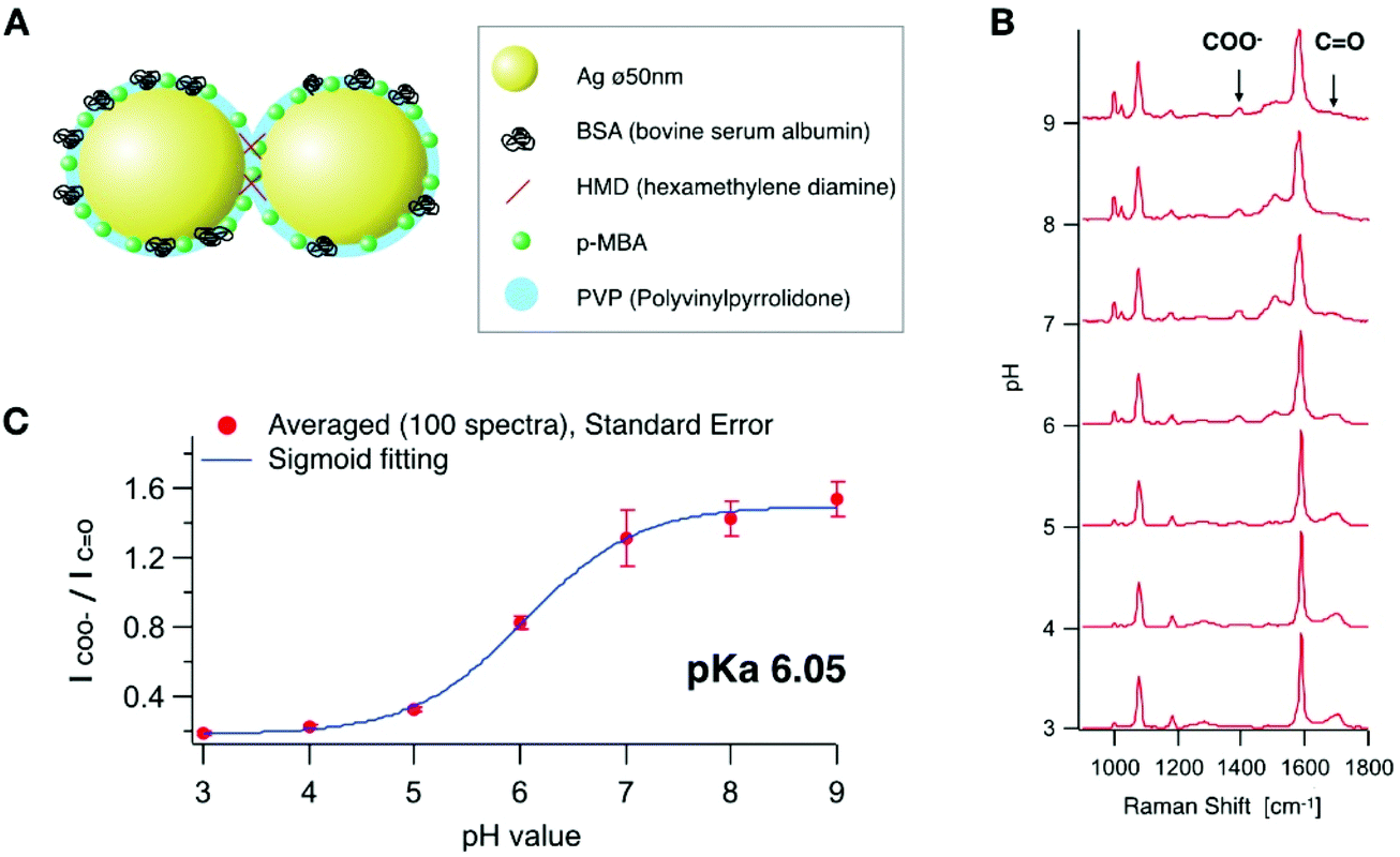 | ||
Fig. 1 (A) Schematic illustration of the functionalized Ag nano-assembly (B) SERS spectra of p-MBA on the aggregated Ag nanoparticles with HMD conjugation at various pH values from 3.0 to 9.0. Each spectrum is an averaged spectrum (n = 100). (C) pH calibration curve obtained by plotting the intensity ratio at 1390 cm−1 (COO−) against 1690 cm−1 (C![[double bond, length as m-dash]](https://www.rsc.org/images/entities/char_e001.gif) O). The error bars represent the standard deviation of over 100 different spectra in one-time SERS line scanning imaging. The calibration curve was fitted with a sigmoidal function. The detail experimental condition is written in the Materials and methods part. The excitation wavelength is 532 nm with a power of 0.3 mW μm−2 and the exposure time was 50 ms. O). The error bars represent the standard deviation of over 100 different spectra in one-time SERS line scanning imaging. The calibration curve was fitted with a sigmoidal function. The detail experimental condition is written in the Materials and methods part. The excitation wavelength is 532 nm with a power of 0.3 mW μm−2 and the exposure time was 50 ms. | ||
We recorded SERS spectra from the synthesized p-MBA conjugated Ag nano-assemblies in solutions at different pH values. The SERS spectra shown in Fig. 1B were recorded from the assembled nanoparticles immobilized on a glass substrate. The surface of the glass substrate was positively charged by being coated with 3-aminopropyl-triethoxysilane to adsorb the Ag nano-assemblies with a negative charge. The glass substrate was filled with McIlvaine solution and adjusted to a different pH for each measurement. SERS imaging was performed by using a home-built line-illumination Raman microscope.30,31 The excitation wavelength was 532 nm and the assembled nanoparticles were imaged with a water-immersion 1.27 NA objective lens (60×, Nikon). The pH was altered between 3.0 and 9.0 on the same substrate, and SERS imaging was performed on the same area (ESI Fig. S2†). 100 SERS measurements were taken at randomly selected spots and the average spectra recorded for each pH condition. Each average SERS spectrum was normalized to the peak intensity at 1590 cm−1 which is assigned to the vibration mode of the aromatic ring.25 As reported in previous literature,32,33 the peak intensity of the carboxylate group (1390 cm−1) and CO stretching mode (1690 cm−1) showed a pH dependent response (Fig. 1(B)). A calibration curve for the pH measurement was obtained by fitting the spectral data with a sigmoidal function (Fig. 1(C)). We confirmed that SERS of the pH probe was sensitive within the range of pH from 3.0 to 9.0 (pKa 6.05), which covers the typical range of intracellular pH (pH 4.8–8).33
Fig. 2A shows the reproducibility of the SERS response of the Ag nano-assemblies at pH 4.0 to 8.5. SERS spectra were recorded from the immobilized Ag nano-assemblies on a glass substrate for pH calculation (Fig. 2B). The Ag nano-assemblies were immersed in two different pH conditions alternately and the result confirmed that the Ag nano-assemblies can be used to measure a temporal change of pH. The reproducibility of the spectrum from each SERS spot during a measurement is necessary to estimate a pH in a cell accurately. The SERS spectrum can be affected by the change in the plasmon resonance of nano-assemblies.34 In our experiment, the error bars in Fig. 1C include variations in pH estimation due to the spectrum change. The other factor we should note is the thermal damage of nano-assemblies by laser irradiation, which also alters the condition for plasmon resonance. In our experiment, Fig. 2B, which showed the spectrum reproducibility over time under the different pH conditions, indicates that the laser irradiation did not cause significant laser damage on the nano-assemblies during the measurement. Although we did not see a significant spectral difference, setting the appropriate parameter such as size distribution of the nano-assemblies and the excitation laser power would be necessary to maintain reproducibility on the spectral shape.
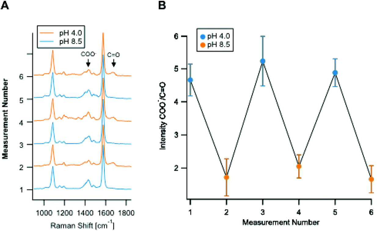 | ||
| Fig. 2 Repetitive measurements of SERS spectra of p-MBA on aggregated Ag nanoparticles at pH 4.0 and pH 8.5 on the same particles. (A) SERS spectra were recorded for 50 spectra and normalized at 1590 cm−1 assigned to ring breathing mode. (B) The intensity ratio of the molecular vibrational mode; COO−/CO (1390 cm−1/1690 cm−1). The error bar is the standard deviation (n = 50). The excitation wavelength is 532 nm with a power of 0.3 mW μm−2 and the exposure time was 50 ms. | ||
Time-lapse SERS imaging with line illumination
To observe the pH dynamics in a living cell, we performed time lapse SERS imaging using the same Raman system.30,31 Fluorescence imaging was also simultaneously performed on the same system. We used HeLa cells as a sample. The cells were incubated with the Ag nano-assemblies and culture medium for 6 hours, which was enough for them to be endocytosed and transported inside a cell prior to the measurement.35 In order to understand the location of Ag nano-assemblies in the cells, we used Lyso Tracker Blue (L7527, Thermo Fisher Scientific) to indicate the intracellular lysosomes by fluorescence imaging.Fig. 3A shows the result of time-lapse SERS and fluorescence imaging of a live HeLa cell. SERS and fluorescence images were obtained every 5.5 s. The SERS images show the distribution of the intensity of the Raman peak at 1590 cm−1, assigned to the aromatic ring vibration mode of p-MBA. Fig. 3B shows the trajectory of an Ag nano-assembly in a cell, which is indicated by the white color, recorded every 5.5 s. The position of the assembly was calculated by 2D Gaussian fitting to the SERS image at 1590 cm−1. The Ag nano-assembly moved straight ahead and then turned back the way it traveled halfway during the measurement. This linear motion of the assembly suggests that the Ag nano-assembly might be being transported by a motor protein such as kinesin or dynein along the intracellular transportation network of microtubules.34
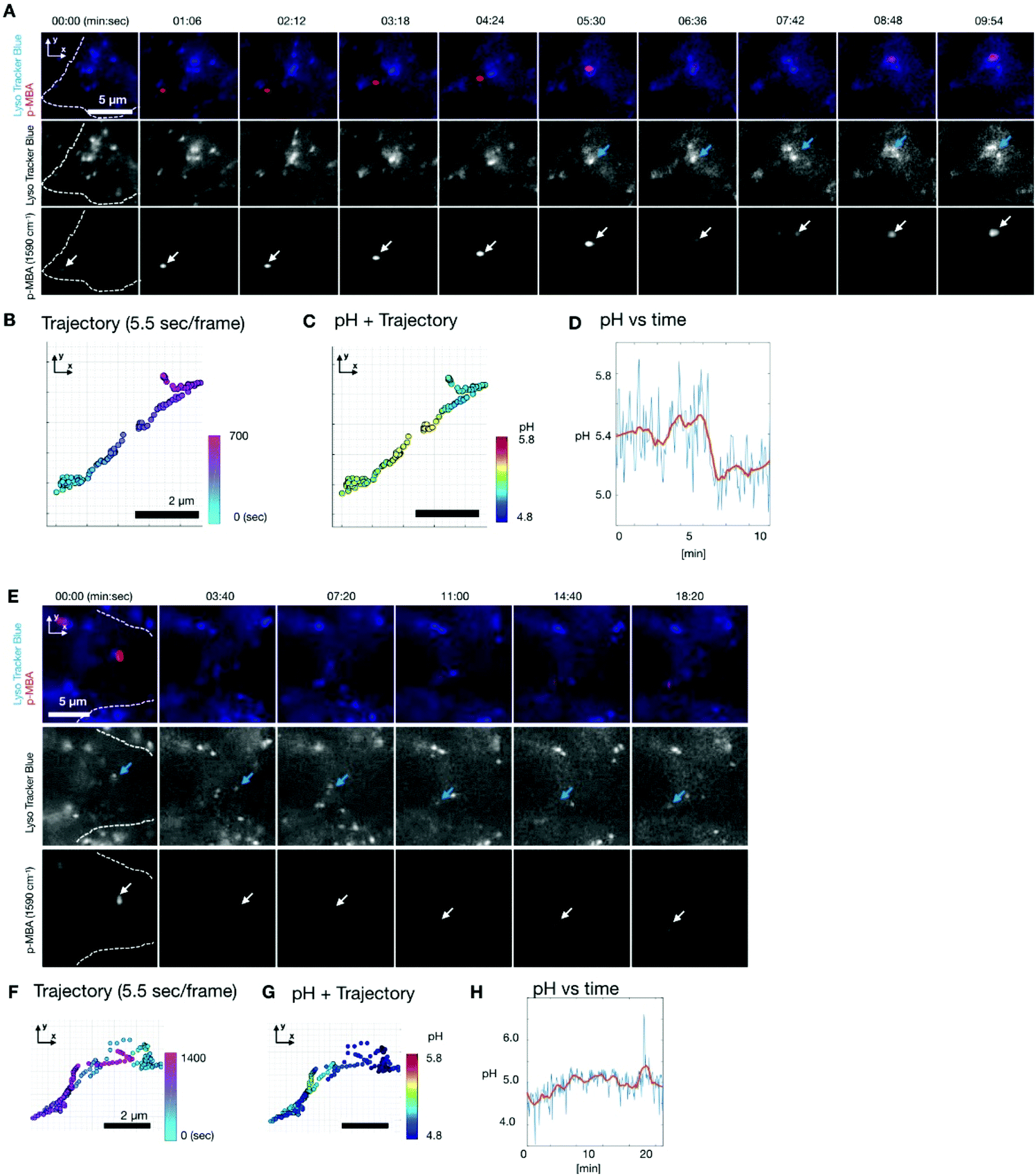 | ||
| Fig. 3 Time-lapse SERS and fluorescence imaging result of a living HeLa cell. (A, E) Merged image of the Lyso Tracker and the SERS intensity map at 1590 cm−1 (top line), the Lyso Tracker (middle line) and the SERS intensity map at 1590 cm−1 (bottom line), respectively. The images were taken every 5.5 s interval and showed every 6 frames for (A) (every 10 frames for (E)). White indicates the p-MBA signal from around a targeted nanoparticle and blue indicates the lysosome for each frame. (B, F) Enlarged trajectory of the p-MBA signal at the white area at the bottom line of (A and E). The color bar indicates time. The axis is the same as that of (A) and (E) respectively. (C, G) Enlarged trajectory of the local pH at the nanoparticle. The color bar indicates pH. The axis is the same as that of (A) and (E) respectively. (D, H) Time-course pH change at the white area at the bottom line of (A). The blue line indicates the raw pH value and the orange line is the smoothed pH (moving average). The laser power was 0.3 mW μm−2 with 532 nm excitation and the exposure time was 50 ms per line. | ||
The pH around the nano-assembly was calculated from the spectra by using the pH calibration curve (Fig. 3D) at each measured frame and plotted on the trajectory as shown in Fig. 3C. The data shows that the pH dynamics of the nano-assembly correlated with time and location in the cell. Initially, the pH was around pH 5.4 for 5 minutes and then the pH decreased suddenly from about 5.4 to 5.1 in 2 minutes. When the sudden pH decrease was observed, it was confirmed that the position of the Ag nano-assembly overlapped with a lysosome, as indicated by the fluorescence image in Fig. 3A. This observation implies that the sudden pH change around the Ag nano-assembly was due to the fusion of an endosome into a lysosome. Lysosomes are known to maintain a highly acidic pH due to its digestive function in a cell.35 Since the Ag nano-assembly was introduced into the cell through endocytosis, the Ag nano-assembly will be enclosed by phospholipid layers.5 It is known that the typical size of the lysosome is of 100–500 nm diameter, and the size increases to 500–1500 nm as a result of membrane fusion.36 The spatial resolution of the slit confocal microscopy is 255 nm for x and y directions using a NA-1.27 objective lens, where the accuracy in localization of nano-assembly by 2D Gaussian fitting is ∼20 nm. Considering the measurement conditions and simultaneous imaging results of SERS and fluorescence, we propose that this shows that the Ag nano-assembly was transported from a late endosome to a lysosome.
Another Ag nano-assembly showed a different behavior in terms of motion and pH (Fig. 3E–H), which was obtained under the same experimental conditions as the data in Fig. 3A–D. The SERS and fluorescence images indicate that the Ag nano-assembly moved with a lysosome. The motion of the Ag nano-assembly was well-confined in a limited volume after about 5 minutes of measurements. After that, the Ag nano-assembly was found to move in a relatively linear motion. The pH value was mostly below 5.0 during the measurements (Fig. 3G–H). This result indicates that the Ag nano-assembly was already enclosed in a lysosome at the beginning of the measurement.
3D particle tracking and SERS sensing
We applied the Ag nano-assemblies to 3D nanoparticle tracking and simultaneous SERS measurements in a living HeLa cell (see “Materials and methods” for details).6,11 We used a combination of dual-focus dark-field microscopy and Raman spectroscopy. The dual-focus dark-field image detects the x, y, and z position of a targeted nano-assembly and provides feedback to two galvanometer mirrors for lateral scanning and an objective lens mounted for axial scanning to keep irradiating the same nano-assembly moving in 3D space for continuous SERS measurements. Both the dual-focus dark-field images and SERS spectrum were obtained every 200 ms and the number of total image frames was 500 (see ESI Movie SM1†). In this measurement, the functionalized nanoparticles traveled in an area ranging ∼1 μm for x, ∼1.5 μm for y, and 1 μm for the z axis (Fig. 4(A)). The spatial resolution for the x–y direction was 350 nm, which is obtained from the full width half maximum of the Gaussian fitting of the dark-field image of the nanoparticle (Fig. S3†). The accuracy for the x–y direction and the z direction is ± 22 nm and ± 35 nm, respectively.10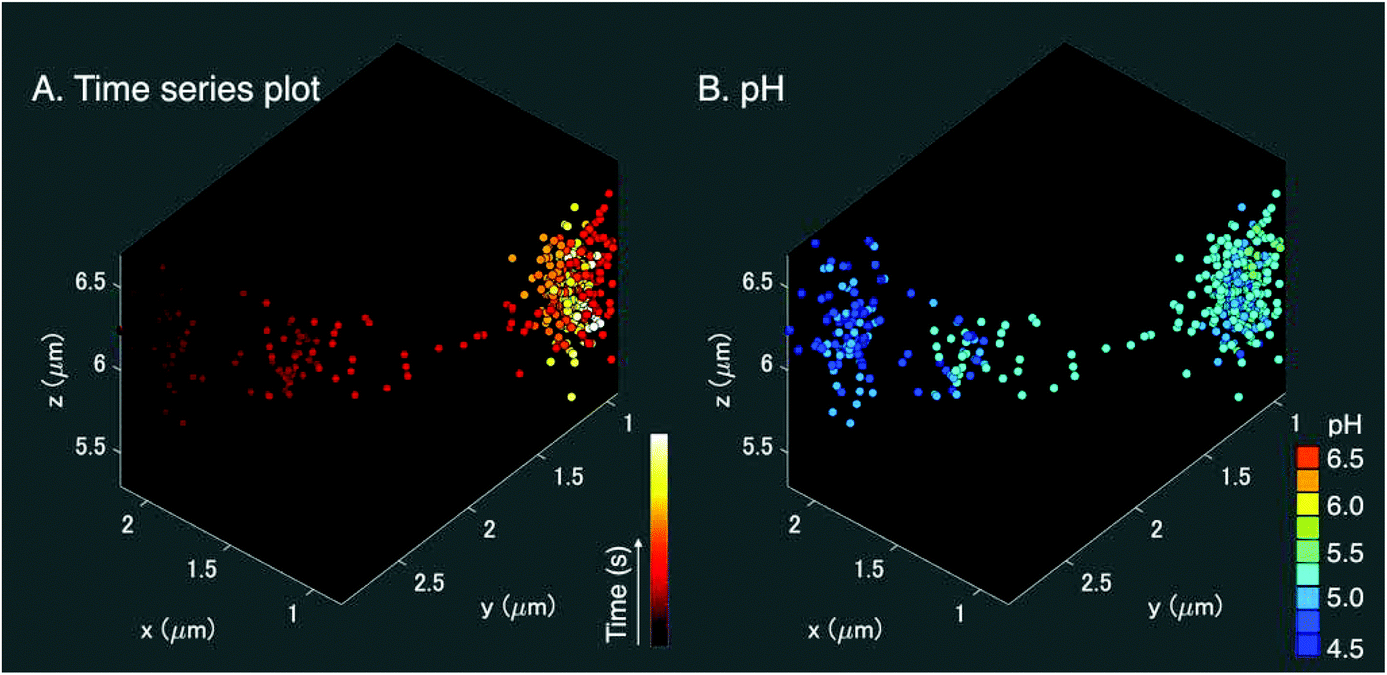 | ||
| Fig. 4 (A) 3D plot of the nanoparticle trajectory during intracellular transportation in a HeLa cell. The plot consists of 500 data points. The position of the nanoparticle was measured every 200 ms. The color scale represents the time course of the trajectory. (B) 3D plot of the nanoparticle trajectory and pH change during the intracellular transportation in a HeLa cell. The color scale shows the pH value obtained by the SERS intensity ratio of COO− to CO. The laser power was 0.3 mW μm−2 with 532 nm excitation and the exposure time was 50 ms per line. | ||
A 3D pH plot corresponding to the trajectory map is shown in Fig. 4(B). The pH value was estimated by using the intensity ratio of the 1390 cm−1 and 1690 cm−1 bands for every single frame and plotted in the 3D space. The pH value was about 4.5 at the start of the measurement and increased to 5.25. This pH range was in agreement with a transition from late endosome to lysosome,18,19 and the change in pH occurred in the opposite manner to the result shown in Fig. 3(A–D). These facts indicate that the pH increase observed in Fig. 4(B) is likely due to alkalization by fusion of the vesicle that enclosed the nano-assemblies and a vesicle with low pH, implying that a lysosome that contained nano-assemblies was fused with an early or a late endosome with a pH higher than the lysosome.19 The main player in endosomal acidification is the vacuolar ATPase, which consists of two multi-subunit domains, the transmembrane V0 and the cytoplasmic V1, and works as a proton pump. It is known that the region of assembly of the two sectors: V1 and V0 of the ATPase in the late endosome increases after the early endosome.37 The lysosome is then more acidic and it suggests that ATPase works more actively. The ATPase system could temporarily reduce as a whole when the endosome fuses with a lysosome resulting in the detection of the pH increase.
Conclusion
We synthesized a SERS-based pH sensing probe by functionalizing Ag nanoparticles with p-MBA molecules. The nanoparticles were assembled into nano-assemblies and the number of nanoparticles per assembly was controlled for the purpose of measuring the dynamics of intracellular pH. The result of time-lapse SERS imaging with slit-illumination Raman microscopy showed time and location dependent pH changes in a living cell. The simultaneous measurement of fluorescence images of lysosomes and SERS spectra indicated that the decrease in pH was due to the lysosome internalization. We also performed 3D tracking of a nano-assembly by SERS measurements and obtained the spatiotemporal variation of pH in a live cell. In this experiment, we observed a decrease in pH around the nano-assembly, which can be induced by a fusion process of the lysosome and an endosome.The homeostasis of intracellular pH is maintained at the organelle level under healthy conditions, but abnormal pH causes various diseases such as cancer38 and Parkinson's and Alzheimer's diseases.39 Therefore, techniques for time-lapse observation of the pH at the organelle level play an important role in accessing the chemical environment in live cells for processes in the basic life sciences such as proliferation,40 phagocytosis,41 and apoptosis42 and in the clinical medicine arena such as monitoring drug efficacies.43
A further extension of the intracellular SERS study can be achieved by developing a multi-modal functionalized SERS probe. Since the band width of the Raman scattering is narrow, several Raman peaks can be detected simultaneously. Therefore, surface modification with molecules sensitive to different parameters can provide multiplex chemical information, such as temperature,44 ion concentration45 and intermolecular interaction,46 in nanometer-scale environments of a live cell, which is difficult to be performed by fluorescent techniques.
Materials and methods
Synthesis of 50 nm Ag nanoparticles
The Ag nanoparticles were prepared according to a modified Lee and Meisel's method.21 To synthesise 22 nm Ag seed nanoparticles, a mixture of 30 mL of glycerol and 40 mL of H2O in a 100 mL flask was heated up to 95 °C under vigorous magnetic stirring. Then, 18 mg of silver nitrate dissolved in 1.0 mL of H2O was added. After 1 min, 2.0 mL of sodium citrate (3%) was added. The reaction mixture was stirred for 2 h at 95 °C and cooled to room temperature. The obtained 22 nm Ag seed nanoparticles were used as the seeds to produce 50 nm Ag nanoparticles. In a 60 mL vial, 3.6 mL of H2O and 1 mL of 1% citrate were added into 27.0 mL of H2O at room temperature. Then, 1.1 mL of 22 nm Ag nanoparticle solution were added. After 5 min, 230 mL of a mixture diamine silver complex (20 mg of silver nitrate in 1 mL water and 220 mL of ammonium hydroxide 28%) together with 18 mL of ascorbic acid solution (7.5 mg) were added. The growth finished after 1 h.Nanoparticle assembling and functionalization
Nanoparticle assembly and functionalization was carried out according to the modified Pallaoro's protocol.20 300 μL of Ag nanoparticles were mixed with 5 μL of HMD (0.4 mg mL−1 in deionized water (DI)) and waited for 1 minute, then 50 μL of 1% of PVP was added in DI and waited for 1 minute. 150 μL of 2% of BSA was then added and waited for 15 minutes, followed by adding 10 μL of KCl (50 mM in DI) and waiting for 5 minutes. After that, 20 μl of p-MBA (100 μM in methanol) was added followed by adding 30 μl of KCl (500 mM in DI) and waiting for 24 hours. After that, the functionalized assembled nanoparticles dispersed the solution was centrifuged (4.5 K rpm) for 12 minutes and the supernatant solution was removed, followed by adding 300 μL of PBS solution.SERS observation for the pH calibration curve
The Ag nano-assemblies were fixed on a glass substrate (P50G-1.5-14-Fl, Mattek). 20% 3-Aminopropyltriethoxysilane (APTS) (KBM-903, Shin Etsu Silicone) was added dropwise on the glass substrate and after 2 minutes, APTS was washed and Ag nanoparticle assembly dispersed solution was added dropwise. Then, after 2 hours, the supernatant was washed with DI and the dish was filled with McIlvaine solution which was replaced with different pH solutions from 3.0–9.0 for every measurement. SERS imaging was performed with a home-built slit-scanning Raman microscope (see below). The laser power was 0.3 mW μm−2 and 50 ms per line.Sample preparation for simultaneous imaging of SERS and fluorescence imaging
The cell type used in our study was HeLa cells, which were cultured on the glass bottom dish in a Dulbecco's modified Eagle's medium (DMEM) solution at 37 °C, 5% CO2 concentration. 100 μl of the dispersed solution of p-MBA conjugated assembled nanoparticles was incubated 2 hours before imaging. Lysosome staining was carried out with Lysotracker Blue (Thermo Fisher scientific). 50 nM of Lysotracker Blue was suspended in Hanks’ Balanced Salt Solution (HBSS) and incubated in the incubator at 37 degree Celsius, 5% CO2 concentration 30 minutes before the imaging.Slit-scanning Raman microscopy
Simultaneous imaging of SERS and fluorescence was performed with a home-built slit-scanning Raman microscope and fluorescence microscope. A 532 nm CW laser (DPSS Millennia eV, Spectra Physics) was used for SERS excitation. A cylindrical lens was used to obtain a line-shape of the laser beam. The line-shaped spot was focused on the sample on the stage of a commercial microscope (Ti, Nikon) using an objective lens (CFI Plan Apo IR 60× WI, Nikon). Spectra of the back scattered SERS signal were collected with the same objective lens and detected using an EMCCD camera (iXon Ultra, Andor) after pathing through a 532 nm long-pass edge filter (LP03-532RU-25, Semrock) and a spectrophotometer (MK-300, Bunkou-keiki). To obtain a SERS image, the line shaped laser was scanned to the normal axis to the line shaped laser by controlling a galvanometer mirror (710-745825, 000-3014016, GSI Lumonics). The laser power was 0.3 mW μm−2 and 50 ms per line. The Raman microscope was equipped with a mercury lamp and a custom-made dichroic mirror (Asahi Spectra) to obtain the fluorescence signal of Lyso Tracker Blue and the SERS signal simultaneously. The fluorescence signal was detected using a sCMOS camera (Zyla-4.2, Andor).3D SERS tracking microscopy
3D SERS tracking results were obtained with a home-built slit-scanning Raman microscope. The system consists of a dual-focused dark-field imaging system and point illumination Raman microscopy. The laser for SERS excitation and a spectrophotometer, an objective lens, a microscopy body and a detector for the SERS signal were the same as those of the slit-scanning Raman microscopy above. A laser spot was focused on the sample plane on the microscopy body. Two galvanometer mirrors for x and y directions on the sample plane were used to keep the laser focus spot on a specific targeted nanoparticle. The position of the nanoparticle was detected using a dual-focused dark-field imaging system sent to the controller for the two galvanometer mirrors. A halogen-lamp was used for dark-field illumination through a dark-field condenser (0.8–0.95 N.A., Nikon). The scattering light was collected through two divided optical paths. An imaging lens on one of the two optical paths was slightly moved along the optical axis. Two images were formed on an EMCCD camera (iXon Ultra, Andor) with different focal planes. The Z position of the nanoparticle was calculated from the ratio of the scattering intensity from the two nanoparticle images and the z axis piezo (PI) mounted on the objective lens was kept moving to keep focusing on the nanoparticle according to the ratio value during the tracking measurement.Conflicts of interest
There are no conflicts to declare.Acknowledgements
This work was supported by the JSPS KAKENHI Grant Number 26000011.References
- K. Kneipp, Y. Wang, H. Kneipp, L. T. Perelman, I. Itzkan, R. R. Dasari and M. S. Feld, Phys. Rev. Lett., 1997, 78, 1667–1670 CrossRef CAS.
- P. G. Etchegoin and E. C. Le Ru, Anal. Chem., 2010, 82, 2888–2892 CrossRef CAS PubMed.
- C. Lafourcade, K. Sobo, S. Kieffer-jaquinod, J. Garin and F. G. van der Goot, PLoS One, 2008, 3, 1–14 CrossRef PubMed.
- K. Fujita, S. Ishitobi, N. I. Smith, A. Taguchi, Y. Inouye and S. Kawata, J. Biomed. Opt., 2009, 14, 1–7 CrossRef PubMed.
- S. McAughtrie, K. Lau, K. Faulds and D. Graham, Chem. Sci., 2013, 4, 3566–3572 RSC.
- J. Ando, K. Fujita, N. I. Smith and S. Kawata, Nano Lett., 2011, 11, 5344–5348 CrossRef CAS PubMed.
- J. Langer, D. J. De Aberasturi, J. Aizpurua, R. A. Alvarez-puebla, B. Auguie, J. J. Baumberg, G. C. Bazan, S. E. J. Bell and A. Boisen, et al. , ACS Nano, 2020, 14, 28–117 CrossRef CAS PubMed.
- K. Kneipp, A. S. Haka, H. Kneipp, K. Badizadegan, N. Yoshizawa, C. Boone, K. E. Shafer-Peltier, J. T. Motz, R. R. Dasari and M. S. Feld, Appl. Spectrosc., 2002, 56, 150–154 CrossRef CAS.
- J. Kneipp, H. Kneipp, M. McLaughlin, D. Brown and K. Kneipp, Nano Lett., 2006, 6, 2225–2231 CrossRef CAS PubMed.
- H. W. Tang, X. B. Yang, J. Kirkham and D. A. Smith, Anal. Chem., 2007, 79, 3646–3653 CrossRef CAS PubMed.
- K. Huang, K. Bando, J. Ando, N. I. Smith, K. Fujita and S. Kawata, Methods, 2014, 68, 348–353 CrossRef CAS PubMed.
- J. Kneipp, H. Kneipp, B. Wittig and K. Kneipp, J. Phys. Chem. C, 2010, 114, 7421–7426 CrossRef CAS.
- A. Jaworska, L. E. Jamieson, K. Malek, C. J. Campbell, J. Choo, S. Chlopicki and M. Baranska, Analyst, 2015, 140, 2321–2329 RSC.
- H.-J. Lin, P. Herman and J. R. Lakowicz, Cytometry, Part A, 2003, 52, 77–89 CrossRef PubMed.
- J. Qi, D. Liu, X. Liu, S. Guan, F. Shi, H. Chang, H. He and G. Yang, Anal. Chem., 2015, 87, 5897–5904 CrossRef CAS PubMed.
- J. Karagiannis and P. G. Young, J. Cell Sci., 2001, 114, 2929–2941 CAS.
- P. A. Schornack and R. J. Gillies, Neoplasia, 2003, 5, 135–145 CrossRef CAS PubMed.
- P. Paroutis, N. Touret and S. Grinstein, Physiology, 2004, 19, 207–215 CrossRef CAS PubMed.
- J. R. Casey, S. Grinstein and J. Orlowski, Nat. Rev. Mol. Cell Biol., 2009, 11, 50–61 CrossRef PubMed.
- H. Hou, Y. Zhao, C. Li, M. Wang, X. Xu and Y. Jin, Sci. Rep., 2017, 7, 1–8 CrossRef.
- R. J. Aerts, A. J. Durston and W. H. Moolenaar, Cell, 1985, 43, 653–657 CrossRef CAS.
- A. D. Balgi, G. H. Diering, E. Donohue, K. K. Y. Lam, B. D. Fonseca, M. Numata and M. Roberge, PLoS One, 2011, 6, 21549 CrossRef PubMed.
- A. Taguchi, J. Yu, P. Verma and S. Kawata, Nanoscale, 2015, 7, 17424–17433 RSC.
- P. C. Lee and D. Melsel, J. Phys. Chem., 1982, 86, 3391–3395 CrossRef CAS.
- D. R. Ward, N. K. Grady, C. S. Levin, N. J. Halas, Y. Wu, P. Nordlander and D. Natelson, Nano Lett., 2007, 7, 1396–1400 CrossRef CAS PubMed.
- H. Wang, T. Liu, Y. Huang, Y. Fang, R. Liu, S. Wang and W. Wen, Sci. Rep., 2014, 4, 1–7 CAS.
- S. H. Wang, C. W. Lee, A. Chiou and P. K. Wei, J. Nanobiotechnol., 2010, 8, 1–33 CrossRef PubMed.
- S. W. Bishnoi, C. J. Rozell, C. S. Levin, M. K. Gheith, B. R. Johnson, D. H. Johnson and N. J. Halas, Nano Lett., 2006, 6, 1687–1692 CrossRef CAS PubMed.
- V. A. Online, C. Vericat, M. E. Vela, G. Corthey, E. Pensa, G. E. Benitez, P. Carro and R. C. Salvarezza, RSC Adv., 2014, 4, 27730–27754 RSC.
- K. Hamada, K. Fujita, N. I. Smith, M. Kobayasi, Y. Inouye and S. Kawata, J. Biomed. Opt., 2008, 13, 1–4 CrossRef PubMed.
- A. F. Palonpon, J. Ando, H. Yamakoshi, K. Dodo, M. Sodeoka, S. Kawata and K. Fujita, Nat. Protoc., 2013, 8, 677–962 CrossRef CAS PubMed.
- M. Gu, Z. Heiner and J. Kneipp, Phys. Chem. Chem. Phys., 2015, 17, 26093–22610 RSC.
- S. Handa, Y. Yu and M. Futamata, Vib. Spectrosc., 2014, 72, 128–133 CrossRef CAS.
- T. Itoh, K. Yoshida, V. Biju, Y. Kikkawa, M. Ishikawa and Y. Ozaki, Phys. Rev. B: Condens. Matter Mater. Phys., 2007, 76, 085405 CrossRef.
- S. Matsuyama, J. Llopis, Q. L. Deveraux, R. Y. Tsien and J. C. Reed, Nat. Cell Biol., 2000, 2, 318–332 CrossRef CAS PubMed.
- H. Xu and D. Ren, Annu. Rev. Physiol., 2015, 77, 57–80 CrossRef CAS PubMed.
- C. Lafourcade, K. Sobo, S. Kieffer-jaquinod, J. Garin and F. G. van der Goot, PLoS One, 2008, 3, 1–14 CrossRef PubMed.
- M. Schindler, S. Grabski, E. Hoff and S. M. Simon, Biochemistry, 1996, 35, 2811–2817 CrossRef CAS PubMed.
- T. A. Davies, R. E. Fine, R. J. Johnson, C. A. Levesque, W. H. Rathbun, K. F. Seetoo, S. J. Smith, G. Strohmeier, L. Volicer and L. Delva, Biochem. Biophys. Res. Commun., 1993, 194, 537–543 CrossRef CAS PubMed.
- L. D. Shrode, H. Tapper and S. Grinstein, J. Bioenerg. Biomembr., 1997, 29, 393–399 CrossRef CAS PubMed.
- M. Miksa, H. Kornura, R. Wu, K. G. Shah and P. Wang, J. Immunol. Methods, 2009, 342, 71–77 CrossRef CAS PubMed.
- D. Perez-Sala, D. Collado-Escobar and F. Mollinedo, J. Biol. Chem., 1995, 270, 6235–6242 CrossRef CAS PubMed.
- S. Simon, D. Roy and M. Schindler, Proc. Natl. Acad. Sci. U. S. A., 1994, 91, 1128–1132 CrossRef CAS PubMed.
- S. Hu, C. Zong, K. Lin and X. Wang, J. Am. Chem. Soc., 2018, 140, 13680–13686 CrossRef CAS PubMed.
- W. Xu, A. Zhao, F. Zuo and J. Hussain, Anal. Chim. Acta, 2019, 2, 100020 CrossRef.
- S. R. Panikkanvalappil, S. M. Hira, M. A. Mahmoud and M. A. El-Sayed, J. Am. Chem. Soc., 2014, 136, 15961–15968 CrossRef CAS PubMed.
Footnote |
| † Electronic supplementary information (ESI) available. See DOI: 10.1039/d0an00986e |
| This journal is © The Royal Society of Chemistry 2020 |