 Open Access Article
Cellulose regeneration and spinnability from ionic liquids†
Lauri K. J.
Hauru
,
Michael
Hummel
,
Kaarlo
Nieminen
,
Anne
Michud
and
Herbert
Sixta
*
Department of Forest Products Technology, Aalto University, School of Chemical Engineering, P. O. Box 16300, 00076 Aalto, Espoo, Finland. E-mail: herbert.sixta@aalto.fi
First published on 24th November 2015
Abstract
Ionic liquid solutions of cellulose or dopes can be spun into Lyocell-type textile fibers by dry-jet wet spinning. An extruded dope is drawn over an air gap into water, where the water hydrates the ionic liquid and cellulose is regenerated. Spinnability studies have concentrated on the deformation and failure modes in the air gap and thus the rheology of the unhydrated spinning dope. Herein, a breach in the bath, another failure mode, is discussed. Dopes are prepared from the good spinning solvents NMMO·H2O and [DBNH]OAc and the poor spinning solvents [emim]OAc and [TMGH]OAc. The diffusion constants for water diffusing inwards and for ionic liquid diffusing outwards the emerging filament are measured offline. The resiliences and strengths of cellulose–ionic liquid solutions with different hydration stoichiometries are measured by means of rheometry. By calculating the diffusion dynamics, the resilience distribution of the forming filament is simulated. Gel strength distribution accounts for the tendency of [emim]OAc dopes to undergo a telescope-type breach, whereas the gelatinous solution state of [TMGH]OAc dopes accounts for their poor spinnability.
Introduction
Ionic liquids were introduced for the dissolution of cellulose in 2002, and since then, there has been considerable research interest in their potential applications.1,2 Ionic liquids (ILs) are extraordinarily good solvents, because a solute solvated by anions is always accompanied by an equivalent number of cations to maintain electroneutrality. With incompatible anions and cations, the non-coulombic interactions are effectively repulsive and increase the solubilities of solutes.3 The interactions of the ions (the cation and the anion) differ from each other and can be highly specific, leading to self-organizing behavior. For example, when a monomolecular layer of an ionic liquid with a hydrophobic anion is deposited on a smooth hydrated surface, the smooth exposed layer is hydrophobic. Whereas, further layers are not hydrophobic, because they are not smooth and allow water-cation contact.4,5 Anions with high hydrogen bonding basicity can solvate cellulose by bonding to its hydroxyl groups, if the net hydrogen bonding basicity (β-α) of the solvent or the solvent mixture reaches a certain level.6–9 Thus, these ILs dissolve polymers such as cellulose, chitin and silk that are not meltable and soluble in few or no other solvents.10 Cellulose solutions with certain visco-elastic properties are employed in the spinning of textile fibers, which is the focus of the article at hand.Different cations result in different cellulose solubilities.8,11 Smaller cations that interfere less with the hydrogen bonding basicity of the anion appear in better cellulose solvents. Increasing the length of a hydrophobic side chain reduces solubility. The interaction between the cation and the solvated cellulose molecule is not as specific as for the anion: polar aprotic cosolvents (DMSO, DMF, DMA) solvate the cation but in fact can accelerate the dissolution of cellulose. When the net hydrogen-bonding acidity of the solution is increased with water for example, the IL anions are sequestered by the antisolvent, and the polymer desolvates and coagulates into a gel. The threshold for this process and the rheological properties of the formed gels depend on the identity of the IL cation.7,8,12,13
Textiles are produced from synthetic fibers, cotton and other natural fibers, or from man-made cellulosic fibers (MMCFs). Favorable properties such as moisture retention and comfort give cellulosic textile fibers a definite demand (33–37% of the market), which is expected to increase from a global average of 3.7 kg to 5.4 kg per capita in 2030. Since growth in cotton production will stall, the only way to satisfy the demand is the production of MMCFs such as viscose or Lyocell.14 In the Lyocell process, cellulose is dissolved in N-methylmorpholine N-oxide monohydrate (NMMO·H2O) to give a solution called the dope, and extruded through a spinneret over an air gap into an aqueous coagulation bath, in a process termed dry jet-wet spinning. Upon contact with water, the cellulose desolvates and regenerates into a gelatinous incipient filament. The solvent is washed out, and the filament is dried and usually cut into staple fibers to be converted into a yarn.15,16
Given that dopes can be produced from cellulose-dissolving ionic liquids, it is natural to ask if they are also spinnable. Fibers have been spun from 1-butyl, ethyl or allyl-3-methylimidazolium ionic liquids, like [bmim]Cl, [emim]Cl, [emim]OAc and [amim]Cl,11,17–21 and from [DBNH]OAc (1,5-diazybicyclo[4.3.0]nonenium acetate) (Fig. 1).9,13,22 In dry jet-wet spinning, the emerging filaments are stretched in the air gap with a positive draw ratio (DR). Draw induces the orientation of the polymer chains in the jet, which is partially retained after de-solvation. Upon drying, polymer orientation promotes crystallization and the axial orientation of amorphous domains, resulting in a composite-like structure with a high strength. However, the draw subjects the jet and the incipient filament to high stresses, increasing with DR. With excessive stress, the line will break with a limiting DR.22,23
The stabilities of drawing fluid filaments have been investigated extensively for polymer melt spinning processes. Three types of breaches in the air gap are postulated: cohesive fracture, capillary waves and a telescope breach. In cohesive fracture, the tensile strength of the jet is exceeded. Capillary waves travel on the surface of the filament, and when their amplitude becomes comparable to the jet diameter, the jet breaks. A telescope breach may occur in a wet spinning process: the solidified skin cannot stand the stress, and the liquid center is stretched until the filament breaks.23,24 Solvents or spinning parameter regions showing static instabilities such as cohesive fracture are obviously unacceptable for filament production. Dynamic instabilities also appear, and the maximum DR attainable can be highly dependent on dope rheology and spinning parameters.25 In the case of dry-jet wet spinning, however, spinnability requires that even the partially regenerated incipient filament in the bath must gain strength immediately. Essentially all plastic deformation occurs in the air gap, and the gelatinous incipient filament must be sufficiently strong to transmit the required force. Thus, the stability of the incipient filament becomes a question of interest. Filament breaks in the bath have been investigated in wet spinning, such as the viscose process, where the solution is extruded directly into the bath.24,26 Herein, we discuss them in the context of the dry jet-wet spinning process.
The kinetics of the coagulation have been investigated for cellulose solutions in NMMO·H2O. The initial diffusion of water inward into the filament is very fast.27,28 Biganska and Navard (2005) obtained a diffusion constant of Dw = 8 × 10⁻¹¹ m2 s−1 for water in the NMMO dope with 12% cellulose, and found it insensitive to the pulp type, but dependent on the cellulose concentration of the dope,29 while Liu and Hu (2006) reported a Dw of 4–8 × 10⁻¹¹ m2 s−1 for a 11% solution.30 For the apparent diffusion constant of NMMO diffusing out from the regenerating structure (DNMMO), Biganska and Navard (2005) reported the value 5.0 ± 1.0 × 10⁻¹¹ m2 s−1 for a 12% NMMO·H2O dope, which was confirmed by Gavillon and Budtova (2007) for the same cellulose content.31 However, DNMMO is not a constant. Before the cooled jet is hydrated, it is a supercooled liquid that admits no diffusion. Upon hydration, diffusion starts, but then it is again slowed down by forming a cellulose network. Therefore, DNMMO is a function of the water content. By assuming a constant DNMMO, only an apparent DNMMO is calculated. Liu and Hu (2006) employed a spinning setup with variation of the traversed length and thus time in the coagulation bath. The diffusion constant appeared to decline from an initial DNMMO = 7 × 10⁻¹⁰ m2 s−1 to DNMMO = 4–8 × 10⁻¹¹ m2 s−1.30 With concentrated spin dopes (>7 m% cellulose), the main resistance to diffusion in spinning is due to the regenerated cellulose network, and thus the apparent final DNMMO is a constant with respect to most spinning variables.32
In this study, the true diffusion constants of water and ionic liquids are estimated using a model that accommodates a variable diffusion constant for the ionic liquid. Furthermore, the reasons for differences in spinning stability between different ionic liquid solutions are discussed, with reference to rheological properties of the partially regenerated materials.
Materials and methods
The cellulose solvents employed are shown in Fig. 1. N-Methylmorpholine N-oxide or NMMO (50% solution and 97% anhydrous) and propyl gallate (98%) were purchased from SigmaAldrich. The monohydrate NMMO·H2O for calibration was synthesized by hydrating anhydrous NMMO in acetone and recrystallizing from water.33 1-Ethyl-3-methylimidazolium acetate or [emim]OAc (98%) was purchased from Iolitec GmbH, Germany. The ionic liquids 1,5-diazabicyclo[4.3.0]non-5-enium acetate ([DBNH]OAc) and N,N,N,N-tetramethylguanidium acetate ([TMGH]OAc) were synthesized by protonation: acetic acid (99.8%, VWR International) was added dropwise over 1 h into 1,5-diazabicyclo[4.3.0]non-5-ene (99%) or N,N,N,N-tetramethylguanidine (99%), respectively. The temperature was allowed to rise to 80 °C in order to keep the product molten.34Prehydrolysis-kraft dissolving pulp from Eucalyptus urograndis (93% cellulose I, Mw = 269 kg mol−1, Mn = 79 kg mol−1, Bahia Speciality Cellulose, Brazil) was cut into a powder in a Wiley mill (1 mm sieve) and oven-dried at 105 °C to a constant weight. The IL dopes, except for [emim]OAc, were prepared by kneading in a IKA HKD-T 06 kneader with interlocking double blades. 32.50 g pulp was kneaded into 217.50 g IL at 80 °C, wherein the pulp was added over 2 h to give a 13% solution. The solution was filtered with 2 MPa pressure through a GKD Ymax2 metal filter at 100 °C and deaerated in a vacuum oven at 50 mbar and 80 °C overnight. For [TMGH]OAc, kneading was at 100 °C and filtration with 8 MPa and at 130 °C due to a higher viscosity. Due to the high vapor pressure of [TMGH]OAc, deaeration time was limited to 3 h in order to limit the evaporation of the IL. [Emim]OAc tends to form tough clumps from the undissolved material if directly mixed with pulp, and air is entrained. Thus, [emim]OAc dopes were prepared by solvent exchange: the pulp (60 g or 15%) was dispersed in 750 g acetone, [emim]OAc (338 g) was added and the acetone evaporated in a vertical kneader with an anchor blade (b+b Gerätetechnik, Germany), by increasing the temperature from 55 to 80 °C and reducing the pressure from 500 to 10 mbar over 2 h, followed by filtration and degassing as above. Propyl gallate-stabilized NMMO·H2O dopes were prepared by the evaporation of water from a mixture of pulp and 50% solution of NMMO to give a cellulose–NMMO monohydrate solution according to the established procedure.4
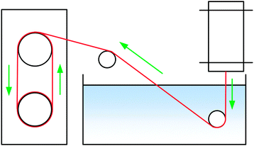
Filaments were spun with a laboratory spinning system (Fourné Polymertechnik, Germany, Fig. 2) with a 100 μm monofilament spinneret (L/D 2, Enka Tecnica, Germany). 10 g of the dope was cut, heated to make it pliable and fed into the heated cylinder. The filament was extruded over an 1 cm air gap into a water bath at 15 °C, deflected by a stationary guide at 15 cm depth, then a second guide outside the bath and from there wound onto a godet, where the filament samples were collected. The extrusion velocity was 0.04 ml min−1 (0.02 ml min−1 for [TMGH]OAc), and the godet velocity was adjusted from 5.1 to 38.2 m min−1 to give DR 1–7.5 filaments. The filaments were immersed into cold water (5 °C) to solidify the structure, washed in hot water (50 °C) for 5 min and dried and conditioned at 50% humidity and 23 °C overnight. [Emim]OAc spinning was done with a 250 μm spinneret using a larger cylinder that allowed for the required higher flow rate (0.5 ml min−1) with wash baths at 45 °C. Godet velocities were 11–30.0 m min−1, corresponding to DR 1.08–2.94. The NMMO filaments used for comparison were spun with a 18 × 100 μm multifilament spinneret.
Rheometry was done using a Paar Physica MCR 300 rheometer in a plate-plate geometry with a measuring gap of 1 mm and Peltier temperature control. For the rheology of spinning dopes, a smooth 25 mm plate was used. Master curves were produced from frequency sweep data collected at 60–120 °C in the angular frequency range of 0.1–100 s−1, using the Cross model,35 except that a power-law fluid model was used for [TMGH]OAc.
Samples of several hydration stoichiometries were prepared and gel strengths were measured with amplitude sweeps. The samples were prepared by casting a disc (10 mm by 2 mm) from the dope, then hydrating the disc with a weighed amount of water (0.25–6 molar equivalents per IL) and leaving it to equilibrate overnight in a heat-sealed polyethylene bag. The discs were trimmed with a razor blade to remove any bulge that had formed. The sample disc was pressed between serrated plates (Anton Paar PP 25/P2, plate diameter 25 mm, sample diameter 10 mm, serrations 0.5 mm) and left to relax and conform to the serrations for 10–50 minutes until the normal force stabilized, usually to half of the initial force (20–25 N). If the normal force was insufficient, only surface fracture occurred as warned by Castro et al. (2010), but with sufficient force, the discs remained elastic up to the yield point.36 Amplitude sweeps were done from 0.1 to 1000% strain at a frequency of 1 Hz at 15 °C.
There are multiple ways to define ‘gel strength’ from an amplitude sweep experiment. The simplest is the stress at the crossover point between the storage and loss moduli. However, this can overestimate the strength by ca. 40%.37 Another is the end of the linear viscoelastic range defined by the point where the storage modulus starts to reduce. With our data, this point is ambiguous, because the transition is gradual, thus this definition is not useful either. Instead, we adopt the definition of Yang et al. (1986): the yield point σy is the maximum elastic stress (G′γ) the gel can endure, calculated by σy = max(G′γ), where G′ is the storage modulus and γ is the strain.38 For almost all curves this is unambiguous. However, the curve may plateau and fluctuate, giving rise to other, confounding local maxima, thus we define it as the first apparent local maximum. The slope is very gentle, so the fit ambiguity in the yield strain (γy) is inherently large (24 ± 19%). A piecewise function consisting of a 2nd and a 3rd degree polynomial is fitted to the stress–strain curve (up to γ = 300%), and this function is used to calculate the yield strain, stress and resilience. Resilience is defined as the maximum elastic energy that can be stored in the material until the yield point. In practice, it is calculated by the numerical integration of the function U(γ) = σ(γ)Δγ up to the yield point, where Δγ = γn − γn−1. This parameter quantifies the extent of stretching that the gel can undergo before plastic deformation and damage occur.
The tensile yield strengths (σy) of gels of different water contents were calculated from the shear strength (σy,s) using the von Mises relation  as in Castro et al. (2010).36 Shear resilience (Us) was converted analogously to tensile resilience
  .
.
Calculation of incipient filament tensile strength is done by numerical integration with 100 steps using eqn (1) (derivation in ESI†):
 | (1) |
Diffusion constants of the dope were measured for both water and IL. Diffusion constants for water diffusing inwards into the filament were measured according to Biganska and Navard (2005): a drop of the dope was pressed between glass slides, then the rest of the gap was filled with water.29 Micrographs of the moving front of water were taken at intervals of 20–60 seconds using a DC300 camera (exposure 20.5 ms) on a Leica CTR MIC microscope at 5× magnification and 2088-by-1550 px resolution. Distances were measured using the Adobe PhotoShop measuring tool calibrated with a 1 mm graticule (1.1025 μm per px, Graticules Ltd, England). The equation (eqn (3)) employed by Biganska and Navard was used:
 | (2) |
Diffusion constants of the IL diffusing out from the filament were measured using a method adapted from Gavillon and Budtova (2007): a disk of the dope (2 cm by 2 mm or 0.64–0.76 g) is cast, immersed into a stirred water bath (35 g), and the concentration of the exuded solvent is measured as a function of time.31 Conductivity readings were taken with roughly logarithmically variable intervals (1 s to 10 min). The disc was protected against the magnetic stirrer with a stainless steel grid with 5 mm spacing. The concentration was monitored using an Orion Model 150 conductometer until the diffusion was completed (3–6 h). Conductivities (Table 1) were calibrated with 7 points (<11![[thin space (1/6-em)]](https://www.rsc.org/images/entities/char_2009.gif) 500 μS cm−1), and the response was linear for all solvents measured. The apparent molar conductivities of the ILs as used were calculated with Kohlrausch's law.
500 μS cm−1), and the response was linear for all solvents measured. The apparent molar conductivities of the ILs as used were calculated with Kohlrausch's law.
| Λ m [S m2 mol−1] | |
|---|---|
| NMMO·H2O | 0.03681 ± 0.00061 |
| [DBNH]OAc | 9.02 ± 0.19 |
| [emim]OAc | 9.67 ± 0.18 |
| [TMGH]OAc | 8.43 ± 0.19 |
The disc is assumed to be wide enough that lateral concentration gradients can be neglected. Thus, it is modeled one-dimensionally, and only with one exposed end, because there is no concentration gradient and thus no diffusion over its center plane. The line is divided into 100 elements, and diffusion balances are solved for each as a function of time. Diffusion of water is modeled assuming a constant Dw, and the distributions of water contents (Xw(x,t)) are calculated for each element x as a function of time.
The IL diffusion constant DIL varies with the water content; thus, a function DIL(Xw) is assumed. With the water content map in hand, the corresponding map of IL diffusion constants (DIL(x,t)) at each element x is calculated from DIL(Xw). With these data, instantaneous diffusion equations are solved for each element for the IL, and the result is integrated with eqn (1) to give a predicted degree of propagation XIL,p(t) at each time point. The system is solved in MatLab using the ode23tb solver for a given DIL(Xw). The parameters for DIL(Xw) are calculated iteratively, using the least-squared method to find the parameters for a function DIL(Xw) that fits the XIL(t) data from conductometry. For the discretization of the diffusion equation, see the ESI,† eqn (S19), (S21) and (S22).
For the simulation of an incipient filament in the bath, we consider DR 10 and Ve 0.05 ml min−1 with a d0 = 100 μm spinneret. They result in wet filament diameter d = 31.6 μm and drawn filament velocity v1 = 63.7 m min−1. These values are typical in Lyocell spinning, although they are not necessarily stable for all ILs discussed.
Results and discussion
Practical spinning
Earlier studies on spinnability concentrate on the rheology of the spin dope. For reference, the rheological properties are presented in the ESI.† The crossover point of the dynamic moduli is located at 0.76–4.06 seconds depending on the solvent. Spinning trials were conducted at a temperature where the viscosity at the crossover point (G′ = G′′) is similar to NMMO at 95 °C (3708 Pa s). For [DBNH]OAc and [emim]OAc this was 70 °C, for [TMGH]OAc 90 °C. Rheology does not explain the observed large differences in spinnability in all cases. However, [TMGH]OAc is not a Cross fluid, but a power law fluid (power law index 0.5) within the measured range (see ESI,† Fig. S1 and Table S2).Demonstrative spinning (Table 2) for 13% solutions was conducted in order to relate the rheological and diffusion results and simulations to practical experience. A bath temperature of 15 °C was chosen based on earlier experiments, where the cool bath was found to produce stronger filaments.22 Other experiments were conducted at the same temperature. Filament properties are detailed in the ESI,† Table S3. Spinnability was good for [DBNH]OAc (up to DR 7.5), but poor for [TMGH]OAc (only DR 2). [Emim]OAc could not be spun with a 100 μm spinneret, but could be spun up to DR 2.9 with a 250 μm spinneret at 70 °C. [DBNH]OAc gave high-tenacity filaments at 70 °C as reported earlier.9,22,40 [TMGH]OAc (80 °C) filaments could be initially taken up and fibers collected, but it would break within seconds, which suggests draw resonance as a possible breach mechanism. A draw resonance is a dynamic instability that results in cohesive or other breach after a few seconds. A small defect or overthinned section in the jet travels forward into the regeneration bath. There, it undergoes excessive plastic deformation in draw. Consequently, the newly extruded portion of the jet right before it on the spinline is stretched with less force, and it remains thicker than intended. The thicker part travels forward, being stretched less than usual, transmitting more force upstream from the godet toward the extruder and causing another over-thinning cycle. The resonance will eventually lead to a break within a few cycles, which is what is observed in practice for [TMGH]OAc.25,41 [emim]OAc (70 °C) underwent an obvious telescope-type breach: the skin ruptured, causing a visually apparent necking deformation several centimeters long, leading to a filament break.
| Spinning solvent | d 0 [μm] | T extr [°C] | T bath [°C] | D Rmax | Titer [dtex] | Tenacity [cN tex−1] |
|---|---|---|---|---|---|---|
| a d 0, spinneret diameter; Textr, extrusion temperature; Tbath, regeneration bath temperature; DRmax, highest draw ratio spun. | ||||||
| [DBNH]OAc | 100 | 70 | 15 | 7.5 | 3.0 ± 0.9 | 38.5 ± 8.4 |
| NMMO·H2O | 100 | 95 | 15 | 6.2 | 3.7 ± 0.7 | 31.2 ± 6.6 |
| [TMGH]OAc | 100 | 80 | 15 | 2.0 | 15.5 ± 0.9 | 10.9 ± 1.1 |
| [emim]OAc | 250 | 90 | 45 | 2.9 | 44.4 ± 1.7 | 13.9 ± 1.6 |
Resilience of the partially regenerated dopes
When the jet enters the bath, water diffuses radially inwards. The hydration of the ionic liquid causes the desolvation and regeneration of the cellulose into a hydrated cellulose gel, which further gains permanent strength on drying. The rheology changes from that of the dope into a strong gel. However, the rheology of the intermediate, partially hydrated states is an open question, and phenomena that could weaken the filament could occur. Therefore, strain at yield and gel strength were measured for samples of dopes hydrated by 0.5–5 eq. water, and the gel resiliences calculated (Fig. 3). Yield strain is 200–400% for unregenerated dopes, but ca. 100% and largely constant for dopes with 0.5 eq. water or more. While gel strengths are monotonically rising, resiliences display an intermediate minimum at 0 to 1–2 water equivalents in the IL dopes (Fig. 3). For [emim]OAc, even the gel strength has a minimum at this range (ESI,† Fig S7), and the resilience minimum is very low.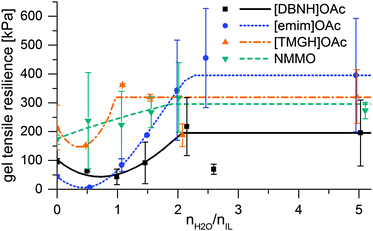 | ||
| Fig. 3 Modulus of elastic resilience vs. water added and the interpolation functions used for modeling. | ||
Diffusion of water
Diffusion of water into the IL solution was found to follow eqn (2) accurately (Fig. S5, ESI†) implying a constant Dw, with 0.5–0.9% error in the fit. It was smaller for [emim]OAc dopes than for [DBNH]OAc and [TMGH]OAc dopes (Table 3).Strength of the incipient filament
Incipient filament strength can be predicted by calculating the distribution of water from the water diffusion constants Dw, then mapping the rheological strength data to the water content distribution of a filament at each time point and corresponding depth in the bath. Results of the simulation are presented in Fig. 4. These are minimum strengths, as the rheological data used to predict them have not been collected on a stretched jet, but on unstretched solutions with no induced orientation. Also, they do not reach final fiber strengths, because fiber strength is further increased in the drying step by crystallization. [TMGH]OAc, NMMO and [DBNH]OAc reach high strengths faster than [emim]OAc, although the final strength of [DBNH]OAc is lower. For a constant Dw, the depth where regeneration is complete is independent of DRi.e. v1 at a constant ve, but depends linearly on ve, d0 and Dw−1 (see ESI,† for analytical derivation).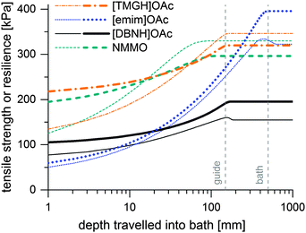 | ||
| Fig. 4 Simulated minimum incipient filament strengths (thin lines) and resiliences (thick lines) at Ve = 0.05 ml min−1 at DR = 10 in kPa as a function of distance travelled in a water bath. | ||
Thus, the length of the section with incomplete regeneration is longer for an [emim]OAc incipient filament, as compared to other solvents. However, the total strength increases monotonically (Fig. 4). This is even the case for [emim]OAc, because the formed skin contributes much more to the total strength than the weakened core reduces it. Thus, [emim]OAc incipient filaments reach good strengths within centimeters, well before the guide, which would suggest stable spinning also for [emim]OAc. There is also a radial variation in the incipient filament structure. For other ILs, the gel strength monotonically increases as a function of water content, but for [emim]OAc it does not. For [emim]OAc, although the incipient filament does have a strong skin, the resilience in the core is very low at around 300 mm (Fig. 5). Both yield strain and stress decrease at 0.5 nH2O/nIL, giving a tensile resilience of only 6.1 kPa, lower than the resilience before hydration (44 kPa) or resilience at 1.0 nH2O/nIL (84 kPa). The same behavior does appear for other ILs, but in a less dramatic way (see Fig. 1).
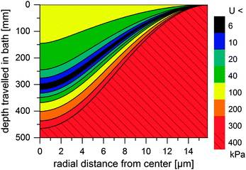 | ||
| Fig. 5 Simulated minimum resilience (U, in kPa) for an [emim]OAc incipient filament as a function of distance travelled in a water bath. | ||
According to Chen et al. (2010), breaks begin in the center of a cylinder.39 The hydration front of the weak material moves inward radially and reaches the center. There, a telescopic-type breach is initiated: failure of the core overstresses the partially regenerated skin, which ruptures, leading to progressive thinning and ultimately to a break.24 This has been previously observed in wet spinning.26 In a classical telescope breach, coaxial layers of different speed or composition in the jet separate, which requires high deformation rates. Here, the incipient filament is unstable because upon excess thinning, the fluid core is compressed. The pressure translates to flow away from the thin section, which results in even more thinning, making the system dynamically unstable.
In principle, the solution could be spinnable if mixed already with 0.5–1.0 eq. water, so that its increase in strength is monotonic with higher water content. This would avoid the problem of a weaker core. Unfortunately, however, adding 0.5 or 1.0 nH2O/nIL water to the dope did not make it spinnable. The solution viscosity decreased, and when spinning at the equivalent viscosity point of 40–50 °C, the incipient filament was still too weak. Therefore, spinning was done with a 250 μm spinneret to get [emim]OAc reference fibers. For [TMGH]OAc, there are no problems with strength or resilience, and other reasons for its poor spinnability must be sought.
Diffusion of ionic liquids and washing the filament
The diffusion of ILs into the aqueous phase was measured. The single DIL-value equation assuming an effective diffusion constant according to Crank (1975) or its approximations does not fit our data.31,42 Instead, we solve the differential diffusion equation numerically allowing for a DIL value that varies with water content from DIL,i to DIL,f. Diffusion constants are functions of microviscosities, thus the true diffusion constant should be a function of water content. Since calculating diffusion constants merely from the amount of exuded material is an ill-posed inverse problem, the function DIL(Xw) cannot be calculated exactly. Instead, an assumed, but physically reasonable DIL(Xw) function shape is employed. We assume a threshold water content below which DIL = 0, followed by the following equation (see ESI,† for derivation): | (3) |
Results for the fit are shown in Fig 6, 7 and Table 3. For NMMO, Liu and Hu (2006) observed the DNMMO,i (7 × 10⁻¹⁰ m2 s−1) and apparent DNMMO (4–8 × 10⁻¹¹ m2 s−1) in a spinning apparatus.30 Our results are in good agreement (7.1 × 10⁻¹⁰ m2 s−1 and 5.38 × 10⁻¹¹ m2 s−1, respectively, Table 3). However, only a water content-dependent DIL(cw) (Fig. 7) gives a good fit to the observed degree of propagation XIL(t) (Fig. 6). For each IL, the initial and final IL diffusion constants (DIL,i and DIL,f) are higher than apparent Dw, except for DIL,f in [emim]OAc and [TMGH]OAc dopes.
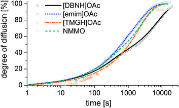 | ||
| Fig. 6 Progress of the diffusion of ILs from a cast disc of the dope into a stirred volume of water at 15 °C, observed by measuring the conductivity of the water. | ||
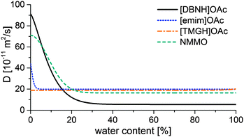 | ||
| Fig. 7 Functions of the IL diffusion constants vs. water content that fit the data in Fig. 4. | ||
The solution suggests that the hydration front moves slower than the ionic liquid diffuses behind the hydration front. Likely, the actual Dw also varies with water content. However, Dw for hydrated dopes cannot be directly observed, because the hydration process is slower than the diffusion of either water or ILs and consequently rate-limiting. Thus, the hydration controls the rate of diffusion front progression, which our Dw experiment measures. Dw depends on the rate of the hydration reaction. The hydration of all cellulose solvents is thermodynamically favorable, because of the specific interaction between the basic cation and amphoteric water. However, the nature of the transition state that controls the rate depends on the identity of the IL and possibly the structure of the solution.
D IL changes substantially for the good solvents [DBNH]OAc and NMMO across a wide range, but remains nearly constant for [emim]OAc and [TMGH]OAc (Fig. 7). During the regeneration, a gelatinous regenerated polymer network forms. It comprises the main resistance to further diffusion. The IL molecules have similar sizes so the differences must be caused by the differences in the gel structure. For [DBNH]OAc the diffusion in the fully hydrated gel is slower than for other solvents, implying the presence of an especially dense, collapsed polymer structure. Whereas, a DIL value that is constant across water contents shows that the microviscosity does not change. This implies that the gel network is already in place in the non-regenerated dope and does not physically move during regeneration, because regeneration is not seen to introduce more resistance to diffusion. In spinning, plastic deformation to align the polymer chains, followed by the formation of cohesive intermolecular bonds during drying, is necessary for filament strengthening. A pre-existing gelatinous network impedes both steps and leads to poor spinnability and low fiber strength. This conclusion is supported by both dope rheometry and fiber properties: for [TMGH]OAc, the non-regenerated dope is already gelatinous according to rheometry (see ESI†), while the cellulose chains do not reveal any orientation (see below).
Concerning the practical implications of the results, gel strength experiments (Fig. S8, ESI†) suggest that the diffusion of ionic liquids out from the fiber is unlikely to be a strength-limiting factor. There are no major changes in strength from 2.5 to 5.0 equivalents added water, which represent regenerated and washed states, respectively. On the spinline, the half-meter submersion length is sufficient to remove 60% of [DBNH]OAc and 90% of other solvents.
Orientation and spinnability
In melt spinning and dry jet-wet spinning, the orientation of polymer molecules provides dynamic stability. Fluctuations in the drawing force are reflected in fluctuations in stress and thus filament strain, causing the formation of thin weak points and the destabilization of spinning. However, for a polymer, strain hardening compensates for the loss of strength at the thin sections: the excess stress improves the orientation of the stressed jet element. This increases its Trouton viscosity, so that deformation is smaller, and stress is distributed along the filament instead of at a single point. Strain hardening provides negative feedback against rupture.25,41 However, this critically depends on the ability of the polymer solution to gain and retain polymer chain orientation.The low resilience in [emim]OAc fibers suggests that orientation in [emim]OAc dopes is gained and retained poorly. Orientation may develop only in high extensional shear, therefore the commonly used rotational rheometry with low shear does not reveal this phenomenon. Although the low-shear rheology of [emim]OAc dopes is similar to that of other dopes with good spinnability, [emim]OAc jets remain fluid – like the core of viscose fiber – due to their lower Dw and melting point, both before and in the bath. For [TMGH]OAc, gel-like behavior suggests that the solution behaves as a permanent network whose orientation is low at DR 2. In such systems, any disturbance can cause ruptures or draw resonance.23
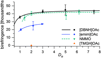
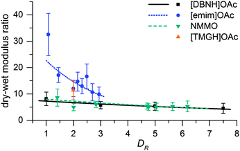
Fiber properties do confirm the hypothesis (Fig. 8 and 9). For [DBNH]OAc and NMMO·H2O, birefringence is high from the start, and levels off at DR 3–5. [Emim]OAc gains orientation at the same rate, but has low birefringence at DR 1, and can only reach Δn = 0.0270 ± 0.0007 (43.6 ± 1.2% orientation) at DR 3 where it breaks. No reaction to polarized light, and thus no birefringence was found for [TMGH]OAc at DR 2. The dry-wet modulus ratio (DWMR), which is a measure of the orientation of amorphous domains, is illustrated in Fig. 9.22,28 Again, [DBNH]OAc and NMMO·H2O give identical results, while [emim]OAc and [TMGH]OAc filaments have obviously lower orientations.
In terms of strength, [TMGH]OAc fibers combine low tenacity (10.9 ± 1.1 cN tex−1) with a moderate elongation at break (9.3 ± 1.0%), which also supports the conclusion of a broken fiber structure with an interrupted load path. Whereas, at DR 2, [emim]OAc fibers (spun with a 250 μm spinneret) have the same tenacity (11.6 ± 0.7 cN tex−1) with a very high elongation at break (41.0 ± 3.8%), suggesting an amorphous but solid structure. NMMO and [DBNH]OAc have good tenacities (24.6 ± 3.4 cN tex−1 at DR 2 and 35.1 ± 4.4 cN tex−1 at DR 3, respectively) with moderate elongations at break (9.9 ± 2.3% and 9.7 ± 1.2%, respectively), suggesting a strong, well-oriented structure. (See ESI,† Table S3 for all fiber strength data.)
Conclusions
Spinning experiments showed that cellulose solutions in [emim]OAc (15% cellulose) and [TMGH]OAc (13%) are poorly spinnable, while those in [DBNH]OAc and NMMO (13%) can be spun with high draw ratios (DR 12.5) with a 100 μm spinneret. In dope samples, the diffusion constants of [DBNH]OAc and NMMO·H2O were initially high and fell by 93% and 77% respectively within the first 20 m% of hydration, which suggests that a strong intermolecular network forms during regeneration. For [emim]OAc, the fall was less pronounced at 55% and occurred within 5 m%. In contrast, the diffusion constant of [TMGH]OAc was constant across water contents, suggesting that [TMGH]OAc solutions are gelatinous, poorly mechanically orientable networks before and during regeneration. Rheometry revealed that [TMGH]OAc was gelatinous even at low shear rates, and as a power-law fluid it was subject to draw resonance.25 [TMGH]OAc fibers prepared at a DR of 2 had a low strength (10.9 ± 1.1 cN tex−1) and resilience (0.54 ± 0.29 MJ m−3) and a moderate elongation at break (9.3 ± 1.0%). With no measurable birefringence, they were solidified gels. [Emim]OAc incipient filaments failed with a telescope-type breach, because there was a zone of weaker gel with 0–1 eq. water progressing towards the center of the fiber. Simulations suggest that the front of the low-resilience material reaches the core, where a runaway telescope breach can begin. Like viscose filaments, filaments spun from [emim]OAc had low orientation but high elongation, and could be spun only at low draw ratios with a 250 μm spinneret. The gel strength and resilience minimum at 0.5 water equivalents suggest that part of the deformation also occurs in a semi-solidified state. In contrast, [DBNH]OAc- and NMMO-based dopes produced highly oriented fibers at already low draw ratios, their properties improve with DR. The conclusion is that a good spinning solvent must also be a good solvent whose regeneration solidifies the structure, thus enabling gain and retention of orientation. Gelatinous dopes that already have a gel network before regeneration or dopes that weaken upon the addition of water are poor spinning solvents.Acknowledgements
The authors wish to thank Tekes – the Finnish Funding Agency for Innovation and Finnish Bioeconomy Cluster FIBIC Ltd for funding. Arno Parviainen, Dr Alistair King and Prof. Ilkka Kilpeläinen provided [DBNH]OAc. Filtration and spinning equipment was constructed or modified by Seppo Jääskeläinen and his team.Notes and references
- R. P. Swatloski, S. K. Spear, J. D. Holbrey and R. D. Rogers, J. Am. Chem. Soc., 2002, 124, 4974–4975 CrossRef CAS PubMed
.
- A. Brandt, J. Grasvik, J. P. Hallett and T. Welton, Green Chem., 2013, 15, 550–583 RSC
.
- A. A. Aerov, A. R. Khokhlov and I. I. Potemkin, J. Phys. Chem. B, 2006, 110, 16205–16207 CrossRef CAS PubMed
.
- X. Gong, S. Frankert, Y. Wang and L. Li, Chem. Commun., 2013, 49, 7803–7805 RSC
.
- X. Gong, A. Kozbial and L. Li, Chem. Sci., 2015, 6, 3478–3482 RSC
.
- R. C. Remsing, R. P. Swatloski, R. D. Rogers and G. Moyna, Chem. Commun., 2006, 1271–1273 RSC
.
- T. V. Doherty, M. Mora-Pale, S. E. Foley, R. J. Linhardt and J. S. Dordick, Green Chem., 2010, 12, 1967 RSC
.
- L. K. J. Hauru, M. Hummel, A. W. T. King, I. A. Kilpeläinen and H. Sixta, Biomacromolecules, 2012, 13, 2896–2905 CrossRef CAS PubMed
.
-
M. Hummel, A. Michud, M. Tanttu, S. Asaadi, Y. Ma, L. K. J. Hauru, A. Parviainen, A. W. T. King, I. Kilpeläinen and H. Sixta, Adv. Polym. Sci., Springer, Berlin, Heidelberg, 2015, vol. 307 Search PubMed
.
- G. Laus, G. Bentivoglio, H. Schottenberger, V. Kahlenberg, H. Kopacka, T. Röder and H. Sixta, Lenzinger Ber., 2005, 84, 71–85 CAS
.
- G. Jiang, Y. Yuan, B. Wang, X. Yin, K. Mukuze, W. Huang, Y. Zhang and H. Wang, Cellulose, 2012, 19, 1075–1083 CrossRef CAS
.
- R. Rinaldi, Chem. Commun., 2011, 47, 511 RSC
.
- H. Sixta, A. Michud, L. Hauru, S. Asaadi, Y. Ma, A. W. T. King, I. Kilpeläinen and M. Hummel, Nord. Pulp Pap. Res. J., 2015, 30, 043–057 CAS
.
- F. M. Hämmerle, Lenzinger Ber., 2011, 89, 12–21 Search PubMed
.
-
D. L. Johnson, US Pat., 3,508,941, 1970 Search PubMed
.
- H. P. Fink, P. Weigel, H. J. Purz and J. Ganster, Prog. Polym. Sci., 2001, 26, 1473–1524 CrossRef CAS
.
- G. Viswanathan, S. Murugesan, V. Pushparaj, O. Nalamasu, P. M. Ajayan and R. J. Linhardt, Biomacromolecules, 2006, 7, 415–418 CrossRef CAS PubMed
.
- H. Zhang, Z. G. Wang, Z. N. Zhang, J. Wu, J. Zhang and J. S. He, Adv. Mater., 2007, 19, 698–704 CrossRef CAS
.
- B. Kosan, C. Michels and F. Meister, Cellulose, 2008, 15, 59–66 CrossRef CAS
.
- N. Sun, R. P. Swatloski, M. L. Maxim, M. Rahman, A. G. Harland, A. Haque, S. K. Spear, D. T. Daly and R. D. Rogers, J. Mater. Chem., 2008, 18, 283–290 RSC
.
- T. Cai, Y. M. Wang, Y. R. Yang, M. Wei and M. K. Wang, Appl. Mech. Mater., 2013, 423–426, 370–372 CrossRef CAS
.
- L. K. J. Hauru, M. Hummel, A. Michud and H. Sixta, Cellulose, 2014, 21, 4471–4481 CrossRef CAS
.
-
A. Ziabicki, Fundamentals of Fibre Formation, John Wiley & Sons, London, 1976 Search PubMed
.
- T. Gries, B. Wirth, M. Warnecke, B. Schmenk and G. Seide, Chem. Fibers Int., 2011, 61, 38–39 Search PubMed
.
- R. J. Fisher and M. M. Denn, AIChE J., 1976, 22, 236–246 CrossRef CAS
.
- D. R. Paul, J. Appl. Polym. Sci., 1968, 12, 2273–2298 CrossRef CAS
.
-
M. Dubé and R. H. Blackwell, Proceedings of the International Dissolving and Speciality Pulps Conference, TAPPI, Boston, 1983, p. 111–119 Search PubMed
.
- H. A. Coulsey and S. B. Smith, Lenzinger Ber., 1996, 75, 51–61 Search PubMed
.
- O. Biganska and P. Navard, Biomacromolecules, 2005, 6, 1948–1953 CrossRef CAS PubMed
.
- R. Liu and X. Hu, Ind. Eng. Chem. Res., 2006, 45, 2840–2844 CrossRef CAS
.
- R. Gavillon and T. Budtova, Biomacromolecules, 2007, 8, 424–432 CrossRef CAS PubMed
.
- J. Song, B. Cheng, X. Jie, Y. Liang, F. Lu and F. Zhang, e-Polymers, 2011, 11, 401 CrossRef
.
- V. VanRheenen, D. Y. Cha and W. M. Hartley, Org. Synth., 1978, 58, 43 CrossRef CAS
.
- A. W. T. King, J. Asikkala, I. Mutikainen, P. Järvi and I. Kilpeläinen, Angew. Chem., 2011, 123, 6425–6429 CrossRef
.
- R. J. Sammons, J. R. Collier, T. G. Rials and S. Petrovan, J. Appl. Polym. Sci., 2008, 110, 1175–1181 CrossRef CAS
.
- M. Castro, D. W. Giles, C. W. Macosko and T. Moaddel, J. Rheol., 2010, 54, 81–94 CrossRef CAS
.
- H. J. Walls, S. B. Caines, A. M. Sanchez and S. A. Khan, J. Rheol., 2003, 47, 847–868 CrossRef CAS
.
- M. C. Yang, L. E. Scriven and C. W. Macosko, J. Rheol., 1986, 30, 1015–1029 CrossRef CAS
.
- X. X. Chen, P. D. Wu, J. D. Embury and Y. Huang, Modell. Simul. Mater. Sci. Eng., 2010, 18, 025005 CrossRef
.
-
L. K. J. Hauru, M. Hummel, A. Michud, S. Asaadi and H. Sixta, Proceedings of the 7th Aachen-Dresden International Textile Conference, Aachen, 2013, P7 Search PubMed
.
- A. T. Serkov and V. V. Skorobogatykh, Fibre Chem., 1995, 27, 413–418 CrossRef
.
-
J. Crank, The Mathematics of Diffusion, Oxford University Press, Oxford, 2nd edn, 1975 Search PubMed
.
Footnote |
| † Electronic supplementary information (ESI) available. See DOI: 10.1039/c5sm02618k |
| This journal is © The Royal Society of Chemistry 2016 |


