
 Open Access Article
 This Open Access Article is licensed under a
 Creative Commons Attribution 3.0 Unported Licence
Continuous flow Buchwald–Hartwig amination of a pharmaceutical intermediate†
Polina
Yaseneva
a,
Paul
Hodgson
a,
Jacek
Zakrzewski
a,
Sebastian
Falß
b,
Rebecca E.
Meadows
c and
Alexei A.
Lapkin
*a
aDepartment of Chemical Engineering and Biotechnology, University of Cambridge, Cambridge CB2 3RA, UK. E-mail: aal35@cam.ac.uk; Fax: +44 (0)1223 334796
bINVITE GmbH, Chempark Leverkusen, 51373 Leverkusen, Germany
cPharmaceutical Development, AstraZeneca, Silk Road Business Park, Macclesfield SK10 2NA, UK
First published on 23rd November 2015
Abstract
A flow process for direct amination of a pharmaceutically relevant substrate using a Pd-NHC based catalyst was demonstrated in a lab-scale mini-plant and in a pilot-scale plant. The lab-scale mini-plant was used to determine catalyst stability under recycling conditions. Results in the mini-plant have shown the maximum space–time yield between the three types of reactor systems: a batch reactor, a mini-plant and a pilot plant. A comprehensive life-cycle assessment study of the synthesis of organometallic catalysts and their impact on the overall LCA of flow vs. batch syntheses was developed. Combined with a simplified economic analysis, the LCA study confirmed the benefits of switching to flow.
Introduction
It has now been recognised for some time that conventional methods of synthesis used in pharmaceutical and speciality chemicals industries, that are based predominantly on stoichiometric reactions and batch processing, almost inevitably result in significant amounts of waste per unit mass of a product.1 This stems from very traditional approaches to synthesis development and scale-up and the significant sunk investment into batch manufacturing equipment in industry: stoichiometric synthesis methods and batch manufacturing mode frequently lead to low space–time yields, complex product isolation and purification processes, batch-to-batch variability, significant quantities of solvents for cleaning, etc. All these factors contribute to environmental burden, poor image of the chemical industry in society, and loss of competitiveness of the industry. Rapid development of green chemistry and green engineering over the past two decades has clearly demonstrated the benefits of cleaner catalytic chemistry and of the more advanced continuous flow processes for pharmaceutical and fine chemistry industries.2–9 A number of continuous flow processes have reached maturity and were commercialised at industrial scale. A good example is Sanofi–Genzyme’s continuous process for manufacture of sevelamer carbonate (Renvela), making use of advanced reactor technology and real time process monitoring.In many cases, batch processes make perfect sense, but continuous manufacturing and in particular continuous catalytic processes offer an additional technique to pharmaceutical and fine chemistry manufacturing. Typically, continuous catalytic processes realise better safety and product consistency at higher volumetric productivities. However, development of continuous catalytic processes for complex reactions, typical of pharmaceutical and fine chemistry industries, requires a very different approach to the development of synthetic methods and to their scale-up, when these two steps are performed simultaneously, since new reactor concepts may offer new possibilities for chemical synthesis and vice versa new discoveries in catalysis will affect the requirements for reactor design.10,11
One such complex reaction of significant importance in the pharmaceutical and fine chemistry industries is the C–N coupling of amines with organohalides, Buchwald–Hartwig amination, catalysed by palladium–ligand complexes.12,13 The reaction of direct cross coupling is highly sensitive to the nature of catalytic metal, ligand structure, nature of base and solvent.14 The production of stoichiometric amounts of an insoluble inorganic salt in the reaction presents a particular problem for potential continuous flow processes. Nevertheless, there are several literature examples of Buchwald–Hartwig amination reactions performed in continuous flow microreactors, although most of them have only been run for limited periods of time. Amination of p-bromotoluene with piperidine catalysed by Pd(OAc)2/DavePhos/NaOtAm in xylene was performed in a Cytos reactor, apparently without reactor clogging with the by-product NaBr.15 A range of substrates for amination reaction was demonstrated with the Pd/BrettPhos/NaOtBu system in a microreactor with ultrasound to prevent reactor clogging.16 Unavoidable formation of solids that leads to blockage of flow reactors by particle aggregation and surface fouling mechanisms, however, remains a significant issue to adoption of flow technology for such reactions.17
Recently, highly active N-heterocyclic carbene (NHC) ligand-based palladium catalysts have been developed for C–N coupling reactions.18,19 The high reaction rates with the new catalysts make the process more attractive to continuous flow, due to the significant reduction in residence time and the corresponding reactor size required. A continuous flow amination in a microreactor using an NHC catalyst was successfully demonstrated with DME as a solvent and using model substrates.20 However, the use of DME for industrial applications is undesirable,21 as it leads to a complex product stream miscible with water and, consequently, difficult catalyst recovery. Demonstration of the reaction using substrates that are close to the industrially-relevant molecules is preferable.
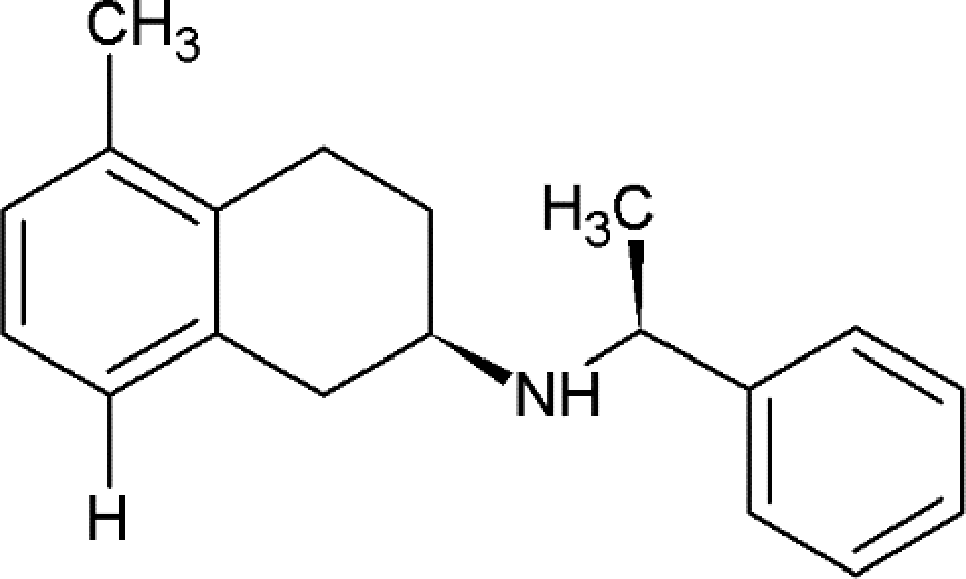
An example of an industrially relevant substrate for B–H amination is a published batch process developed within AstraZeneca, see Scheme 1.22 Conversion of this reaction into a viable flow process utilising one of the more active Pd-NHC catalysts was one of the several case studies of a recently completed large integrated EU FP7 project SYNFLOW (www.synflow.eu). Both batch and flow process conditions are shown in Scheme 1. Detailed description of the catalyst development is given elsewhere,18,23 and a detailed study of the reaction in a laboratory microreactor is described in ref. 24. Here we focus on two aspects of the process: demonstration of catalyst recycling under flow conditions and developing a detailed life-cycle assessment of the flow process, including synthesis of the catalysts to provide a quantitative basis for comparison of the flow and the batch processes.
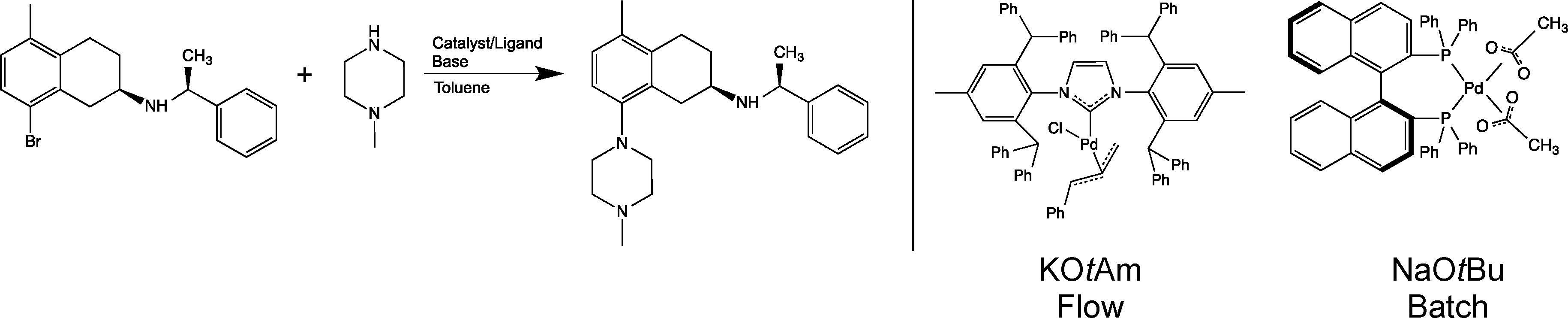 | ||
| Scheme 1 Buchwald–Hartwig amination reaction studied in this work (left). Flow and batch process conditions (catalyst and base) are also shown (right). | ||
Conversion of batch processes into flow mode frequently requires change of solvents, reagents and catalysts. The benefit of flow is then quantified in terms of performance indicators (throughput, selectivity, metal contamination), economic indicators, and environmental indicators. In carrying out a cost comparison of the existing batch process with the new process in flow, there were a number of difficulties: the existing catalyst and ligand (Pd(OAc)2 and BINAP) are commercially available at bulk scale and, as a result of this, relatively cheap. However, the novel [Pd(IPr*)(cin)Cl] catalyst is not, as yet, commercially available on a large scale, and therefore, direct comparison of the cost of the two catalytic systems would not be representative of a genuine manufacturing situation. The cost of [Pd(IPr*)(cin)Cl] on industrial scale has therefore had to be estimated from the cost of similar catalysts available on bulk scale. The change of catalyst necessitates the change of base and with this comes additional economic and waste factors that need to be considered.
When considering the two processes, the biggest change is the change of catalyst. There is no agreement within the literature whether a catalyst contribution to environmental impacts of the overall process is significant or not. The basis for such evaluation is the methodology of life cycle assessment (LCA). For some assessed catalytic processes, the contribution of a catalyst is negligible,25 while for some other cases the contribution of a catalyst to environmental impacts reaches almost 100%.26 In many cases of organometallic catalysis, the turn-over-numbers (TONs) attained are not very high, but ligands used are very complex. In these cases, the impact of a catalyst on the overall environmental performance of a process may, potentially, be significant. The lack of understanding of this significance was the motivation to develop a detailed LCA case study of the synthesis of two molecularly-defined catalysts and to include them in comparative LCA of the overall process.
Evaluation of environmental impacts of technology can be performed within different system boundaries: only considering a process itself, the so-called gate-to-gate boundary, considering the contribution to impacts from transport and manufacture of all material inputs into the technology starting from raw materials, the so-called cradle-to-gate boundary, or even accounting for the impacts of the use of products and their post-use fate, the so-called cradle-to-cradle boundary. The last two types of evaluation, performed within very wide system boundaries, are the domains of life cycle assessment. Changes within processes, such as replacement of catalysts, change of base, and change in the material inputs into the process, will necessarily result in changes to environmental impacts of the supply chain preceding the actual process. Therefore, in this case, LCA within the cradle-to-gate system boundary is the most appropriate methodology for comprehensive evaluation of environmental performance of technology. LCA methodology enables attribution of impacts to different stages of the process, such as different sources of energy or materials used. Therefore, when we compare a batch process that was optimised for one type of catalyst with a flow process, that was optimised for another catalyst, the changes in material flows prior to the actual new chemical synthesis are rather complex. Many environmental and toxicity impacts associated with chemical species frequently arise in the processes of their manufacture rather than at the stage of their use. Hence, the changes in environmental impacts of processes that occur upon substitution of chemicals used within the process are not intuitive and their proper evaluation requires cradle-to-gate or even cradle-to-cradle LCA.
There are only a few LCA studies of inorganic catalysts for different chemical processes in the literature,25–29 but to the best of our knowledge our study is the first comprehensive LCA of a metal organic catalyst. The difficulty with conducting LCA of complex organic molecules is primarily the lack of information on life cycle inventories: the impacts of all the stages of synthesis of all molecules involved in the manufacture of a catalyst. As a consequence, industry developed a number of streamlined tools to support decision-making in developing cleaner processes.30–32 However, the use of short-cut methods or avoiding the use of comprehensive LCA means that insights into detailed understanding of the origin of impacts cannot be developed. Here we describe the LCA results based on the developed full inventories of synthesis of the Pd(OAc)2/BINAP and the NHC-based palladium catalysts for the reaction of interest, the developed and studied lab-scale flow reactor system for catalyst recycling and the pilot-scale flow experimental data.
Materials and methods
General procedure for Buchwald–Hartwig amination under batch conditions
The batch procedure is described in detail elsewhere.22 Here we describe it briefly for the purpose of comparison with the flow procedure, since both were coded in the life-cycle assessment model. To a batch reactor containing palladium acetate (0.47 mol%) and (R)-BINAP (0.2 mol%) stirred in toluene at 40 °C, aryl bromide substrate (1 equivalent, corresponding to 0.5 M in the reactor), N-methylpiperazine (2 equivalents) and sodium tert-butoxide (1.4 equivalents) are added. The mixture is stirred at 100 °C until full conversion is reached. It is then cooled to room temperature. After the stirrer is turned off and the phases are separated, the water phase is removed and acetic acid is added to the residual organic phase at pH below 6 and stirred for 20 minutes. After that, the phases are separated within one hour, the product being in the water phase. In this reaction apart from the desired product, tert-butyl alcohol and sodium bromide salt are also formed.Lab scale mini-plant recycling experiments
The flow process using the Pd-NHC catalyst is shown in Scheme 1 and was optimised for potassium tert-amylate as a base. In order to justify the assumption of catalyst recyclability in the flow conditions for LCA process models, a lab scale flow mini-plant was set-up, see ESI† for details, Fig. S1. Three separate streams were fed to a PTFE coil reactor of 10.9 mL volume and 1.5 mm internal diameter, placed into an ultrasonic bath kept at 70 °C for the reaction in order to prevent solids formation and reactor clogging. Stream A: Pd-NHC catalyst in toluene, 1 mol%, and GC internal standard mesitylene. Stream B: aryl bromide (1.0 equivalent, corresponding to 0.53 M in the reactor) and N-methylpiperazine (1.15 equivalents) in toluene. Stream C: potassium tert-amylate in toluene, 1.7 M. Feed vessels were kept under inert conditions. Solutions A and B were pumped using Vapourtec peristaltic pumps and solution C was pumped using a Harvard PHD Ultra syringe pump. The residence time of the reaction was 10 min, and the reaction was run for 1 h. The product stream was mixed with acetic acid solution (1.35 M concentration of AcOH feed, 1![[thin space (1/6-em)]](https://www.rsc.org/images/entities/char_2009.gif) :1 v:v ratio mixing with product stream). After phase separation, the organic phase was returned to the vessel with fresh catalyst. This resulted in continuous dilution of the catalyst feed as excess toluene was not removed. The dilution effect had no consequences on reaction performance within the timeframe of experiments done.
:1 v:v ratio mixing with product stream). After phase separation, the organic phase was returned to the vessel with fresh catalyst. This resulted in continuous dilution of the catalyst feed as excess toluene was not removed. The dilution effect had no consequences on reaction performance within the timeframe of experiments done.
Pilot scale Buchwald–Hartwig amination in flow
In the flow demonstration process aryl bromide substrate (1 equivalent, corresponding to 0.23 M in the reactor) was mixed with N-methylpiperazine (1 equivalent) and potassium tert-amylate as a base (1.5 equivalent, added as a 25 wt% solution in toluene, Sigma-Aldrich), and Pd-NHC catalyst was added, to achieve a concentration in the reactor of 0.5 mol%; toluene (99.8%, anhydrous, Sigma-Aldrich) was used as a reaction solvent. Insoluble potassium bromide salt was formed as a result of the reaction.A demonstration unit for the Buchwald–Hartwig amination case study within the SYNFLOW project was constructed at INVITE facility (http://www.invite-research.com/en/welcome-to-the-invite-research-center.html), see ESI,† Fig. S2, for details. In order to achieve a maximum degree of flexibility, all reagents were fed separately. Furthermore, all feed lines were connected to the toluene feed vessel for commissioning and start-up. All feed vessels were kept under inert conditions as the reaction is sensitive to moisture and air, and the whole system was flushed with acetone and degassed prior to experiments.
The set-up for the actual Buchwald–Hartwig amination was as follows: a modular, agitated reactor consisting of five stages (with a volume of 100 mL each) was used for the reaction. The substrates and the catalyst solution were fed to the top reactor stage. The base was then added to the second stage of the reactor mainly to prevent solids from damaging the magnetic drive on top of the first stage (the reactor was run liquid-full). As the Buchwald–Hartwig amination is an exothermic reaction, cooling was provided by means of a double-jacket. The temperature inside the reactor was kept at 60–70 °C during the reaction and monitored by temperature sensors in each reaction chamber. All experiments were run at a total flow rate of 1 L h−1 of organic phase, which corresponds to a residence time of 24 min (100 mL per chamber, but the base was only added to the second chamber so that the reaction takes place in a total volume of 400 mL).
In the work-up procedure, the reactor effluent was mixed with an aqueous solution of acetic acid in order to extract the protonated form of the product at pH ca. 5.3 and optimal temperature for extraction of 30 °C. Catalyst recycling was not investigated in the demonstration experiments.
Product analysis
H NMR, Bruker AM 400. 1H NMR (400 MHz, CDCl3, 25 °C, TMS): δ 10.36 (broad, 1H), 10.08 (broad, 1H), 7.71–7.74 (m, 2H), 7.43 (t, J = 7 Hz, 2H), 7.34–7.38 (m, 1H), 6.94–6.95 (m, 2H), 6.78–6.81 (m, 1H), 4.49–4.54 (m, 1H), 3.35–3.51 (m, 2H), 3.03 (broad, 1H), 2.85–2.91 (m, 1H), 2.40–2.50 (m, 2H), 2.17–2.30 (m, 1H), 2.14 (s, 3H), 2.03 (d, J = 7 Hz, 3H).22
The palladium concentration in the product stream was checked using an ICP-OES iCAP™ 7000 Plus series analyser.
Goal and scope of the LCA study
The goal of the current LCA study is to compare an industrial process of Buchwald–Hartwig amination performed in batch (AstraZeneca) with a newly developed flow process. The most influential steps of production and materials are to be identified. Would the change of technology (intensification of heat transfer and mixing, new catalyst and base) result in economic and environmental benefits? How could the process be improved in order to further enhance its environmental performance (e.g., catalyst recycling, reduction of solvent use, substitution of solvents and reactants by those with lower life cycle impacts)?LCA methodology
To build a cradle-to-gate life cycle inventory (LCI) of the Buchwald–Hartwig amination process in both flow and batch conditions and to perform their LCA, Umberto NXT Universal software was used.33 The environmental impact scores were calculated by applying the LCIA methodology Recipe 2008 at the midpoint level and hierarchist perspective;34 energy consumption was evaluated by the Cumulative Energy Demand (CED) method.35,36Information for gate-to-gate processes of Buchwald–Hartwig amination in batch and flow conditions was taken from experimental data of the established AstraZeneca batch process, the flow demonstration run in INVITE and lab-scale flow catalyst recycling experiments. Energy consumption for the batch process was estimated from thermodynamic principles, while energy consumption of the flow process was measured directly. Datasets of the production of most of the materials involved in the processes (N-methylpiperazine, catalysts, and bases) were modelled in our group according to a methodology for developing LCI information, see Fig. 1. Several LCI datasets were supplied by Environmental Clarity consultancy.37 All datasets of basic chemicals, generated electrical consumptions and transportation were imported from the Ecoinvent 3.1 library.38
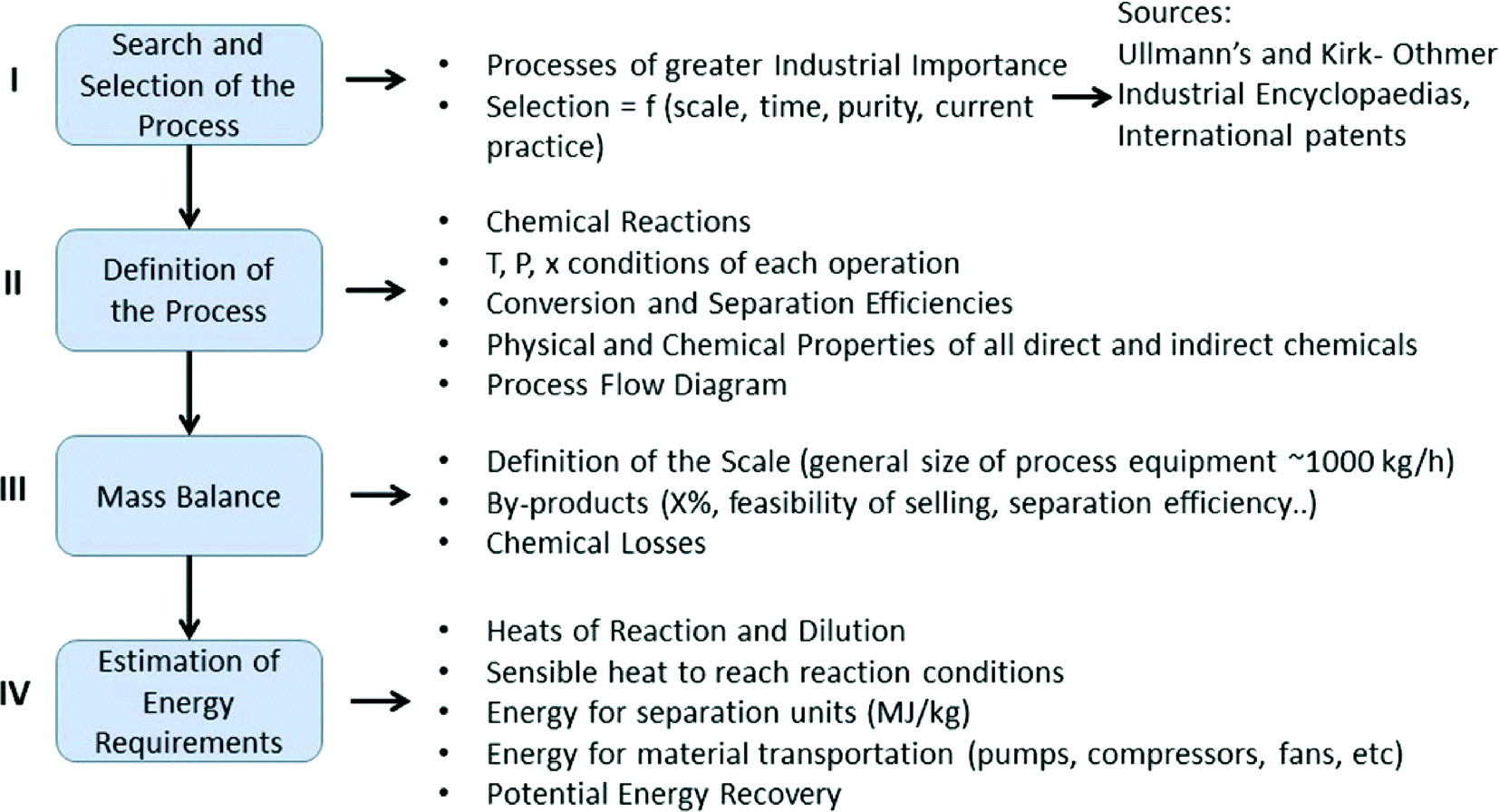 | ||
| Fig. 1 Development of LCIs for pharmaceutical API manufacture. | ||
The catalysts used in both batch and flow amination processes (Pd(OAc)2/BINAP and [Pd(cin)(IPr*)Cl]) are complex organic molecules, which can be obtained from basic chemicals via several synthetic routes. The most industrially relevant routes were identified, chemical trees were built, and step-by-step modelling of each step and of the overall synthesis were performed. Chemical trees to the catalysts are shown in the ESI,† Fig. S3. In the same way, LCIs of sodium tert-butoxide, potassium tert-amylate and N-methylpiperazine were built. The functional unit for this study was taken as 1 kg of the target product.
We did not build the LCI of the AstraZeneca aryl bromide substrate, since the functional unit of LCA analysis is the production of 1 kg of the target product, which requires a similar amount of substrate in both the batch and the flow processes. However, another reagent – N-methylpiperazine – had to be modelled, since the conditions of batch and flow processes with respect to the amount of N-methylpiperazine used differ significantly.
Thermodynamic properties of the chemicals needed during the modelling process for appropriate energy consumption calculations (heat capacities, latent heat, viscosity, density) were either taken from the literature,39 calculated by group-contribution methods,40 or modelled by properties prediction toolbox (ProPred) of ICAS (Integrated Computer Aided System, http://www.capec.kt.dtu.dk/Software/ICAS-and-its-Tools/ICAS-Toolboxes) and Gaussian 09 software. No hardware was included in the assessment.
Results and discussion
Experimental flow processes in a microreactor mini-plant and a meso-scale pilot plant
In order to compare the processes, we summarise the optimised reaction conditions and their results for the batch process using Pd(OAc)2/BINAP catalyst and NaOtBu base, a microreactor flow experiment using [Pd(IPr*)(cin)Cl] catalyst and KOtAm base and a pilot-scale flow experiment using the new catalytic system. The relevant results of batch and flow Buchwald–Hartwig aminations are shown in Table 1.| Process | Catalyst | Base, eq. | MP/ArBr, eq. | Res time, min | T, °C | X, % | Yield, % | Pd in product |
|---|---|---|---|---|---|---|---|---|
| Batch22 | Pd(OAc)2/BINAP | NaOtBu, 1.4 eq. | 2 | 240 | 100 | 100 | 95 | — |
| Flow, lab mini-plant | [Pd(IPr*)(cin)Cl] | KOtAm, 1.0 eq. | 1.15 | 10 | 70 | 100 | 99 | <1 ppm |
| Flow, pilot plant | [Pd(IPr*)(cin)Cl] | KOtAm, 1.5 eq. | 1.13 | 24 | 60–70 | 100 | 93 | <1 ppm |
The time to obtain 1 kg of product is 240 min under batch conditions and 825 min in the flow pilot plant. The reason for the significantly longer reaction time in the pilot flow reactor is the low concentrations of reactants used. The corresponding time to produce 1 kg in the lab-scale mini-plant is around 11000 min. However, these values must be re-calculated into space–time yields (STYs) to obtain the true measure of productivity of these three reactor systems. In the units of kg (product) h−1 L−1 (reactor volume) the STYs for these three reactor systems are 0.017, 0.546 and 0.145 for batch, lab scale mini-plant and pilot scale flow plant. The much higher STY of the mini-plant reflects the shortest used residence time at the highest used reactant concentrations, resulting in the highest production rate. The rates of heat and mass transfer are likely to be different between the three different reactor systems, but those are of little influence in this specific reaction due to low reaction rates and low heat effect. Thus, we attribute the higher productivity of the mini-plant to (a) higher concentrations of reactants and catalyst used, which reduced residence time and increased throughput and (b) possibly to better control of water concentration at the initial phase of the reaction. At the latter stage this makes no difference as the catalyst feed becomes wet, being mixed with the wet toluene–catalyst recycling feed.
The switch to a more active catalyst allows to reduce the reaction temperature from 100 to 60–70 °C. Another significant change in reaction conditions is the ratio of N-methylpiperazine to aryl bromide, which is changed to stoichiometric. In all demonstration experiments, quantitative or nearly quantitative conversion of aryl bromide was reached. For the demonstration runs, no blockage of the reactor with solids occurred. This was, in part, due to the lower concentration of the starting material and base used. For the flow mini-plant experiments, the yields were around 99% with no by-product detected. Palladium was either not detected in the product or the detected concentration was <1 ppm. This concentration of residual metal was one of the success criteria for developing the flow process. Turnover numbers calculated for batch and flow processes are 58.5 and 428, respectively, showing a significantly higher activity of the new catalyst.
As shown in the batch amination process,22 protodehalogenation leading to formation of the by-product shown in Scheme 2 is the main competing side-reaction, and a number of factors were found to influence its formation. In the optimised batch process, typical levels of this by-product were 1.8 to 6% with an extraction protocol employed to purge it prior to the following step. In all demonstration runs less than 1% of by-product was detected, which is a clear improvement over the batch process. No by-product was observed in the lab scale flow mini-plant experiments, indicating the benefit of continuous processing in improving reaction selectivity.
 | ||
| Scheme 2 Structure of the by-product obtained by protodehalogenation. | ||
When operating such complex reactions as Buchwald–Hartwig amination, there is little freedom of choice of the catalyst/base/solvent system. It becomes critically important to establish effective recycling of solvent and catalyst to reduce environmental impacts and improve process economics. In the optimised batch process, an excess of the starting reagent N-methylpiperazine is used and an undesired by-product is formed. Both factors make catalyst recycling more complex. The switch to an NHC-based catalyst, along with the use of continuous processing, allowed us to optimise the reaction system such that stoichiometric amounts of reagents could be used to obtain quantitative yield and effectively eliminate by-product formation.
To establish catalyst recycling, a work-up procedure was developed, which includes an aqueous acid wash, resulting in separation of catalyst into the organic phase and salted out product with the aqueous phase. An optimal and narrow range of pH values around 5.3 enables quantitative separation of the product. To test how this work-up procedure could be coupled with a flow process, we set-up the lab-scale mini-plant with catalyst workup and recycling.
Fig. 2 shows substrate conversion over time-on-stream with catalyst recycling. Reaction residence time is 10 min. Within the first 30 minutes, corresponding to three residence times, conversion remains at 100% and then gradually decreases to 60% in the next 10 minutes and to 30% after 50 minutes of the reaction. NMR analysis of the reaction sample did not show formation of a protodehalogenated by-product. The decrease in conversion is caused by the gradual accumulation of water (from phase separation) in the recycling system. Analysis of the aqueous product phase samples with ICP-OES did not show palladium contamination of the product.
 | ||
| Fig. 2 Continuous amination with catalyst work-up and recycle in a microreactor at 70 °C. | ||
An important parameter with respect to process economics is the product recovery ratio in the extraction. Based on the AstraZeneca experimental data, the workup was performed at pH of around 5.3. Under these conditions between 95% and 99% of the product was extracted into the aqueous phase, with the majority of samples indicating a recovery of more than 97%. In the laboratory mini-plant experiments neither aryl bromide nor the protodehalogenated by-product was found in any of the aqueous samples, being fully retained in the organic phase. The same holds true for the catalyst. Four samples were analysed by means of ICP. One sample had a Pd content of 1 ppm with the three other samples being below this value. At the pilot scale, product purity (93%) was slightly below the desired value of 95%.
Environmental and economic assessment
 | ||
| Fig. 3 Comparison of Recipe and CED scores for syntheses of Pd-BINAP and [Pd(IPr*)(cin)Cl] catalysts. | ||
| Abbreviation | Impact category | Units |
|---|---|---|
| GWP | Climate change | kg of CO2 – equivalents (eq.) per functional unit (FU) |
| FDP | Fossil fuel depletion potential | kg of oil per FU |
| HTP | Human toxicity potential | kg of 1,4-dichlorobenzene (1,4-DCB) – eq. per FU |
| MEP | Marine eutrophication potential | kg of nitrogen – eq. per FU |
| MDP | Metal depletion potential | kg of Fe – eq. per FU |
| NLTP | Natural land transformation potential | m2 per FU |
| ODP | Ozone depletion potential | kg of chlorofluorocarbon-11 per FU |
| POFP | Photochemical oxidant formation potential | kg of non-methane volatile organic compounds (MNVOC) – eq. per FU |
| TAP | Terrestrial acidification potential | kg of SO2 – eq. per FU |
| TETP | Terrestrial ecotoxicity potential | kg of 1,4-DCB – eq. per FU |
| CED | Cumulative energy demand | MJ per FU |
To understand the observed results, one should keep in mind that for many organic reactions the main contribution to environmental impact is the use of solvent. In the synthesis of Pd(OAc)2/BINAP catalyst, toluene is the main solvent. Hence, higher CED, FDP, POCP and TETP impact scores are observed. However, in the synthesis of [Pd(IPr*)(cin)Cl] catalyst, solvents such as methylene chloride and THF are involved, contributing to high scores in GWP, HTP, TAP and ODP impacts.
Detailed contributions of the various compounds and processes used in the Pd-NHC catalyst preparation to CED, GWP, HTP and TAP impacts are shown in Fig. 4. These environmental potentials are selected as important indicators of sustainability for the pharmaceutical industry. Human health was selected as the area of protection of highest priority and other impacts are contributing to the environmental pillar of sustainability.
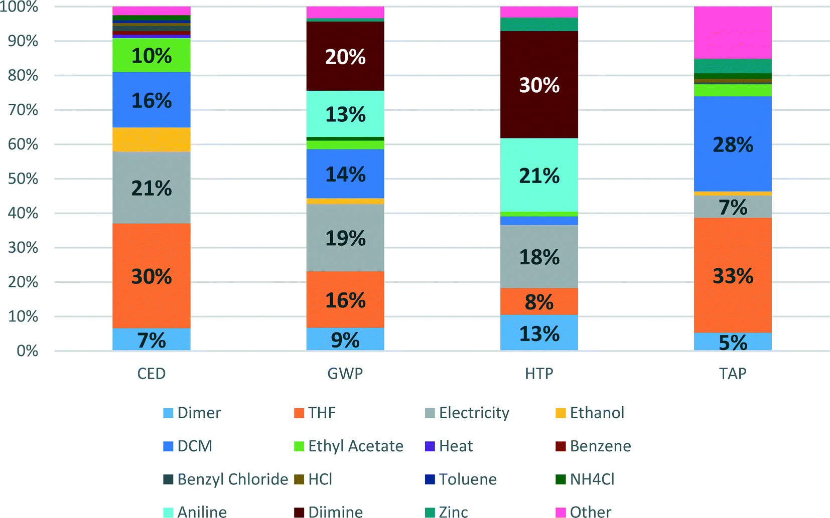 | ||
| Fig. 4 Detailed contributions to Recipe impacts of the synthesis of [Pd(IPr*)(cin)Cl] catalyst. | ||
CED represents the energy demand through the entire life cycle of a product. For the Pd-NHC catalyst production, the main contributions to energy consumption are due to production of solvents (THF (30%) and DCM (16%)), generation of electricity (21%) and production of ethyl acetate (10%). This indicator largely reflects contributions to another indicator – global warming potential (GWP), where apart from all contributions listed above (electricity – 19%, THF – 16%, DCM – 14%), significant inputs to energy demand are added on from production of aniline (13%) and diimine (20%) – synthetic catalyst preparation steps.
The shares of aniline and diimine production contributions to HTP become even higher – 21 and 30%, respectively, which is related to high HTP scores for use of hazardous solvents such as DCM and THF. The other significant contributors are electricity (18%), production of palladium dimer (13%) and actual production of THF (8%). For TAP, the main impact score contributors are again production of THF and DCM, showing 33 and 28%, respectively.
It should be noted that Pd(OAc)2/BINAP catalyst was modelled according to industrial production, whereas Pd-NHC catalyst for the flow process was synthesised within the SYNFLOW project in a lab, albeit at a 300 g scale. Its synthesis is not optimized for manufacture at an industrial scale. Hence, large amounts of solvents such as THF and DCM used within the synthesis may potentially be reduced following optimisation for manufacture. Thus, there is room for potential optimization of Pd-NHC catalyst synthesis, e.g., through recycle of solvents, and consequently for better environmental scores for this catalyst.
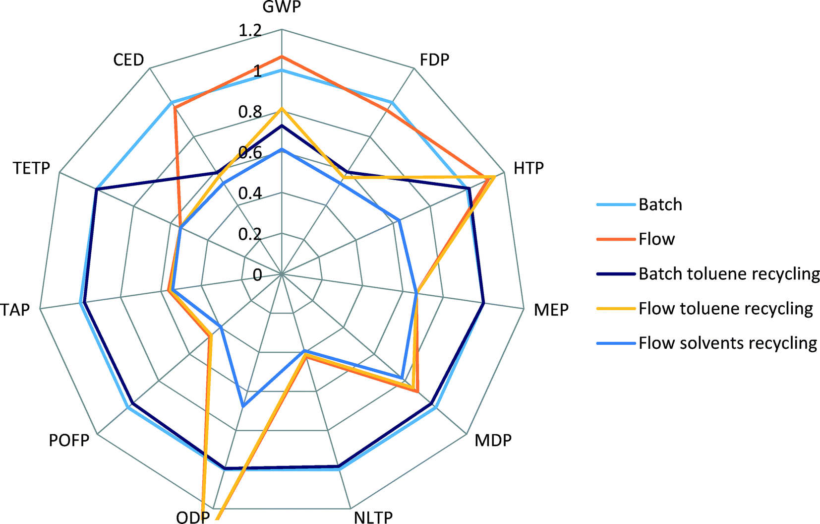 | ||
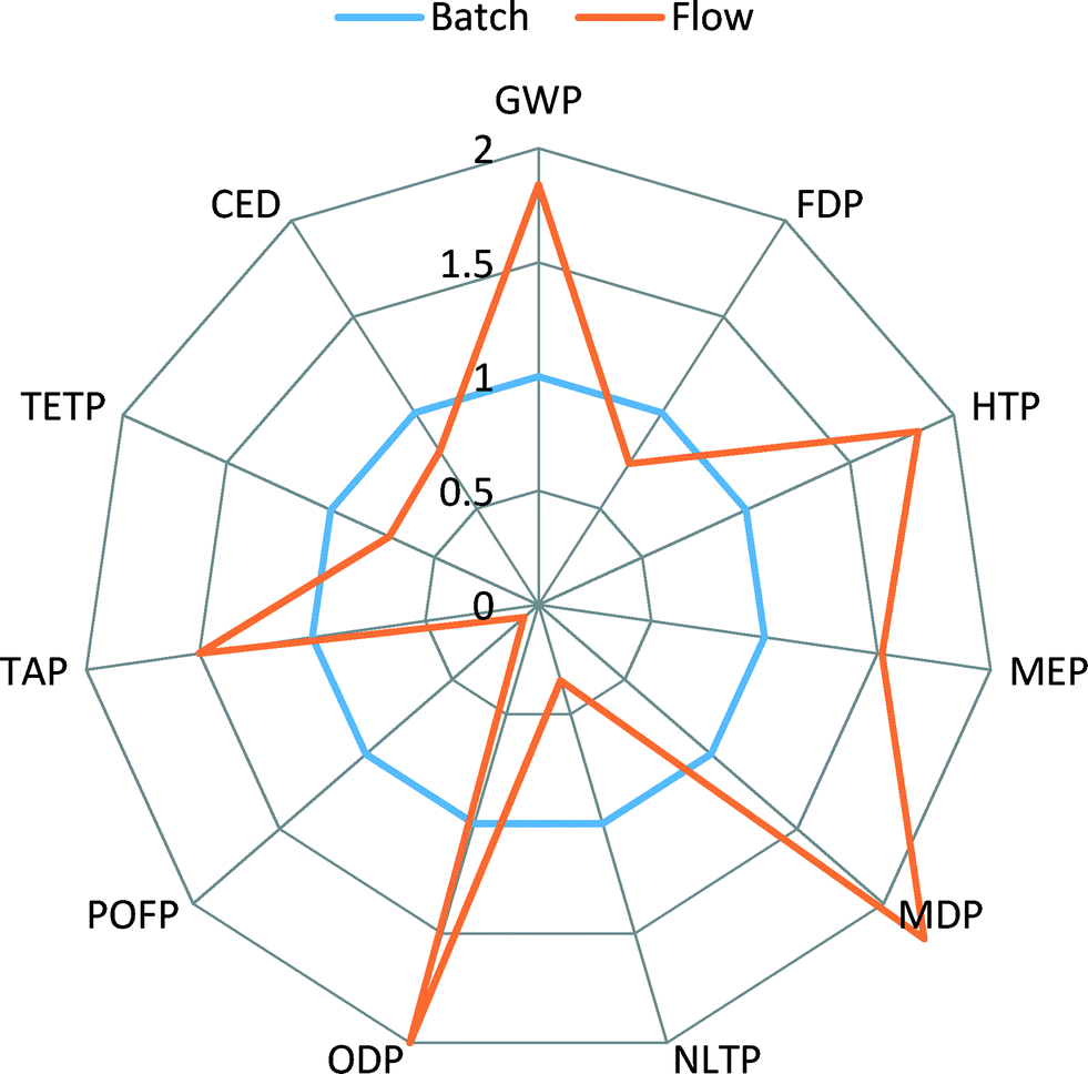
| Fig. 5 Comparison of Recipe 2008 midpoints and CED scores for different process scenarios. | ||
The batch scenario (results shown in blue colour) is taken as a basis for comparison, an internal benchmark, and all other scenarios are relative to it. It can be seen that the flow process (orange) shows higher scores for GWP, HTP and ODP, comparable scores for CED and FDP, and lower scores for all other indicators.
When toluene recycling is considered (grey for batch, yellow for flow), it becomes apparent which indicator scores are constituents of toluene production: an improvement in GWP, CED and FDP indicators is obtained. The scenario of a flow process with recycling of all solvents results in the lowest environmental scores across all the selected indicators, confirming that the use of solvents creates the highest potential for environmental burdens.
Indicators such as TAP, MEP, MDP and POFP show lower scores for the flow process, see Fig. 5, and do not change their values significantly when recycling of solvents is considered. Also, in comparison to production of Pd(OAc)2/BINAP and [Pd(IPr*)(cin)Cl] catalysts, see Fig. 3, these scores were higher for the new catalyst. This can be explained by the fact that the use of reactant N-methylpiperazine largely drives the values of these indicators in the flow process. Therefore, a decrease in the amount of N-methylpiperazine from two equivalents in the batch process to stoichiometric in the flow process significantly reduces the contributions of the overall process to several environmental indicators, outweighing the increased contributions from the new catalyst.
We specifically considered the contribution of toluene recycling to several selected indicators in both the batch and flow process scenarios. Results are shown in Fig. 6. This comparison makes clear the origin of the main impact contributors to the selected indicators. Production of toluene makes up to 58% and 38% of CED and GWP indicator scores for the flow process, while for the batch process those values are 41% and 30% for CED and GWP, respectively, as less solvent is used in the batch process. The share of N-methylpiperazine in the scores of CED, GWP and TAP indicators for the batch process is higher than for the flow process: 34 vs. 18%, 30 vs. 15% and 94 vs. 90%, respectively, as a larger amount is used in the batch process.
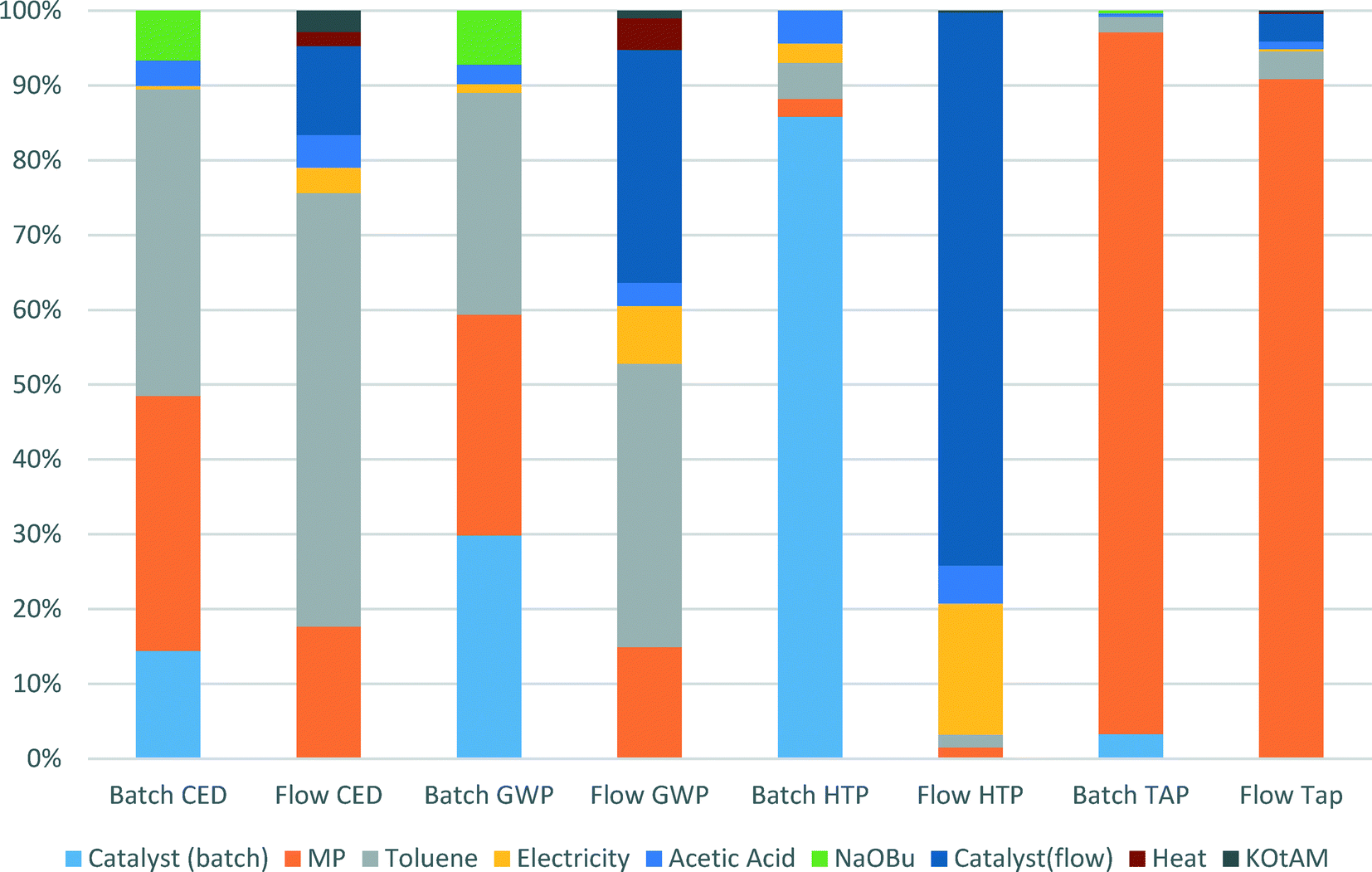 | ||
| Fig. 6 Contributions of catalyst manufacture, solvent recycling, base and energy inputs to selected indicators in the batch and the flow processes. | ||
For both the batch and the flow processes, impacts from the catalysts production are very significant and cannot be ignored. Thus, in the batch process 14% of CED score, 30% of GWP score and 86% of HTP score are due to catalyst production, whereas for the flow process the values of catalyst production share for the same indicators are 12, 31 and 74%, respectively.
Using an internally-developed cost of goods (CoG) tool (AstraZeneca internal tool based on a 15 kg batch), the pilot scale run of the Buchwald–Hartwig reaction was estimated to be ~9% more expensive per kilo than the original batch process. It is interesting to note that although the catalyst cost is higher for the pilot process (due to higher estimated bulk cost and higher loading), it is in fact the much higher dilution and the resulting process mass intensity (PMI) (15.4 versus 11.7 kg kg−1) that is the major cost contributor to this process. Conversely, the mini-plant process, run at a significantly lower dilution, gave an ~8% decrease in the overall cost of goods and a more favourable PMI of 10.8 kg kg−1.
This specific amination reaction is just one step in a multi-step reaction sequence to produce an API. The goal of the project was to overcome challenges of transferring C–N coupling reactions into flow processes, in order to enable translation of the entire API production into flow. The fact that environmental impacts of the new flow process are similar or better than those in the standard batch process, and the economics of the flow process are also better, is highly encouraging for potential future commercialisation of such processes.
Conclusions
In this paper, we developed a flow mini-plant using a conventional coiled tube reactor and a system for aqueous work-up and catalyst recycle. This mini-plant enabled us to validate the catalyst recycling strategy for the new process of C–N coupling in flow using a Pd-NHC catalyst. The mini-plant data were critical to establish the required amount of catalyst for the life cycle assessment study.A cradle-to-gate life cycle assessment was carried out in order to compare the developed flow process with the established industrial batch process. It has been shown that under the more concentrated conditions of the flow mini-plant, the use of the Pd-NHC catalyst can result in a significantly cheaper process and lower PMI than the Pd(OAc)2/BINAP catalyst used in the literature batch process. However, due to the more complex synthetic route, some of the environmental impacts of the Pd-NHC catalyst production are higher, showing particularly bad scores for climate change, human toxicity, and marine and freshwater ecotoxicity. Despite this, the overall flow process with catalyst recycling has lower or comparable environmental impact scores for almost all impact categories.
This LCA study is the first comprehensive analysis of the synthesis of complex molecularly defined catalysts. It has shown that the contribution of catalyst synthesis to the overall environmental impacts of the processes could be significant, when catalyst lifetime is relatively short. This study also emphasised again the significant role of solvents in environmental impacts of complex organic syntheses.
Acknowledgements
The research leading to these results has received funding from the European Research Council under the European Union's Seventh Framework Programme (EC FP7) Grant Agreement no. [NMP2-SL-2012-280827]. We acknowledge the help of Mr Vinzent Strobel (RWTH Aachen) with calculations using ICAS.References
- R. A. Sheldon, C. R. Acad. Sci., Ser. IIc: Chim., 2000, 3, 541–551 CrossRef CAS.
- P. T. Anastas and J. C. Warner, Green Chemistry: Theory and Practice, Oxford University Press, 1998 Search PubMed.
- P. T. Anastas and M. M. Kirchhoff, Acc. Chem. Res., 2002, 35, 686–694 CrossRef CAS PubMed.
- P. Anastas and J. Zimmermann, Environ. Sci. Technol., 2003, 37, 94A–101A CrossRef PubMed.
- D. J. C. Constable, P. J. Dunn, J. D. Hayler, G. R. Humphrey, J. J. L. Leazer, R. J. Linderman, K. Lorenz, J. Manley, B. A. Pearlman, A. Wells, A. Zaks and T. Y. Zhang, Green Chem., 2007, 9, 411–420 RSC.
- V. Hessel, B. Cortese and D. M. H. J. M. Croon, Chem. Eng. Sci., 2011, 66, 1426–1448 CrossRef CAS.
- D. Gutmann, D. Cantillo and C. O. Kappe, Angew. Chem., Int. Ed., 2015, 54, 6688–6728 CrossRef PubMed.
- D. M. Roberge, B. Zimmermann, F. Rainone, M. Gottsponer, M. Eyholzer and N. Kockmann, Org. Process Res. Dev., 2008, 12, 905–910 CrossRef CAS.
- C. Jimenez-Gonzalez, P. Poechlauer, Q. B. Broxterman, B. S. Yang, D. A. Ende, J. Baird, C. Bertsch, R. E. Hannah, P. Dell'Orco, H. Noorrnan, S. Yee, R. Reintjens, A. Wells, V. Massonneau and J. Manley, Org. Process Res. Dev., 2011, 15, 900–911 CrossRef CAS.
- U. Hintermair, G. Francio and W. Leitner, Chem. Commun., 2011, 47, 3691–3701 RSC.
- A. Lapkin, A. Voutchkova and P. Anastas, Chem. Eng. Process., 2011, 50, 1027–1034 CrossRef CAS.
- D. S. Surry and S. L. Buchwald, Angew. Chem., Int. Ed., 2008, 47, 6338–6361 CrossRef CAS PubMed.
- C. Torborg and M. Beller, Adv. Synth. Catal., 2009, 351, 3027–3043 CrossRef CAS.
- I. P. Beletskaya and A. V. Cheprakov, Organometallics, 2012, 31, 7753–7808 CrossRef CAS.
- C. Mauger, O. Buisine, S. Caravieilhes and G. Mignani, J. Organomet. Chem., 2005, 690, 3627–3629 CrossRef CAS.
- T. Noel, J. R. Naber, R. L. Hartman, J. P. McMullen, K. F. Jensen and S. L. Buchwald, Chem. Sci., 2011, 2, 287 RSC.
- T. Noël and S. L. Buchwald, Chem. Soc. Rev., 2011, 40, 5010–5029 RSC.
- G. Bastug and S. P. Nolan, Organometallics, 2014, 33, 1253–1258 CrossRef CAS.
- G. C. Fortman and S. P. Nolan, Chem. Soc. Rev., 2011, 40, 5151–5169 RSC.
- A. Pommella, G. Tomaiuolo, A. Chartoire, S. Caserta, G. Toscano, S. P. Nolan and S. Guido, Chem. Eng. J., 2013, 223, 578–583 CrossRef CAS.
- R. K. Henderson, C. Jimenez-Gonzalez, D. J. C. Constable, S. R. Alston, G. G. A. Inglis, G. Fisher, J. Sherwood, S. P. Binks and A. D. Curzons, Green Chem., 2011, 13, 854–862 RSC.
- H.-J. Federsel, M. Hedberg, F. R. Qvarnström and W. Tian, Org. Process Res. Dev., 2008, 12, 512–521 CrossRef CAS.
- N. Marion, O. Navarro, J. Mei, E. D. Stevens, N. M. Scott and S. P. Nolan, J. Am. Chem. Soc., 2006, 128, 4101–4111 CrossRef CAS PubMed.
- A. Perazzo, G. Tomaiuolo, L. Sicignano, G. Toscano, R. E. Meadows, S. P. Nolan and S. Guido, RSC Adv., 2015, 5, 63786–63792 RSC.
- D. Cespi, F. Passarini, G. Mastragostino, I. Vassura, S. Larocca, A. Iaconi, A. Chieregato, J. L. Dubois and F. Cavani, Green Chem., 2015, 17, 343–355 RSC.
- P. Yaseneva, C. F. Marti, E. Palomares, X. Fan, T. Morgan, P. S. Perez, M. Ronning, F. Huang, T. Yuranova, L. Kiwi-Minsker, S. Derrouiche and A. A. Lapkin, Chem. Eng. J., 2014, 248, 230–241 CrossRef CAS.
- D. Gericke, D. Ott, V. G. Matveeva, E. Sulman, A. Aho, D. Y. Murzin, S. Roggan, L. Danilova, V. Hessel, P. Loeb and D. Kralisch, RSC Adv., 2015, 5, 15898–15908 RSC.
- O. G. Griffiths, R. E. Owen, J. P. O'Byrne, D. Mattia, M. D. Jones and M. C. McManus, RSC Adv., 2013, 3, 12244–12254 RSC.
- D. Ott, D. Kralisch, I. Denčić, V. Hessel, Y. Laribi, P. D. Perrichon, C. Berguerand, L. Kiwi-Minsker and P. Loeb, ChemSusChem, 2014, 7, 3521–3533 CrossRef CAS PubMed.
- D. Cespi, E. S. Beach, T. E. Swarr, F. Passarini, I. Vassura, P. J. Dunn and P. T. Anastas, Green Chem., 2015, 17, 3390–3400 RSC.
- W. De Soete, S. Debaveye, S. De Meester, G. Van der Vorst, W. Aelterman, B. Heirman, P. Cappuyns and J. Dewulf, Environ. Sci. Technol., 2014, 48, 12247–12255 CrossRef CAS PubMed.
- C. Jimenez-Gonzalez and M. R. Overcash, Green Chem., 2014, 16, 3392–3400 RSC.
- A. P. Markusse, B. F. M. Kuster, D. C. Koningsberger and G. B. Marin, Catal. Lett., 1998, 55, 141–145 CrossRef CAS.
- R. H. M. Goedkoop, M. Huijbregts, A. D. Schryver, J. Struijs and R. V. Zelm, Recipe 2008 - A Life Cycle Assessment Method which Comprises Harmonised Category Indicators at Midpoint and the Endpoint Level, The Hague, 2009 Search PubMed.
- R. Frischknecht, R. Heijungs and P. Hofstetter, Int. J. Life Cycle Assess., 1998, 3, 266–272 CrossRef CAS.
- M. A. J. Huijbregts, S. Hellweg, R. Frischknecht, H. W. M. Hendriks, K. Hungerbühler and A. J. Hendriks, Environ. Sci. Technol., 2010, 44, 2189–2196 CrossRef CAS PubMed.
- http://www.environmentalclarity.com .
- http://www.ecoinvent.org .
- Lange's Handbook of Chemistry, ed. J. A. Dean, McGraw-Hill, Inc., 15th edn, 1999 Search PubMed.
- R. C. Reid, The properties of gases and liquids, McGraw-Hill, Inc., 4th edn, 1987 Search PubMed.
- C. Capello, S. Hellweg and K. Hungerbühler, J. Ind. Ecol., 2008, 12, 111–127 CrossRef.
Footnote |
| † Electronic supplementary information (ESI) available. See DOI: 10.1039/c5re00048c |
| This journal is © The Royal Society of Chemistry 2016 |