
 Open Access Article
 This Open Access Article is licensed under a Creative Commons Attribution-Non Commercial 3.0 Unported Licence
The non-planarity of the benzene molecule in the X-ray structure of the chelated bismuth(III) heteroboroxine complex is not supported by quantum mechanical calculations†
Jindřich
Fanfrlík
a,
Robert
Sedlak
a,
Adam
Pecina
a,
Lubomír
Rulíšek
a,
Libor
Dostál
b,
Ján
Moncóľ
c,
Aleš
Růžička
*b and
Pavel
Hobza
*ad
aInstitute of Organic Chemistry and Biochemistry, Academy of Sciences of the Czech Republic, 166 10 Prague 6, Czech Republic. E-mail: hobza@uochb.cas.cz
bDepartment of General and Inorganic Chemistry, Faculty of Chemical Technology, University of Pardubice, Studentská 573, CZ-532 10, Pardubice, Czech Republic. E-mail: ales.ruzicka@upce.cz
cInstitute of Inorganic Chemistry, Faculty of Chemical and Food Technology, Slovak University of Technology, Slovak University of Technology, SK-812 37 Bratislava, Slovakia
dRegional Centre of Advanced Technologies and Materials, Department of Physical Chemistry, Palacký University, 771 46 Olomouc, Czech Republic
First published on 6th November 2015
Abstract
The non-planarity of the benzene moiety in the crystal of a chelated bismuth(III) heteroboroxine complex was not supported by DFT-D quantum chemical calculations. The observed bent structure of benzene is in fact a superimposition (thermal average) of the ensemble of thermally populated benzene structures in the complex studied.
The X-ray crystallography is probably the single most important experimental technique determining the three-dimensional structures of solid-state materials. It provides a unique insight into the structure of molecular crystals, including the mutual arrangement of the entities involved and their various conformations, and it often makes it possible to deduce essential contributions to the reactivity of small molecules. On the other hand, owing to the routine character of data processing and structural refinement, often carried out by employing (semi)automatic programs1 and software, there is some tendency to overlook subtle structural details, which may indicate new and important phenomena. A specific example of the “failure” is statically disordered structures where a particular electron density can be attributed or split into two (or rarely even more) parts of the molecule. The use of the recommended splitting procedures2 implemented in modern crystallographic software packages can sometimes even omit a chemically interesting position of an atom or a distortion of the molecule, such as a conformation corresponding to the structure of a possible intermediate/transition state or a product of a weak interaction with molecules in close vicinity.
Although adducts of the lower valence group 15 metal halides and π-systems are well established as Menshutkin complexes,3 there is only a limited number of coordination or organometallic compounds4 where this type of non-covalent interaction is not accompanied and supported by further interactions from ligands. For the heaviest element in group 15 – bismuth, the vast majority of these unsupported adducts can be described as complexes of binary bismuth(III) halides or various clusters with simple aromatic molecules such as benzene or its substituted derivatives,5 with some of those being in their crystal structures statically disordered.6 In the case of a recently reported synthesis of a chelated bismuth(III) heteroboroxine complex,7 the benzene molecule was found within the unit cell having a short contact with the Bi atom (Fig. 1 – left). The Bi⋯π interactions have been extensively studied both experimentally8 and theoretically.9 The positively charged σ-hole10 at the Bi atom might also play an important role in the interactions with the negatively charged π-electrons of the benzene moiety. At the same time, it appears that the non-planar benzene molecule (Fig. 1 – right) is disordered. The disorder originates in the distortion of one of the carbon atoms in the direction highlighted by the red arrow in Fig. 1 – left. Various crystallographic procedures tend to split the electron density and model this disorder to make the ring planar.
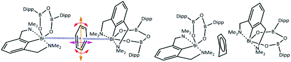 | ||
| Fig. 1 Organobismuth heteroboroxine–benzene complex under investigation; Dipp is 2,6-(diisopropyl)phenyl; left—possible ways of pendulation, oscillation and rotation of the benzene molecule between two Bi atoms, right—schematic representation of the primary crystallographic result. | ||
However, a careful inspection of the unit cell reveals that the benzene molecule under investigation has another type of weak contact with the Bi atom from the neighboring molecule (highlighted by the blue lines in Fig. 1 – left). The question arises whether this is a cumulative effect of all of these close contacts/interactions that is responsible for the non-planar structure of the benzene molecule as shown in Fig. 1 – right, Fig. S4 and S5 (ESI†) or its non-planarity is an artefact of the crystallographic procedures. When the structure is solved and refinement was performed with another software (SHELXT, SHELXL-2014/7, WinGX-2014.1, SQUEEZE) the positional disorder of one bismuth atom and the ligand together with a rotation of the benzene around its centroid is observed (Fig. S6 and S7 (ESI)†). To answer this question, we have decided to investigate the complex shown in Fig. 1 by using quantum mechanical (QM) techniques. These supposedly provide a reliable description of various types of noncovalent interactions acting within the complex molecular structure under investigation. It can be anticipated that its equilibrium geometry is determined by a genuine interplay between the electrostatic, induction, charge-transfer, dispersion and exchange–repulsion interactions. Specifically, we have used the DFT method with empirical dispersion (D3)11 combined with the TPSS functional and TZVPP bases set, and DFT-SAPT methods12 (more details in the ESI†). The former method makes it possible to compute the total energy and thus also interaction energy for the whole complex (over 250 atoms) while the latter scheme (DFT-SAPT) provides the decomposition of interaction energy into different components (interaction terms). Since DFT-SAPT calculations are computationally intensive and thus impractical for the whole complex, they were performed for only two smaller parts containing benzene with one Bi-containing molecule.
The initial task of our computational investigation consists of the evaluation of the deformation energy accompanying the planarization/deplanarization of the benzene molecule. To this aim, the nonplanar geometry of the benzene molecule in the reported crystal structure was relaxed, i.e. the positions of all the benzene atoms were optimized (DFT-D3/TPSS/TZVPP) while all the other heavy atoms of the complex were kept frozen. As expected, the resulting fully planar structure is energetically more favorable than the structure with non-planar benzene rings (i.e. the structure where only H atoms have been optimized) by 7.2 kcal mol−1. Similar deplanarization energies were obtained by using the B-P86, PBE and B97D functionals (7.3, 7.1 and 7.3 kcal mol−1, respectively). Such energies are not available under the conditions of the experiment (six measurements of three different crystals from different crystallization crops at temperatures of 100–200 K); therefore, the nonplanar structure cannot be populated. Geometry optimization has confirmed that neither the σ complex nor a Wheland intermediate13 (where the nonplanar carbon in sp3 hybridization is bound to two carbons, one hydrogen and one Bi atom) is formed. This is caused by the fact that the Bi atom is located more above the benzene ring than close to some carbon atoms of the benzene ring (with the shortest distance between Bi and the distorted C atom of the benzene being about 4.2 Å).
Alternatively, the bending of benzene could also be explained by its partial hydrogenation or large and asymmetric polarization of the benzene molecule by the two Bi atoms.
The optimized structure of the protonated benzene (C6H7+) is, however, practically planar (not shown). In addition, the positive charge on the benzene ring would have to be compensated for by the negative charge. However, the presence of an anion has not been observed in the crystal structure reported. Apart from the protonated benzene, we have also considered a neutral dihydrogenated benzene molecule (cyclohexa-1,3-diene). Its optimized structure (not shown) has a bent conformation with a single C–C bond. The single C–C bond is about 0.2 Å longer than the other C–C bonds. Such a structure is, however, incompatible with the crystal one.
The asymmetric polarization of the benzene molecule is another, rather a plausible explanation of the nonplanarity of the benzene moiety. In order to prove it, we have calculated the electron difference map. Fig. 2 and S2 (ESI†) show these maps for the binary Bi(1)⋯benzene complex (A), the binary benzene⋯Bi(2) complex (B) and the tertiary Bi(1)⋯benzene⋯Bi(2) adduct (Fig. 2). The difference maps of both the adducts (Fig. S2A and S2B (ESI)†) show some small electron redistribution in the intermolecular region upon complex formation. However, in the case of the tertiary adduct (Fig. 2), the electron redistribution is considerably smaller. Evidently, this is a consequence of the mutual compensation of electron densities from both Bi-containing molecules. It is evident from the figure that no significant electron redistribution takes place upon whole complex formation.
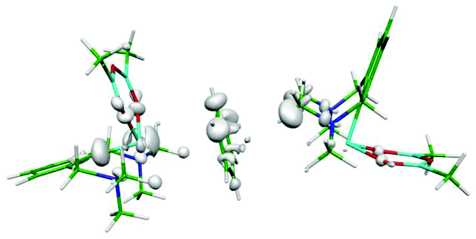 | ||
| Fig. 2 Electron differential map of the Bi⋯benzene⋯Bi complex. The 0.00033 a.u. isodensity surface is depicted. | ||
Finally, a careful inspection of the spatial arrangement of the benzene moiety between two Bi atoms has revealed that the volume of the cavity is large enough to allow the benzene to undergo rather large motions in it. To confirm this hypothesis, we investigated the potential energy surface (PES) of the benzene molecule within the complex using a relaxed scan. The benzene molecule was moving between the two Bi atoms in two ways: (A) the center of mass of benzene was constrained; (B) only the single C atom was constrained. The positions of all the other atoms of the benzene molecule were optimized, whereas the remaining heavy atoms of the complex were kept frozen. Fig. S3† demonstrates that the PESs of the benzene movement were very flat, which illustrates motion B (red points) even better. The figure shows an extended part of the PES (−0.1 – 0.1 Å and −0.2 – 0.3 Å, for curves A and B, respectively) below 0.3 kcal mol−1 (approximately the energy of the thermal motion at 150 K). This means that the benzene moiety has a reasonably large space available for thermal motion (∼0.5 Å for B; not only between two Bi atoms but also perpendicular to it). Fig. 3 visualizes the relevant benzene structures for both types of motion and the black benzene ring represents the crystal conformation of benzene. Obviously, the experimentally found bent structure of benzene is fully superimposed by the set of thermally populated benzene structures.
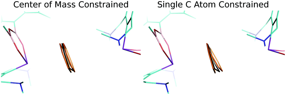 | ||
| Fig. 3 Positions of the benzene molecule obtained by the relaxed scan. Color code: orange – position of the benzene molecule with the relative energy of about 0.3 kcal mol−1 obtained by the relaxed scan; black – the X-ray structure position of the benzene molecule. | ||
The flatness of the PES is a very important property of the studied system. It originates from the position of the benzene moiety moving between two Bi atoms. The asymmetry of the PES around the crystal position (cf. Fig. S3†) arises from the asymmetry of two Bi-containing subsystems. Fig. 4 shows the electrostatic potential (ESP) for the Bi(1)⋯benzene (A) and Bi(2)⋯benzene (B) parts of the whole complex (cf. Fig. 1). It is evident that the area with the most positive ESP (i.e. the σ-hole, Vs,max = 27.3 kcal mol−1) is hidden behind the NMe2 moieties. The ESP value of the NMe2 moieties is comparable to the ESP of the Bi atom (Vs,max = 23.5 kcal mol−1). The Bi atom is thus not directly accessible for benzene in this complex. This interaction can thus be classified as a mixture of C–H⋯π interactions and weak σ-hole bonding (pnicogen or pnictogen bonding).14 The potential energy curve for the Bi(2) (Fig. 4A) shows that the equilibrium distance between the center of mass of the benzene molecule and the Bi atoms is about 5 Å. The benzene molecule cannot move closer due to the steric clashes with the NMe2 moieties; the respective stabilization energy is only about 4.4 kcal mol−1. Moreover, the calculation of stabilization energies on fragmented complexes confirmed the importance of C–H⋯π interactions. The sum of the interaction energies between the benzene and trimethylamine moieties makes about 55% of the total stabilization energy (2.4 out of 4.4 kcal mol−1). The interaction is thus stronger in the Bi(1)⋯benzene complex (Fig. 4B), where the benzene interacts with the less positive (Vs,max = 8.3 kcal mol−1) but more easily accessible part of the Bi atom. Here, the equilibrium distance is shorter (about 3.6 Å, which is less than the sum of vdW radii) the σ-hole bonding stronger and the stabilization energy is larger, about 8.9 kcal mol−1. The relative importance of C–H⋯π interactions is considerably smaller in this case. The sum of the interaction energies between the benzene and trimethylamine moieties makes only about 25% of the total stabilization energy here (2.2 out of 8.9 kcal mol−1). The σ-hole bonding thus plays the dominant role in the studied complex. This interaction can be characterized as a medium–strong σ-hole bond and is comparable to calculated interaction energy for the BiX3⋯C6H6 2![[thin space (1/6-em)]](https://www.rsc.org/images/entities/char_2009.gif) :1 adduct (X3-is an amine-tris(phenoxide))5e being 5.2 kcal mol−1. The crystal position of the benzene molecule is again at the minimum of the potential energy curve. The stabilization energies have been decomposed using the DFT-SAPT method (see Table 1). The computed data show that the interactions of both complexes are of similar nature with most important dispersion energies followed by electrostatic and induction energies. Higher stability of the Bi(1)⋯benzene complex (by 3.9 kcal mol−1) is clearly due to more attractive electrostatic, dispersion and induction terms (2.0 + 2.0 + 1.7 kcal mol−1) which are not compensated by only a repulsive exchange–repulsion term (1.8 kcal mol−1).
:1 adduct (X3-is an amine-tris(phenoxide))5e being 5.2 kcal mol−1. The crystal position of the benzene molecule is again at the minimum of the potential energy curve. The stabilization energies have been decomposed using the DFT-SAPT method (see Table 1). The computed data show that the interactions of both complexes are of similar nature with most important dispersion energies followed by electrostatic and induction energies. Higher stability of the Bi(1)⋯benzene complex (by 3.9 kcal mol−1) is clearly due to more attractive electrostatic, dispersion and induction terms (2.0 + 2.0 + 1.7 kcal mol−1) which are not compensated by only a repulsive exchange–repulsion term (1.8 kcal mol−1).
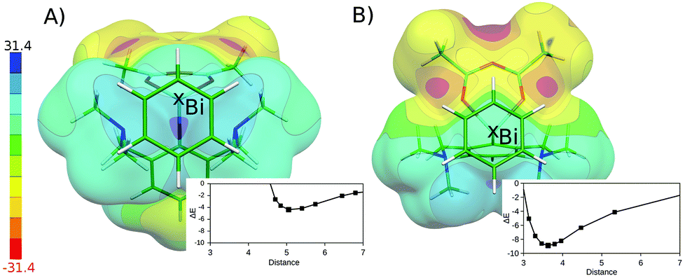 | ||
| Fig. 4 ESP of the isolated chelated bismuth(III) heteroboroxine complex. For clarity, the position of the partner benzene molecule is depicted. The Bi⋯benzene dissociation curves are plotted. The interaction energy (ΔE) in kcal mol−1; the distance between the Bi atom and the center of mass of benzene molecule in Å. The (A) Bi(2)⋯benzene and (B) Bi(1)⋯benzene distances. | ||
| Dimer | E 1 Pol | E 1 Ex | E D | E 2 Ex-Ind + E2Ind + δHF | ΔE |
|---|---|---|---|---|---|
| Bi(1)⋯benzene | −4.9 | 7.9 | −8.0 | −2.6 | −7.6 |
| Bi(2)⋯benzene | −2.9 | 6.1 | −6.0 | −0.9 | −3.7 |
Although there is a plethora of procedures for crystal structure prediction and calculation based on ab initio methods or cooperation of X-ray, NMR and theoretical methods is reported15 but to the best of our knowledge only one paper deals with a post-treatment of disordered small molecules.16 An interesting observation was made when the positions of the carbon atoms obtained by theoretical calculations (a scan variant with a single C atom constrained) were fitted into the crystallographic positions. Specifically, the “theoretical” coordinates of all atoms were refined freely by the SHELXL 2013 program against the reflection file, which led to a new set of positions of the carbon atoms. It is clear that the refinement of the primary-disorder carbon atom resulting in a single planar benzene ring would be wrong because of the omissions of several (according to X-ray data quality and the resolution of the Fourier electron density map) positions of the benzene molecule which pendulates (one carbon atom is rigid and the rest of the electron density attributable to the carbon atoms migrates horizontally), oscillates (in a slight vertical motion) and rotates (around C6 axis) between the two bismuth atoms. This is probably caused by the fact that the only rigid carbon atom of the benzene molecule is found in the special crystallographic position; moreover, it is influenced by two types of interactions with both Bi atoms, which pull the electron density of the ring into different directions.
It may be concluded that the QM calculations of the studied intermolecular complexes clearly demonstrate an almost free motion of the benzene molecule between the two Bi atoms, and the bent structure of benzene obtained by X-ray crystallography is in fact a superimposition (thermal average) of the ensemble of thermally populated benzene structures in the complex studied. The motion is enabled by the relatively large volume available around the benzene molecule and by its spatial orientation, allowing for the formation of two competing asymmetric Bi(σ- hole)⋯π bonds.
This work was a part of the Research Project RVO: 61388963 of the Institute of Organic Chemistry and Biochemistry, Academy of Sciences of the Czech Republic. This work was also supported by the Czech Science Foundation [P208/12/G016, P207/13-00289S and 14-31419S] and the operational program Research and Development for Innovations of the European Social Fund (CZ 1.05/2.1.00/03/0058).
Notes and references
- (a) G. M. Sheldrick, Acta Crystallogr., Sect. A: Fundam. Crystallogr., 2008, 64, 112 CrossRef CAS PubMed; (b) O. V. Dolomanov, L. J. Bourhis, R. J. Gildea, J. A. K. Howard and H. Puschmann, J. Appl. Crystallogr., 2009, 42, 339 CrossRef CAS.
- (a) Crystal Structure Refinement, in A Crystallographer's Guide to SHELXL, ed. P. Müller, IUCr, Oxford University Press Inc., New York, 2006 Search PubMed; (b) S. W. Ng, Chin. J. Struct. Chem., 2005, 24, 1425 CAS; (c) P. V. Solntsev, Tutorial, disorder refinement using Crystals software, 2013, http://www.xtl.ox.ac.uk/wp-content/uploads/2013/04/crystals_disorder_manual-2013-04-09.pdf; (d) D. Kratzert, J. J. Holstein and I. Krossing, J. Appl. Crystallogr., 2015, 48, 933 CAS.
- H. Schmidbaur and A. Schier, Organometallics, 2008, 27, 2361 CrossRef CAS.
- For example see: (a) S. Shimada, O. Yamazaki, T. Tanaka, Y. Suzuki and M. Tanaka, J. Organomet. Chem., 2004, 689, 3012 CrossRef CAS; (b) S. L. Benjamin, L. Karagiannidis, W. Levason, G. Reid and M. C. Rogers, Organometallics, 2011, 30, 895 CrossRef CAS; (c) X. Zhang, R. Qiu, N. Tan, S. Yin, J. Xia, S. Luo and C.-T. Au, Tetrahedron Lett., 2010, 51, 153 CrossRef CAS; (d) X. Kou, X. Wang, D. Mendoza-Espinosa, L. N. Zakharov, A. L. Rheingold, W. H. Watson, K. A. Brien, L. K. Jayarathna and T. A. Hanna, Inorg. Chem., 2009, 48, 11002 CrossRef CAS PubMed.
- (a) M. Mehring and M. Schürmann, Chem. Commun., 2001, 2354 RSC; (b) A. Schier, J. M. Wallis, G. Muller and H. Schmidbaur, Angew. Chem., Int. Ed. Engl., 1986, 25, 757 CrossRef; (c) P. C. Andrews, P. C. Junk, I. Nuzhnaya and L. Spiccia, Dalton Trans., 2008, 2557 RSC; (d) L. E. Turner, M. G. Davidson, M. D. Jones, V. S. Schulz and P. J. Wilson, Inorg. Chem., 2006, 45, 6123 CrossRef CAS PubMed; (e) K. Yu. Monakhov, C. Gourlaouen, T. Zessin and G. Linti, Inorg. Chem., 2013, 52, 6782 CrossRef CAS PubMed.
- (a) D. Mansfeld, M. Mehring and M. Schürmann, Angew. Chem., Int. Ed., 2005, 44, 245 CrossRef CAS PubMed; (b) A. M. Arif, A. H. Cowley, N. C. Norman and M. Pakulski, Inorg. Chem., 1986, 25, 4836 CrossRef CAS.
- Reported synthesis of chelated bismuth(III) heteroboroxine complex: M. Kořenková, M. Erben, R. Jambor, A. Růžička and L. Dostál, J. Organomet. Chem., 2014, 772–773, 287 CrossRef ; in its structure the electron density of benzene molecule has been omitted and the cavity modeled by SQUEEZE program.
- (a) M. M. Watt, M. S. Collins and D. W. Johnson, Acc. Chem. Res., 2013, 46, 955 CrossRef CAS PubMed; (b) V. M. Cangelosi, L. N. Zakharov and D. W. Johnson, Angew. Chem., Int. Ed., 2010, 49, 1248 CrossRef CAS PubMed.
- (a) A. Bauzá, D. Quiñonero, P. M. Deyà and A. Frontera, Phys. Chem. Chem. Phys., 2012, 14, 14061 RSC; (b) A. Bauzá, I. Alkorta, A. Frontera and J. Elguero, J. Chem. Theory Comput., 2013, 9, 5201 CrossRef PubMed.
- T. Clark, M. Hennemann, J. S. Murray and P. Politzer, J. Mol. Model, 2007, 13, 291 CrossRef CAS PubMed.
- S. Ehrlich, J. Moellmann, W. Reckien, T. Bredow and S. Grimme, ChemPhysChem, 2011, 12, 3414 CrossRef CAS PubMed.
- A. Hesselmann, J. Phys. Chem. A, 2011, 115, 11321 CrossRef CAS PubMed.
- G. S. Hair, A. H. Cowley, R. A. Jones, B. G. McBurnett and A. Voigt, J. Am. Chem. Soc., 1999, 121, 4922 CrossRef CAS.
- J. S. Murray, P. Lane, T. Clark and P. Politzer, J. Mol. Model, 2007, 13, 1033 CrossRef CAS PubMed.
- (a) T. Dahl, Acta Chem. Scand., 1994, 48, 95 CrossRef CAS; (b) E. D. L. Smith, R. B. Hammond, M. J. Jones and K. J. Roberts, J. Phys. Chem. B, 1999, 103, 7762 CrossRef; (c) J. B. O. Mitchell, S. L. Price, R. K. Harris, D. C. Apperley, J. C. Cherryman and R. Docherty, J. Phys. Chem. B, 2001, 105, 5818 CrossRef; (d) Prediction and Calculation of Crystal Structures, Methods and Applications, ed. Ş. Atahan-Evrenk and A. Aspuru-Guzik, Springer International Publishing, 2014 Search PubMed; (e) S. L. Price, Chem. Soc. Rev., 2014, 43, 2098 RSC; (f) G. M. Day, Crystallogr. Rev., 2011, 17, 3 CrossRef.
- K. Ejsmont, A. A. Domański, J. B. Kyzioł and J. Zaleski, J. Mol. Struct., 2005, 753, 92 CrossRef CAS.
Footnote |
| † Electronic supplementary information (ESI) available: Computational details including the results of ESP, interaction energy calculations, electron differential map and selected parameters of crystallographic measurements. CCDC 1414464. For ESI and crystallographic data in CIF or other electronic format see DOI: 10.1039/c5dt04381f |
| This journal is © The Royal Society of Chemistry 2016 |