DOI:
10.1039/C6AN00003G
(Paper)
Analyst, 2016,
141, 2534-2541
Immunoassay for tumor markers in human serum based on Si nanoparticles and SiC@Ag SERS-active substrate†
Received
2nd January 2016
, Accepted 15th March 2016
First published on 15th March 2016
Abstract
Based on a sandwich structure consisting of nano-Si immune probes and a SiC@Ag SERS-active immune substrate, a kind of ultra-sensitive immunoassay protocol is presented to detect tumor markers in human serum. The nano-Si immune probes were prepared by immobilizing the detecting antibodies onto the surfaces of SiO2-coated Si nanoparticles (NPs) which were modified with 3-(aminopropyl)trimethoxysilane, and the SiC@Ag SERS-active immune substrates were prepared by immobilizing the captured antibodies on Ag film sputtered on SiC sandpaper. To the best of our knowledge, it is the first time that Si NPs are directly used as Raman tags in an immunoassay strategy. And, the SiC@Ag SERS-active substrates exhibit excellent surface enhanced Raman scattering (SERS) performances with an enhancement factor of ∼105, owing to the plasmonic effect of the Ag film on the rough surface of the SiC sandpaper. In our experiments, the sandwich immunoassay structure has been successfully applied to detect prostate specific antigen (PSA), α-fetoprotein (AFP) and carbohydrate antigen 19-9 (CA19-9) in a human serum sample and the limit of detections are as low as 1.79 fg mL−1, 0.46 fg mL−1 and 1.3 × 10⁻³ U mL−1, respectively. It reveals that the proposed immunoassay protocol has demonstrated a high sensitivity for tumor markers in human serum and a potential practicability in biosensing and clinical diagnostics.
Introduction
Silicon is one of the most abundant elements in the earth’s crust and provides a rich and low-cost material resource to support broad applications in the electronic and new energy industry, such as in integrated circuits and photovoltaic cells.1–4 When the dimensions of silicon materials are reduced to nanoscale, Si nanoparticles (NPs) with high surface-to-volume ratios show novel optical and electronic properties such as superior electroluminescence, efficient photoluminescence and distinctive Raman characteristics.5–9 In particular, for the great advantages of biocompatibility in cellular toxicity, the biological applications of Si NPs are particular exciting and interesting, including in biosensors, biological imaging, disease diagnosis and therapy.10–15 Recently, Si NPs have been researched as an ideal candidate for replacing fluorescent dyes as imaging agents due to their high fluorescence quantum efficiency and good photobleaching stability.16,17 For example, hydrophobic and hydrophilic silicon nanocrystal microemulsions were synthesized and used as imaging agents in Vero cells,18 biofunctional fluorescent Si NPs were synthesized by a microwave-assisted method for immunofluorescence imaging of Hela cells.19 Besides the fluorescence property, however, Raman characteristics of Si NPs, such as the Raman fingerprint spectrum of Si at 520 cm−1,20 should have potential applications in biological and medical fields.
On the other hand, surface-enhanced Raman scattering (SERS) technology has been widely applied in environmental monitoring, chemical analysis and biological sensing.21–24 As is well known, as a non-destructive and ultrasensitive spectroscopy analysis technology, SERS can ideally amplify the Raman signals of the target molecules residing on or near the surface of noble metal nanostructures owing to the electromagnetism enhancement caused by the localized surface plasmon resonance (LSPR) existing in “hot spots” of the noble metal nanostructures and the chemical enhancement arises from the high transition polarizability of the analytic molecules absorbed onto the noble metal nanostructures.25–27 Actually, the electromagnetism enhancement effect plays a more important role for the SERS activity of the noble metal nanostructures so that their SERS spectroscopic signatures strongly rely on their geometry and intrinsic physics properties such as morphology, size, the dielectric constant of metal and the refractive index of around dielectric.28,29 Naturally, it is significant to design and prepare noble metal nanostructures with excellent controlled morphology for achieving a stronger electromagnetism enhancement and SERS efficiency. As a distinctive SERS application of the noble metal nanostructures, recently, a SERS-based immunoassay has attracted the most attention of researchers to synthesize novel noble metal NPs as immune probes and to fabricate excellent SERS-active substrates for detection of analytes. For instance, Shu et al. employed a sandwich-type immunoassay structure consisting of the nano-Ag immune substrate and the 4-mercaptobenzoic acid (4MBA)-labeled nano-Au immune probes to assay apolipoprotein B.30 Harpster and his workers proposed a SERS-based assay for the indirect capture of a viral DNA sequence using methylene blue as a Raman tag.31 Ko et al. reported a SERS-based immunoassay platform using silica-encapsulated hollow gold nanoparticles as highly stable malachite green isothiocyanate (MGITC)-encoding Raman tags and magnetic beads as the supporting substrate for high sensitivity detection of aflatoxin B1.32 These methods have demonstrated their highly-sensitive, excellent biospecificity and multiplexed detection for biomarkers in medicine. However, of particular note, it is indispensable that the Raman molecules are labeled on the surfaces of noble metal nanoparticles despite exhibiting biotoxicity in biosomes. Considering the biocompatibility and Raman characteristic of Si NPs, naturally, it is expected that Si NPs are directly used as Raman probes and exhibit distinct advantages in the immunoassay strategy.
In this paper, we proposed an ultra-sensitive SERS-based sandwich-type immunoassay structure which consists of a nano-Si immune probe, target protein, and SERS-active immune substrate. Typically, the immune probes were prepared by immobilizing the detecting antibody onto the surface of SiO2-coated Si NPs with the help of a bare amino group. And, 3000 mesh sandpaper was selected as the deposition template of the Ag film with 200 nm thicknesses for the further preparation of the SERS-active immune substrate by immobilizing the captured antibody onto the surface of the Ag film. The immunoassays of the three tumor markers (prostate specific antigen (PSA), α-fetoprotein (AFP) and carbohydrate antigen 19-9 (CA19-9)) were developed to get three dose–response curves with low limit of detections (LODs) of 1.79 fg mL−1, 0.46 fg mL−1 and 1.3 × 10⁻³ U mL−1, respectively. And the specificity of the immunoassay was verified by using a non-specific antigen as the target protein in the control experiments. Furthermore, the proposed immunoassay protocols have been practically used to detect tumor markers in a human serum sample and the experimental results exhibit excellent reproducibility and consistency compared with the test data of the chemiluminescence immunoassay (CLIA) method. It demonstrates that Si NPs can be directly employed as a Raman probe and provides a facile route for the high sensitivity immunoassay of tumor markers in clinical diagnosis.
2 Experimental
2.1 Chemicals
Silicon nanoparticles (Si NPs) with an average diameter of 150 nm were purchased from Beijing DK nano technology Co., Ltd. Phosphate buffer solution (PBS, pH 7.0), and TBS/0.05% Tween20 buffer solution (0.05 M Tris, 0.138 M NaCl, 0.0027 M KCl, 0.05% Tweens20, pH 8), 4-mercaptobenzoic acid (4MBA), and 1-(3-dimethylaminopropyl)-3-ethylcarbodiimide hydrochloride (EDC) were purchased from Sigma-Aldrich. 3-(Aminopropyl)trimethoxysilane (APTMS) was obtained from J&K Scientific Co., Ltd. Prostate specific antigen (PSA), anti-PSA antibodies (detecting and captured), carbohydrate antigen 19-9 (CA19-9), anti-CA19-9 antibodies (detecting and captured) a-fetoprotein (AFP) and anti-AFP antibodies (detecting and captured) were obtained from Beijing Key-Bio Biotech Co., Ltd. Bovine serum albumin (BSA) was purchased from Nanjing Sunshine Biotechnology Co., Ltd. The human blood samples were obtained from the Affiliated Hospital of School of Medicine of Ningbo University. Milli-Q water (resistivity of 18.2 MΩ cm−1) was used to prepare all solutions.
2.2 Surface modification of the Si NPs
To improve the bioconjugation of Si NPs, a suitable functional group was modified on the surface of Si NPs by the following treatment steps. Firstly, 5 mg of Si NPs was dispersed in a 4![[thin space (1/6-em)]](https://www.rsc.org/images/entities/char_2009.gif) :1 ethanol/water solution and was added to 100 μL of hydrogen nitrate by ultrasonic dissolution for 20 min. Then a thin layer of SiO2 was coated on Si NPs to obtain SiO2-coated Si NPs. Secondly, 500 μL of APTMS was added in the dispersion solution. The above mixture was kept refluxing in an oil bath for 4–6 h under magnetic stirring. After, the modified nanoparticles were separated from the solvent by centrifugation (8000 rpm for 15 min) and washed with ethanol and deionized water to remove excess silane. This process was repeated for at least 3 cycles. Eventually, the centrifuged sediment was dispersed in 5 mL of PBS solution by an ultrasonic bath for more than 10 min to obtain a well dispersed APTMS-modified SiO2-coated Si NPs solution for further use.
:1 ethanol/water solution and was added to 100 μL of hydrogen nitrate by ultrasonic dissolution for 20 min. Then a thin layer of SiO2 was coated on Si NPs to obtain SiO2-coated Si NPs. Secondly, 500 μL of APTMS was added in the dispersion solution. The above mixture was kept refluxing in an oil bath for 4–6 h under magnetic stirring. After, the modified nanoparticles were separated from the solvent by centrifugation (8000 rpm for 15 min) and washed with ethanol and deionized water to remove excess silane. This process was repeated for at least 3 cycles. Eventually, the centrifuged sediment was dispersed in 5 mL of PBS solution by an ultrasonic bath for more than 10 min to obtain a well dispersed APTMS-modified SiO2-coated Si NPs solution for further use.
2.3 Preparation of nano-Si immune probes
The amino group of APTMS-modified SiO2-coated Si NPs was conveniently reacted with the carboxylic acid groups of protein by using EDC as cross-linkers.33 Taking PSA as an example, 10 μL of EDC (6.4 mg mL−1 in water) was firstly added into 100 μL of the anti-PSA antibody in PBS. Then, the mixed solution was incubated at 37 °C for 30 min to fully activate the anti-PSA antibody. Afterward, 1 mL of the APTMS-modified SiO2-coated Si NPs solution was added into the activated anti-PSA antibody solution. The resultant solution was incubated at 37 °C for 3 h under agitation and then kept at 4 °C overnight. The immune Si NPs mixture was then washed three times by centrifugation at 8000 rpm for 15 min to remove the excess anti-PSA antibody. Finally, 10 μL of 3% BSA solution in PBS was added into the immune Si NPs solution to shield the bare amino groups on the surface of the immune Si NPs. After incubation at room temperature for 1.5 h, the mixture was washed by centrifugation at 8000 rpm for 15 min to remove the excess BSA. Next, the sediment was re-dispersed in 3 mL of PBS under ultrasonic oscillation, and the PSA immune probes were finally prepared. Similarly, the AFP immune probes and the CA19-9 immune probes were also prepared by the above procedure.
2.4 Preparation of the SERS-active immune substrate
The SERS-active immune substrate was prepared by the following three steps. Firstly, the purchased SiC sandpapers with different meshes (240, 400, 800, 1200, 2000, 3000 and 5000 mesh) were used as a template for vacuum deposition of the 200 nm thick Ag film as a SERS-active substrate. Then, a monolayer of the captured antibody was immobilized onto the surface of the SERS-active substrate. Taking PSA as an example, 20 μL (2 mg mL−1) of the captured anti-PSA antibody in PBS was dropped onto the substrate and subsequently immobilized at 4 °C in an environment of 60% relative humidity over a period of 12 h. Next, the substrate was washed successively with a TBS/0.05% Tween@20 buffer solution, PBS, and deionized water to remove any residual protein from its surface, and dried in a gentle flow of argon gas. In the third step, the nonspecific adsorption sites on the surface of the substrate were blocked via treatment with a blocking solution (3% BSA in PBS) at room temperature for 3 h. And the prepared SERS-active immune substrate was successively washed with TBS/0.05% Tween@20 buffer solution, PBS, and deionized water to remove residual BSA and dried in a gentle flow of argon gas. Finally, the PSA immune substrate was prepared and stored at 4 °C for further analyses. Similarly, the AFP immune substrate and the CA19-9 immune substrate were also prepared by the above procedure.
2.5 Immunoassay protocol
The immunoassay was performed by imitating the ELISA sandwich protocol, as shown in Fig. 1. Firstly, the different concentrations of antigens were dripped onto the as-prepared SERS-active immune substrates, and then incubated at 37 °C for 2 h. Here, the amount of antigen was less than the amount of antibody captured on the substrate, i.e., the antibody conjugate ratio was chosen to be less than one. And the incubation temperature was set to 37 °C for binding of the antibody and the antigen at an approximate temperature of the human body. After the completion of the immunoreactions between the captured antibody and antigen, the substrate was rinsed successively with TBS/0.05% Tween@20 buffer solution, PBS, and deionized water to remove any residual antigen that was not linked with the captured antibody on the SERS-active immune substrate. Next, the substrate was covered with 20 μL of the nano-Si immune probe solution to form the sandwich immune structures and incubated at 4 °C for 2 h. The above substrate was then rinsed with TBS/0.05% Tween@20 buffer solution, PBS, and deionized water, respectively. Finally, the substrate with sandwich immune structures was dried in a gentle flow of argon gas and stored at 4 °C for later SERS detection.
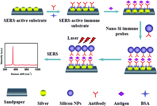 |
| | Fig. 1 Schematic of the SERS-based immunoassay protocol. | |
2.5 Instruments
Transmission electron microscopy (TEM, JEM-2100F, JEOL) was used to obtain the TEM images, operating at 200 kV accelerating voltage. Field-emission scanning electron microscopy (SEM, SU-70, Hitachi) was used to characterize the morphology of the SERS-active substrate, operating at 10 kV accelerating voltage. ζ-Potential measurements were performed with a nanoparticle size analyzer (Zetasizer Nano S90, Malvern). Ag film was deposited by the magnetron sputtering coating equipment (TA13-XD) at 1.4 Pa sputtering pressure and 50 W sputtering power. The SERS signals were measured by using a Raman spectrometer (BWS415, B&W Tek Inc.) which is equipped with a semiconductor laser (785 nm, 499.95 mW), a grating of 1200 lines per mm, and a charge coupled device (CCD, 2048 pixels) detector. An Immunoassay Analyzer (UniCel DxI 800, Beckman Coulter, Inc.) was operated to implement the chemiluminescence immunoassay (CLIA) for the tumor markers.
3 Results and discussion
3.1 Characterization of Si NPs and immune probes
TEM images of the SiO2-coated Si NPs are shown in Fig. 2(a) and (b). It is clearly illustrated that the Si NPs have a wide range of sizes from 50 to 200 nm and the SiO2 coated layer is very thin with an average thickness 4 ± 1 nm. The HRTEM and the EDS pattern of the SiO2-coated Si NPs are shown in Fig. 2(c) and (d), respectively. Fig. 2(c) clearly displays that the SiO2-coated Si NPs consist of single crystal silicon with a lattice spacing of 3.13 Å and a fusion SiO2 layer. Fig. 2(d) indicates that there are two constituent elements, Si and O, in the SiO2-coated Si NPs. The schematic of modifying APTMS on the surface of SiO2-coated Si NPs is shown in Fig. S1.† Concretely, as mentioned in section 2.2, APTMS ((H3CO)3–Si–(CH2)3NH2) was hydrolyzed to form (HO)3–Si–(CH2)3NH2 in 4:1 ethanol/water solution. Meanwhile, the Si–O–Si bond was formed by the dehydration condensation reaction between the Si–OH of SiO2 layer and Si–OH produced by APTMS hydrolysis. Thus, the amino groups of the SiO2 layer were realized through Si–O–Si bonds.34,35
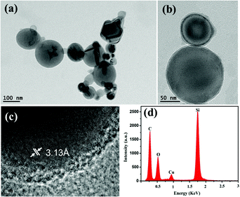 |
| | Fig. 2 (a, b) TEM images, (c) HRTEM image and (d) EDS pattern of SiO2-coated Si NPs. | |
The surface modification properties of SiO2-coated Si NPs have been analyzed by their ζ-potential measurements. The SiO2-coated Si NPs, APTMS-modified SiO2-coated Si NPs and the immune probes are distributed in PBS (pH = 7.0) and their zeta potentials are shown in Table 1. The unmodified SiO2-coated Si NPs possess a negative surface potential of about −42.8 mV. After the SiO2-coated Si NPs were modified, the ζ-potential of APTMS-modified SiO2-coated Si NPs is about −28.3 mV, which shows that the positively charged amino groups caused the surface potential to lower by linking with Si–OH of SiO2-coated Si NPs. And, by linking detecting antibodies with APTMS-modified SiO2-coated Si NPs, the surface potentials of immune probes display obvious decreases (>12 mV), comparing with that of their original parent, which verifies that the anti-PSA antibodies, anti-AFP antibodies and anti-CA19-9 antibodies are bonded to the surfaces of the APTMS-modified SiO2-coated Si NPs, respectively. And moreover, after each modification step, the size distributions of the hydrated particles had been measured and their DLS spectra are shown in Fig. S2.† In terms of variation of the hydrodynamic diameter of SiO2-coated Si NPs, APTMS-modified SiO2-coated Si NPs and immune probes, it further confirmed that APTMS-modified SiO2-coated Si NPs and immune probes were successfully prepared.
Table 1 ζ-Potential measurements
| Sample |
Zeta-potential (mV) |
| SiO2-coated Si NPs |
−42.8 ± 2.6 |
| APTMS-modified SiO2-coated Si NPs |
−28.3 ± 2.3 |
| PSA immune probes |
−16.4 ± 1.9 |
| AFP immune probes |
−14.7 ± 0.9 |
| CA19-9 immune probes |
−16.0 ± 1.3 |
3.2 Characterization of SERS-active substrates
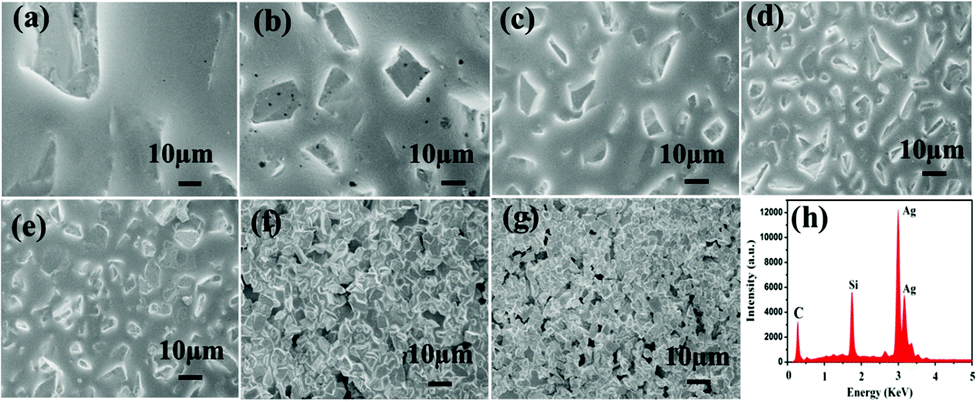
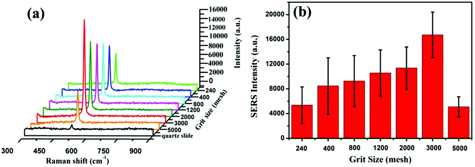
As is well known, the SERS performance of Ag film seriously depends on its surface morphology such as roughness, thickness and construction.36–38 In our experiments, SiC sandpaper was chosen as template to deposit Ag film for fabricating the SERS-active substrates. Fig. 3(a)–(g) gives the SEM images of the SiC@Ag SERS-active substrates with silver films of 200 nm thickness on sandpapers with a range of grit sizes from 240 to 5000 mesh. It is clearly seen that the sizes of grains on the surface of SiC@Ag SERS-active substrates decrease with increasing grit sizes but the density of grains increases inversely. The EDS pattern (Fig. 3(h)) shows that there are three constituent elements, Ag, Si and C, in the SERS-active substrates. Further characterizing the SERS performance of as-fabricated substrates, the SERS spectra of Si NPs dropped on the substrates were measured and shown in Fig. 4(a). It can be found that the SERS spectra display evident fingerprint characteristics, i.e., the main Raman peak at 520 cm−1 is ascribed to the ν (Si–Si) stretching mode.39 And the peak intensities at 520 cm−1 of the Si NPs increase with an increase of the mesh size of sandpaper and arrived at a maximum at the 3000 mesh size. Fig. 4(b) gives the average intensities of the SERS signals at eight test dots on the surface of SiC@Ag SERS-active substrates. Obviously, the SiC@Ag SERS-active substrate with the sandpaper of 3000 mesh exhibited the strongest SERS signal. It also confirmed the morphology-dependent SERS characteristic of the as-fabricated substrates, in detail, there are more “hot spots” on the SERS substrates with a large mesh due to the smaller size of grain and the smaller gap between grains. It should be noted, however, the SERS-active substrate fabricated by the sandpaper of 5000 mesh exhibited the worst SERS performance due to a smooth silver film deposited on the sandpaper. Thus, the SERS-active substrates with the sandpaper of 3000 mesh were used in our further experiments.
 |
| | Fig. 3 SEM images of silver film coated sandpaper with different meshes of (a) 240 mesh, (b) 400 mesh, (c) 800 mesh, (d) 1200 mesh, (e) 2000 mesh, (f) 3000 mesh and (g) 5000 mesh. (h) EDS of silver film deposited sandpaper. | |
 |
| | Fig. 4 (a) The SERS spectra and (b) the average SERS intensities of SiO2-coated Si NPs on the SERS-active substrates with different grits of sandpapers. The black curve is the Raman spectrum of the SiO2-coated Si NPs on the quartz slide. | |
To evaluate the SERS performance of the SERS-active substrate with the sandpaper of 3000 mesh, its enhancement factor (EF) is calculated by using the following equation:40–42
| EF = (ISERS/Ibulk) × (Nbulk/NSERS) |
where
ISERS and
Ibulk are the integrated intensities of the same Raman band of Si at 520 cm
−1 in the SERS spectrum and bulk Raman spectrum, respectively;
Nbulk and
NSERS represent the number of Si atoms on the quartz slide and the SERS-active substrate within the laser spot, respectively. The diameter of the laser spot was calculated to be 1.473 μm using the equation:
43Ddiameter = (
λ/NA) × 1.22, in which
λ and NA are 785 nm and 0.65 for the specifications of the Raman spectrometer, respectively. To calculate
Nbulk, the areal density of the Si atom is first estimated by dropping 100 μL of the SiO
2-coated Si NP suspension (87 mM) on the quartz slide with an area of 100 mm
2, and
Nbulk = 8.9 × 10
10 is obtained for the area above the laser spot. Similarly,
NSERS = 5.48 × 10
6 is obtained by dropping 20 μL of the SiO
2-coated Si NP suspension (10.7 mM) on the SERS-active substrate with an area of 100 mm
2. And from
Fig. 4(a),
Ibulk and
ISERS are obtained to be 6.2 × 10
3 and 1.2 × 10
5, respectively. As a result, the EF value of the SERS-active substrate is 3.14 × 10
5.
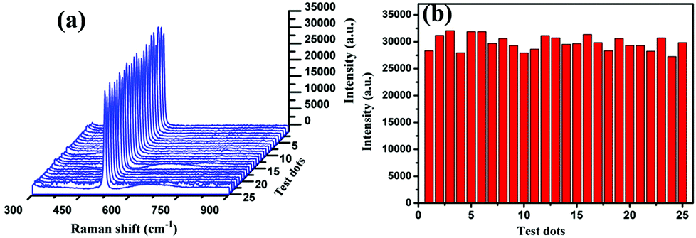
In addition, to evaluate the uniformity of the SERS-active substrate with the sandpaper of 3000 mesh, 20 μL of the SiO2-coated Si NP suspension was dropped on the SERS-active substrate with an area of 100 mm2, after drying in a gentle flow of argon gas, and the SERS spectra of Si NPs at 25 random test dots on the substrate were measured. As shown in Fig. 5(a), the measured SERS spectra are almost same. Fig. 5(b) gives the corresponding intensities of the SERS peaks at 520 cm−1 in the above 25 spots, and shows an average intensity value of ∼29817 ± 1347 with a relatively small standard deviation. It clearly demonstrates that the SERS-active substrate has an excellent uniformity although the Ag film is decorated on the rough sandpaper.
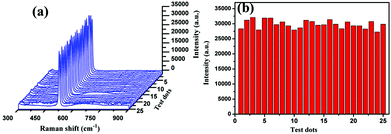 |
| | Fig. 5 (a) SERS spectra of SiO2-coated Si NPs (20 μL) at 25 random test dots on the SERS-active substrate with an area of 100 mm2; (b) the intensities of the Raman peaks at ∼520 cm−1 corresponding to the SERS spectra of the above 25 random spots. | |
3.3. SERS-based immunoassay of tumor markers
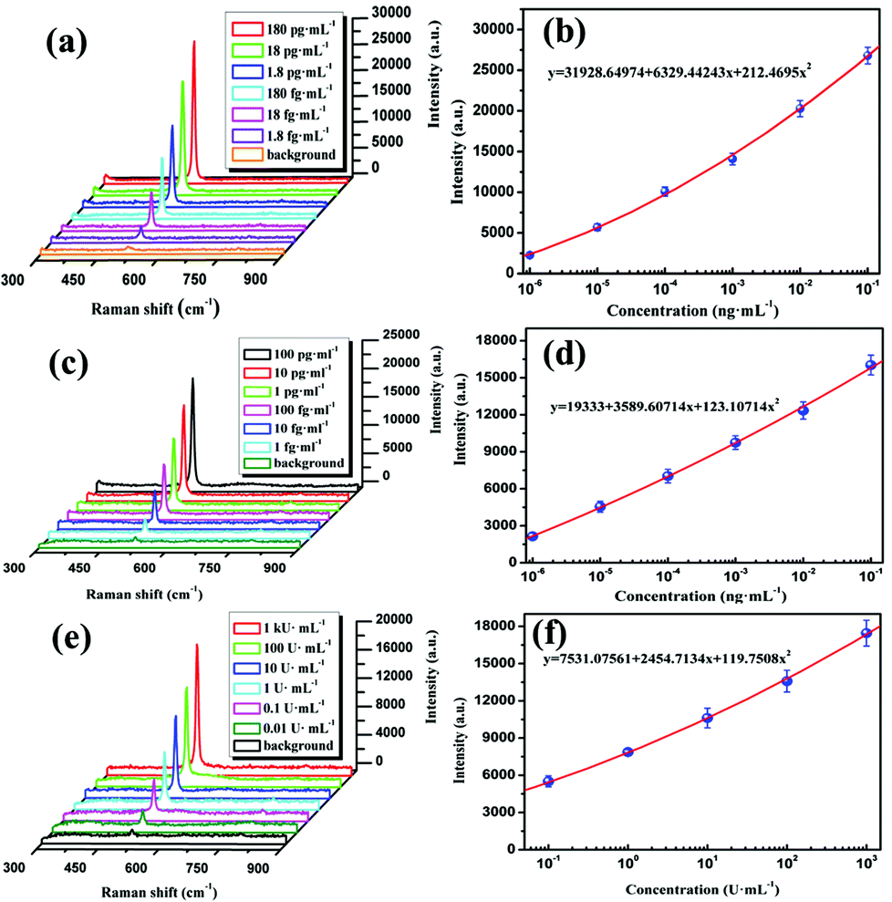
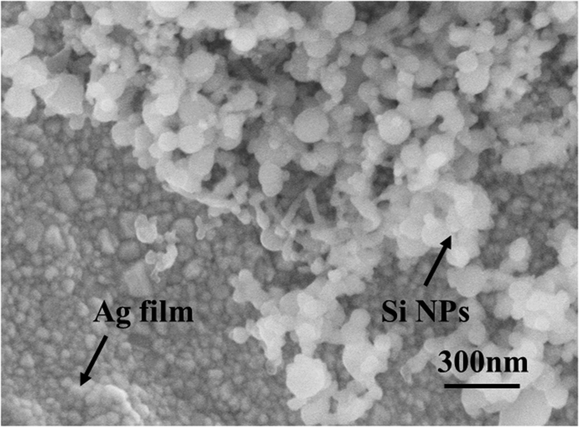
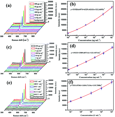
In our experiment, the tumor markers PSA, AFP and CA19-9 were detected by using the SERS-based immunoassay protocol described in section 2.5. Firstly, the saturated antibody concentration captured on the substrate should be estimated by the steps described in the ESI.† As shown in Fig. S3,† the saturated antibody concentration of PSA is ∼2.5 mg mL−1. In the same way, the saturated antibody concentrations of AFP and CA19-9 are about 2.0 mg mL−1 and 1.5 mg mL−1. Then the SERS spectra of Si NPs in the sandwich immune complexes with various concentrations of antigens are measured for setting the standard dose–response curve of antigens. As shown in Fig. 6(a), it is found that the intensities of the Raman peak at 520 cm−1 decrease with decreasing PSA concentration up to an extremely weak baseline corresponding to the blank sample. And the change of peak intensity as a function of PSA concentration is presented in Fig. 6(b). It is found that the SERS intensity of the designated peak is quadratically changed with the concentration of PSA by fitting equation y = 31928.64974 + 6329.44243x + 212.46958x2, and the LOD of 1.79 fg mL−1 can be estimated using the blank determination method.44 Similarly, Fig. 6(c) and (e) give the SERS spectra of Si NPs for different concentrations of AFP and CA19-9, the corresponding dose–response curves are shown in Fig. 6(d) and (f), respectively. From Fig. 6(d) and (f), LODs of AFP and CA19-9 are 0.46 fg mL−1 and 1.3 × 10⁻³ U mL−1, respectively. Such high detection sensitivity might be attributed to the novel immune probe prepared by Si NPs as Raman tags and the SERS-active substrate fabricated by the sandpaper. It is the sandwich immune structure, as shown in Fig. 7, that bring enormous SERS “hot spots” between the adjacent Ag NPs and leads to the distinct Raman enhancement. In addition, the upper detection limitation of the immunoassay is also important for the detection of the real sample. As described in the ESI,† in our experiments, the upper detection limitation of PSA and AFP were obtained to be 71.87 ng mL−1 and 95.75 ng mL−1, respectively. As for the case of CA19-9, the maximal dose of CA19-9 was measured to be 1000 U mL−1 (Fig. 6(f)), which could be set as the upper detection limit of CA19-9 due to the maximal dose limit of the purchased sample.
 |
| | Fig. 6 SERS spectra of Si NPs for the different concentrations of (a) PSA, (c) AFP and (e) CA19-9, and the corresponding dose–response curves of (b) PSA, (d) AFP and (f) CA19-9. The background spectra in (a), (c) and (e) were measured for the blank samples without target proteins. | |
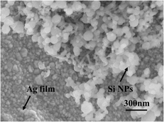 |
| | Fig. 7 SEM image of the sandwich immunoassay structure consisting of the nano-Si immune probes and SERS-active immune substrate. | |
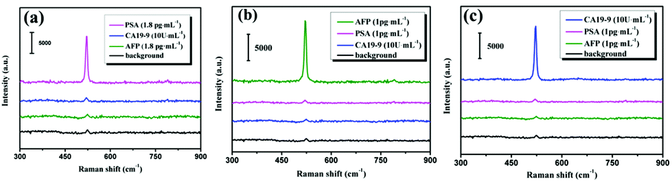
Next, taking into account to exclude false positive signals without any immune recognition, the immunological specificity of the proposed SERS-based immunoassay protocol was examined. In the experimental aim to target antigen PSA, the non-specific AFP and CA19-9 corresponding to the anti-PSA antibody are employed and the results of the specificity tests are shown in Fig. 8(a). It demonstrates that the strong characteristic SERS signal of Si NPs was generated only in the case of the immunoassay of PSA, while very weak signals (even a background noises) were obtained for non-specific AFP and CA19-9. Similarly, for the target antigens AFP and CA19-9, their specificity tests were also done and depicted in Fig. 8(b) and (c), respectively. Therefore, our SERS-based immunoassay protocol performs high immunologic specificity.
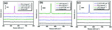 |
| | Fig. 8 SERS spectra of Si NPs in the specificity immunoassay for (a) PSA, (b) AFP and (c) CA19-9. Three black curves at the bottom represent the background signals without any target antigen. | |
3.4 SERS-based immunoassay for tumor markers in human serum
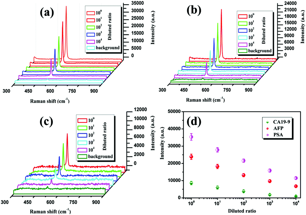
As a practical example to evaluate the clinical application possibility of the above immunoassay protocol, the blood sample of a healthy adult man at age 55 was centrifugated for 5 min at 3000 rpm, then the serum supernatant was saved at −20 °C for use later. In our experiment, the saved serum was diluted with PBS at room temperature to prepare 5 serum samples (S1–S5) with a 10-fold dilution ratio from 1 to 10000. Subsequently, according to the proposed SERS-based immunoassay protocol, the SERS spectra of Si NPs were recorded for detection of PSA, AFP and CA19-9 in the serum samples and shown in Fig. 9(a)–(c), respectively. We can see that the SERS peak intensities are gradually decreased with an increase of the dilution ratio of the serum samples. Furthermore, to eliminate measurement errors, the SERS peak intensities were obtained by averaging seven recorded data in the experiments and shown in Fig. 9(d). Then the concentration of tumor markers in each serum sample can be determined from the standard dose–response curves in Fig. 6 and is listed in Table 2. To demonstrate the validity of the proposed SERS-based immunoassay protocol, the concentrations of tumor markers were also measured by CLIA for the same serum samples and the detection values are listed in Table 2. It can be clearly seen that the results obtained by the SERS-based immunoassay are consistent with that of CLIA and display higher detection sensitivities. However, the detection values of the SERS-based immunoassay are generally lower than that of CLIA for all samples with different dilution ratios R, which could be because there were fewer immune probes bound with antigens in the washing processes. It will be further investigated in our laboratory for a better understanding of the SERS-based immunoassay.
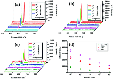 |
| | Fig. 9 SERS spectra of Si NPs corresponding to (a) PSA, (b) AFP and (c) CA19-9 in the serum samples with different of dilution ratios; (d) the intensities of SERS peaks at 520 cm−1 extracted from the above SERS spectra. | |
Table 2 Detection results
| Detected tumor markers |
Serum samples (R) |
SERS-based immunoassay |
CLIA |
| PSA (concentration/ng mL−1) |
S1 (R = 100) |
3.41481 |
3.61 |
| S2 (R = 101) |
0.21954 |
0.23 |
| S3 (R = 102) |
0.01836 |
0.02 |
| S4 (R = 103) |
0.00179 |
— |
| S5 (R = 104) |
0.00017 |
— |
| AFP (concentration/ng mL−1) |
S1 (R = 100) |
2.51189 |
2.7 |
| S2 (R = 101) |
0.18833 |
0.2 |
| S3 (R = 102) |
0.01349 |
— |
| S4 (R = 103) |
0.00097 |
— |
| S5 (R = 104) |
0.00009 |
— |
| CA19-9 (active/U mL−1) |
S1 (R = 100) |
2.69013 |
3.0 |
| S2 (R = 101) |
0.23425 |
— |
| S3 (R = 102) |
0.02244 |
— |
| S4 (R = 103) |
0.00209 |
— |
| S5 (R = 104) |
0.00018 |
— |
Conclusions
In this work, nano-Si immune probes and SiC@Ag SERS-active immune substrates have been fabricated and used for the SERS-based immunoassay of tumor markers in human serum. The proposed SERS-based immunoassay protocol has demonstrated high detection sensitivity and excellent biological specificity. For example, the immunoassay results of PSA, AFP and CA19-9 gave LODs as low as 1.79 fg mL−1, 0.46 fg mL−1 and 1.3 × 10⁻³ U mL−1, respectively. And the control experiments for non-specific antigens exhibited superior selectivity for the detection of PSA, AFP and CA19-9. Furthermore, the availability of the SERS-based immunoassay protocol has been checked by a practical test using a male blood sample. And the experimental results confirm that the detection values of the SERS-based immunoassay can be comparable to that of CLIA. Besides the high sensitivity detection of tumor markers, low cost and less time-consuming nature, there are also other advantages for fabrication of the nano-Si immune probes and the SiC@Ag SERS-active immune substrate. In a word, it is expected that the designed immunoassay protocol has great potential applications for clinical diagnostics.
Acknowledgements
This work was supported by the National Natural Science Foundation of China (Grant Nos. 61320106014, 61335011, 61275153, and 81370165), Ningbo Science and Technology Innovation Team Program (Grant No. 2014B82002), and the K. C. Wong Magna Foundation of Ningbo University, China.
Notes and references
- L. Pavesi, L. D. Negro, C. Mazzoleni, G. Franzò and F. Priolo, Nature, 2000, 408, 440–444 CrossRef CAS PubMed.
- F. Maier-Flaig, J. Rinck, M. Stephan, T. Bocksrocker, M. Bruns, C. Kübel, A. K. Powell, G. A. Ozin and U. Lemmer, Nano Lett., 2013, 13, 475–480 CrossRef CAS PubMed.
- S. Niesar, W. Fabian, N. Petermann, D. Herrmann, E. Riedle, H. Wiggers, M. S. Brandt and M. Stutzmann, Green, 2011, 1, 339–350 CrossRef CAS.
- H. Wu and Y. Cui, Nano Today, 2012, 7, 414–429 CrossRef CAS.
- A. G. Nassiopoulos, S. Grigoropoulos and D. Papadimitriou, Thin Solid Films, 1997, 297, 176–178 CrossRef CAS.
- F. Erogbogbo, K. T. Yong, I. Roy, G. X. Xu, P. N. Prasad and M. T. Swihart, ACS Nano, 2008, 2, 873–878 CrossRef CAS PubMed.
- K. Sato, H. Tsuji, K. Hirakuri, N. Fukataac and Y. Yamauchi, Chem. Commun., 2009, 25, 3759–3761 RSC.
- W. D. A. M. de Boer, D. Timmerman, K. Dohnalová, I. N. Yassievich, H. Zhang, W. J. Buma and T. Gregorkiewicz, Nat. Nanotechnol., 2010, 5, 878–884 CrossRef CAS PubMed.
- M. Ehbrecht, B. Kohn, F. Huisken, M. A. Laguna and V. Paillard, Phys. Rev. B: Condens. Matter, 1997, 56, 6958 CrossRef CAS.
- B. Zhang, H. Wang, L. Lu, K. Ai, G. Zhang and X. Cheng, Adv. Funct. Mater., 2008, 18, 2348–2355 CrossRef CAS.
- C. M. Gonzalez, M. Iqbal, M. Dasog, D. G. Piercey, R. Lockwood, T. M. Klapötkec and J. G. C. Veinot, Nanoscale, 2014, 6, 2608–2612 RSC.
- F. Erogbogbo, K. Yong, I. Roy, G. Xu, P. N. Prasad and M. T. Swihart, ACS Nano, 2008, 2, 873–878 CrossRef CAS PubMed.
- Y. Chen, H. Chen and J. Shi, Adv. Mater., 2013, 25, 3144–3176 CrossRef CAS PubMed.
- P. J. Kinnaria, M. L. K. Hyvönenb, E. M. Mäkiläa, M. H. Kaasalainenc, A. Rivinojab, J. J. Salonenc, J. T. Hirvonena, P. M. Laakkonenb and H. A. Santosa, Biomaterials, 2013, 34, 9134–9141 CrossRef PubMed.
- F. Peng, Y. Su, Y. Zhong, C. Fan, S. T. Lee and Y. He, Acc. Chem. Res., 2014, 47, 612–623 CrossRef CAS PubMed.
- B. Cho, S. Baek, H. G. Woo and H. Sohn, J. Nanosci. Nanotechnol., 2014, 14, 5868–5872 CrossRef CAS PubMed.
- X. Cheng, S. B. Lowe, P. J. Reece and J. J. Gooding, Chem. Soc. Rev., 2014, 43, 2680–2700 RSC.
- R. D. Tilley and K. Yamamoto, Adv. Mater., 2006, 18, 2053–2056 CrossRef CAS.
- Y. Zhong, F. Peng, X. Wei, Y. Zhou, J. Wang, X. Jiang, Y. Su, S. Su and S. T. Lee, Angew. Chem., Int. Ed., 2012, 51, 8485–8489 CrossRef CAS PubMed.
- Z. Iqbal and S. Veprek, J. Phys. C: Solid State Phys., 1982, 15, 377 CrossRef CAS.
- R. A. Halvorson, P. J. Vikesland and P. J. Vikesland, Environ. Sci. Technol., 2010, 44, 7749–7755 CrossRef CAS PubMed.
- A. Michota and J. Bukowska, J. Raman Spectrosc., 2003, 34, 21–25 CrossRef CAS.
- J. N. Anker, W. Hall1, O. Lyandres, N. C. Shah, J. Zhao and R. P. V. Duyne, Nat. Mater., 2008, 7, 442–453 CrossRef CAS PubMed.
- R. A. Alvarez-Puebla and L. M. Liz-Marzán, Small, 2010, 6(5), 604–610 CrossRef CAS PubMed.
- E. C. Le Ru, M. Meyer, E. Blackie and P. G. Etchegoin, J. Raman Spectrosc., 2008, 39, 1127–1134 CrossRef CAS.
- W. E. Doering and S. Nie, J. Phys. Chem. B, 2002, 106, 311–317 CrossRef CAS.
- C. Wang and C. Yu, Nanotechnology, 2015, 26, 092001 CrossRef CAS PubMed.
- S. A. Maier, M. L. Brongersma, P. G. Kik, S. Meltzer, A. A. G. Requicha, B. E. Koel and H. A. Atwater, Adv. Mater., 2001, 13, 1501–1505 CrossRef CAS.
- K. L. Kelly, E. Coronado, L. L. Zhao and G. C. Schatz, J. Phys. Chem. B, 2003, 107, 668–677 CrossRef CAS.
- L. Shu, J. Zhou, X. Yuan, L. Petti, J. Chen, Z. Jia and P. Mormile, Talanta, 2014, 123, 161–168 CrossRef CAS PubMed.
- M. H. Harpstera, H. Zhang, A. K. Sankara-Warrierc, B. H. Rayd, T. R. Wardc, J. P. Kollmarc, K. T. Carrond, J. O. Mechama, R. C. Corcoranc, W. C. Wilsona and P. A. Johnsonb, Biosens. Bioelectron., 2009, 25, 674–681 CrossRef PubMed.
- J. Ko, C. Lee and J. Choo, J. Hazard. Mater., 2015, 285, 11–17 CrossRef CAS PubMed.
- Y. Zhong, F. Peng, F. Bao, S. Wang, X. Ji, L. Yang, Y. Su, S. T. Lee and Y. He, J. Am. Chem. Soc., 2013, 135, 8350–8356 CrossRef CAS PubMed.
- J. Zhao, M. Milanova, M. M. C. G. Warmoeskerken and V. Dutschk, Colloids Surf., A, 2012, 413, 273–279 CrossRef CAS.
- K. N. Pham, D. Fullston and K. Sagoe-Crentsil, J. Colloid Interface Sci., 2007, 315, 123–127 CrossRef CAS PubMed.
- R. Zhang, B. Xu, X. Liu, Y. Zhang, Y. Xu, Q. Chen and H. B. Sun, Chem. Commun., 2012, 48, 5913–5915 RSC.
- M. Fan, G. F. S. Andrade and A. G. Brolo, Anal. Chim. Acta, 2011, 693, 7–25 CrossRef CAS PubMed.
- O. Lyandres, N. C. Shah, C. R. Yonzon, J. T. Walsh, M. R. Glucksberg and R. P. V. Duyne, Anal. Chem., 2005, 77, 6134–6139 CrossRef CAS PubMed.
- M. I. Alonso and K. Winer, Phys. Rev. B: Condens. Matter, 1989, 39, 10056 CrossRef CAS.
- N. L. Rosi and C. A. Mirkin, Chem. Rev., 2005, 105, 1547–1562 CrossRef CAS PubMed.
- Y. Liu, J. Zhou, B. Wang, T. Jiang, H. Ho, L. Lucia and P. Mormile, Phys. Chem. Chem. Phys., 2015, 17, 6819–6826 RSC.
- Z. Huang, G. Meng, Q. Huang, Y. Yang, C. Zhu and C. Tang, Adv. Mater., 2010, 22, 4136–4139 CrossRef CAS PubMed.
- Y. He, S. Su, T. Xu, Y. Zhonga, J. A. Zapienb, J. Lic, C. Fanc and S. T. Lee, Nano Today, 2011, 6, 122–130 CrossRef CAS.
- A. Shrivastava and V. B. Gupta, Chron. Young Sci., 2011, 2, 21 CrossRef.
Footnote |
| † Electronic supplementary information (ESI) available. See DOI: 10.1039/c6an00003g |
|
| This journal is © The Royal Society of Chemistry 2016 |
Click here to see how this site uses Cookies. View our privacy policy here.