 Open Access Article
Towards sustainable power sources: chitin-bound carbon electrodes for electrochemical capacitors
Adam
Kolodziej
,
Krzysztof
Fic
and
Elzbieta
Frackowiak
*
Poznan University of Technology, Institute of Chemistry and Technical Electrochemistry, Berdychowo 4, 60-965 Poznan, Poland. E-mail: elzbieta.frackowiak@put.poznan.pl
First published on 30th September 2015
Abstract
Chitin – a naturally occurring biopolymer – was employed for the first time as a binder for carbon electrodes and studied in electrochemical capacitors. Chitin-bound electrodes have shown excellent performance in neutral aqueous electrolytes up to 5 A g−1 current load with a capacitance retention of ca. 80% of the initial value for mild regimes. This study reports on the electrochemical behaviour of commercially available activated carbon (Supra 30 NORIT) bound with chitin (10% wt.) in the form of pellets, operating in two different aqueous electrolytes, i.e. 1 M Li2SO4 and 1 M KI solutions. It has been found that, for the 1 M Li2SO4 solution, the carbon electrodes demonstrate a moderate capacitance value of 65 F g−1 at 1 A g−1 current density. In 1 M KI solution merging electrical double-layer capacitance and faradaic contribution of the iodide/iodine redox couple, at the same current load, the capacitance was 175 F g−1 and it significantly increased with cycling to 260 F g−1 in the case of the chitin binder, and 300 F g−1 for the PTFE-bound electrodes taking into account the total charge supplied during capacitor discharging. Moreover, for the 1 M Li2SO4 solution, the chitin-bound electrodes display slightly better charge propagation than the PTFE-bound ones, whereas for the 1 M KI solution, the energy of the capacitor has been improved by 1 W h kg−1. Considering the rather negative impact of the commonly used binding fluoropolymers on the environment, chitin may become a great alternative for the development of cheap and environmentally benign electrochemical capacitors, while preserving their mechanical and electrochemical performance. Additionally, fluorine-based (e.g. PVDF or PTFE) electrodes are more hydrophobic and thus electrolyte penetration into the bulk of electrodes is unfavoured. It is noteworthy that the formation of a chitin complex with electrochemically generated iodine, which has a tendency to leave the system, may enhance the reversibility of the iodide/iodine redox couple and improve both the capacitance value as well as the cycle life.
1. Introduction
In response to the depletion of natural resources, energy has become a subject of particular interest of the scientific community. Among a number of devices used to store energy, electrical double-layer capacitors (EDLCs) have gained major significance because of their unusual features.1,2 EDLCs can be charged and discharged within seconds owing to the storage mechanism based on the electrostatic attraction of ions at the interface between the electrode and the electrolyte.3 Moreover, the lack of a typical redox process occurring at the electrode surface or in the electrode bulk leads to excellent cycle life of EDLCs (even up to 1 million cycles), especially when compared to other energy storage devices (up to a few thousands cycles for batteries).4 All these advantages result in the application of electrochemical capacitors, especially when reliable and high power sources are needed.5In the last decade, much attention has been paid to the economic and environmental aspects of EDLCs. A major part of the work has been particularly devoted to the development of novel carbonaceous materials produced from natural, well-abundant and cheap substrates, e.g. coconut shells,6 tobacco stems,7 coffee grounds,8 or banana fibers.9 Activated carbons produced from biomass have no negative impact on the environment as they may follow the biogeochemical cycle of carbon and do not require the synthesis of hazardous precursors. Moreover, they have several unique properties which are useful in electrochemical energy conversion and storage systems, especially in supercapacitors. A variety of surface functionalities influencing the structural and interfacial properties such as wettability or redox-activity (e.g. from oxygen or nitrogen) widely discussed elsewhere10 make them irreplaceable choices for green power sources.
The interfacial character of energy storage in electrochemical systems also provokes the development of electrolyte-related issues. As the energy stored in electrochemical capacitors depends on the square of voltage, this issue seems to be a crucial one. Obviously, water-based electrolytic solutions are recognized to be environmentally friendly and should be considered as cost-effective ones especially in terms of the device assembling process; contrarily to organic electrolytes, aqueous solutions are highly conductive, not sensitive to air/oxygen or humidity contaminants and do not require special conditions for handling and manipulation. Unfortunately, the operational potential window of aqueous solutions is limited by water decomposition, hence organic-based solvents providing ca. 2.7 V of effective voltage are widely applied on the industrial scale at the moment. However, there are several approaches to solve low voltage of aqueous electrolytes, providing a competitive compromise between moderate energy and excellent power profiles.11
Apart from conventional aqueous and acetonitrile/propylene carbonate based electrolytic solutions, ionic liquids have been proposed as a new type of electrolyte, especially in order to extend the available working voltage (when compared to aqueous electrolytes)12,13 and to make the performance safer and more sustainable (compared to organic electrolytes)14,15 but their commercial application is yet limited by high price.
Making the supercapacitor technology more environmentally friendly requires another issue to be considered such as selection of the electrode material binder, which commonly consists of fluorine-rich polymer chains. It has been found that the exposure to fluorocarbons may result in acute lung injury and alveolar collapse.16 Moreover, (for recycling purposes) the degradation of fluoropolymers, such as PTFE, requires highly dangerous ionizing radiation.17 At present, several fluorinated polymers such as polytetrafluoroethylene (PTFE) and polyvinylidenedifluoride (PVDF) are widely used as binders for carbon electrodes.18 The use of PVDF–hexafluoropropylene (PVDF–HFP)19 and Nafion20 was also reported, however their application is expensive and still involves fluorine-based polymers. To date, only a few reports concerning the replacement of fluorine-based polymeric binders by eco-friendly alternatives have been provided. To face this issue, sodium-carboxymethyl cellulose (CMC) was proposed as a relatively cheap and eco-friendly alternative for fluorinated binders.21,22 The water solubility of CMC allows preparing a water suspension of binder and avoiding toxic organic solvents. However, this solubility limits its application to organic- and ionic liquid-based electrolytes and excludes its use in aqueous media.
Chitin, being a linear polysaccharide composed of (1–4)-linked 2-acetamido-2-deoxy-β-D-glucopyranose units, is considered as the second most abundant form of polymerized carbon found in nature.23 One may find it mainly in shrimp shells24 but also in crustaceans, molluscs, insects, fungi, some algae and other related organisms.25,26 It is also a by-product in many fields with the total ‘production’ level reaching ca. 10 billion tons every year.25 Considering the fact that chitin is insoluble in most common solvents including water,27 it appeared to be an interesting approach to introduce it as a binder for carbon electrodes operating in environmentally friendly aqueous solutions.
Only a few procedures of chitin dissolution have been reported so far.28 It was shown that chitin is soluble in 9% solution of lithium chloride in 1-methyl-2-pyrrolidinone (NMP) or N,N-dimethylacetamide (DMAc).29,30 The addition of LiCl is essential to enable the formation of a weak complex between lithium cations with NMP, whereas the chloride anion destabilizes the labile protons within the chitin structure, responsible for insolubility of chitin in several solvents. Destabilized intra- and inter-molecular hydrogen bonds result in a change of the chitin crystalline structure and make it soluble in Li+/NMP solution. It is worth noting that it is also possible to dissolve chitin in the so-called calcium solvent, i.e. solution of calcium dichloride in methanol.31
Moreover, it has to be pointed out that chitin is very often confused with chitosan; indeed, chitosan is prepared by deacetylation and depolymerisation of native chitin, however, one cannot consider these compounds as substitutes and should recognize chitosan as a soluble derivative of chitin. One should also note that chitosan solubility is usually achieved by deacetylation in strong alkali solutions, hence, the final product very often contains a remarkable amount of alkaline impurities.
This study presents the preparation of chitin-bound carbon electrodes and their electrochemical performance in aqueous electrolytes. An activated carbon material characterised by a specific porosity (rather microporous) was applied. Typical pseudocapacitive materials, such as metal oxides and electrically conducting polymers, were not considered as they cannot provide satisfactory long-term stability, required to be applied at commercial scale. The performance of the prepared carbon electrodes was investigated in electrochemical capacitors operating in 1 M Li2SO4 and 1 M KI electrolytic solutions.
2. Experimental
2.1. Chemical reagents
Chitin from shrimp shells (practical grade, powder), lithium chloride (anhydrous, free-flowing, Redi-Dri™, ReagentPlus®, 99%), 1-methyl-2-pyrrolidinone (CHROMASOLV® Plus, for HPLC, ≥99%), lithium sulphate monohydrate (ACS reagent, ≥99.0% dry basis), and potassium iodide (puriss. p.a., reag. ISO, reag. Ph. Eur., ≥99.5%) were purchased from Sigma Aldrich and were used as received. The commercially available activated carbon DLC Supra 30 (NORIT) was used as the active material, and the Super C65 carbon black (TIMCAL) was used as the conductive agent.2.2. Instrumentation
The electrochemical investigations were carried out in two- and three-electrode cells. The current collectors were made of stainless steel (316L), and glass fibre paper (Whatman GF/A) was used as the separator. Cyclic voltammetry, galvanostatic charge/discharge and potentiostatic electrochemical impedance spectroscopy measurements were performed on a VMP3 multichannel potentiostat/galvanostat (Biologic, France).Scanning Electron Microscopy (SEM, HITACHI S-3400N) was employed to investigate the morphology of the chitin-bound electrodes.
The porous texture and BET specific surface area, SBET, of the electrodes were determined from nitrogen adsorption/desorption isotherms recorded at 77 K using an ASAP2020 (Micromeritics). Prior to the measurements, the samples (around 30 mg) were degassed under vacuum for 24 h at 100 °C. The pore size distribution (PSD) was estimated based on the two-dimensional non-local density functional theory (2D-NLDFT) model assuming an energetic heterogeneity of carbon pores.32,33
Contact angle measurements were performed on a Data Physics Contact Angle System OCA.
2.3. Procedure for electrodes preparation
Electrodes were prepared using 85 wt% of activated carbon, 5 wt% of carbon Super C65 (TIMCAL) and 10 wt% of chitin. The electrodes were prepared as follows.In order to dissolve chitin, a 9% solution of lithium chloride in NMP was prepared according to the procedure published elsewhere.22 Briefly, appropriate amounts of LiCl and NMP were placed in a flask and stirred at 90 °C under reflux for one hour. Subsequently, the clear solution was cooled down to room temperature and chitin was added and the mixture was stirred during 24 hours. Then, the appropriate amount of activated carbon (85%) and conductive agent (5%) with respect to the chitin mass was added, and the obtained mixture was stirred at ambient temperature for 48 hours. Later on, NMP was evaporated under vacuum and the resulting material was washed a few times with deionised water to remove LiCl residues. Electrodes in the form of pellets (6 to 8 mg) of 0.785 cm2 geometric surface area were pressed under 7000 kg cm−2 for 90 seconds and then dried in a vacuum at 120 °C for 8 hours.
3. Results and discussion
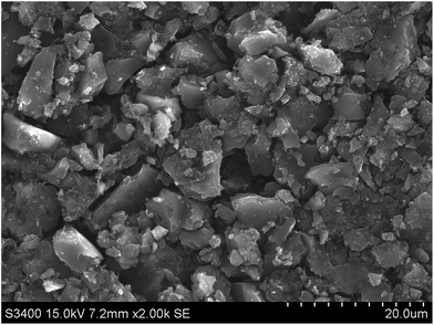
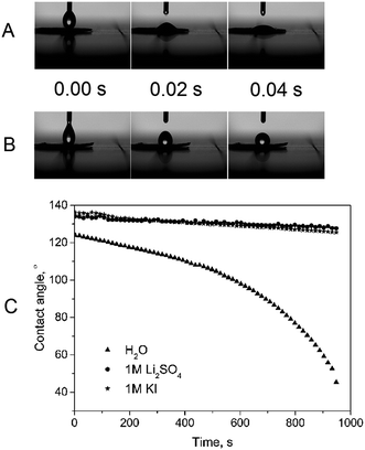
In order to estimate the morphology of the prepared electrode, several SEM images have been taken. As shown in Fig. 1, the materials are homogeneously distributed with no sign of agglomeration. No signature of electrode cracking was observed either. Moreover, we did not notice any significant difference between the morphology of PTFE and chitin-bound electrodes, hence, the procedure for electrode preparation with chitin is a competitive one in terms of obtaining well-dispersed electrode components.Since efficient charge storage may occur only at the electrode/electrolyte interface, wettability seems to be of the greatest significance. PTFE and PVDF-bound electrodes suffer from moderate or even poor wettability (fluorine-based polymers usually enhance the hydrophobic properties of the surface). In order to follow the electrode ability for being wetted, the contact angle has been measured using deionised water, 1 M Li2SO4 and 1 M KI (Fig. 2) solutions. The contact angle measurements demonstrated obvious differences between chitin- and PTFE-bound electrodes. In the case of the commercially used PTFE, the electrode wettability is very poor, and the electrode has to be pre-treated with the electrolyte solution or a period of time is required to observe the best performance. The application of chitin may enable us to overcome this disadvantage; the chitin-bound electrode shows excellent wettability (a few ms) and aqueous electrolyte affinity, therefore, it was not possible to measure the exact contact angle for this material. The improved wettability observed for the chitin-bound electrodes may be related to the presence of polar amide groups in the chitin structure.34 It has to be noted that dynamic measurements demonstrated a similar contact angle change vs. time, whereas for deionized water the dependence changes rapidly, approaching 40° after 980 s. This phenomenon is probably related to the viscosity of the solutions (the lowest for deionized water and similar for electrolytic solutions) as well as to their polarity. Finally, this result indicated that the chitin-bound electrode has more hydrophilic properties than PTFE or PVDF-bound ones and may demonstrate remarkably better electrochemical performance.
Fig. 3 presents the nitrogen adsorption isotherm and pore size distribution (PSD) for the materials investigated. The highest quantity of adsorbed nitrogen has been recorded for the raw carbon material but the binder did not impact the average pore size and pores with the diameter of ca. 7 Å have the highest contribution to the specific surface area. Obviously, an addition of binder results in remarkable loss of accessible surface area, however, there is a negligible difference in pore-blocking when compared to the PTFE-bound electrode. This suggests that – similarly to PTFE – chitin has an impact on the specific surface area, but there is still a significant part of microporosity accessible for ions from electrolyte solution.
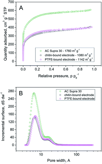 | ||
| Fig. 3 (A) Nitrogen sorption isotherms of the Supra 30, PTFE-bound electrode, and chitin-bound electrode (B) pore size distribution of materials estimated by 2D-NDLFT. | ||
As mentioned before, the application of chitin as a binder could be an interesting approach to develop environmentally-friendly and safe electrochemical capacitors. Nevertheless, the final performance is always a key point to estimate the usefulness, therefore electrochemical measurements of chitin-bound electrodes were conducted in aqueous solutions of 1 M Li2SO4 and 1 M KI and compared to commonly used PTFE-bound electrodes. Two different kinds of solutions were selected because of their special features reported elsewhere.35 Briefly, aqueous solutions of Li2SO4 allow reaching high voltage values of 2 V whereas KI or NaI electrolytic solutions supply high capacitance values (originating from redox activity of the I−/I2 couple) accompanied by good charge propagation and excellent cyclability.36
Fig. 4 shows cyclic voltammograms of chitin-bound carbon electrodes in aqueous electrolytes of 1 M Li2SO4 and 1 M KI, compared to PTFE-bound carbon electrodes at a scan rate of 10 mV s−1. Both types of the electrodes display comparable electrochemical performance with the average capacitance of 75 F g−1 (Fig. 4A). Additionally, in the case of 1 M Li2SO4 there is no response from the redox reaction; box-like shapes of cyclic voltammograms reflect purely capacitive behaviour. No obvious evidence for decomposition of the electrode or the electrolyte can be observed either. Different responses were recorded in the case of 1 M KI (Fig. 4B); the pseudocapacitive character of the curves is related to the faradaic reactions of the iodide species. The high value of capacitance (ca. 160 F g−1 at 10 mV s−1) and ‘deteriorated’ shape of the CV profile result from an oxidation of iodides to iodine and formation of polyiodides (I3− or I5−).37 It is worth noting that in both electrolytes chitin-bound electrodes demonstrated good charge propagation and reached values of capacitance similar to PTFE-bound electrodes.
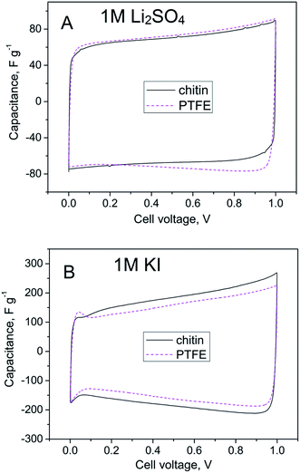 | ||
| Fig. 4 Cyclic voltammograms (10 mV s−1) of the capacitor based on the chitin-bound electrode compared to the PTFE-bound electrode in (A) 1 M Li2SO4 and (B) 1 M KI. | ||
The high value of operating voltage is a desirable feature of electrochemical capacitors because of the following dependence:
| E = ½C × U2 |
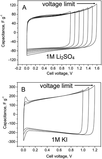 | ||
| Fig. 5 Cyclic voltammograms (10 mV s−1) of EDLCs based on chitin-bound electrodes (A) at the cut-off voltage of 1.0–1.6 V in 1 M Li2SO4 (B) at the cut-off voltage of 1.0–1.2 V in 1 M KI. | ||
The capacitor built with activated carbon electrodes bound with chitin demonstrated capacitive behaviour with a remarkable contribution from I−/I2 faradaic reactions, taking place on the positive electrode.30 The current response from several redox reactions at higher voltages applied indicated a higher content of electrogenerated iodine as well as recombination of iodine and iodides in the electrolyte bulk resulting in polyiodide species formation (I3−, I5−, etc.). In previous work38 we have reported that iodides and iodine may interact with the activated carbon surface with C–I bond formation. It suggests that a part of pseudocapacitance may originate also from the electrode bulk. In this regard, the binder should play a significant role as well. This issue will be discussed later.
Apart from typical qualitative voltammetry studies, the behaviour of mentioned electrodes was also studied by charging and discharging measurements using the constant current density method (Fig. 6) with various current loads (100 mA g−1 until 5 A g−1). These results suggest a comparable performance of chitin- and PTFE-bound electrodes, especially at low current densities (i.e. up to 1 A g−1 with the capacitance of ca. 75 F g−1 for 1 M Li2SO4 solution and 150–175 F g−1 for 1 M KI solution). However, chitin-bound electrodes better retained their initial capacitance along the current density (ca. 80% of initial values), thus, one may consider an extraordinary charge propagation in this electrode. Moreover, retained capacitance values even at high current regimes suggest that chitin-bound electrodes are well-soaked in the electrolyte, the interface is well-developed and the reversible charge accumulation occurs effectively.
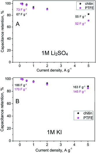 | ||
| Fig. 6 Capacitance retention and values of capacitance versus current density in (A) 1 M Li2SO4 and (B) 1 M KI. | ||
One of the most important advantages of electrochemical capacitors is their long cycle life. To study that aspect, a constant current charging/discharging mode (at 2 A g−1) has been used for 10![[thin space (1/6-em)]](https://www.rsc.org/images/entities/char_2009.gif) 000 cycles (Fig. 7). It is shown that chitin-bound electrodes display extremely good cycling stability, comparable to those bound with PTFE. In the case of 1 M Li2SO4 solution as an electrolyte, the capacitance has been retained during cycling, hence, a good stability and inertness of chitin in the mentioned medium has been confirmed. When considering 1 M solution of KI as an electrolyte, apart from electrostatic attraction of ions, a redox reaction has to be taken into account. It has been discussed that an increase of capacitance originates mainly from the enormous activity of the I−/I2 redox couple but revealed only in a narrow potential range. It has to be mentioned that this activity of generated iodine increases with time. Obviously, generated iodine is reversibly reduced to iodides or recombines to polyiodides, but the efficiency of this process cannot be considered as 100%. The effect of iodine redox activity can be observed in the form of a peak during voltammetry experiments at low supercapacitor voltage, arising with the time or number of cycles. This peak is related to the strong activity of iodine which is either dissolved in the electrolyte solution or remains in the gas phase as the vapour equilibrium is established in the system. On the other hand, during galvanostatic cycling the redox activity of iodine is perfectly seen at the low voltage (0–0.2 V) in the form of a broad plateau (marked by an ellipse in Fig. 7C). For capacitance calculation, one cannot consider such a response as a pure capacitive one as there is no direct sloping line of voltage during the discharging process (Fig. 7C); this may lead to the overestimation of the capacitance value. However, this charge equal to capacitance can be practically used if the capacitor will be fully discharged to zero. In order to demonstrate the difference, capacitance values obtained by two calculation methods are placed in Fig. 7B. Considering the broad plateau arising at galvanostatic discharging during the 10
000 cycles (Fig. 7). It is shown that chitin-bound electrodes display extremely good cycling stability, comparable to those bound with PTFE. In the case of 1 M Li2SO4 solution as an electrolyte, the capacitance has been retained during cycling, hence, a good stability and inertness of chitin in the mentioned medium has been confirmed. When considering 1 M solution of KI as an electrolyte, apart from electrostatic attraction of ions, a redox reaction has to be taken into account. It has been discussed that an increase of capacitance originates mainly from the enormous activity of the I−/I2 redox couple but revealed only in a narrow potential range. It has to be mentioned that this activity of generated iodine increases with time. Obviously, generated iodine is reversibly reduced to iodides or recombines to polyiodides, but the efficiency of this process cannot be considered as 100%. The effect of iodine redox activity can be observed in the form of a peak during voltammetry experiments at low supercapacitor voltage, arising with the time or number of cycles. This peak is related to the strong activity of iodine which is either dissolved in the electrolyte solution or remains in the gas phase as the vapour equilibrium is established in the system. On the other hand, during galvanostatic cycling the redox activity of iodine is perfectly seen at the low voltage (0–0.2 V) in the form of a broad plateau (marked by an ellipse in Fig. 7C). For capacitance calculation, one cannot consider such a response as a pure capacitive one as there is no direct sloping line of voltage during the discharging process (Fig. 7C); this may lead to the overestimation of the capacitance value. However, this charge equal to capacitance can be practically used if the capacitor will be fully discharged to zero. In order to demonstrate the difference, capacitance values obtained by two calculation methods are placed in Fig. 7B. Considering the broad plateau arising at galvanostatic discharging during the 10![[thin space (1/6-em)]](https://www.rsc.org/images/entities/char_2009.gif) 000th cycle, the capacitance value increases with time, both for PTFE and chitin-bound electrodes. Moreover, for PTFE-bound electrodes the capacitance value is almost two times higher than the initial one (300 F g−1vs. 160 F g−1) whereas for the chitin-bound electrode this increase is less remarkable (260 F g−1vs. 160 F g−1). It may suggest that either there is no strong generation of free iodine or the iodine generated is trapped in the system. Apart from reported carbon/iodine interactions, one should assume the iodine–chitin complex formation;39 this complex may trap the iodine in the chitin structure according to the mechanism already deeply investigated and presented in Fig. 8, and enhance the cyclability by the reversible redox reaction of iodine to (poly)iodides.
000th cycle, the capacitance value increases with time, both for PTFE and chitin-bound electrodes. Moreover, for PTFE-bound electrodes the capacitance value is almost two times higher than the initial one (300 F g−1vs. 160 F g−1) whereas for the chitin-bound electrode this increase is less remarkable (260 F g−1vs. 160 F g−1). It may suggest that either there is no strong generation of free iodine or the iodine generated is trapped in the system. Apart from reported carbon/iodine interactions, one should assume the iodine–chitin complex formation;39 this complex may trap the iodine in the chitin structure according to the mechanism already deeply investigated and presented in Fig. 8, and enhance the cyclability by the reversible redox reaction of iodine to (poly)iodides.
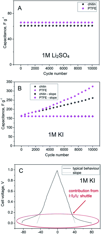 | ||
| Fig. 7 Cycle life of chitin- and PTFE-bound electrodes at 2 A g−1 in (A) 1 M Li2SO4 and (B) 1 M KI and (C) constant current charging/discharging of the PTFE-bound electrode at 2 A g−1 in 1 M KI. | ||
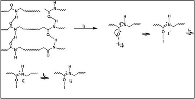 | ||
| Fig. 8 A representative scheme of the chitin–iodine complex formation.39 | ||
On the other hand, if to consider only the slope of the discharge profile, i.e. pure electrostatic attraction, the capacitance value remains stable, at the level of 160 F g−1.
More in-depth studies of electrode/electrolyte interactions have been performed by the potentiostatic electrochemical impedance spectroscopy (PEIS) method (Fig. 9 and 10). In the high frequency region (100 kHz–10 Hz) in both electrolyte solutions, the charge propagation in the chitin-bound electrode is enhanced. Equivalent series resistance (ESR) values seem to be comparable to PTFE and chitin-bound electrodes (ca. 0.42 ohm in 1 M Li2SO4 solution and 0.36 ohm for 1 M KI solution), whereas the Equivalent Distributed Resistance (EDR) differs significantly; a remarkable improvement has been observed both for electrodes operating in 1 M Li2SO4 solution (0.6 ohm for the chitin bound electrode vs. 2 ohm for the PTFE bound electrode) and in 1 M KI solution (0.52 ohm for the chitin bound electrode vs. 1.1 ohm for the PTFE bound electrode). In the low frequency region the impedance profile is similar for both electrodes and solutions; thus, one may expect similar energy densities (for the systems with the same electrolyte) with the major difference in power profiles.
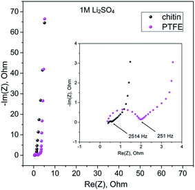 | ||
| Fig. 9 Electrochemical impedance spectroscopy measurements of chitin- and PTFE-bound electrodes in 1 M Li2SO4 in the frequency range of 100 kHz to 10 mHz. | ||
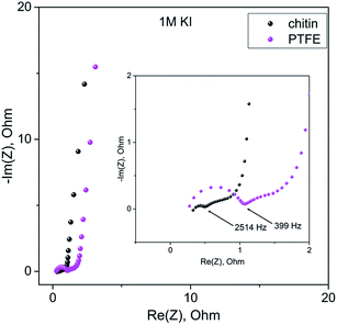 | ||
| Fig. 10 Electrochemical impedance spectroscopy measurements of chitin- and PTFE-bound electrodes in 1 M KI in the frequency range of 100 kHz to 10 mHz. | ||
In order to determine a power/energy density profile, the galvanostatic charging/discharging method has been applied and the energy and power have been calculated for the maximum voltage achieved. These results have been presented on the so-called Ragone plot (Fig. 11). This dependence shows that PTFE- and chitin-bound electrodes display comparable energy performance of ca. 2.5 W h kg−1 for 1 M Li2SO4 solution and ca. 6 W h kg−1 for 1 M KI solution, with a higher power density for chitin-bound electrode systems.
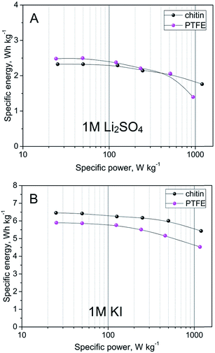 | ||
| Fig. 11 Energy density vs. power density of capacitors with chitin- and PTFE-bound electrodes in (A) 1 M Li2SO4 and (B) 1 M KI. | ||
4. Conclusions
It has been reported that chitin can be successfully applied as a binder for carbon electrodes used in electrochemical capacitors operating in 1 M Li2SO4 and 1 M KI. This solution offers an environmentally friendly device reaching the value of capacitance comparable to commonly used PTFE-bound electrodes. Moreover, chitin-bound electrodes display good wettability and charge propagation across the electrode/electrolyte interface. Application of such electrodes operating in 1 M KI solution as an electrolyte results in cyclability/stability improvement of iodine-based systems owing to a beneficial formation of the chitin–iodine complex. Power enhancement of the capacitor with chitin-bound electrodes in 1 M Li2SO4 solution was also demonstrated. Finally, chitin has been proposed as a promising binder for novel and green electrochemical capacitors, where all components are environmentally friendly and the system could be considered as sustainable. Alternatively, the insolubility of chitin in most solvents opens the doors to investigate proposed electrodes in organic electrolytes and certain ionic liquids.Acknowledgements
This work was financially supported by the project “Engineer of the Future. Improving the didactic potential of the Poznan University of Technology” – POKL.04.03.00-00-259/12, implemented within the Human Capital Operational Programme, co-financed by the European Union within the European Social Fund and Swiss Contribution within Polish-Swiss Research Programme, INGEC Project No. PSPB 107/2010.References
- R. Kötz and M. Carlen, Electrochim. Acta, 2000, 45, 2483 CrossRef.
- F. Beguin, V. Presser, A. Balducci and E. Frackowiak, Adv. Mater., 2014, 26, 2219 CrossRef CAS PubMed.
- J. R. Miller and P. Simon, Science, 2008, 321, 651 CrossRef CAS PubMed.
- A. Burke, J. Power Sources, 2000, 91, 37 CrossRef CAS.
- J. R. Miller and A. F. Burke, Electrochem. Soc. Interface, 2010, 17, 53 Search PubMed.
- M. S. Dandekar, G. Arabale and K. Vijayamohanan, J. Power Sources, 2005, 141, 198 CrossRef CAS PubMed.
- P. Kleszyk, P. Ratajczak, P. Skowron, J. Jagiello, Q. Abbas, E. Frackowiak and F. Beguin, Carbon, 2015, 81, 148 CrossRef CAS PubMed.
- T. E. Rufford, D. Hulicova-Jurcakova, Z. H. Zhu and G. Q. Lu, Electrochem. Commun., 2008, 10, 1594 CrossRef CAS PubMed.
- V. Subramanian, C. Luo, A. M. Stephan, K. S. Nahm, S. Thomas and B. Wei, J. Phys. Chem. C, 2007, 111, 7527 CAS.
- E. Frackowiak, G. Lota, J. Machnikowski, C. Vix-Guterl and F. Beguin, Electrochim. Acta, 2006, 51, 2209 CrossRef CAS PubMed.
- Q. Gao, L. Demarconnay, E. Raymundo-Pinero and F. Beguin, Energy Environ. Sci., 2012, 5, 9611 CAS.
- M. Galinski, Electrochim. Acta, 2006, 51, 5567 CrossRef CAS PubMed.
- A. Balducci, R. Dugas, P. L. Taberna, P. Simon, D. Plee, M. Mastragostino and S. Passerini, J. Power Sources, 2007, 165, 922 CrossRef CAS PubMed.
- M. Anouti and L. Timperman, Phys. Chem. Chem. Phys., 2013, 15, 6539 RSC.
- C. Arbizzani, M. Biso, D. Cericola, M. Lazzari, F. Soavi and M. Mastragostino, J. Power Sources, 2008, 185, 1575 CrossRef CAS PubMed.
- G. P. Daubert, H. A. Spiller, B. Insley Crouch, S. A. Seifert, K. E. Simone and S. C. Smolinske, J. Med. Toxicol., 2009, 5, 125 CrossRef.
- R. Premraj and D. Mukesh, Indian J. Biotechnol., 2005, 4, 186 CAS.
- Q. Abbas, D. Pajak, E. Frackowiak and F. Beguin, Electrochim. Acta, 2014, 140, 132 CrossRef CAS PubMed.
- K. M. Kim, J. W. Hur, S. I. Jung and A. S. Kang, Electrochim. Acta, 2004, 50, 863 CrossRef CAS PubMed.
- F. Lufrano and P. Staiti, Electrochim. Acta, 2004, 49, 2683 CrossRef CAS PubMed.
- A. Brandt, P. Isken, A. Lex-Balducci and A. Balducci, J. Power Sources, 2012, 204, 213 CrossRef CAS PubMed.
- A. Krause and A. Balducci, Electrochem. Commun., 2011, 13, 814 CrossRef CAS PubMed.
- X. Hu, Y. Du, Y. Tang, Q. Wang, T. Feng, J. Yang and J. F. Kennedy, Carbohydr. Polym., 2007, 70, 451 CrossRef CAS PubMed.
- A. Percot, C. Viton and A. Domard, Biomacromolecules, 2003, 4, 12 CrossRef CAS PubMed.
- P. R. Rege and L. H. Block, Carbohydr. Res., 1999, 321, 235 CrossRef CAS.
- A. Tolaimate, J. Desbrieres, M. Rhazi, A. Alagui, M. Vicendon and P. Vottero, Polymer, 2000, 41, 2463 CrossRef CAS.
- T. Sannan, K. Kurita and Y. Iwakura, Macromol. Chem., 1975, 176, 1191 CrossRef CAS PubMed.
- A. Einbu, S. N. Naess, A. Elgsaeter and K. M. Varum, Biomacromolecules, 2004, 5, 2048 CrossRef CAS PubMed.
- S. L. Williamson, R. Scott Armentrout, R. S. Porter and C. L. McCormick, Macromolecules, 1998, 31, 8134 CrossRef CAS.
- C. K. S. Pillai, W. Paul and C. P. Sharma, Prog. Polym. Sci., 2009, 34, 641 CrossRef CAS PubMed.
- R. Flores, S. Barrera-Rodriguez, K. Shirai and C. Duran-de-Bazua, J. Appl. Polym. Sci., 2007, 104, 3909 CrossRef CAS PubMed.
- J. Jagiello and J. P. Olivier, Carbon, 2013, 55, 70 CrossRef CAS PubMed.
- J. Jagiello and J. P. Olivier, Adsorption, 2013, 19, 777 CrossRef CAS.
- K. Ohyama, S. Takasago, N. Kishikawa and N. Kuroda, J. Sep. Sci., 2015, 38, 720 CrossRef CAS PubMed.
- K. Fic, G. Lota, M. Meller and E. Frackowiak, Energy Environ. Sci., 2012, 5, 5842 CAS.
- J. Menzel, K. Fic, M. Meller and E. Frackowiak, J. Appl. Electrochem., 2014, 44, 439 CrossRef CAS.
- G. Lota and E. Frackowiak, Electrochem. Commun., 2009, 11, 87 CrossRef CAS PubMed.
- E. Frackowiak, M. Meller, J. Menzel, D. Gastol and K. Fic, Faraday Discuss., 2014, 172, 179 CAS.
- S. Moulay, J. Polym. Eng., 2013, 33, 389 CAS.
| This journal is © The Royal Society of Chemistry 2015 |

