DOI:
10.1039/C5RA04355G
(Paper)
RSC Adv., 2015,
5, 46229-46239
Highly monodispersed Ag embedded SiO2 nanostructured thin film for sensitive SERS substrate: growth, characterization and detection of dye molecules†
Received
12th March 2015
, Accepted 15th May 2015
First published on 15th May 2015
Abstract
Highly monodispersed Ag embedded SiO2 nanostructured thin films are synthesized and their sensitivity towards SERS investigated. The possible mechanism for the formation of a highly monodispersed SiO2 nanostructured thin film and its self-assembled nanogap with Ag are discussed. It is found that the architecture of Ag embedded SiO2 (Ag@SiO2) are drastically influenced by precursor concentration and the reaction time. The morphology and monodispersity of the silica thin film were confirmed using FESEM and AFM. The crystallinity and existence of Ag on SiO2 were confirmed using XRD and XPS. The substrate shows enhanced SERS efficiency due to the reduced size (around 15 nm) of the Ag nanoparticles and the nano gap of (below 3 nm) between SiO2 and Ag. Based on the FDTD (finite-difference time-domain) simulation, the creation of hotspots was confirmed for the obtained nanogap. The prepared thin film possesses strong Surface Plasmon Resonance (SPR) with widely tunable peaks between 407–430 nm in the UV visible spectrum. The Ag@SiO2 nanosphere-based SERS platform provides highly enhanced effects and reveals a reproducible enhancement (EF = 7.79 × 10⁸) of R6G (Rhodamine 6G), allowing a detection limit from a 10–18 mol L−1 solution. The prepared substrate was also used to detect trace levels of melamine from a 10–8 mol L−1 solution.
1. Introduction
Plasmonic substrates offer a unique opportunity for manipulating the interaction between light and matter at the nanoscale. The assembly of plasmonic nanoparticles onto planar ensembles with short interparticle distances leads to novel and unique optoelectronic features due to long-range plasmon coupling over large areas.1 These extended plasmonic structures are proposed as advanced platforms to address biological and medical challenges. In recent years, Surface Enhanced Raman Spectroscopy (SERS) analysis has developed into a noteworthy tool in various fields such as analytical chemistry, environmental monitoring, forensics and biology due to its Localized Surface Plasmon Resonance (LSPR) in nanostructured metal surfaces.2,3 Surface Enhanced Raman Scattering (SERS) mediated by plasmonic nanostructured substrates is rapidly being established as a reliable detection and analysis spectroscopic technique in the biological and medical fields.1 Therefore, suitable substrates for SERS analysis of biological samples are most desirable. The most critical aspect of SERS measurement is the nanostructure used to enhance the Raman signal.4,5 However metal oxides are also preferred in view of their semiconducting properties, shape and size as well as their local dielectric environment for light scattering and coupling efficiency.6 The construction of novel metal nanostructured thin films has therefore developed into an increasingly important research area in the fabrication of SERS substrates.7–9 Noble metal nanostructures are commonly used for SERS studies due to their strong dependence on morphology and Localized Surface Plasmon Resonance. The functional properties of nanostructured films are largely determined by the size, morphology, surface properties and composition of the nanoparticles within the film. For practical use, such nanostructured films should have uniformity,10 roughness,11 and growth orientation.12,13 Apart from this, the gap between two nanoparticles in nanostructured films should lead to enhanced Raman amplification by creating hot spots.14 However to create such hot spots at nanoscale junctions or interstices in a facile way is the major challenge in SERS among the researchers. For fabrication of such substrates one has to control reaction parameters such as solvent, temperature, and time which will influence the particle morphology during the growth process and such delicate manipulations can be used to obtain the controlled nanostructured films. In the present study, we are able to create such nanogaps using a facile vertical deposition technique. The isotropic growth of the synthesized nanospheres agrees with the physical and chemical concepts used to control the shape of nanostructures during the growth process, and also with the electro kinetic potential in colloidal solution; insight is gained into the mechanisms of both. Thus all parameters influence the resulting particle morphology during the vertical deposition process. In respect to this the metal film over nanospheres (FON) has shown effective SERS for structures having appropriate gap and diameter ratio. A Variety of metal oxides like SiO2, Fe2O3, CuO, ZnO, and TiO2 have been used as a SERS substrates.15,16 Among them SiO2 serves as a striking supportive material and stable coating to stabilize the metallic phase and to disperse the noble metal for the formation of reliable nanostructures.17,18 Ag embedded fumed silica based substrate offers the advantage of high roughness and prevents aggregation of Ag nanoparticles, thus stabilizing the SERS effect, leading to self-assembled nanospheres. There are many reports on Ag@SiO2 nanocomposites for ultrasensitive detection with highly enhanced effects. Also prodigious methods have been used to synthesize nanospheres by chemical methods and physical techniques such as vacuum coating, sputtering and plasma etching.19–21 In all the above techniques silica plays the major role of the base layer due to its monodispersity and also acts like a template for silver deposition. Even though these techniques show highly enhanced SERS effects, only a few reports22–25 are available about the hot spots of SERS and self-assembled nanogaps. Recently Jing Chen et al.26 have reported similar results. They showed that broccoli-shaped Ag deposited on SiO2 colloidal crystal templates by physical deposition technique gives good enhancement. The present work shows the formation of nano gap and self-assembling of silver NPs between silica by simple dip coating technique for the first time. Even though the chemical deposition technique has its own drawbacks, the highest enhancement is observed in this technique as reported by Yubian Han et al.25 A Similar work by Shijia Long et al.18 also shows that R6G adsorbed on the substrate exhibits strong Raman signals, resulting from surface plasma coupling between closely spaced Ag nanoparticles. The present work, for the first time, demonstrates the creation of nanogap and high enhancement factor for detection of R6G dye on highly mono dispersed Ag embedded SiO2 nanostructured thin film. The study of adherence of silver nanoparticles and self-assembled nanogaps between silver and silica nanospheres gives a clear idea of hotspots in silver embedded silica nanospheres and the creation of these hotspots was confirmed by FDTD simulation. The growth mechanism of self-assembled nanospheres and nanogaps for fabrication of SERS substrate is discussed via morphological imagery. The role of positive and negative charges of silver nanoparticles on silica nanospheres for SERS analysis has also been investigated.
2. Experimental
2.1 Synthesis of Ag@SiO2
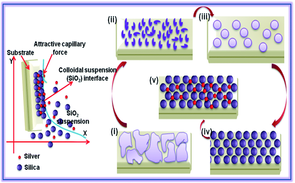
Ag@SiO2monodispersed nanospheres were synthesized by base-catalyzed hydrolysis of TEOS (tetraethyl orthosilicate) using Stober method. Prior to SERS substrate preparation, glass substrates were cut to dimensions of 1 × 2 cm2 and carefully treated by the standard cleaning process which has been described in our previous publication.27 The cleaned substrates were then dipped into the silica solution for two hours and dried at room temperature to obtain silica nanospheres. The dried substrates were immersed into Ag sol to synthesize Ag@SiO2 nanospheres. Ag sol was prepared as follows: 10 mL of 0.02 M AgNO3 was added drop by drop into a mixture of 10 mL of 0.375 M PVP and 10 mL of 0.1 M tri-sodium citrate with vigorous stirring at 80 °C until a yellow color solution (Ag hydrosol A) was obtained. The above procedure was repeated using NaBH4 as the reducing agent instead of trisodium citrate for the synthesis of Ag hydrosol B (red colour). The schematic illustration is shown in Fig. 1 for the formation of Ag@SiO2 thin film. The obtained film was further used as SERS substrate for detection of R6G and melamine. The probe molecule has been put onto film using micropipette and dried naturally.
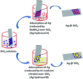 |
| | Fig. 1 Schematic illustration of formation of Ag embedded silica (Ag@SiO2) nanospheres. | |
2.2 Characterization technique
The prepared Ag@SiO2 nanostructured thin films were used as SERS substrates and characterized using X-ray diffraction (XRD) pattern obtained using a Panalytical X'Pert Pro with Cu-Kα radiation (1.5406 Å), X-ray photoelectron spectroscopy (Kratos analytical, ESCA-3400, Shimadzu), UV-Vis spectrometer (Jasco V-640), FE-SEM (quanta-250), HR-TEM using JEOL JEM 2100, Atomic force microscopy (Veeco di-caliber) and Zeta size analyzer (Zeta sizer-s). SERS spectra were recorded using Raman spectrometer (LABRAM-HR) with laser excitation lines of 514 nm at room temperature.
3. Results and discussion
3.1 Characterization of self-assembled Ag@SiO2 thin films
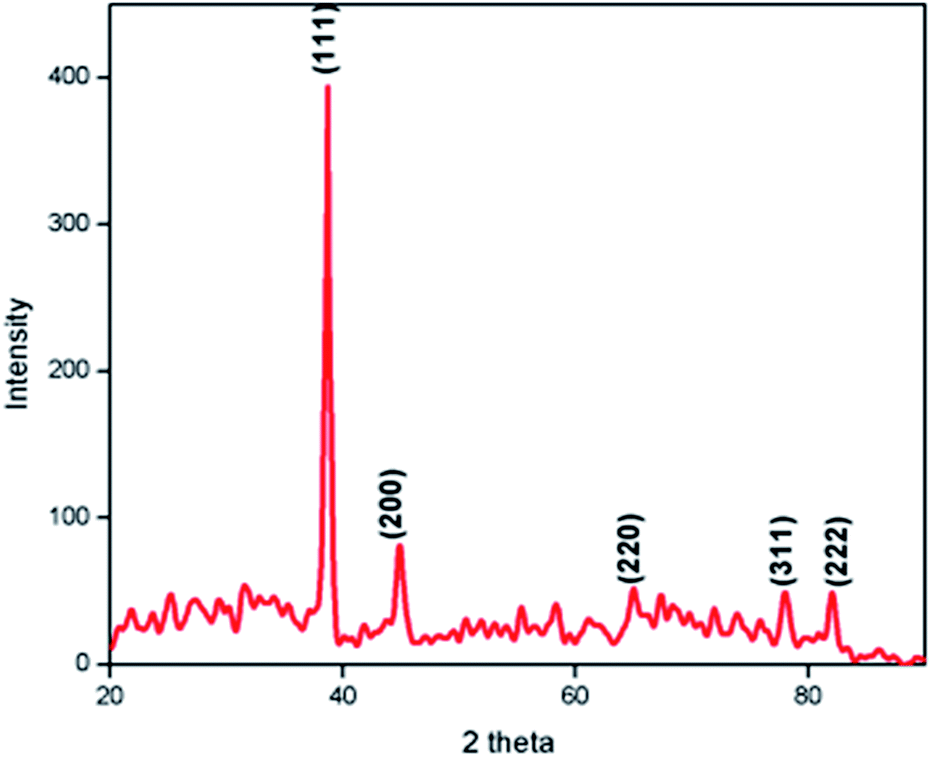
Fig. 2 shows the XRD pattern of the Ag@SiO2 nanospheres. All the diffraction peaks are found to be well matched with the standard JCPDS (PDF# 893722) data. No characteristic impurity peaks like Ag2O or AgO were detected. The strong and sharp diffraction peak observed at 38.627° for the corresponding plane (111) shows the face centered cubic structure of Ag nanoparticles and their crystalline nature. Due to its amorphous nature (see Fig. S1†), no diffraction peaks corresponding to SiO2 were observed.
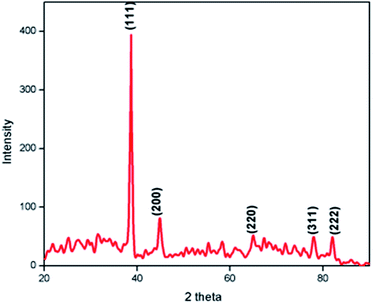 |
| | Fig. 2 XRD pattern of Ag@SiO2 nanospheres using hydrosol A. | |
From the SAED pattern of TEM analysis we confirmed that the prepared nanoparticles are polycrystalline. The calculated lattice constant values a = b = c = 4.0344 Å are consistent with the standard JCPDS data. Fig. 3(a and b) shows the XPS spectrum of Ag embedded silica which confirms the presence of metallic silver. The Ag 3d core level signals can be well fitted with the two peaks at binding energy values of 373.7 eV and 367.7 eV, corresponding to the Ag 3d3/2 and Ag 3d5/2 signals respectively. The XPS data substantiate that Ag nanospheres are self-assembled on the Si surface by Ag–Si chemical bonds.28 Also, the doublet peaks located at 367.7 and 373.7 eV can be assigned to Ag (0) according to a previous report.29 These results indicate that the oxidation state of Si in the Ag@SiO2 nanospheres is well sustained during the vertical growth deposition. So the LSPR that occurred between them could be confirmed for SERS intensity.
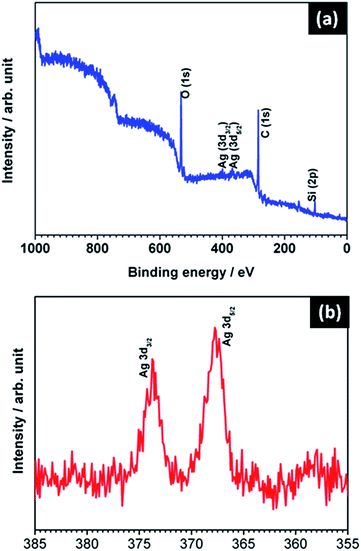 |
| | Fig. 3 (a) XPS spectra of Ag (hydrosol A) embedded SiO2 nanospheres (b) corresponding magnified spectra of Ag. | |
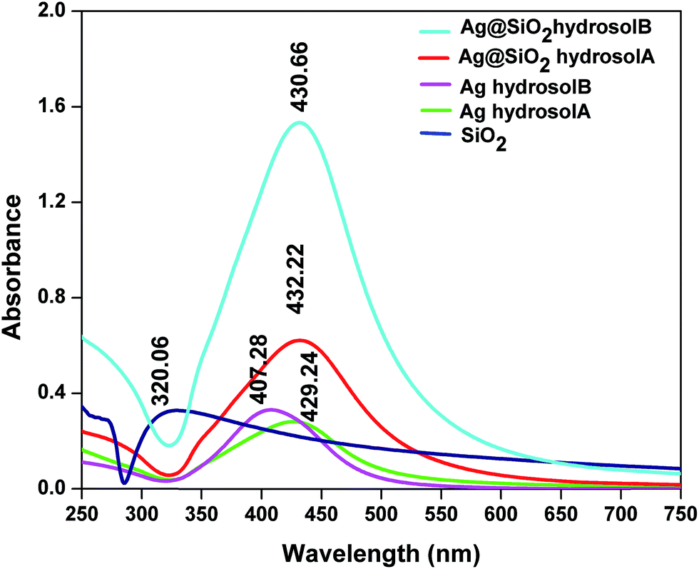
The prepared Ag and Ag@SiO2 nanostructured thin films were dispersed in ethanol and subjected to UV-Visible spectroscopy analysis. The reduction of Ag(I) to zero valent Ag nanoparticles was confirmed by the colour change of solution from colorless to yellow (Ag hydrosol A) and colorless to red (Ag hydrosol B)30 which correspond to absorption peaks at 429.24 and 407.28 nm respectively which are shown in Fig. 4. Ag nanoparticles exhibit surface plasmon resonances which are mostly sharp and well separated from interband transitions.
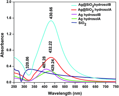 |
| | Fig. 4 Absorption spectra of Ag hydrosol and Ag@SiO2 nanospheres. | |
The red shift of the absorption wavelength and the broadening of the band for Ag hydrosol A are related to the larger particles. This is due to the dipole–dipole interaction among Ag nanoparticles deposited on the dielectric silica nanosphere and also electromagnetic coupling which enhances the polarizability of the electron cloud resulting in red shift of Surface Plasmon Resonance (SPR).31 The single and strong SPR bands indicate the formation of Ag nanoparticles through transverse and longitudinal resonances which are spherical in shape.32 The absorbance spectra of silica nanoparticles absorbed at 320 nm represent the specific peak for Si–O–Si bond which confirms the presence of silica nanoparticles. After the deposition of Ag nanoparticles onto the SiO2 spheres, broad and less intense peak appeared at 432.22 nm (SiO2 in Ag hydrosol A) and sharp and high intense peak appeared at 430.66 nm (SiO2 in Ag hydrosol B) due to the increase in the local refractive index of the surrounding medium for the Ag nanospheres caused by the formation of silica nanospheres and Mie Plasmon resonance excitation from the Ag nanoparticles.33 There is a slight red shift in absorption wavelength with increasing the size of the silver nanoparticles exhibiting stronger Plasmon resonance.34,35 The quantitative analysis of silver hydrosol A and B using SEM images Fig. 7(e and f) shows the size distribution of different silver nanoparticles. The normal curve function which show average size distribution of silver hydrosol A and B (see Fig. S3†). Thus in case of silver hydrosol B the increase in the intensity is due to participation of more no of particles for Surface Plasmon Resonance compare to silver hydrosol A. This elucidates a difference of 2 nm in the UV analysis for Ag@SiO2 A and B.
For the growth of silica, two main models have been emerged i.e. the ‘monomer addition model’ and the ‘aggregation growth model’. But still the debate is not over and new growth mechanisms have been postulated.36 Our findings conclude that growth occurs due to aggregation, where the primary particles with broad size distribution are generated in solution over a long time. The growth process of silica nanospheres were sequentially investigated using field emission scanning electron microscopy (see Fig. S2†).
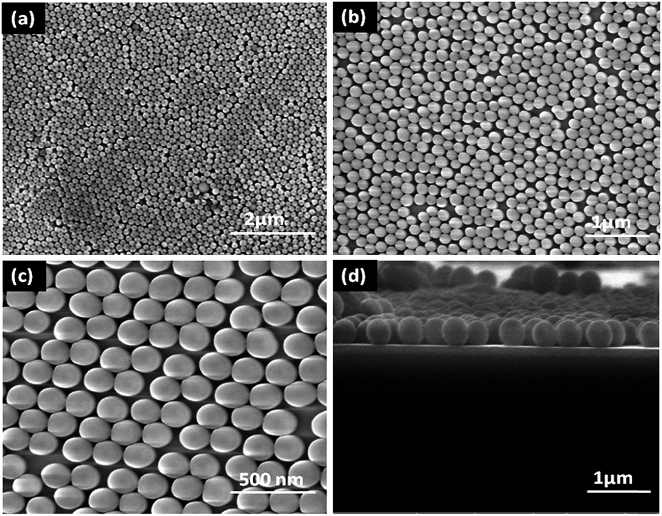
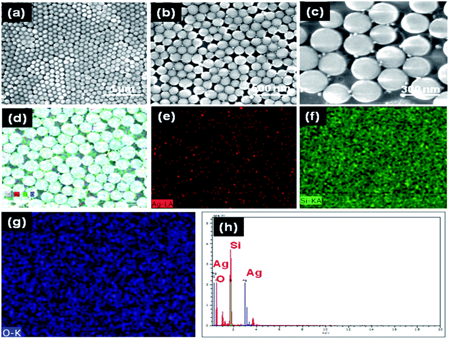
Growth process of SiO2 nanospheres is shown in Fig. 5. Island like structures with a size of 1–2 μm were formed through a proper combination of constituents (60 mL ethanol, 0.78 mL TEOS, and NH3, 8 pH) which was constantly stirred for 5 min. An agglomeration of silica beads (150–200 nm) was formed under the same conditions with the addition of 5 mL of distilled water. On increasing the water concentration (10 mL) and pH (10), self-assembled arrays of silica nanospheres (Fig. 6(a–c)) were formed. So, the water molecules lead to faster kinetics and promote the nucleation of silica. In addition to this, the presence of ammonia promotes the formation of spherical particles. The effect of solvent and the presence of ammonia are the promising factors for the formation of highly ordered monodispersed spheres.37,38
 |
| | Fig. 5 Growth mechanism of silver embedded silica nanospheres ((i) absence of H2O, (ii) 5 mL H2O, (iii) 10 mL H2O, (iv) 10 mL H2O + pH 10). | |
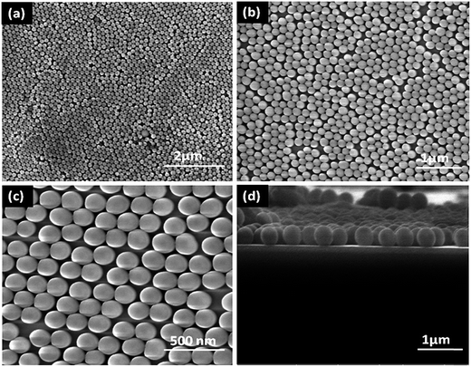 |
| | Fig. 6 (a–c) FESEM micrographs of SiO2 with different magnifications (d) cross section image of SiO2 nanospheres. | |
The proposed reaction mechanism is
| |
![[triple bond, length as m-dash]](https://www.rsc.org/images/entities/char_e002.gif) Si–OR + H2O → Si–OH + ROH Si–OR + H2O → Si–OH + ROH
| (1) |
| | |
Si–OR + Si–OH → Si–O–Si + ROH
| (2) |
here R represents ammonium hydroxide. When a glass slide is dipped into the colloidal solution and then pulled out, the liquid evaporates which pulls the nanospheres together to compact them into a densely-packed monolayer.
39 The monodispersity is also confirmed through the cross section image as shown in
Fig. 6(d). When the negatively charged glass substrate
40 reacts with the solution containing positive hydrogen ions, surface diffusion occurs, forming silanol groups. These silanol groups deprotonized the hydrogen ions and resulted in negatively charged silica nanospheres which is confirmed by zeta potential (see Fig. S6
†).
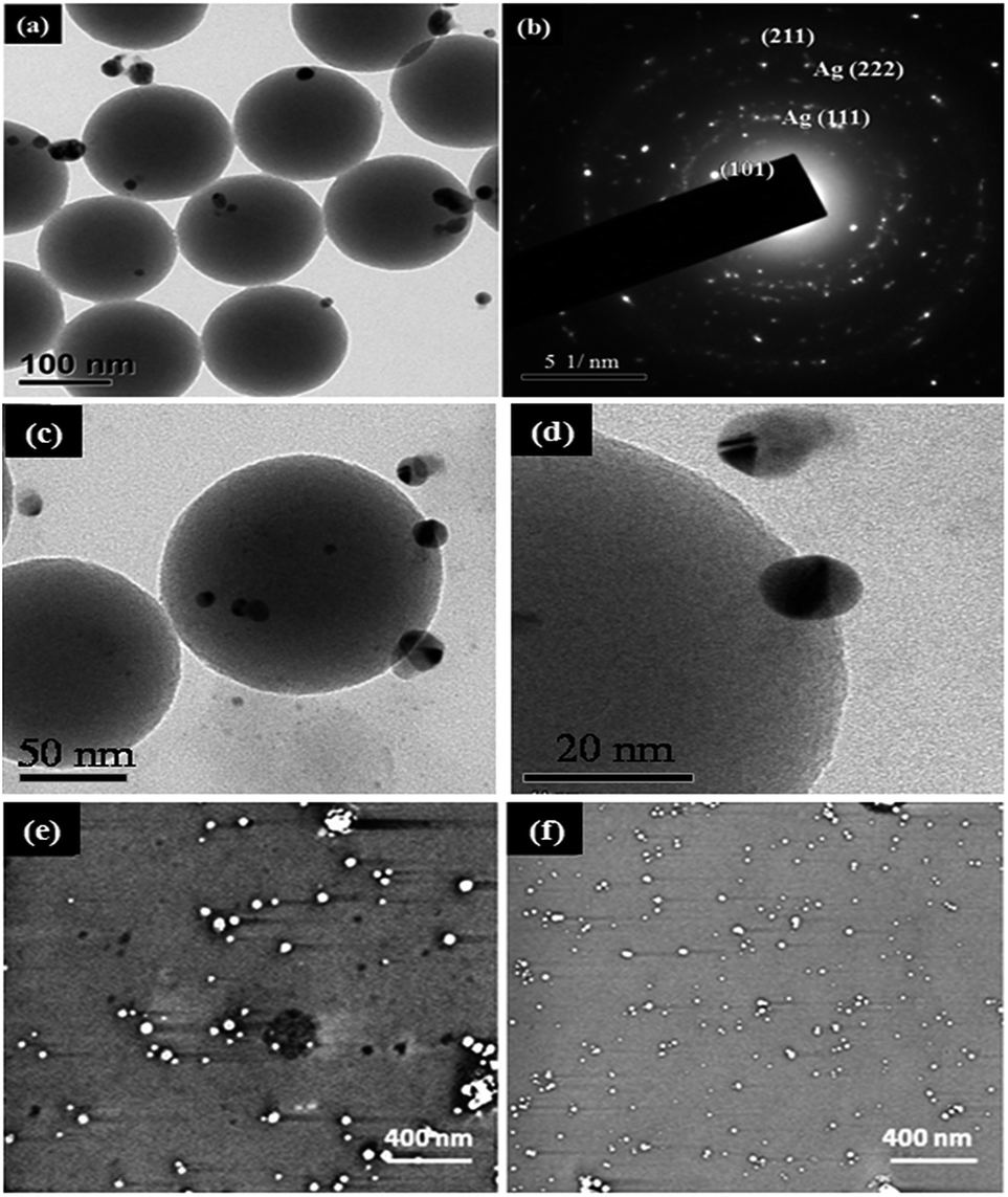
In our experiment, the Ag nanoparticles were deposited using two hydrosols as described in the experimental session. Fig. 7(a and b) shows HR-TEM image and its SAED pattern where the hkl value for the plane (111), (222) confirms face centered cubic structure of Ag nanoparticles which well matches with XRD. Also the attachments of AgNPs with SiO2 nanospheres show a gap of less than 5 nm as shown in Fig. 7(c and d). These give strong evidence of hot spots for SERS studies.
 |
| | Fig. 7 (a) HR TEM images of Ag@SiO2 nanospheres for silver hydrosol A (b) SAED pattern (c and d) magnified HRTEM images and FESEM micrographs of Ag nanospheres prepared using (e) hydrosol A (f) hydrosol B. | |
Ag films prepared from both hydrosols show that the Ag nanoparticles are isolated from each other with no aggregation and it is clear that the size of Ag nanoparticles obtained using hydrosol A is bigger than those with Ag hydrosol B. As seen in Fig. 7(e and f) the Ag nanospheres obtained using Ag hydrosol A and B were in the size ranges of 15–20 nm and 5–10 nm respectively. The high degree of super saturation of NaBH4 leads to the formation of smaller silver nanoparticles. The positively charged silver nanoparticles prepared from hydrosol B cling onto the surface of silica nanospheres due to the negative surface charge of silica (see Fig. S4–S7†). As shown in Fig. 8(a–c), the negatively charged silver nanoparticles (hydrosol A) assemble in the nanogap between silica nanoparticles which may be due to the capillary forces41 and in the present case, the silica nanospheres array can act as the channel. The surface charge of Ag nanoparticles was confirmed by zeta potential analysis (see Fig. S8†) and the relationship between interparticle gap and SERS activity for Ag nanoparticle shows a dramatic enhancement when the size is in between 15–20 nm.42–46 As a result, Ag@SiO2 nanospheres obtained using Ag hydrosol A are considered as promising SERS substrates owing to their unique morphology. The atomic percentages of Si (35.21 at%), O (53.14 at%) and Ag (11.65 at%) confirm the formation of Ag@SiO2 nanospheres (Fig. 8(h)) and color mapping shows the elemental analysis of Ag@SiO2 (Fig. 8(d–g)). The red dots indicate the Ag peaks while the green and blue dots indicate the silicon dioxide.
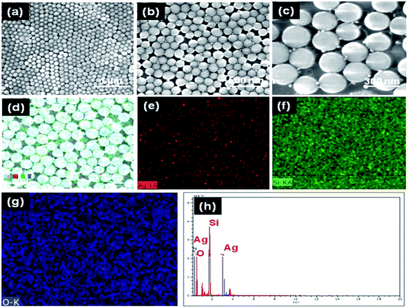 |
| | Fig. 8 (a–c) FESEM micrographs of Ag@SiO2 thin films with different magnifications (d–g) color mapping image of Ag@SiO2 nanospheres (h) EDAX spectra of Ag@SiO2 [note: here Ag represents hydrosol A]. | |
Roughness is one of the most important parameters for SERS. When the molecules are adsorbed to the metallic surfaces and exhibit atomic scale roughness, the Raman signal intensity is enhanced by 104 to 106 times. Fig. 9(a–e) represents the 2D and 3D images of SiO2 and Ag@SiO2 nanospheres which are identical with the FE-SEM images. Fig. 9(c and f) presents the two-dimensional histograms containing surface height values determined from the respective topographies. The obtained SiO2 and Ag@SiO2 nanospheres exhibited root-mean-square (RMS) roughness values of 14.9057 and 26.004 nm respectively and show high monodispersity of nanospheres.
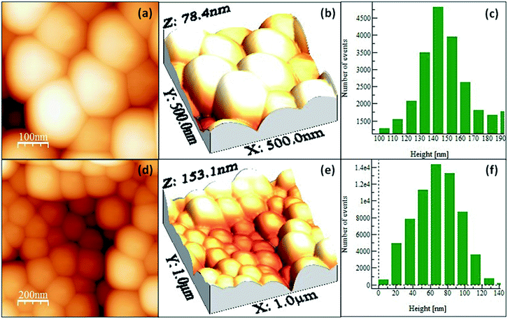 |
| | Fig. 9 AFM 2D and 3D images of (a and b) SiO2 nanospheres (d and e) Ag@SiO2 nanospheres and (c & f) histograms of SiO2 and Ag@SiO2 nanospheres [note: here Ag represents hydrosol A]. | |
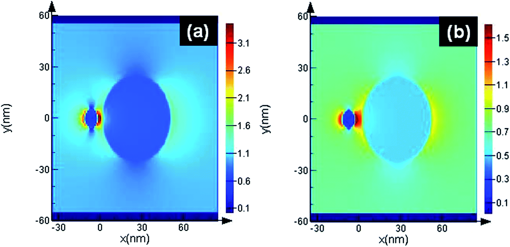
The finite-difference time-domain (FDTD) method is adopted using lumerical solution-8. Intensity (|E|2) distributions are obtained from 3D FDTD calculations based on the following parameters: SiO2 (glass) palik material has been used as material, where the diameter of noble metal nanoparticles was 20 nm and an interparticle gap of 5 and 2.5 nm between silica and silver was chosen. Laser with 514 nm wavelength was employed. The detailed process is illustrated in Fig. 10. The maximum intensity (|E|2) of each noble metal/semiconductor was 112. As the SERS signals were proportional to the value of (|E|2), the 20 nm silver nanoparticles give larger SERS enhancement. Similarly in Fig. 10(a), when the gap between silica and silver is around 2.5 nm the hot spots increase and give strong electric field enhancement, while in the case of Fig. 10(b), smaller electric field enhancement occurs around the spheres when the nano gap is around 5 nm compared to the gap of 2.5 nm. It means that hotspots are formed between the silica and silver nanospheres and giant SERS enhancement can be obtained.
 |
| | Fig. 10 Electric field (〈|E|〉2) distributions obtained from 3D FDTD calculations at wavelength 514 nm of (a) 2.5 nm gap (b) 5 nm gap. | |
3.2 SERS analysis of self-assembled Ag embedded silica thin films
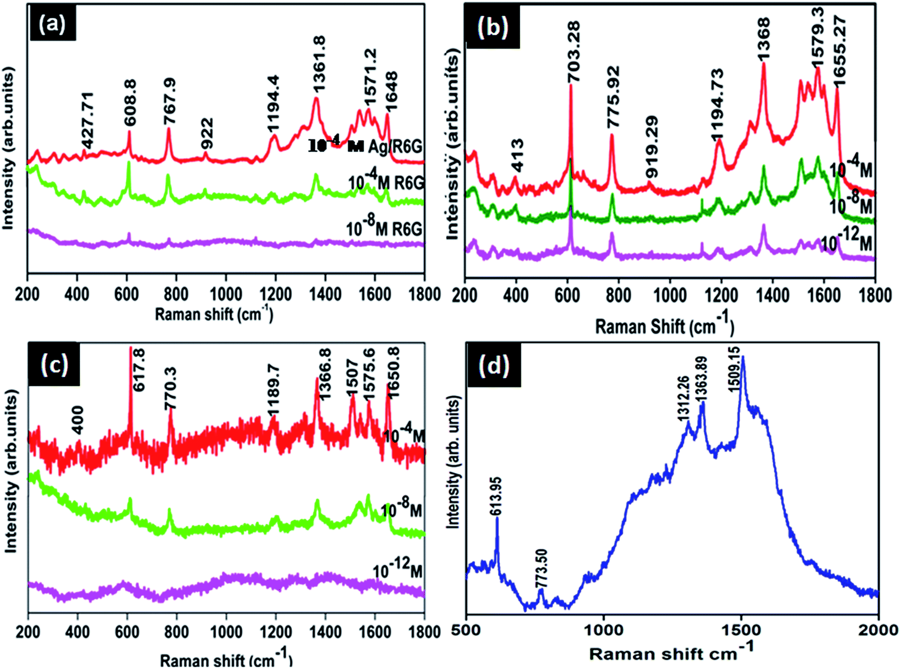
Fig. 11(b) and (c) show the SERS spectra of R6G with different molar ratios adsorbed on Ag@SiO2 substrates using Ag hydrosols A and B. Normal Raman Spectrum (NRS) of R6G (Fig. 11(a)) with a molar concentration of 10−4 M gets shifted to 612.28, 771, 919, 1194, and 1367 cm−1 while neighbouring peaks at 1527 and 1571.2 cm−1 merge into one broad peak at 1575 cm−1 as shown in Fig. 11(c). Also two brother peaks observed at 1355 and 1180 cm−1 shifted to 1367 and 1194 cm−1 respectively on using Ag hydrosol A. The shifting and broadening are due to the binding of chloride ions of R6G with Ag@SiO2 which provide active sites for Raman enhancement.10 Nanoscale gaps and sharp points in metal nanostructures are the primary features needed to produce the highest possible enhancement in Raman scattering. Here the interparticle gap between silica and Ag nanospheres is below 5 nm (Fig. 8(c)) which results in strong localized plasmon resonance and offers an opportunity to realize notable SERS enhancement in the case of Ag hydrosol A. Electric-field enhancement for Ag nanoparticles assembled on silica contains three types of nanoparticle arrangements, such as isolated nanoparticles, surface-plasma-coupled nanoparticles, and aggregated nanoparticles. Signal enhancement for Ag@SiO2 using hydrosol A is attributed due to the surface-plasma-coupled nanoparticles arrangement,17 since, the enhancement increases rapidly when the spacing between neighbouring nanoparticles reduces (see Fig. S4†).
 |
| | Fig. 11 (a) SERS spectra of Ag/R6G and normal Raman spectra of R6G with 10−4 M and 10−8 M (b) SERS spectra Ag@SiO2 nanospheres (Ag hydrosol A) (c) SERS spectra Ag@SiO2 nanospheres (Ag hydrosol B) (d) R6G 10−11 M SERS spectra for Ag@SiO2 nanospheres (Ag hydrosol A) using 632 nm laser wavelength. | |
In the case of Ag@SiO2 using Ag hydrosol B, no noticeable intensity was observed for 10−12 M and 10−8 M due to the aggregated arrangement of Ag nanoparticles on monodispersed silica nanospheres. Fig. 11(a) shows normal Raman spectra of R6G for 10−8 and 10−4 M and the same on using silver sol A, while Fig. 11(b) and (c) show the SERS spectra of Ag@SiO2 using Ag hydrosol A and Ag hydrosol B respectively, where the maximum SERS is obtained for hydrosol A only. The use of Rhodamine 6G as a SERS probe using a 532 nm laser has been greatly discouraged, given the actual signal is coming from the so-called SER(R)S.47 The Rhodamine 6G is also in resonance with the laser, For confirmation of SERS we have taken the SERS spectra of R6G 10−11 molar concentration using 632 nm laser wavelength in Fig. 11(d). A similar work by Kudelski et al.48 shows that SERS effect is “switched on” in measurements with the red excitation radiation and the resonance Raman effect for R6G molecules is “switched off”. However the intensity recorded by them is very low for R6G using Ag@SiO2. In our case the peaks are shifted to ±5 cm−1 comparing to 514 nm wavelength and gives a much more high intense peak for R6G 10−11 M.
Hence it is concluded that the size of the Ag nanoparticles and the interparticle gap between silica and Ag nanoparticles are the primary factors for SERS enhancement. The enhancement factor was also calculated according to equation.26
where
Isurf and
Ibulk are the integrated intensities of R6G molecules adsorbed on Ag@SiO
2 SERS substrate for 10–11 M and 10–3 M of R6G bulk, respectively.
Nsurf and
Nbulk are the corresponding numbers of R6G molecules adsorbed on the SERS substrate and in the bulk solution effectively illuminated by the laser beam, respectively.
Nbulk =
AhCbulkNA, where
A is the area of the laser focal spot,
h is the focal depth of the laser, and
h is 13 μm according to the work.
26 Cbulk is the concentration of R6G bulk solution, here
Cbulk = 10–3 M,
NA is the Avogadro constant
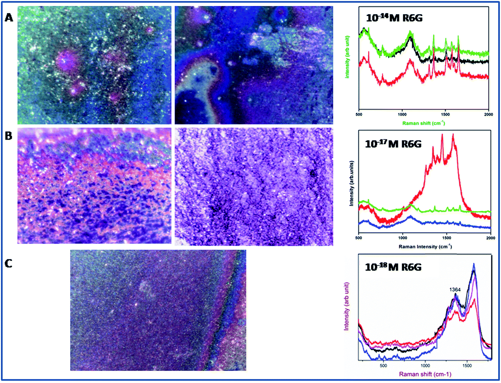
The above calculations (see Fig. S11†) were done for the 20 μl R6G solution (1 × 10⁻³ M) and the R6G – absorbed on Ag@SiO2 (1 × 10⁻¹¹ M, 20 μl) which were spread on the 1 × 1 cm2 prepare substrate. A laser spot area of 5 μm and power of (15 mW) was applied with an accumulation number of 1 s for all recordings. The Nbulk/Nsurf value is calculated to be 32.656 × 10⁵ and ISERS/Ibulk are about 7.79 for the vibration peak at 1367 cm−1 (see Fig. S11†). The EF value is calculated to be about 7.79 × 10⁸. Similarly we have also optimized the condition for lowest detection of 10−18 M based on their optical images as shown in the Fig. 12. In optical images we can easily able to identify the dye absorbance as shown in red color. The overall interpretation shows that when laser falls on red colored area we could expect enhanced Raman due to the linker molecule and charge transfer of dye into substrate. In case of 10−18 M the peaks were very weak but the spectra at 1367 cm−1 can be easily absorbed while the remaining peaks were shows very weak intensity. This confirms the contribution of highly monodispersed silica nanospheres for the SERS enhancement.
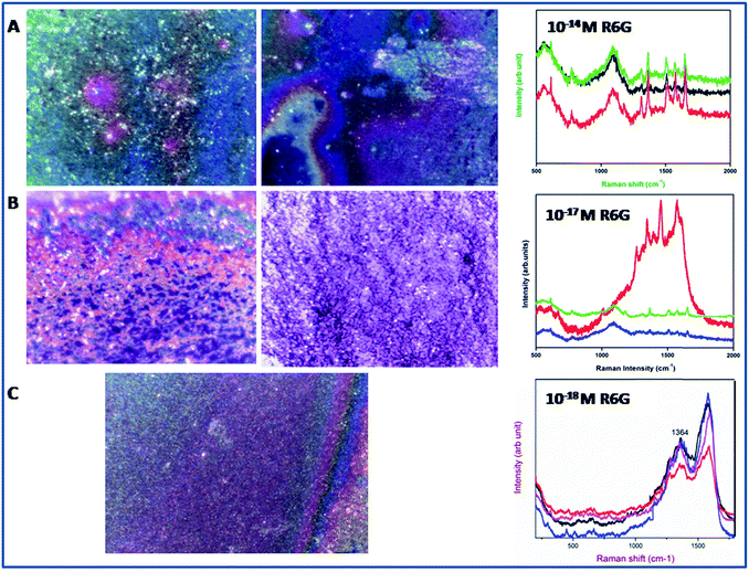 |
| | Fig. 12 Optical images of Ag@SiO2 nanospheres film using confocal Raman spectrometer (a) R6G 10−14 M (b) R6G 10−17 M (c) R6G 10−18 M. | |
The designed substrates show good reproducibility that is confirmed through FESEM images (see Fig. S9†). A previous study on nanowires42 shows the tendency to form clusters after drying the analyte solution. But in the present study the nanospheres shows no bundling and clustering. The results show the good stability of nanospheres against the analyte. A substrate of 1 × 1 cm was dispersed with R6G with a molar of 10−11 and spectra were recorded for 30 spots to check the reproducibility of film (Fig. 13). The substrate shows highly intense and uniform peak over the substrate. The stability of prepared colloid was checked over the different substrates and different period of time which confirms the consistency of solution and film Fig. 13(d and e). Fig. 13(d and e) represents the SERS spectra of R6G over ITO and silicon substrate. This confirms that the present method is different from other techniques where the nanogaps formation is not defined over the substrate. The Fig. 13(b) clearly shows that the silver prepared using hydrosol A with a size of 15 nm exactly cling in between silica nanospheres due to the low nanogap between two spheres, whereas the bigger particle are not able to adhere inside the obtained gap (see Fig. S1†). So this confirms that the nanogaps formation in our substrate leads to good efficiency and reproducibility towards development of ultrasensitive SERS substrate. An Ag@SiO2 nanosphere for SERS application has been extensively analyzed in the present study, and it has been shown that a simple vertical deposition can be used to generate reproducible SERS substrates. The present method is technically sound and shows perfect morphology and designing procedure for the creation of hot spots. Moreover this method is of very low cost and is reproducible compared to other methods as shown in the comparative study (Table 1).
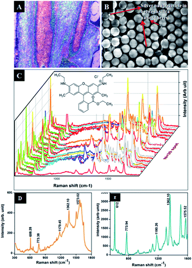 |
| | Fig. 13 (a) Optical image of Ag@SiO2 nanospheres film consist of R6G 10−11 M (optical image of 10−11 M R6G on Ag@SiO2 nanospheres film) (b) corresponding FE-SEM image (Ag@SiO2 nanospheres using Ag hydrosol A) (c) SERS spectra for 30 spots and chemical structure of R6G (d) SERS spectra of R6G for 10−11 M on ITO and (e) silicon substrate. | |
Table 1 Comparative SERS performance on Ag@SiO2 nanostructures
| Substrate |
Dye used and detection limit |
Enhancement factor |
Experimental method |
Optical quality and remarks |
Arrangement of silver over silica and its nanostructures |
Ref. |
| Silica nanoparticles |
R6G up to 10−5 M |
1.09 × 10⁶ |
Spin coating and vacuum deposition |
Fair |
Silver on monolayer silica. Structure not defined |
20 |
| Polycrystal structure with low detection limit |
| n-Type porous silicon nanostructures |
R6G up to 10−10 M |
— |
Colloidal method |
Poor |
Randomly arranged Ag nanoclusters in porous silicon |
22 |
| Difficulty in arrangement of pore diameter. Hot spots decrease while porosity increases |
| Boron-doped single crystal silicon (sc-Si) wafers |
R6G up to 10−15 M |
— |
Hydrothermal etching method |
Fair |
Ag/Si nanopillar like structure |
23 |
| Silver agglomeration and interfacial strain. No confirmation of hotspots |
| Silica colloidal microspheres |
R6G up to 10−12 M |
1.68 × 10⁷ |
Colloidal method |
Poor |
Silica colloidal microspheres with silver |
24 |
| Aggregated silver around silica and no proof for hot spots |
| Silica wafer |
R6G up to 10−18 M |
1016 |
Modified colloidal |
Fair |
Ag nanocontacts onto silica |
25 |
| Uniform sphere with agglomerated silver arrangement and no hot spots |
| Ag@SiO2 nanospheres glass substrate |
R6G up to 10−18 M |
7.79 × 10⁸ |
Vertical deposition (dip coating) |
Excellent |
Silver embedded silica nanospheres |
Present Work |
| Highly monodispersed spheres with maximum hot spots |
For the confirmation of SERS we have chosen another probe molecule melamine. Melamine is an organic chemical material and is mainly used to produce melamine-formaldehyde resins for glues, adhesives, and plastics. For boosting of protein content it has been used in dairy products such as milk.49 The present substrate shows the detection of melamine in liquid up to 10−8 molar concentration as shown in Fig. 14. Fig. 14 represents the SERS spectra of melamine in liquid for increasing concentration up to 10−8 M on to Ag@SiO2 substrate. The most prominent peak at 682 cm−1 is assigned to the ring breathing mode II and involves in-plane deformation of the triazine ring in melamine molecules.24
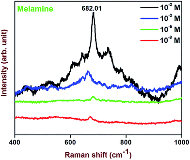 |
| | Fig. 14 SERS spectra of melamine enhanced by Ag@SiO2 (Ag hydrosol A) film for different molar concentrations. | |
4. Conclusion
Despite significant progresses in the field of plasmonic, it seems that SERS-active substrates with unique morphology, uniformity, stability, reproducibility and high enhancement factor are rather difficult to achieve. The technique used in the present study facilitates the fabrication of active SERS substrates consisting of highly monodispersed silica nanospheres array and with an ideal reproducible surface morphology where strong SERS signals can be generated from minimal quantities of adsorbed analyte. This method has the potential for application in SERS micro-detection devices. The ratio of ammonia to water was a key factor for the formation of self assembled nanospheres array. Adsorption behavior of R6G on Ag@SiO2 nanospheres, particle size of Ag nanospheres and interparticle gap between Ag@SiO2 nanospheres play important role in the fabrication of highly active surface enhanced Raman scattering substrates. It is also found that the SERS effect from noble metal and metal oxide films has its own limits whereas metal embedded metal oxide films show very high enhancement compared to ordinary ones. The electric field signal enhancement (hotspots) was confirmed through FDTD model. Ag@SiO2 substrates show good response to probe molecule R6G. Also it has been used as inspecting device for detection of trace chemical like melamine which is harmful to the environment. This simple and ultrasensitive substrate shows us the importance of nanostructures and their nanogaps arrangement within substrate. The substrate could be further used as a Raman reporter for early diagnosis of cancer and biosensor studies.
Acknowledgements
The authors want to thank Dr Joydeep Chowdhury and Sannak Dutta Roy, Chemical physics and materials science research group, Sammilani Mahavidyalaya, University of Kolkata for FDTD simulation.
References
- J. J. Giner-Casares and L. M. Liz-Marzán, Nano Today, 2014, 9, 365 CrossRef CAS PubMed.
- S. Bhavya, R. F. Renee, I. H. Anne, R. Emilie and R. P. Van Duyne, Mater. Today, 2012, 15, 16 CrossRef.
- M. Fleischmann, P. J. Hendra and A. J. McMullan, Chem. Phys, 1974, 26, 163 CAS.
- G. Xiao, B. Ying, Q. Chao and J. Chaoyang, Chem. Commun., 2012, 48, 7003 RSC.
- J. C. Richard and J. T. Martin, J. Raman Spectrosc., 2008, 39, 1313 CrossRef PubMed.
- Y. Zao, X. Xibin, L. Xibo, L. Jiangshan, W. Weidong, T. Yongjian and Y. Yougen, Appl. Surf. Sci., 2011, 258, 212 CrossRef PubMed.
- H. Hwang, S. Kim and Y. S. Man, Lab on a Chip, 2011, 11, 87 RSC.
- G. Kumari and C. Narayana, J. Phys. Chem. Lett., 2012, 3, 1130 CrossRef CAS.
- G. Sun and G. Grundmeier, Thin Solid Films, 2006, 515, 126 CrossRef PubMed.
- Y. Kobayashi, H. Katakami, E. Mine, D. Nagao, M. Konno and L. M. L. Marzan, J. Colloid Interface Sci., 2005, 283, 392 CrossRef CAS PubMed.
- M. C. Wu, M. P. Lin, S. W. Chen, P. H. Lee, J. H. Li and W. F. Su, RSC Adv., 2014, 4, 10043 RSC.
- Y. Yang, Z. Y. Li, K. Yamaguchi, M. Tanemura, Z. Huang, D. Jiang, Y. Chen, F. Zhou and M. Nogami, Nanoscale, 2012, 4, 2663 RSC.
- Z. Jiang and C. Liu, J. Phys. Chem. B, 2003, 107, 12411 CrossRef CAS.
- Y. Liu, Y. Zhang, H. Ding, S. Xu, M. Li, F. Kong, Y. Luo and G. Li, J. Mater. Chem. A, 2013, 1, 3362 CAS.
- V. E. Subramanian, E. Wolf and P. V. Kamat, J. Phys. Chem. B, 2001, 105, 11439 CrossRef CAS.
- X. Q. Wang, T. J. He, H. Wen, C. Y. Xu, J. Zuo and F. C. Liu, Spectrochim. Acta, Part A, 1997, 53, 2495 CrossRef.
- R. Xu, W. Xiao-Dong, W. Liu, X. Xiao-Na, L. Yue-Qiang and A. Ji, Chin. Phys. B, 2012, 2, 025202 CrossRef.
- L. Shijia, L. Li, G. Hao, Y. Wu and L. Feng, Dyes Pigm., 2012, 95, 473 CrossRef PubMed.
- B. Li-Li, M. M. Shannon, L. Cheng-Du and D. Sheng, J. Raman Spectrosc., 2003, 34, 394 CrossRef PubMed.
- F. G. Kirsty and A. P. Girard, J. Phys. Chem. C, 2010, 114, 22406 Search PubMed.
- W. Ming-Chung, L. Min-Ping, C. Shih-Wen, L. Pei-Huan, L. Jia-Han and S. Wei-Fang, RSC Adv., 2014, 4, 10043 RSC.
- A. Y. Panarian, S. N. Terekhov, K. I. Kholostov and V. P. Bondaren Ko, Appl. Surf. Sci., 2010, 256, 6969 CrossRef PubMed.
- Y. Q. Wang, S. Ma, Q. Q. Yang and X. J. Li, Appl. Surf. Sci., 2012, 258, 5881 CrossRef CAS PubMed.
- K. W. X. Zhang, C. Niu and Y. Wang, ACS Appl. Mater. Interfaces, 2014, 6, 1272 Search PubMed.
- Y. Han, S. Liu, B. Liu, C. Jiang and Z. Zhang, RSC. Adv., 2014, 4, 2776 RSC.
- J. Chen, G. Qin, W. Shen, Y. Li and B. Das, J. Mater. Chem. C, 2015, 3, 1309 RSC.
- P. Suresh, J. Sundaramurthy, D. Mangalaraj, D. Nataraj, D. Rajarathnam and M. P. Srinivasan, J. Colloid Interface Sci., 2011, 363, 51 Search PubMed.
- Y. W. Lu, X. W. Du, J. Sun and X. Han, J. Appl. Phys., 2006, 100, 063512 CrossRef PubMed.
- L. Kai, J. Xiaotong, T. Aiwei, Z. Xibin, M. Huan and W. Yingfeng, Integr. Ferroelectr., 2012, 136, 9 CrossRef PubMed.
- K. Wang, X. Zhang, C. Niu and Y. Wang, ACS Appl. Mater. Interfaces, 2014, 6, 1272 CAS.
- G. Upender, R. Sathyavathi, B. Raju, C. Bansal and R. Narayana, J. Mol. Struct, 2012, 1012, 56 CrossRef CAS PubMed.
- S. Werner, F. Arthur and B. Ernst, J. Colloid Interface Sci., 1968, 26, 62 CrossRef.
- O. Keng-Liang, H. Ting-Chu, L. Yu-Chuan and Y. Kuang-Hsuan, Mater. Chem. Phys., 2012, 135, 892 CrossRef PubMed.
- K. Nogi, M. Naito and T. Okoyamal, Nanoparticle Technology-Handbook, 2012 Search PubMed.
- R. Tzounis, C. Caceres, L. Schellkopf, D. Jehnichen, D. Fischer, C. Cai, P. Uhlmann and M. Stamm, RSC Adv., 2014, 4, 17846 RSC.
- C. C. M. C. Carcouët, M. W. P. Van de Put, B. Mezari, P. C. M. M. Magusin, J. Laven, P. H. H. Bomans, H. Friedrich, A. C. C. Esteves, N. A. J. M. Sommerdijk, R. A. T. M. van Benthem and G. deWith, Nano Lett., 2014, 14, 1433 CrossRef PubMed.
- R. Kota Sreenivasa, K. El-hami, K. Tsutomu, M. Kazumi and M. Keisuke, J. Colloid Interface Sci., 2005, 289, 125 CrossRef PubMed.
- G. Schatz, Acta Phys. Pol., A, 2009, 115, 431 CAS.
- I. Hyungsoon, C. B. Kyle, C. L. Nathan, L. H. Christy and H. Sang-Hyun, Nano Lett., 2010, 10, 2231 CrossRef PubMed.
- W. L. W. Hau, D. W. Trau, N. J. Sucher, M. Wong and Y. Zohar, J. Micromech. Microeng., 2003, 13, 272 CrossRef CAS.
- S. H. Im, Y. T. Lim, D. J. Suh and O. O. Park, Adv. Mater., 2002, 19, 1367 CrossRef.
- J. B. Jackson and N. J. Halas, J. Phys. Chem. B, 2001, 105, 2743 CrossRef CAS.
- K. G. Stamplecoskie and J. C. Scaiano, J. Phys. Chem. C, 2011, 115, 1403 CAS.
- S. L. Kleinman, R. R. Frontiera, A. I. Henry, J. A. Dieringer and R. P. Van Duyne, Phys. Chem. Chem. Phys., 2013, 15, 21 RSC.
- H. H. Wang, C. Y. Liu, S. B. Wu, N. W. Liu, C. Y. Peng, T. H. Chan, C. F. Hsu, J. K. Wang and Y. L. Wang, Adv. Mater, 2006, 18, 491 CrossRef CAS PubMed.
- J. N. Chen, T. Martensson, K. A. Dick, K. Deppert, H. Q. Xu, L. Samuelson and H. X. Xu, Nanotechnology, 2008, 19, 275712 CrossRef PubMed.
- M. Moskovits, Phys. Chem. Chem. Phys., 2013, 15, 5301 RSC.
- A. Kudelski and S. Wojtysiak, J. Phys. Chem. C, 2012, 116, 16167 CAS.
- J. M. Li, W. F. Ma, C. Wei, L. J. You, J. Guo, J. Hu and C. C. Wang, Langmuir, 2011, 27, 14539 CrossRef CAS PubMed.
Footnote |
| † Electronic supplementary information (ESI) available. See DOI: 10.1039/c5ra04355g |
|
| This journal is © The Royal Society of Chemistry 2015 |
Click here to see how this site uses Cookies. View our privacy policy here.