Superhydrophobic and superoleophilic hybrid foam of graphene and carbon nanotube for selective removal of oils or organic solvents from the surface of water
Xiaochen
Dong†
a,
Jun
Chen†
b,
Yanwen
Ma
b,
Jing
Wang
a,
Mary B.
Chan-Park
a,
Xiangmei
Liu
b,
Lianhui
Wang
b,
Wei
Huang
b and
Peng
Chen
*a
aDivision of Bioengineering, School of Chemical and Biomedical Engineering, Nanyang Technological University, 70 Nanyang Drive, 637457, Singapore. E-mail: ChenPeng@ntu.edu.sg; Fax: +65 6791 1761; Tel: +65 6514 1086
bKey Laboratory for Organic Electronics & Information Displays (KLOEID), Institute of Advanced Materials (IAM), Nanjing University of Posts and Telecommunications (NUPT), 9 Wenyuan Road, Nanjing, 210046, China
First published on 11th September 2012
Abstract
A monolithic 3D hybrid of graphene and carbon nanotube was synthesized by two-step chemical vapor deposition. Owing to its superhydrophobic and superoleophilic properties, it can selectively remove oils and organic solvents from water with high absorption capacity and good recyclability.
With the increasing awareness of environmental protection and need for water recycling, it is imperative to develop novel materials that are able to effectively absorb, remove, and transfer oil spills or organic contaminants from the surface of water. Oil sorbent materials have been developed from cross-linked co-polymers,1,2 organic or inorganic nanowire films,3,4 macroporous nanocomposites,5,6 carbon nanotube sponges7,8 and carbon nanotube modified polymer coating,9etc. These materials, however, exhibit some drawbacks compared to the ideal absorbers which should exhibit superhydrophobicity and superoleophilicity, low density, high oil sorption capacity, low water pickup, low-cost, environmental friendliness, and good recyclability.
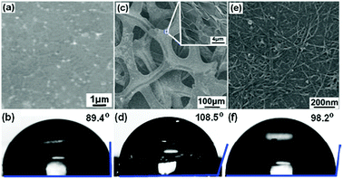
Graphene, a single-atom-thick carbon sheet, has recently attracted tremendous interests in many fields (e.g., nanoelectronics,10 sensors,11,12 energy devices13,14) due to its extraordinary electrical, physical, chemical, mechanical, and structural properties.15,16 Its hydrophobic property implies its potential in oil absorption. We measured the contact angle of a graphene film grown by chemical vapor deposition (CVD). The large contact angle (θc = 89.4°, measured with a FTA200 Dynamic Contact Angle Analyzer) clearly indicates its hydrophobicity (Fig. 1a and b). The two dimensional (2D) graphene film, however, is not a superhydrophobic material (θc = 150° by definition). Three dimensional (3D) porous structures are desired to absorb and retain oils or organics with large capacity. Recently, 3D foam of chemically derived graphene (CDG) has been synthesized and used for oil adsorption.17 But its adsorption capacity is moderate, due to the compromised hydrophobicity of CDG (as compared with defect-free CVD graphene) and the too-small and non-uniform pore structure.
 | ||
| Fig. 1 SEM images, and optical images of a water droplet placed onto the surface, of a 2D graphene film (a, b), 3D graphene foam (c, d) and a 2D CNT network film (e, f). The inset of (c) shows the SEM image of the graphene skeleton surface. | ||
A 3D monolith of CVD graphene has recently been demonstrated.18 As described previously, 3D graphene is CVD-grown using nickel foam as the substrate and ethanol as the carbon source; nickel foam can be subsequently removed by HCl leaving 3D graphene free-standing.19 The obtained monolith is macroporous (100–200 μm) and is an extremely thin (thus lightweight) scaffold consisting of only single or few-layer graphene domains (Fig. 1c). Intuitively, the uniform, monolithic, macroporous structure of such 3D graphene is ideal for oil adsorption, retention, and transfer. As shown in Fig. 1d, the θc value of 3D graphene is 108.5°. The improved hydrophobicity compared to 2D graphene is because of the underneath air pockets trapped in the porous graphene structure, as formulated by the Cassie–Baxter surface model.20,21 It, however, is still not superhydrophobic.
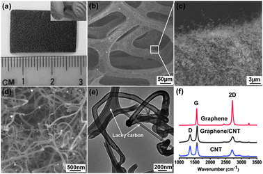
It is known that the intrinsic hydrophobicity can be enhanced by surface roughness. Based on this idea, carbon nanotube (CNT) networks have been used to increase the surface hydrophobicity taking advantage of the high hydrophobic property of CNT (the 1D cousin of 2D graphene) and the nano-texture of its network.22 As shown in Fig. 1e and f, the contact angle of the 2D CNT network thin-film is larger than the smooth graphene film. Prompted by this, we devised a two-step CVD process to synthesize 3D graphene–CNT hybrid foam. Briefly, after growing graphene on nickel (Ni) foam, the graphene–Ni substrate is immersed into 10% (w/w) polyethylene glycol ethanol solution containing 0.1 mM Ni(NO3)2 as the precursor of the CNT growth catalyst (Ni particle) for about 2 min and dried in air. Using ethanol as the carbon source, CNTs are CVD-grown at 750 °C for 40 min. Finally, Ni foam was etched away with 3 M HCl at 80 °C overnight to obtain 3D graphene–CNT hybrid foam (Fig. 2a). The bulk density of the resulting graphene–CNT hybrid foam is about 6.92 mg cm−3 and the hybrid can be reversibly bent with a large angle (Fig. 2a, inset).
 | ||
| Fig. 2 (a) Optical image of graphene–CNT hybrid foam. Inset shows the bent hybrid. (b, c, d) SEM images of graphene–CNT hybrid foam with different magnifications. (e) TEM image of individual CNT. (f) Typical Raman spectra of bare graphene foam, graphene–CNT hybrid foam and pure CNTs. | ||
As revealed by scanning electron microscopy (SEM), a dense forest of carbon nanotubes fully and uniformly wraps around the 3D graphene scaffold (Fig. 2b–d). This porous hybrid carbon foam is distinct to the previously reported vertically-grown high-density CNTs on a 2D graphene film.23 Transmission electron microscopy (TEM) shows that CNTs are multi-walled with an outer diameter of ∼100 nm (Fig. 2e). A typical Raman spectrum of bare 3D graphene is presented in Fig. 2f (top); the intensity ratio between the characteristic 2D and G band indicates that the region of measurement is a single graphene layer.24 There is no obvious defect band at ∼1350 cm−1 indicating high quality of the graphene foam. The Raman spectrum of the 3D graphene–CNT hybrid (Fig. 2f, middle) exhibits characteristic peaks of multi-walled CNTs (Fig. 2f, bottom),25 indicating the full coverage by CNTs. Compared to the solution-based self-assembly of chemically modified graphene or CNT,26,27 the CVD approach ensures seamless integration of graphene and CNT, preservation of their pristine properties, and realization of the well-defined monolithic 3D structure.
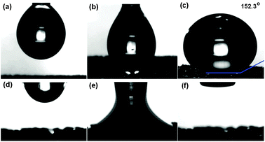
Fig. 3a–c demonstrates the wetting behavior of a water droplet on the surface of a graphene–CNT hybrid. As shown, the water droplet assumes a large contact angle of 152.3°, indicating that the hybrid is superhydrophobic. Such superior hydrophobicity of the 3D graphene–CNT hybrid as compared with 2D graphene, 2D CNT network, and bare 3D graphene is due to the nano-roughness created by the CNT forest on the graphene surface and the air interfaces in the macroscopic voids of the 3D structure and the nanoscopic voids in the CNT forest. In contrast, the droplet of compressor oil quickly spreads and is then completely sucked into the hybrid carbon foam (Fig. 3d–f). Clearly, the hybrid carbon foam is superoleophilic (perfect oil-wetting as evidenced by θc = 0°).
 | ||
| Fig. 3 Video snapshots of the wetting behaviour of a water droplet (a, b, c) and a compressor oil droplet (d, e, f) placed onto the surface of a graphene–CNT hybrid foam. | ||
As shown in Fig. 4, when brought into contact with a drop of toluene floating on the surface of water, toluene is immediately and completely adsorbed into the free-standing graphene–CNT hybrid. This clearly suggests the potential use of the 3D graphene–CNT hybrid as the selective absorbent to remove oils and organic solvents from water. To further demonstrate this, we investigated the absorption capacities (κ) of the graphene–CNT hybrid foams for several kinds of oils and organic solvents including compressor oil, sesame oil, chloroform, dichlorobenzene, toluene and dimethylformamide (DMF). The absorption capacity is defined as κ = (weight after saturated adsorption − initial weight)/initial weight.
 | ||
| Fig. 4 Removing a toluene droplet (labelled with oil blue N dye) from the surface of water using the graphene–CNT hybrid foam. | ||
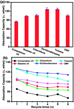
As shown in Fig. 5, the adsorption capacity of the hybrid carbon foam ranges from ∼80 to ∼130. This is significantly superior to oil absorption resins,28 3D macroporous nanocomposites,5 and inorganic nanowire membranes.4 The adsorption capacity depends not only on the density but also viscosity and surface tension. For example, although chloroform has a higher density than toluene (1.49 vs. 0.87 g cm−3), its adsorption by the graphene–CNT foam is poorer. This can be explained by the higher viscosity (0.56 vs. 0.45 cSt) and lower surface tension (0.027 vs. 0.029 γ/N m−1) of chloroform than that of toluene. The adsorption capacity of the hybrid foam is better than the bare 3D graphene (κdichlorobenzene ≈ 71.2 and κcompressor oil ≈ 48.5), indicating the important role of CNT forests. More importantly, the absorbed oil can be removed by washing with acetone followed by drying at 140 °C, while absorbed organic solvents can be simply removed by drying at 140 °C. In this way, the hybrid foam can be re-used multiple times without significant loss in adsorption capacity (Fig. 5b). The recyclability of this macroporous foam is much better than the nanoporous CNT sponges.7,8
 | ||
| Fig. 5 (a) Oil and organic solvent absorption capacities of the graphene–CNT hybrid foams. The error bars indicate the standard deviations from 3 samples. (b) Absorption recyclability of the graphene–CNT hybrid foams for oils and organic solvents. | ||
In summary, we have presented a simple CVD method to synthesize a novel 3D graphene–CNT hybrid. The 3D graphene serves as the ultra-light 3D scaffold to anchor the CNT forest. The all-carbon hybrid foam exhibits superhydrophobic properties owing to its bulk porous structure, surface nano-roughness and nanoscopic voids, and the hydrophobicity of CNTs. We show that the hybrid foam can be used to selectively remove oils and organic solvents from the surface of water with high capacity owing to its superoleophilicity and the macroporous structure that can effectively retain the absorbates. This study exemplifies the synergistic integration between the 2D graphene and 1D CNT for novel applications.29–31 Furthermore, the demonstrated 3D carbon foam shall also warrant other novel applications, e.g., serving as a 3D electrode in energy storage or conversion devices.
This work was supported by National Research Foundation of Singapore (NRF-CRP-07-2), Ministry of Education of Singapore (AcRF tier 2, MOE2011-T2-2-010), NNSF of China (50902071, 61076067, 20903057, 61006007, 21275076), the Key Project of Chinese Ministry of Education (212058), Jiangsu Province Science Foundation for Six Great Talent Peak (RLD201103).
Notes and references
- G. R. Shan, P. Y. Xu, Z. X. Weng and Z. M. Huang, J. Appl. Polym. Sci., 2003, 90, 3945 CrossRef CAS.
- X. M. Zhou and C. Z. Chuai, J. Appl. Polym. Sci., 2010, 115, 3321 CrossRef CAS.
- J. Wu, N. Wang, L. Wang, H. Dong, Y. Zhao and L. Jiang, ACS Appl. Mater. Interfaces, 2012, 4, 3207 CAS.
- J. Yuan, X. Liu, O. Akbulut, J. Hu, S. L. Suib, J. Kong and F. Stellacci, Nat. Nanotechnol., 2008, 3, 332 CrossRef CAS.
- Y. Chu and Q. Pan, ACS Appl. Mater. Interfaces, 2012, 4, 2420 CAS.
- D. D. Nguyen, N. H. Tai, S. B. Lee and W. S. Kuo, Energy Environ. Sci., 2012, 5, 7908 CAS.
- X. C. Gui, H. B. Li, K. L. Wang, J. Q. Wei, Y. Jia, Z. Li, L. L. Fan, A. Y. Cao, H. W. Zhu and D. H. Wu, Acta Mater., 2011, 59, 4798 CrossRef CAS.
- X. C. Gui, J. Q. Wei, K. L. Wang, A. Y. Cao, H. W. Zhu, Y. Jia, Q. K. Shu and D. H. Wu, Adv. Mater., 2010, 22, 617 CrossRef CAS.
- H. J. Song, S. Q. Shen and S. F. Meng, J. Dispersion Sci. Technol., 2010, 31, 1465 CrossRef CAS.
- F. N. Xia, D. B. Farmer, Y. M. Lin and P. Avouris, Nano Lett., 2010, 10, 715 CrossRef CAS.
- Y. X. Liu, X. C. Dong and P. Chen, Chem. Soc. Rev., 2012, 41, 2283 RSC.
- Y. X. Huang, X. C. Dong, Y. X. Liu, L. J. Li and P. Chen, J. Mater. Chem., 2011, 21, 12358 RSC.
- X. C. Dong, H. Xu, X. W. Wang, Y. X. Huang, M. B. Chan-Park, H. Zhang, L. H. Wang, W. Huang and P. Chen, ACS Nano, 2012, 6, 3206 CrossRef CAS.
- N. G. Sahoo, Y. Pan, L. Li and S. H. Chan, Adv. Mater., 2012, 24, 4203 CrossRef CAS.
- D. C. Wei and Y. Q. Liu, Adv. Mater., 2010, 22, 3225 CrossRef CAS.
- G. Eda and M. Chhowalla, Adv. Mater., 2010, 22, 2392 CrossRef CAS.
- Z. Niu, J. Chen, H. H. Hng, J. Ma and X. Chen, Adv. Mater., 2012, 24, 4144 CrossRef CAS.
- Z. P. Chen, W. C. Ren, L. B. Gao, B. L. Liu, S. F. Pei and H. M. Cheng, Nat. Mater., 2011, 10, 424 CrossRef CAS.
- Y. C. Yong, X. C. Dong, M. B. Chan-Park, H. Song and P. Chen, ACS Nano, 2012, 6, 2394 CrossRef CAS.
- A. Marmur, Langmuir, 2003, 19, 8343 CrossRef CAS.
- I. A. Larmour, S. E. J. Bell and G. C. Saunders, Angew. Chem., Int. Ed., 2007, 46, 1710 CrossRef CAS.
- F. C. C. Moura and R. M. Lago, Appl. Catal., B, 2009, 90, 436 CrossRef CAS.
- D. H. Lee, J. E. Kim, T. H. Han, J. W. Hwang, S. Jeon, S. Choi, S. H. Hong, W. J. Lee, R. S. Ruoff and S. O. Kim, Adv. Mater., 2010, 22, 1247 CrossRef CAS.
- D. Graf, F. Molitor, K. Ensslin, C. Stampfer, A. Jungen, C. Hierold and L. Wirtz, Nano Lett., 2007, 7, 238 CrossRef CAS.
- X. C. Dong, B. Li, A. Wei, X. H. Cao, M. B. Chan-Park, H. Zhang, L. J. Li, W. Huang and P. Chen, Carbon, 2011, 49, 2944 CrossRef CAS.
- S. H. Lee, H. W. Kim, J. O. Hwang, W. J. Lee, J. Kwon, C. Bielawski, R. S. Ruoff and S. O. Kim, Angew. Chem., Int. Ed., 2010, 49, 10084 CrossRef CAS.
- S. H. Lee, J. S. Park, B. K. Lim, C. B. Mo, W. J. Lee, J. M. Lee, S. H. Hong and S. O. Kim, Soft Matter, 2009, 5, 2343 RSC.
- G. R. Shan, P. Y. Xu, Z. X. Weng and Z. M. Huang, J. Appl. Polym. Sci., 2003, 89, 3309 CrossRef CAS.
- X. C. Dong, G. C. Xing, M. B. C. Mary, W. H. Shi, N. Xiao, J. Wang, Q. Y. Yan, T. C. Sum, W. Huang and P. Chen, Carbon, 2011, 49, 5071 CrossRef CAS.
- S. H. Lee, D. H. Lee, W. J. Lee and S. O. Kim, Adv. Funct. Mater., 2011, 21, 1338 CrossRef CAS.
- L. M. Dai, D. W. Chang, J. B. Jaek and W. Lu, Small, 2012, 8, 1130 CrossRef CAS.
Footnote |
| † These authors contributed equally to this work. |
| This journal is © The Royal Society of Chemistry 2012 |
